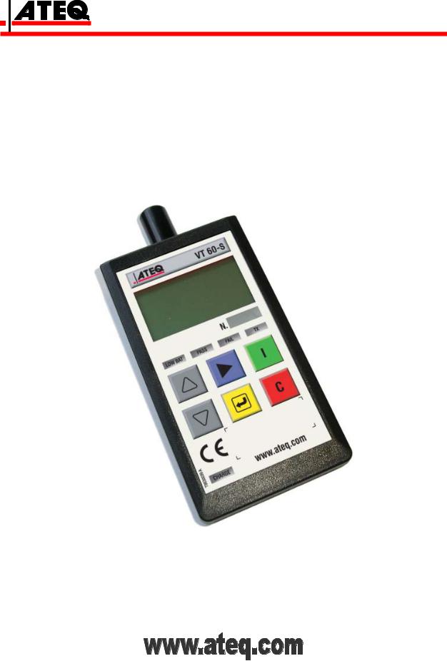
Ateq VT60-S User Manual

USER MANUAL
ATEQ VT60-S
Reference: UM-25810A-U

REVISION OF THE ATEQ VT60-S OWNER'S MANUAL
|
Edition/ |
|
|
Reference |
|
|
Date |
|
|
Chapters updated |
|
|
Revision |
|
|
|
|
(week/year) |
|
|
|
||
|
|
|
|
|
|
|
|
|
|
||
|
|
|
|
|
|
|
|
|
|
|
|
|
First edition |
|
UM-25810A-U |
51/2010 |
|
----- |
|
||||
|
|
|
|
|
|
|
|
|
|
|
|
|
|
|
|
|
|
|
|
|
|
|
|
|
|
|
|
|
|
|
|
|
|
|
|
|
|
|
|
|
|
|
|
|
|
|
|
|
|
|
|
|
|
|
|
|
|
|
|

5110/CE-25810A-U
DECLARATION OF  CONFORMITY 00
We the undersigned, ATEQ, manufacturers of the ATEQ VT60-S REF : 258.10 declare that it complies with the requirements of :
-LOW VOLTAGE Directive 93/68/CEE regarding :
•standard EN 61 010-1 « Safety requirements for electrical equipment for measurement, control and laboratory use »,
-Directive CEM 89/336/CEE partially modified by Directive CEM 92/31/CEE regarding :
•standard EN 50 081-2 « Industrial environment emission generic standard », except in the 95 MHz to 140 MHz range.
•standard EN 50 082-2 « Industrial environment immunity generic standard »,
•standard EN 61 000-4-2 « Test for immunity to electrostatic discharges »,
•standard EN 61 000-4-3 « Test for immunity to electromagnetic fields radiated at radio frequencies »,
This enables ATEQ to guarantee that this instrument may be used in complete safety under the following environmental conditions :
•indoor use,
•altitude up to 3000 metres,
•ambient operating temperature from 5°C to 45 °C,
•70 % maximum relative humidity without condensation,
•degree of pollution 2 as in CEI 664 (only non-conductive pollution. However a temporary conductivity caused by condensation may occasionally be expected ).
Chairman and Managing Director.
Mr. Jacques MOUCHET
Tél. : +33 (0) 1 30 80 10 20 - Fax : +33 (0) 1 30 54 11 00
15, rue des Dames - 78340 LES CLAYES SOUS BOIS – France
www.ateq.com

PREFACE
Dear Customer,
You have just purchased an ATEQ instrument, we thank you for the trust you have placed on our brand. This instrument has been designed to ensure a long and unparalleled life expectancy, and we are convinced that it will give you complete satisfaction during many long years of operation.
In order to maximise the life expectancy and reliability of your ATEQ instrument, we recommend that you install this instrument on a secured workbench and advise you to consult this manual in order to familiarise yourself with the functions and capabilities of the instrument.
Our ATEQ After Sales Service centre can give you recommendations based on your specific operation requirements.
ATEQ
0650/PREFd-U

|
Table of contents |
TABLE OF CONTENTS |
|
User guide |
VT60-S |
1. VT60-S DESCRIPTION........................................................................................................................ |
3 |
1.1. Front face ..................................................................................................................................... |
3 |
1.2. Connectors................................................................................................................................... |
4 |
1.3. Power Supply connector .............................................................................................................. |
4 |
1.4. USB connector ............................................................................................................................. |
4 |
1.5. RJ45 connector ............................................................................................................................ |
4 |
2. LANGUAGES ...................................................................................................................................... |
5 |
3. LIGHT INDICATORS ........................................................................................................................... |
5 |
4. KEYS.................................................................................................................................................... |
6 |
4.1. Power on key................................................................................................................................ |
6 |
4.2. Cancel key.................................................................................................................................... |
7 |
4.3. Cycle key...................................................................................................................................... |
7 |
4.4. Navigations keys .......................................................................................................................... |
8 |
4.5. Validation key............................................................................................................................... |
8 |
4.6. Key Pad summary........................................................................................................................ |
8 |
5. TESTING A TPM SENSOR ................................................................................................................. |
9 |
5.1. Launch a test................................................................................................................................ |
9 |
5.2. Results explanation.................................................................................................................... |
10 |
5.3. No sensor response ................................................................................................................... |
10 |
6. TESTING A REMOTE KEYLESS ENTRY......................................................................................... |
11 |
7. SETTING ADJUSTMENT FOR VT60-S ............................................................................................ |
12 |
8. PARAMETERS SETTING.................................................................................................................. |
13 |
8.1. Pressure unit .............................................................................................................................. |
13 |
8.2. Buzzer ........................................................................................................................................ |
14 |
8.3. Back light.................................................................................................................................... |
15 |
8.4. Auto Off parameter..................................................................................................................... |
16 |
8.5. Zone ........................................................................................................................................... |
17 |
9. FEATURES ........................................................................................................................................ |
18 |
9.1. Radio frequencies ...................................................................................................................... |
18 |
9.2. Type of sensor............................................................................................................................ |
18 |
10. OBD TRANSFER (OPTION)............................................................................................................ |
19 |
10.1. Presentation ............................................................................................................................. |
19 |
10.2. Operation.................................................................................................................................. |
20 |
11. ERROR MESSAGES ....................................................................................................................... |
21 |
12. TROUBLESHOUTINGS AND SOLUTIONS.................................................................................... |
22 |
13. PROGRAM AND DRIVERS INSTALLATION ................................................................................. |
23 |
13.1. Installation under Windows© Vista .......................................................................................... |
23 |
13.2. Installation under Windows© XP.............................................................................................. |
25 |
Appendices |
ATEQ VT60-S |
1. TECHNICAL CHARACTERISTICS ................................................................................................... |
27 |
2. SECURITY, CARE AND RECYCLING.............................................................................................. |
28 |
2.1. Security ...................................................................................................................................... |
28 |
2.2. Care and maintenance............................................................................................................... |
29 |
2.3. Certification information (sar)..................................................................................................... |
29 |
2.4. Safety informations .................................................................................................................... |
30 |
2.5. Recycling.................................................................................................................................... |
31 |
Index |
33 |
UM-25810A-U |
User manual ATEQ VT60-S Page 1/34 |
Table of contents
UM-25810A-U |
User manual ATEQ VT60-S Page 2/34 |

User guide
User guide
VT60-S
See appendices for the security, care, maintenance and recycling information.
1. VT60-S DESCRIPTION
The purpose of the VT60-S is to:
•Retrieve data from the tire pressure sensor.
•Verify the identities of each tire pressure sensor mounted on vehicle wheels.
•Assist a technician to reset TPM system on vehicle.
•Test the RKE signal strength.
•Possibility to transfer data into the vehicle ECU (OBD2 interface option).
The instrument interacts with the tire pressure sensor without contact through wireless communication.
1.1. FRONT FACE |
|
|
|
|
|
|
|
Lights |
|
|
indicators |
Antenna |
|
|
|
|
|
|
|
|
LCD display
Connectors
see below
UM-25810A-U |
User manual ATEQ VT60-S Page 3/34 |

User guide
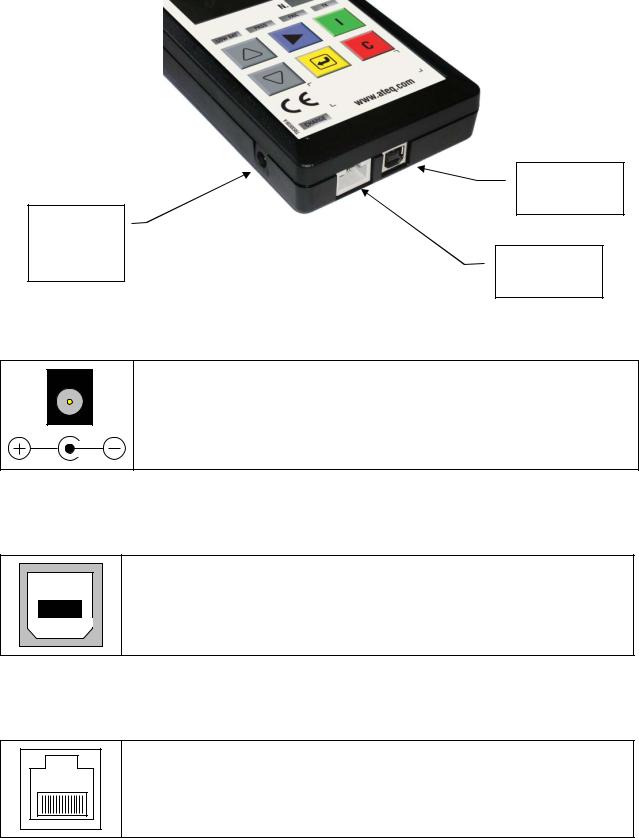
1.2. CONNECTORS
USB connector
24 V DC supply
connector RS232 connector
1.3. POWER SUPPLY CONNECTOR
Power supply connection to the tool for charging the internal battery.
The voltage of the charger is a 24 V DC.
1.4. USB CONNECTOR
The USB connector allows software updates to be installed onto the tool.
1.5. RJ45 CONNECTOR
The RJ45 connector allows to connect the option OBD interface.
UM-25810A-U |
User manual ATEQ VT60-S Page 4/34 |

User guide
2. LANGUAGES
Several languages are available. If the displayed is not suitable, press the  key repeatedly until the menu LANGUAGE appears.
Then by using the |
or |
keys, choose the |
LANGUAGE |
|
|
|
ENGLISH |
suitable menu's language and validate with the |
ESPANOL |
||
key. Languages |
|
|
>FRANCAIS |
|
|
|
|
|
|
|
|
The LANGUAGE menu is also available from the |
MAIN MENU |
||
RKE TEST |
|||
main menu, below the SETTINGS menu. |
SETTINGS |
||
|
|
|
>LANGUAGE |
3. LIGHT INDICATORS
Four lights placed under the LCD display indicate the status of the instrument and the results of the measurement.
|
|
|
|
|
|
Battery level light: When this light is |
Low Bat |
|
Pass |
Fail |
Tx |
Low Bat |
on the battery level is low. |
|
|
|
|
|
Connect the power supply to charge |
|
|
|
|
|
|
|
|
|
|
|
|
|
|
the battery. |
|
|
|
|
|
|
Pass test light: When this light is on |
Low Bat |
|
Pass |
Fail |
Tx |
Pass |
the tool has correctly received the |
|
|
|
|
|
information from the sensor or the |
|
|
|
|
|
|
|
|
|
|
|
|
|
|
remote keyless entry unit. |
|
|
|
|
|
|
Fail test light: When this light is on the |
Low Bat |
|
Pass |
Fail |
Tx |
Fail |
tool has not received the information |
|
|
|
|
|
from the sensor or the remote keyless |
|
|
|
|
|
|
|
|
|
|
|
|
|
|
entry unit. |
|
|
|
|
|
|
Transmission light: When this light is |
|
|
|
|
|
|
flashing the tool is currently transmitting |
Low Bat |
Pass |
Fail |
Tx |
|
Tx |
a signal to activate a sensor. |
|
|
|
|
|
|
|
|
|
|
|
|
|
Note: light may illuminate continuously |
|
|
|
|
|
|
and will not always flash. |
Charge indicator on the bottom of the front face:
|
|
|
Battery charging light: When this red light is on the power supply is |
|
|
|
currently charging the tool. |
|
Charge |
||
|
|
|
When this light switches off the tool battery is filled. |
|
|
|
|
UM-25810A-U |
User manual ATEQ VT60-S Page 5/34 |

User guide
4.KEYS
4.1.POWER ON KEY
KEY |
FUNCTION |
|
|
First function: Power on and Power off: when off press this key to power on the tool. When on press and hold this key more than 3 seconds to power off the tool.
Second function: Indicates the battery level. Press and hold to see the battery status (less than 3 seconds).
4.1.1. First function
At power on, it displays the ATEQ logo.
Then it displays the software revision number. |
ATEQ VT55 |
|
Version CA1.35 |
||
|
||
|
|
And after it displays the test menu with the last tested vehicle, press  one time to return to
the brand selection menu or two times to return to the main menu.
|
FORD |
|
LEFT FRONT |
( ) |
SELECT TIRE |
(C) |
RETURN TO MENU |
(TEST) READ SENSOR
4.1.2. Second function
When the instrument is on, keep pressing this key |
BATTERY |
|
STATUS |
 and the battery level is displayed (less than 3 seconds).
When the “LOW BATT” light flashes the |
|
|
|
|
instrument will turn off. |
Low Bat |
Pass |
Fail |
Tx |
Connect the power supply to charge the battery.
UM-25810A-U |
User manual ATEQ VT60-S Page 6/34 |
 Loading...