

Page 1
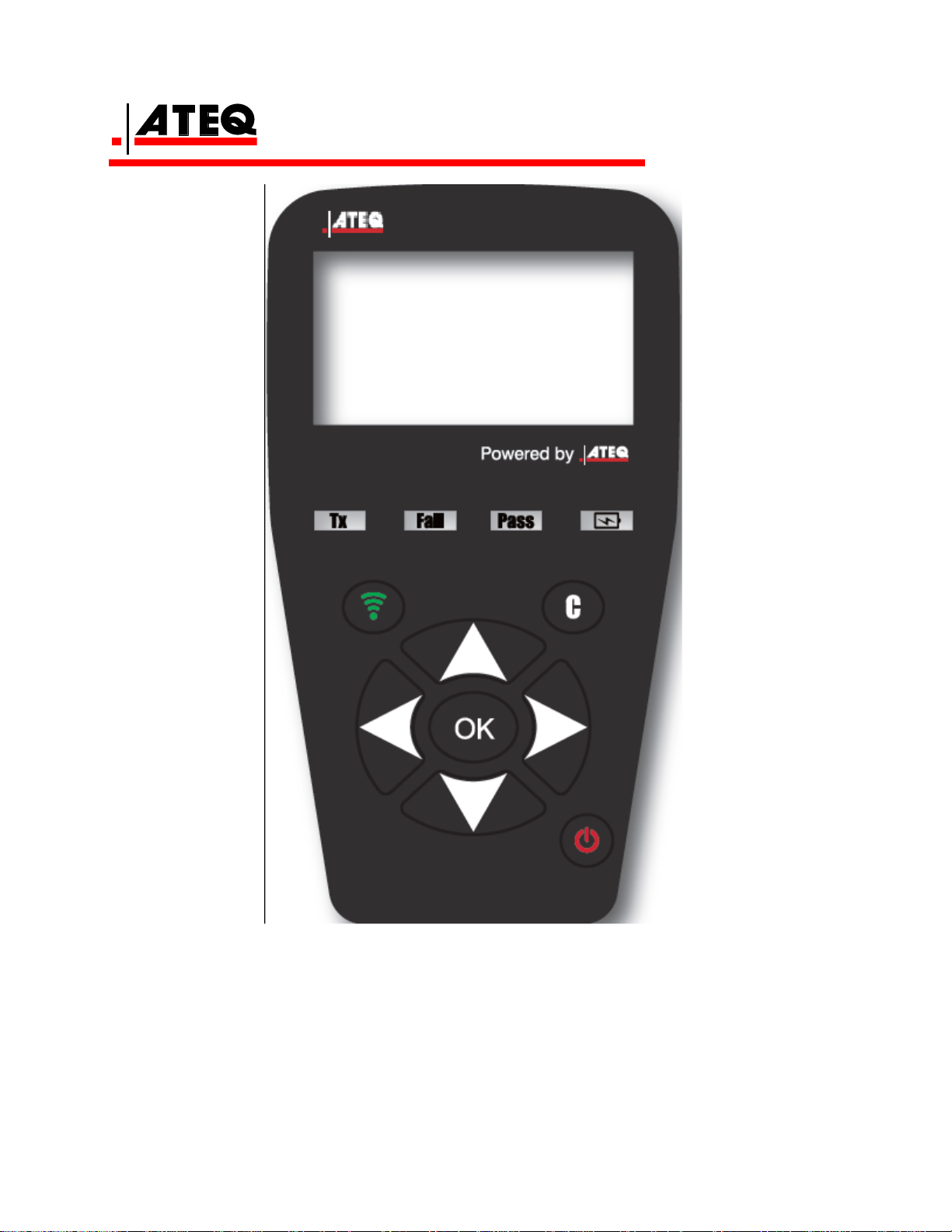
Reference Guide
Section A – General Description
Section B – How to use the VT36
VT36 GB VHA1-00-0ϯ
Page 2
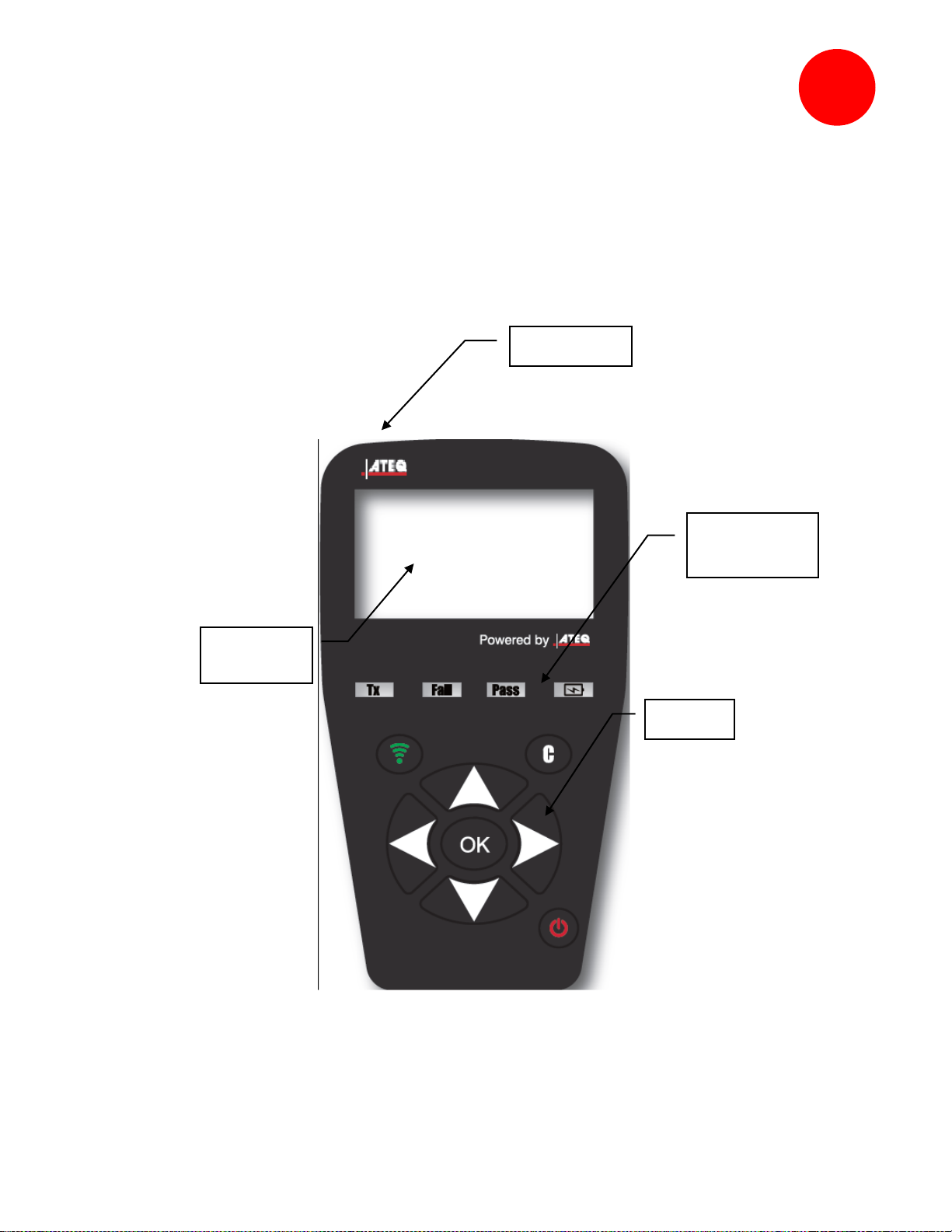
General Description of the ATEQ VT36
Lights
indicators
Keypad
LF Antenna
LCD
display
A
The principle of this instrument is to awaken and then retrieve data from smart valves mounted
on vehicle wheels, in order to check their identifiers. The instrument interacts with the smart
valves to assist technicians service Tire Pressure Monitor Systems (TPMS). VT36 is capable to
trigger all know sensors.
Front face
VT36 GB VHA1-00-0ϯ
Page 3
SET
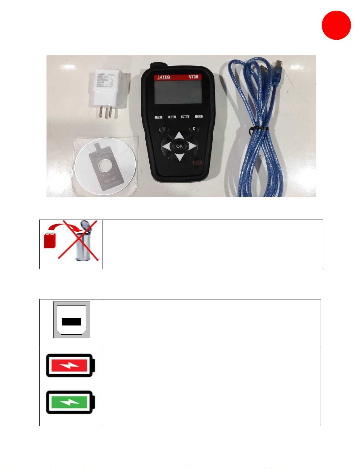
VT36 Operates with rechargeable battery Type Li-On.
The USB connection allows software updates to be installed onto the
tool using the WEB VT program.
TPM sensor results can also be printed using this program.
The USB connection allows to charge the internal battery.
The symbol is red during the charge.
The symbol becomes green when the charge is complete.
It can be done from a PC (14 hours) or with the wall charger (5 hours).
A
Battery
USB connector / Charging the battery
VT36 GB VHA1-00-0ϯ
Page 4
SECTION B – HOW TO USE THE VT36
B
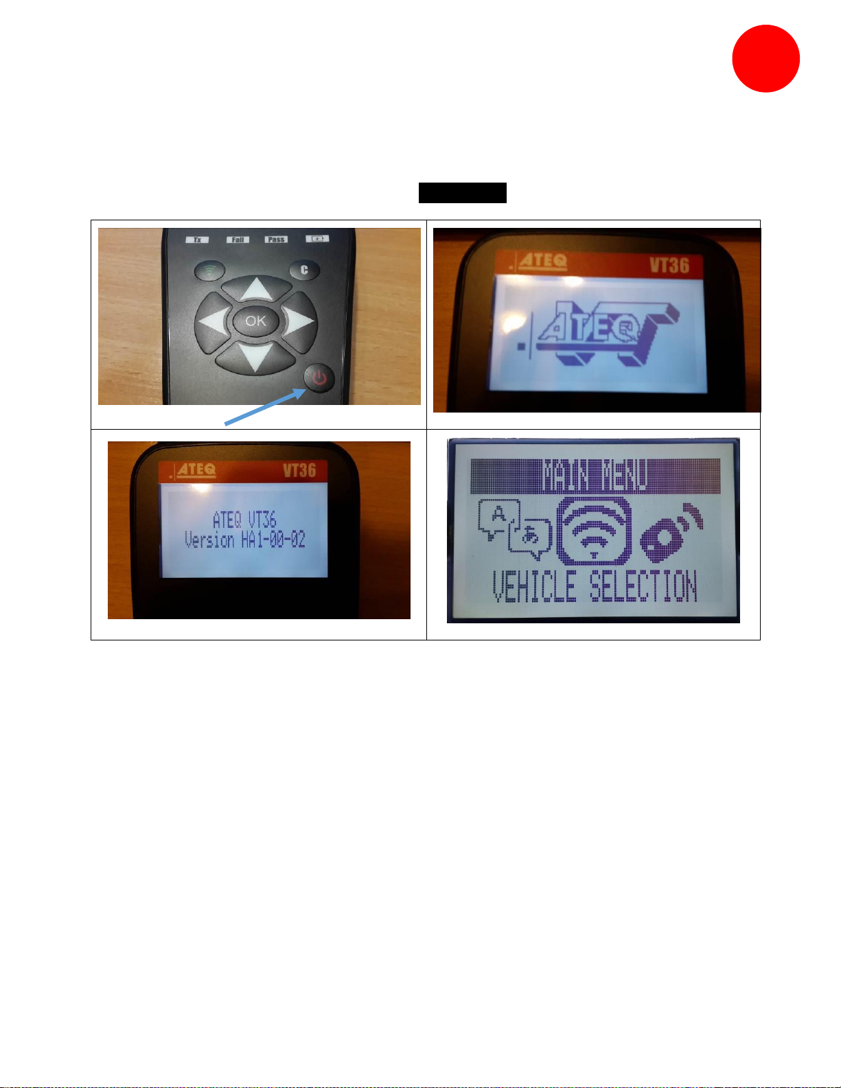
B.0 SWITCH ON THE VT36
Please, wait until the welcome screen shows “ MAIN MENU “.
VT36 GB VHA1-00-0ϯ
Page 5
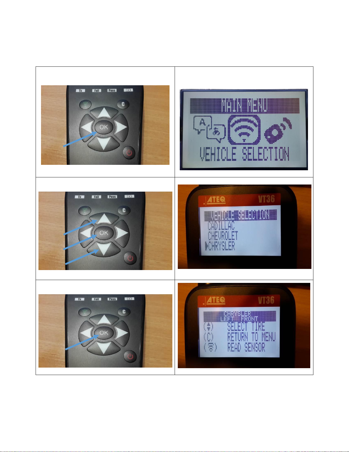
B.1 TESTING A TPM SENSOR
Confirm the choice : VEHICLE SELECTION
Select the brand then confirm
Select 4 or 5 wheels then confirm
VT36 GB VHA1-00-0ϯ
Page 6
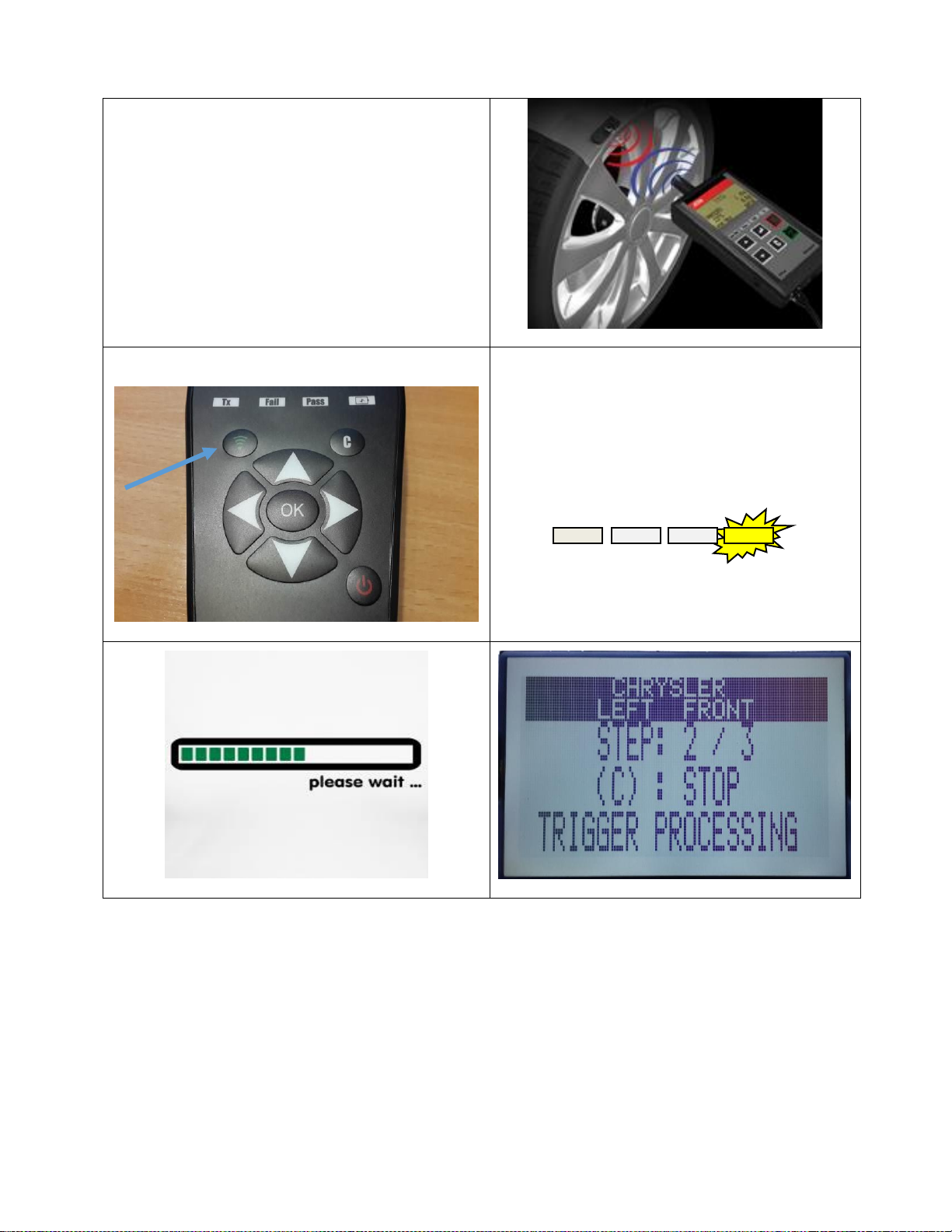
Hold the VT36 directly on the rubber
tire, over the valve stem.
Some sensors are banded to the wheel
and can be located 180⁰ opposite the
valve stem. (Refer to owner’s manual)
Start the test cycle
During the trigger processing,
the yellow light is blinking
Low Bat
Pass
Fail
Tx
VT36 GB VHA1-00-0ϯ
Page 7
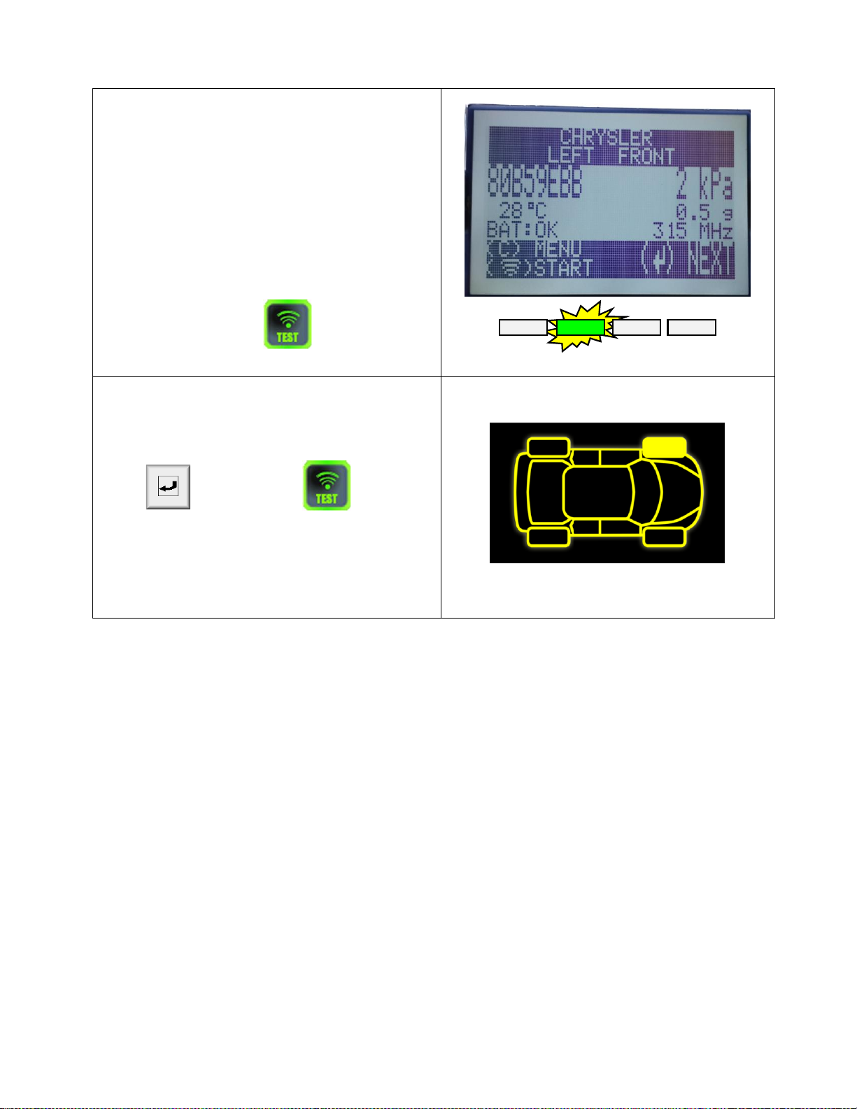
The tool will vibrate/beep after receiving
the sensor information. The tool will
display the sensor ID, pressure, and
sensor state of the valve that is triggered.
If the tool does not receive the correct
information, the fail LED will illuminate
and you can restart the trigger sequence
by pressing the key again.
Low Bat
Pass
Fail
Tx
Follow the same procedure for the rest of
the three or four wheels by pressing the
key and then key.
(Refer to vehicle owner’s manual or other
reference guides for TPM reset
procedure.)
VT36 GB VHA1-00-0ϯ
Page 8
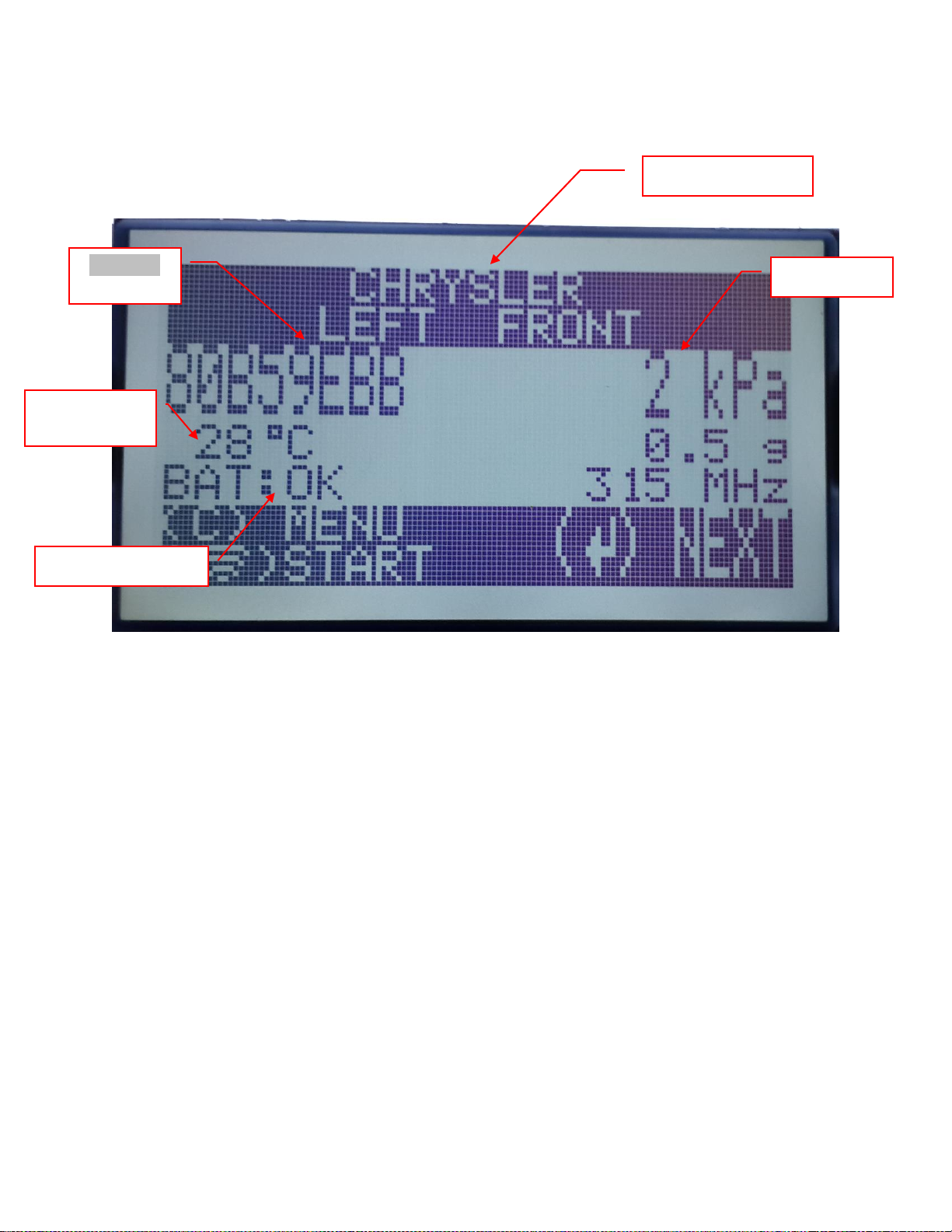
The picture below is an example of a valve data communication result:
Vehicle make
Pressure
Battery Status
Valve ID
Temperature
**Note: The VT36 will identify the sensor information that is transmitted. Not
all sensors transmit every piece of information shown. ***
VT36 GB VHA1-00-Ϭϯ
Page 9
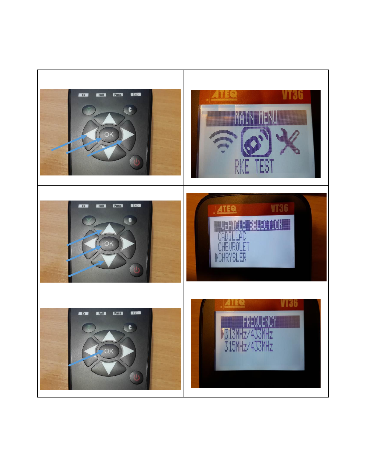
B.2 TESTING A KEY (RKE TEST)
Confirm the choice : KEY FOB
Select the brand then confirm
Select radio frequencies then confirm
VT36 GB VHA1-00-0ϯ
Page 10
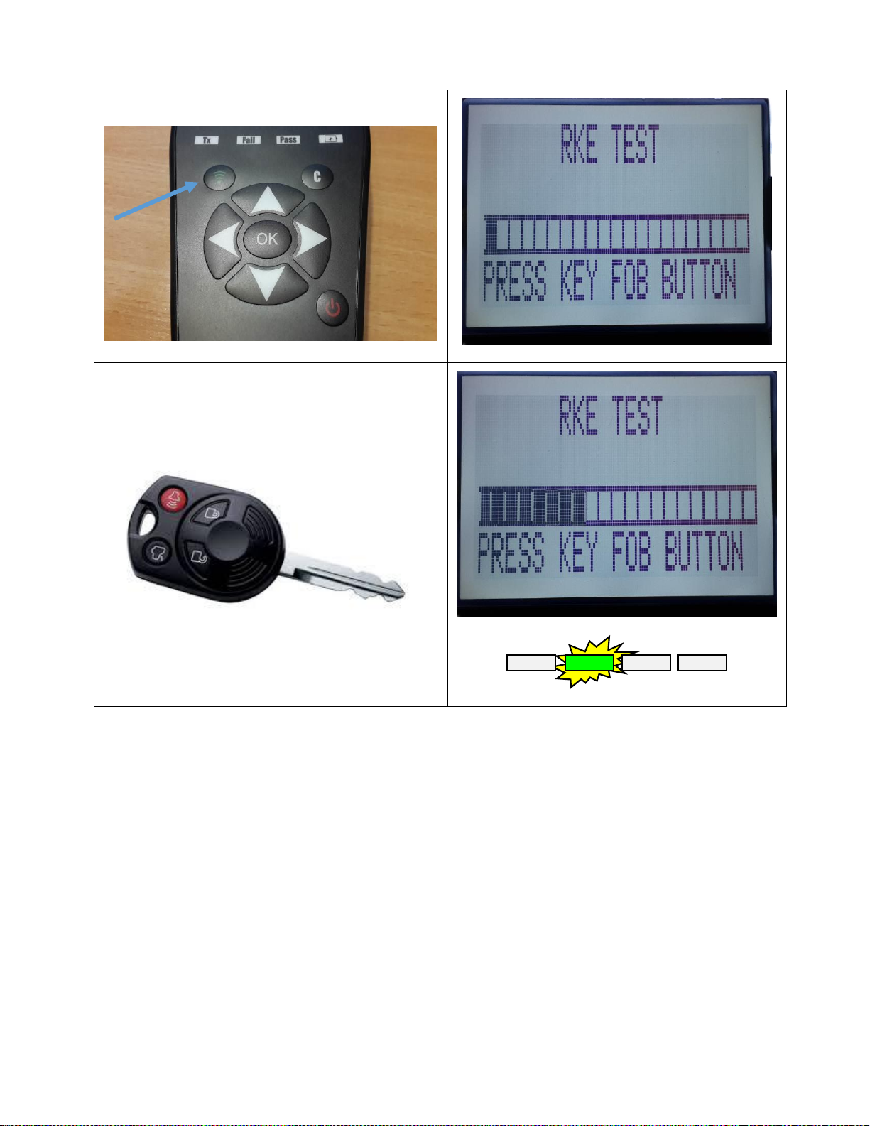
Start the test cycle
Check the key
Low Bat
Pass
Fail
Tx
VT36 GB VHA1-00-0ϯ
Page 11
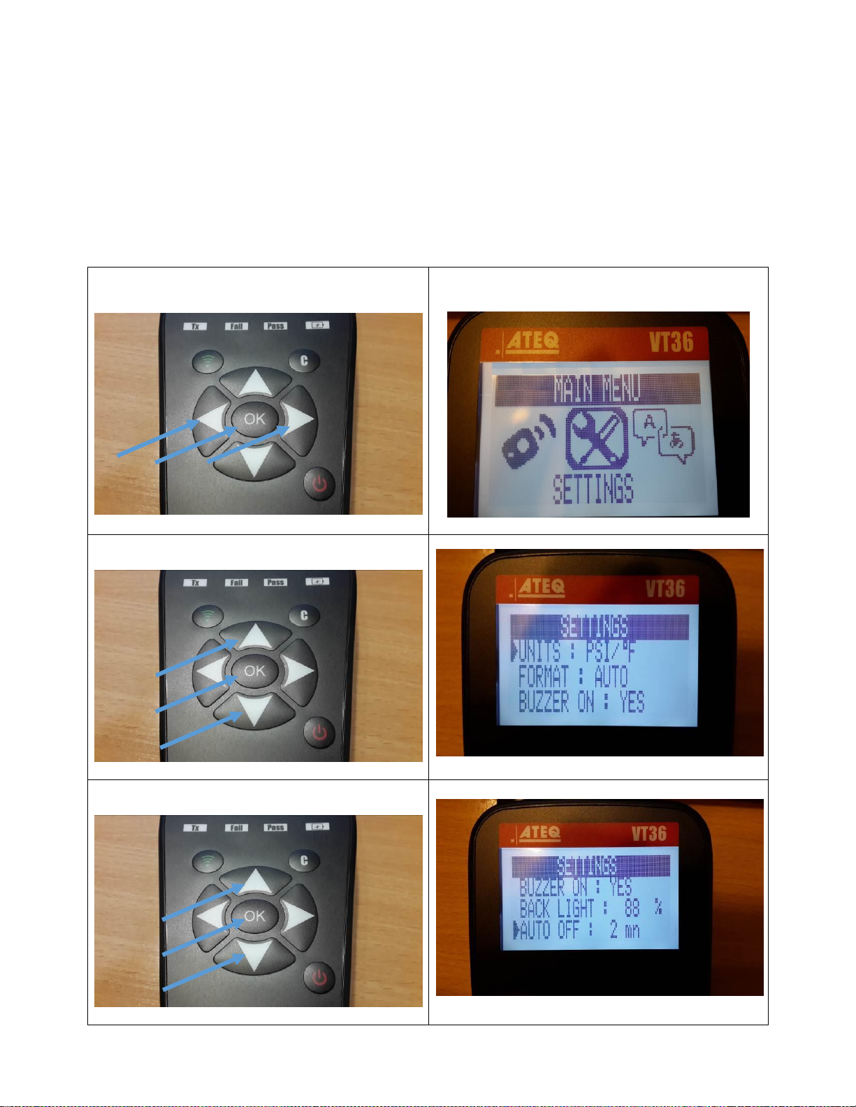
B.3 SETTING
Confirm the choice : SETTING
Select the item then confirm (OK)
Select the item then confirm (OK)
SETTING allows to change :
The pressure and temperature unit
The format (AUTO is recommended)
The buzzer ON or OFF
The contrast
AUTO OFF for saving battery. (1 to 2 mn is recommended)
VT36 GB VHA1-00-0ϯ
Page 12
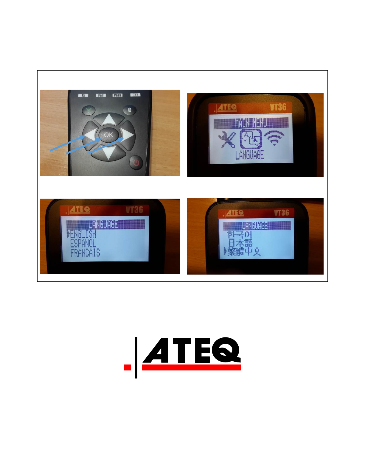
B.4 LANGUAGE
Confirm the choice : LANGUAGE
SELECT the language then confirm (OK).
SELECT the language then confirm (OK).
LANGUAGE allows to select different language :
Web Site TPMS : www.tpms-tool.com
VT36 GB VHA1-00-0ϯ
Page 13

Federal Communication Commission Interference Statement
This equipment has been tested and found to comply with the limits for a Class B
digital device, pursuant to Part 15 of the FCC Rules. These limits are designed to provide
reasonable protection against harmful interference in a residential installation. This
equipment generates, uses and can radiate radio frequency energy and, if not installed
and used in accordance with the instructions, may cause harmful interference to radio
communications. However, there is no guarantee that interference will not occur in a
particular installation. If this equipment does cause harmful interference to radio or
television reception, which can be determined by turning the equipment off and on, the
user is encouraged to try to correct the interference by one of the following measures:
- Reorient or relocate the receiving antenna.
- Increase the separation between the equipment and receiver.
- Connect the equipment into an outlet on a circuit different from that
to which the receiver is connected.
- Consult the dealer or an experienced radio/TV technician for help.
FCC Caution: Any changes or modifications not expressly approved by the party
responsible for compliance could void the user's authority to operate this equipment.
This device complies with Part 15 of the FCC Rules. Operation is subject to the
following two conditions: (1) This device may not cause harmful interference, and (2) this
device must accept any interference received, including interference that may cause
undesired operation.
VT36 GB VHA1-00-0
ϯ
 Loading...