

Page 1
USER MANUAL
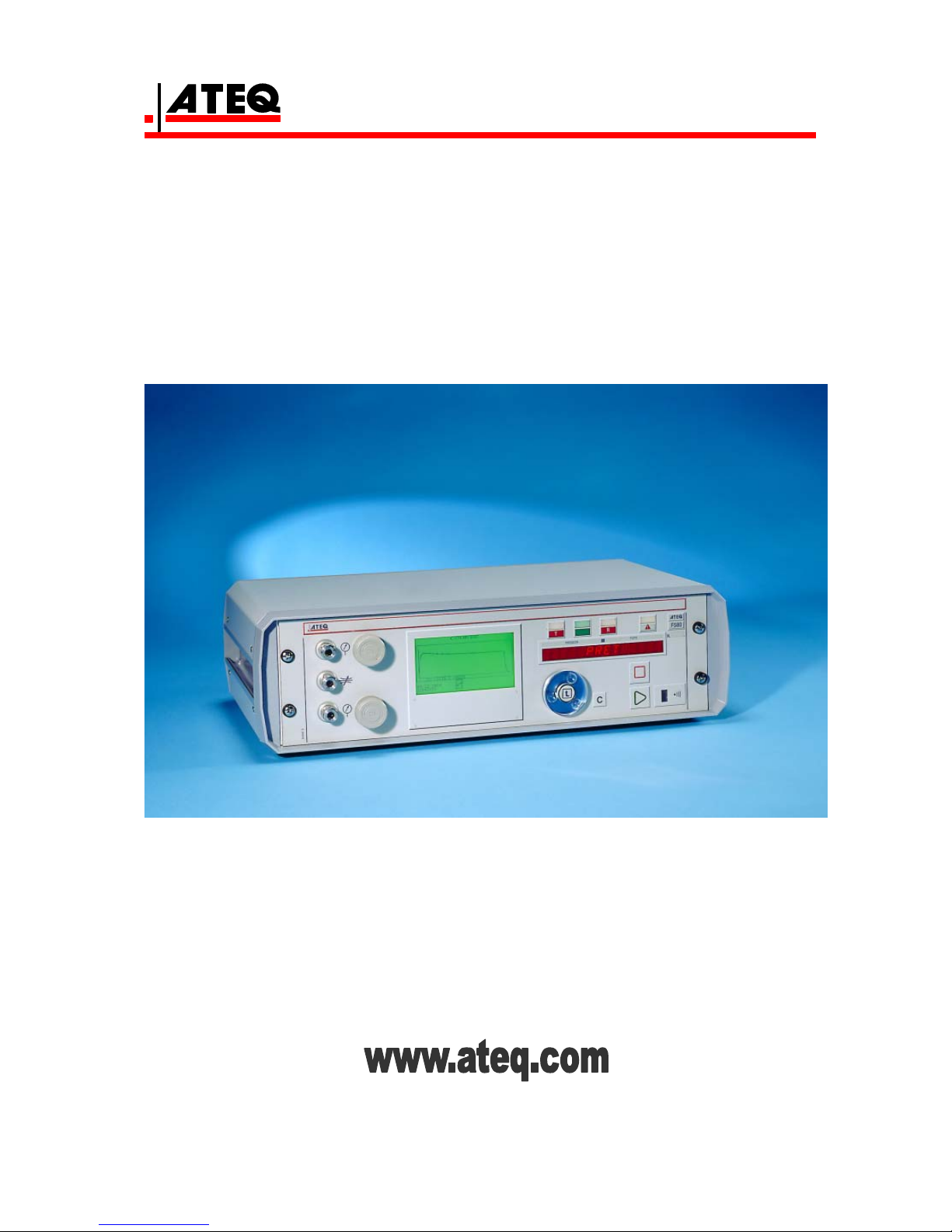
ATEQ F580
Version 1.03
Factory after 2005 august 01
+
ATEQ F20A, F20D, 5xx Series
pneumatic heads
Reference: UM-18400E-U
Page 2

Page 3
REVISION OF THE F580 USER MANUAL
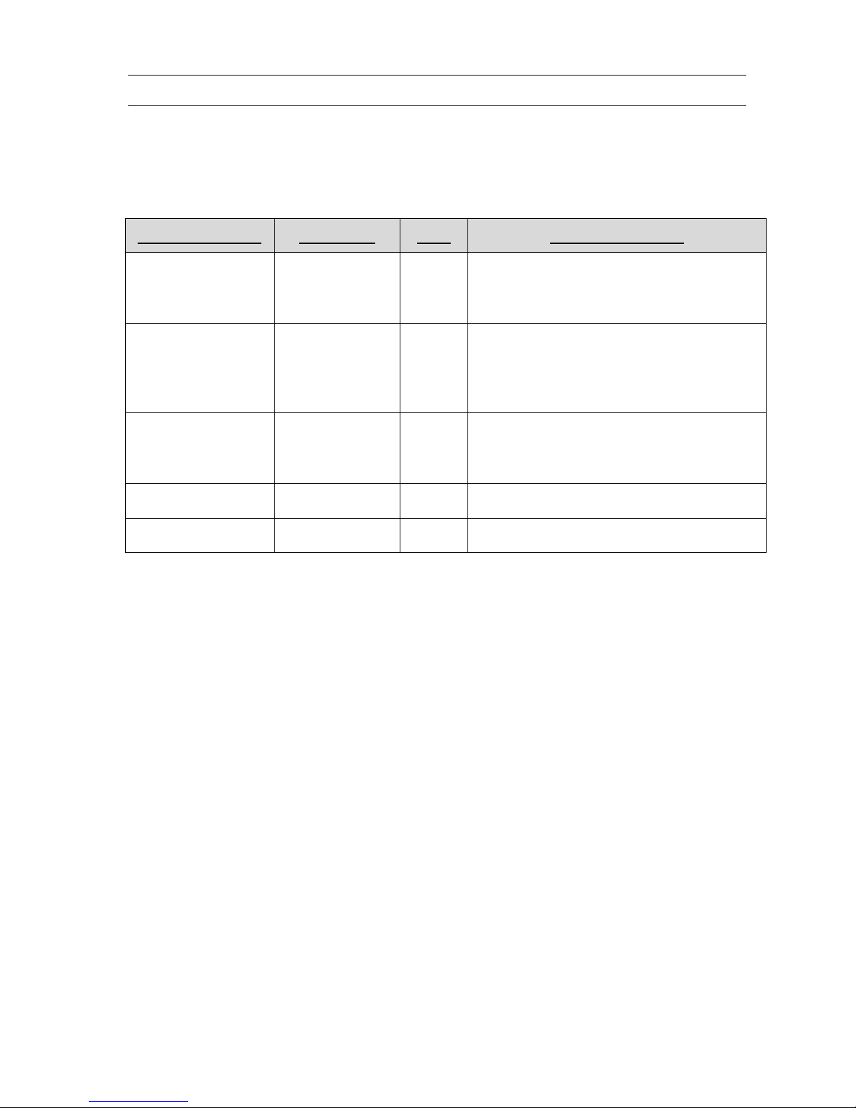
Edition/Revision Reference Date Chapters updated
First edition UM-18400C-U 25/03
Up dating of the software version 1.01 >
1.03, edition of the F580 only. I/O
configuration mode.
Second edition UM-18400D-U 12/2005
Evolution of the head version to 1.16, up
dating the network scheme on chapter 1
and the pressure specifications in
preamble.
Third edition UM-18400E-U 47/2007
Up dating the network (factory after 2005
august 1st). Remove the 65 to 128
programs selection.
Page 4

Page 5

Recommendations for leak testing
instruments
0039/Ret-U
Precautions for the test environment
• Keep the test area as clean as possible.
Precautions for the operators
• ATEQ recommends that the operators using the instruments should have a
suitable qualification and training with respect to the work bench requirements.
General precautions
• Read the user manual before using the instrument,
• all electrical connections to the instrument must be equipped with a safety
system (fuse, circuit breaker…) appropriate to its needs and complying with the
standards,
• to avoid electromagnetic interference, the cable connections to the instrument
should be less than two meters in length,
• it is essential that the electrical main is earthed,
• disconnect the electrical connections to the equipment before maintenance,
• cut the air supply for any kinds of operation on the pneumatic assembly,
• do not open the instrument when it is powered up,
• avoid water spillage near of the instrument,
• ATEQ is at your disposal for any further information concerning the use of the
instrument under maximum safety conditions.
We would like to bring to your attention that ATEQ will not be held responsible
for any accident connected to the improper use of the instrument, to the work
bench or to the lack of compliance with safety rules.
ATEQ Company is free from any responsibility for any adjustment of its
instrument which would not have been done by its own technicians.
Page 6

Page 7
SAV-Ub/0243
ATEQ, THE ASSURANCE OF A COMPETENT AFTER SALES
SERVICE
THE ATEQ AFTER SALES SERVICE IS :
• a team of qualified technicians,
• a permanent telephone assistance,
• agencies close to you for faster reaction,
• a stock of spare parts available immediately,
• a car fleet for rapid intervention,
• a commitment to quality ...
THE OVERHAUL
ATEQ carries out the overhaul of your instruments at interesting prices.
The overhaul corresponds to the maintenance of the instrument (checking, cleaning, replacing of used
parts) as part of preventive maintenance.
Preventive maintenance is the best way to guarantee reliability and efficiency. It allows the
maintenance of a group of instruments in good operational order and prevent eventual break-downs.
MAINTENANCE KITS
The ATEQ After Sales Service proposes, two kits destined for the preventive maintenance of the
pneumatic circuits of instruments.
CALIBRATION
This may be carried out on site or in our offices.
ATEQ is attached to the COFRAC and delivers a certificate following a calibration.
TRAINING COURSES
In the framework of partnership with our customers, ATEQ offers two types of training in order to
optimise the usage and knowledge of our instruments. They are aimed at different levels of technician:
• method / control training,
• maintenance / upkeep training.
A TARGETED TECHNICAL DOCUMENTATION
A number of technical documents are at your disposal to allow you to intervene rapidly in the event
minor breakdowns:
• problem sheets describing and offering solutions to the main pneumatic and electronic
problems,
• several maintenance manuals.
A QUALITY GUARANTEE
The instruments are guaranteed for parts and labour in our offices:
• 2 years for leak detection equipment,
• 1 year for electrical tests to norms instruments,
• 1 year for the accessories.
Our After Sales Service is capable of rapidly answering all your needs and queries.
ATEQ recommends
to made realise by its departments
a revision and a calibration of the instruments
every year
Page 8

Page 9

0650/PREFd-U
PREFACE
Dear Customer,
You have just purchased an ATEQ instrument, we thank you for the trust you have
placed on our brand. This instrument has been designed to ensure a long and
unparalleled life expectancy, and we are convinced that it will give you complete
satisfaction during many long years of operation.
In order to maximise the life expectancy and reliability of your ATEQ instrument, we
recommend that you install this instrument on a secured workbench and advise you to
consult this manual in order to familiarise yourself with the functions and capabilities of
the instrument.
Our ATEQ After Sales Service centre can give you recommendations based on your
specific operation requirements.
ATEQ
Page 10

Page 11

Table of contents
UM-18400E-U ATEQ F580 User manual Page 1/168
TABLE OF CONTENTS
PREAMBLE 5
1. DEFINITION OF THE ATEQ F580 ......................................................................................................5
2. MEASUREMENT CHARACTERISTICS..............................................................................................6
2.1. Pressure drop measurement........................................................................................................6
2.2. Test pressure measurement ........................................................................................................6
2.3. Pressure regulation ......................................................................................................................6
3. THE MAIN TYPES OF MEASUREMENTS .........................................................................................7
3.1. Direct/Pressure drop measurement .............................................................................................7
3.2. Indirect/ Pressure rise measurement ...........................................................................................7
3.3. Sealed component measurement ................................................................................................7
4. THE THREE TYPES OF TEST ............................................................................................................8
4.1. Test with reference.......................................................................................................................8
4.2. Test without reference..................................................................................................................8
4.3. Test with central naught ...............................................................................................................8
5. DIRECT MEASUREMENT, PRESSURISATION.................................................................................9
6. SYMBOLS PRESENTATION ............................................................................................................10
Chapter 1 INSTALLATION OF THE INSTRUMENT
1. APPEARANCE OF THE ATEQ F580................................................................................................11
2. BASICS RECOMMENDATIONS .......................................................................................................12
3. INSTALLATION AND CABLING.......................................................................................................13
3.1. Control unit physically positionned between the heads .............................................................13
4. INSTALLATION OF THE ATEQ F580 ..............................................................................................14
4.1. Start / Stop switch ......................................................................................................................14
4.2. Layout of connectors on case ....................................................................................................14
4.3. Details of connectors..................................................................................................................14
Chapter 2 USER INTERFACES
1. APPEARANCE OF FRONT PANEL OF ATEQ F580 .......................................................................29
2. APPEARANCE OF KEYBOARD ......................................................................................................30
2.1. Validation and escape keys .......................................................................................................30
2.2. Cycle keys ..................................................................................................................................30
3. LOCK SWITCH ..................................................................................................................................31
4. DISPLAYS AND LIGHTS ..................................................................................................................32
4.1. 16 line lcd display.......................................................................................................................32
4.2. 14 character led display .............................................................................................................32
4.3. Meanings of indicator lights........................................................................................................32
5. INFRARED INTERFACE ...................................................................................................................33
6. RAPID CONNECTORS......................................................................................................................33
Chapter 3 START-UP AND SETTINGS
1. POWERING-UP THE INSTRUMENT ................................................................................................35
2. START-UP OF THE NETWORK .......................................................................................................36
3. ALLOCATION OF THE OUTPUTS ...................................................................................................38
3.1. Outputs allocation mode ............................................................................................................38
3.2. Allocation of the modules ...........................................................................................................39
4. MANAGEMENT OF THE MEASUREMENT UNITS..........................................................................40
4.1. Measurement unit (head) configuration .....................................................................................40
4.2. Creation of a test program .........................................................................................................42
4.3. Test type selection .....................................................................................................................44
4.4. Parameter settings .....................................................................................................................46
5. DUPLICATION OF A TEST PROGRAM ...........................................................................................51
6. DELETING A TEST PROGRAM........................................................................................................52
7. LAUNCHING A CYCLE .....................................................................................................................53
Page 12
Table of contents
UM-18400E-U ATEQ F580 User manual Page 2/168
7.1. Start key .....................................................................................................................................53
7.2. Display of the measurements.....................................................................................................53
7.3. Choice of the measurement unit program..................................................................................54
8. LAUNCH OF A SPECIAL CYCLE.....................................................................................................55
9. ADJUSTMENT OF THE TEST PRESSURE .....................................................................................57
9.1. Manual adjustment with mechanical regulator...........................................................................57
9.2. Instruction adjustment with mechanical regulator......................................................................58
9.3. Setting a filling instruction with an electronic regulator ..............................................................60
10. STOPPING A CYCLE ......................................................................................................................60
Chapter 4 FUNCTIONS OF THE INSTRUMENT
1. CENTRAL ..........................................................................................................................................61
1.1. menu structure ...........................................................................................................................61
1.2. RUN MENU ......................................................................................................................64
1.3. PARAMETERS MENU ....................................................................................................65
1.4. display MENU ..................................................................................................................66
1.5. CONFIGURATION MENU ...............................................................................................70
1.6. SERVICE MENU ..............................................................................................................74
1.7. RESULTS MENU .............................................................................................................81
2. F5 HEAD ............................................................................................................................................82
2.1. menu STRUCTURE ...................................................................................................................82
2.2. Configuration menu....................................................................................................................92
3. SPECIAL CYCLES MENU...............................................................................................................125
3.1. Special cycles available ...........................................................................................................125
3.2. Available service special cycles ...............................................................................................127
3.3. Start special cycles ..................................................................................................................128
3.4. Starting the Service special cycles...........................................................................................139
Chapter 5 ACCESSORIES
1. ACCESSORIES SUPPLIED WITH THE INSTRUMENT.................................................................143
1.1. Power supply cable ..................................................................................................................143
2. OPTIONAL ACCESSORIES............................................................................................................144
2.1. Calibrated leak .........................................................................................................................144
2.2. Needle valve and leak/flow calibrator (CDF)............................................................................145
2.3. Optional remote input / output module.....................................................................................146
2.4. PS5 junction box module .........................................................................................................149
2.5. 24 V DC power supplies...........................................................................................................150
2.6. Power consumption table.........................................................................................................151
2.7. Installation synopsis .................................................................................................................152
2.8. F5 to F3 interface relay board ..................................................................................................153
2.9. Automatic connectors with expanding joints ............................................................................154
2.10. Filtration kit .............................................................................................................................154
Chapter 6 ERROR MESSAGES
1. ERROR FOR THE CENTRAL .........................................................................................................155
2. ERROR FOR ONE HEAD................................................................................................................156
Page 13

Table of contents
UM-18400E-U ATEQ F580 User manual Page 3/168
Appendices ATEQ F580
1. TECHNICAL CHARACTERISTICS .................................................................................................161
2. DEFINITION DRAWING OF MECHANICAL PARTS......................................................................162
2.1. F580 control unit ......................................................................................................................162
2.2. Pneumatic heads .....................................................................................................................163
3. CONVERSION TABLE ....................................................................................................................164
4. PARAMETERS STORED ................................................................................................................165
5. VALVES CODES USED IN YOUR APPLICATION ........................................................................166
Index 167
Page 14

Table of contents
UM-18400E-U ATEQ F580 User manual Page 4/168
Page 15
Preamble
UM-18400E-U ATEQ F580 User manual Page 5/168
PREAMBLE
1. DEFINITION OF THE ATEQ F580
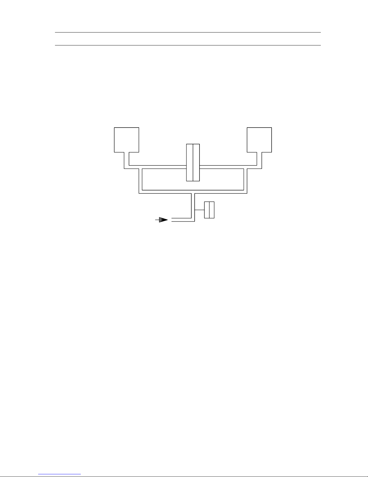
The ATEQ F580 is a compact air/air leak detector used to control the air-tightness of
parts on production lines. It is especially adapted to manual and semi-automatic
workbenches. The method used is based on the measurement of a small variation or
drop in differential pressure between both the test and reference parts, when both are
filled with an identical pressure.
PIEZO SENSOR
TEST AIR
PRESSURE
REFERENCE PART
DIFFERENTIAL SENSOR
TEST PART
Page 16
Preamble
UM-18400E-U ATEQ F580 User manual Page 6/168
2. MEASUREMENT CHARACTERISTICS
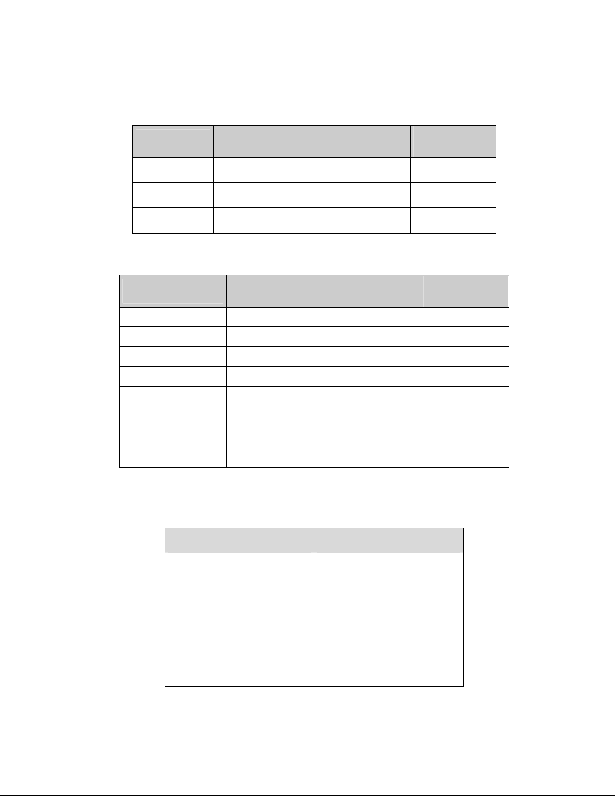
2.1. PRESSURE DROP MEASUREMENT
RANGE
ACCURACY
Maximum
RESOLUTION
0 – 50 Pa +/- (2,5% of the pressure + 1 Pa 0,01 Pa
0 – 500 Pa +/- (2,5% of the pressure + 1 Pa 0,1 Pa
0 – 5000 Pa +/- (2,5% of the pressure + 10 Pa 1 Pa
2.2. TEST PRESSURE MEASUREMENT
RANGE
ACCURACY
Maximum
RESOLUTION
PE = 75 mbar* +/- (1,5% of the pressure+ 0,2 hPa) 0,1 % PE
PE < 0,3 bar +/- (1,5% of the pressure + 1 hPa) 0,1 % PE
0,3 ≤ PE ≤ 1 bar
+/- (1,5% of the pressure + 3 hPa) 0,1 % PE
1 < PE ≤ 5 bar
+/- (1,5% of the pressure + 7.5 hPa) 0,1 % PE
5 < PE ≤ 10 bar
+/- (1,5% of the pressure + 15 hPa) 0,1 % PE
10 < PE ≤ 20 bar
+/- (1,5% of the pressure + 30 hPa) 0,1 % PE
20 < PE ≤ 50 bar
+/- (1,5% of the pressure + 75 hPa) 0,1 % PE
PE = 100 bar
+/- (1,5% of the pressure + 150 hPa) 0,1 % PE
* Specific (relative).
2.3. P
RESSURE REGULATION
Mechanical regulator Electronic regulator
- 80 kPa to - 2 kPa
5 kPa to 50 kPa
20 kPa to 400 kPa
50 kPa to 800 kPa
50 kPa to 1600 kPa
- 80 kPa to - 2 kPa
1 kPa to 10 kPa
5 kPa to 50 kPa
20 kPa to200 kPa
50 kPa to 500 kPa
100 kPa to 1000 kPa
100 kPa to 1600 kPa
100 kPa to 2000 kPa
For other specific pressures please contact ATEQ.
Page 17
Preamble
UM-18400E-U ATEQ F580 User manual Page 7/168
3. THE MAIN TYPES OF MEASUREMENTS
There exist three measurement methods:
Direct measurement, indirect measurement and sealed component measurement.
These three methods apply to both measurements taken under pressurised or vacuum
conditions.
The configuration is established in function of the application and must be carried out
prior to the use of the instrument.
3.1. DIRECT/PRESSURE DROP MEASUREMENT
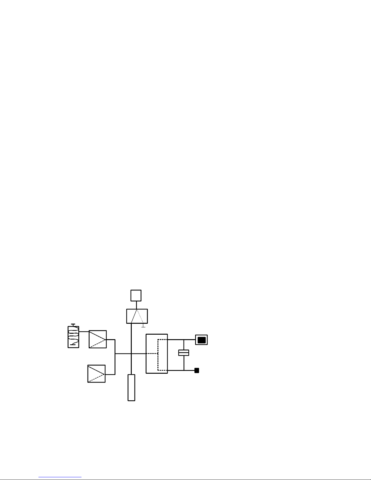
After filling the test and reference parts with the required level of pressure, the
instrument measures the differential pressure between the two volumes, which, are
separated by the equalisation valve.
At the end of a cycle, the ATEQ empties the components via the dump valve.
3.2. INDIRECT/ PRESSURE RISE MEASUREMENT
The test part is placed in a sealed bell to which the instrument is pneumatically connected to
the bell. The part is externally pressurised (with up to 20 MPa, 200 bar), and the bell is lightly
pressurised. In the event of a part leakage, the pressure in the bell will rise. This method
allows the testing of certain parts at high pressure levels whilst avoiding the associated
constraints. The instrument only controls and measures the pressure in the bell. In the event
of a large leak, an electronic monitoring of the pressure in the bell will switch the instrument to
safety.
3.3. S
EALED COMPONENT MEASUREMENT
INTERNAL VOLUME
FILL
VALVE
REGULATOR
DUMP VALVE
ELECTRONIC
PRESSURE SWITCH
REFERENCE PART
PLUG
BELL
PART
SENSOR
This test is for hermetically
sealed parts, which may not be
filled. They are placed under a
bell which is pressurised.
The first and the third measurements may be carried out in comparison with a
reference, without reference or in central naught.
Page 18
Preamble
UM-18400E-U ATEQ F580 User manual Page 8/168
4. THE THREE TYPES OF TEST
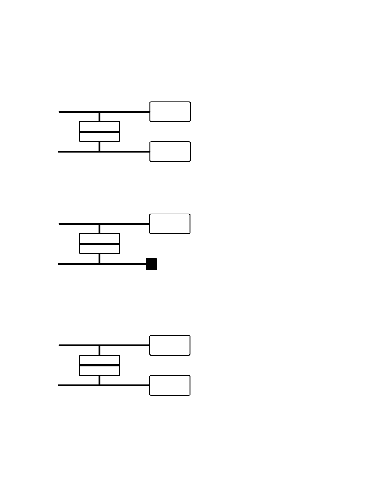
4.1. TEST WITH REFERENCE
TEST PART
SENSOR
REFERENCE PART
Measurement of a pressure variation
between a test part and a reference part.
The ideal measurement conditions are:
identical reference part and identical
ATEQ connections to both parts (identical
lengths, diameters, and natures of the
pipes). The measurement taken with a
reference part will shorten the time taken
for the pressure equalisation occur. It is
valid for parts which cannot be deformed
and which mimic thermal and mechanical
effects.
4.2. TEST WITHOUT REFERENCE
TEST PART
SENSOR
PLUG
Measurement of a variation in pressure
between a test part and a plug on the
reference side. A test without reference is
not recommended, except if parts with
very small volumes are being tested. It is
preferable to always have a certain
volume on the reference side.
4.3. TEST WITH CENTRAL NAUGHT
TEST PART
SENSOR
TEST PART
It is possible to test two parts at the same
time. One part is connected to the test
side and the other to the reference side.
The differential sensor measures the drop
in pressure of one part in respect of the
other. This method may be used when
the number of bad parts is very low
(generally inferior to 1%). The probability
of having two bad parts at the same time
is very low. This method is also used for
distortable parts and parts with a constant
temperature which is different to the
ambient temperature. The central naught
test offers a considerable time advantage
(two parts tested simultaneously).
Page 19
Preamble
UM-18400E-U ATEQ F580 User manual Page 9/168
5. DIRECT MEASUREMENT, PRESSURISATION
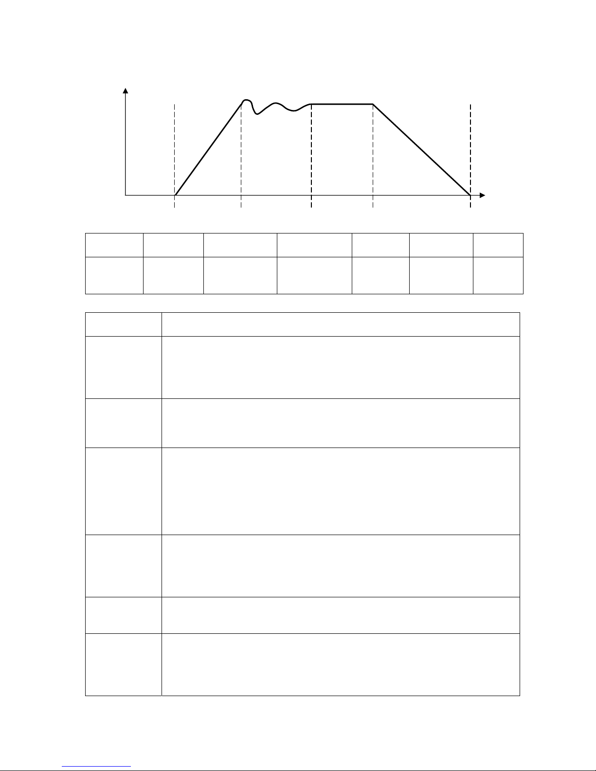
FILL STABILISATION TEST DUMP WAIT
The measurement cycle consists of 5 phases :
1 2 3 4 5
Start
Wait Fill Stabilisation Test Dump
End of
cycle
Start
Cycle launch.
The wait
time
Time during which the plugging of the test parts is carried out before
the part is filled. The instrument may be equipped with the automatic
connector option. This valve, controlled for the duration of the cycle
allows the control of the automated expandable joint connectors.
The fill time
Pressurisation of the test and reference parts. At the end of the fill time,
the ATEQ instrument controls the test pressure, if this is not correct, it
will signal a test pressure error.
The
Stabilisation
time
Test and reference parts are completely cut off from the air supply, but
are pressurised to the test pressure level. Pressure and temperature
will then stabilise between the two parts which communicate and act
similarly. If the test pressure is incorrect (an important leakage on one
of the volumes) the test pressure will drop rapidly, the instrument will
not move on to the test mode and will indicate a fault.
The test time
Test and reference parts are isolated from each other and the pressure
sensor measures the difference in pressure between them. The signal
is electronically assessed and displayed, the part is then diagnosed as
good or bad.
The dump
time
Return of the parts to the atmospheric conditions.
Cycle end
Once the dump has been carried out, the instrument emits a cycle end
signal and the automatic connector valve (option) is deactivated. This
valve can control one or more expandable connectors from the
beginning to the end of the cycle.
Page 20
Preamble
UM-18400E-U ATEQ F580 User manual Page 10/168
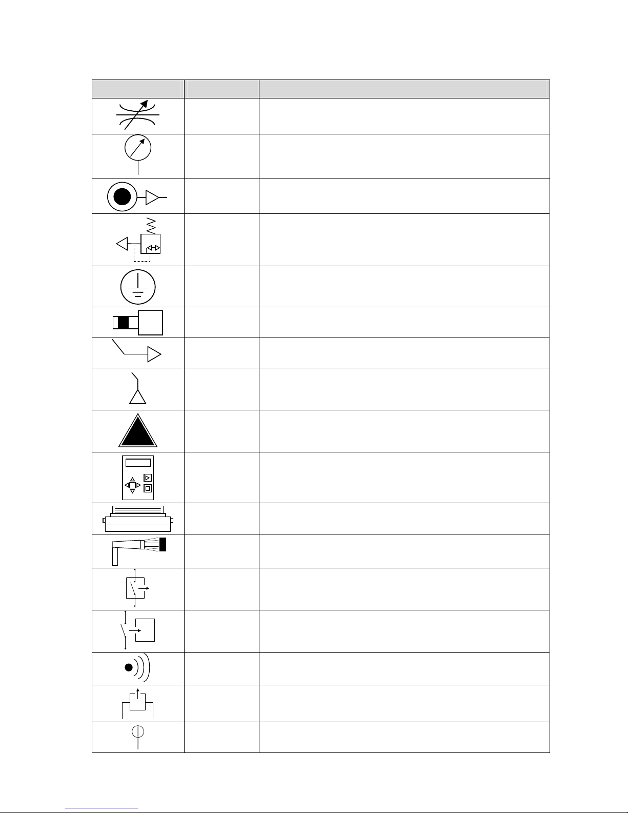
6. SYMBOLS PRESENTATION
Symbol Name Function
Adjust leak
connector
Pneumatic connector for the plugging of a calibrated leak
(ruby kind) or an adjustable leak.
Pressure
connector
Pneumatic connector for the plugging of a manometer for an
external checking of the pressure.
Pressure
supply
of the air supply from the 6 bar network.
Test circuit
supply
Pneumatic connector (according to option) for the plugging
of a supplementary pneumatic supply, used in case of test
pressure greater than 8 bar.
Ground
connector
Connector for the electric plugging to the ground.
Automatic
connector
Pneumatic connector for the driving of an external logic or
pneumatic components (pneumatic sealing connector).
Connector Connector for pneumatic output.
Connector Connector for pneumatic input.
!
Careful!
Read and respect the instructions of the user manual,
before plugging and using the instrument.
Remote
control
Connector for a remote control.
Printer Connector for printer plugging.
Bar code
reader
Connector for bar code reader plugging.
Output Dry contact output.
Input Dry contact input.
Infrared link
Infrared link, at this place there's the receiver and
transmitter of the infrared link.
Analogue
output
Analogue output.
Analogue
input
Analogue input for the temperature sensor.
Page 21
Chapter 1 – Installation of the instrument
UM-18400E-U ATEQ F580 User manual Page 11/168
Chapter 1
INSTALLATION OF THE INSTRUMENT
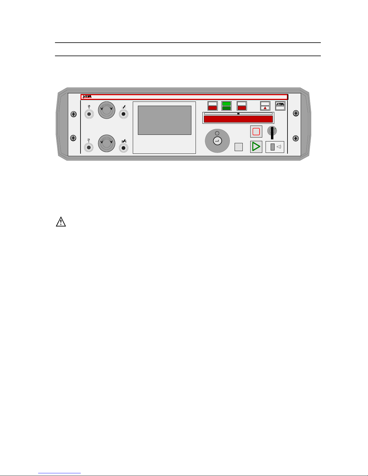
1. APPEARANCE OF THE ATEQ F580
C
CONDITIONS D'EPREUVE
RESULTAT
F580
R1 R2
!
_
+
_
+
The ATEQ F580 is supplied in a 19" case.
The instrument operates at a voltage of 90 to 260 V AC and is supplied with a power
cable.
It is essential to connect all central modules and heads to a common earth.
Use the double spade connectors provided for this purpose.
Page 22
Chapter 1 – Installation of the instrument
UM-18400E-U ATEQ F580 User manual Page 12/168
2. BASICS RECOMMENDATIONS
The network mustn't contain more than 9 (nine) measurements heads and 3
(three) I/O modules.
Before every intervention on the network, switch off the totality of the
instruments. Every manipulation of the network cables under tension can be
destructive.
The overall length of the network can't be more than 100 (one hundred)
meters.
The instruments must be insulated or moved away from all sets being able
to generate parasites (High Voltage or High Intensity) examples: welding
machines, robots, etc
The connection of the star ground is imperative between all the control units
and their heads; use the connectors with double thimbles provided for this
purpose.
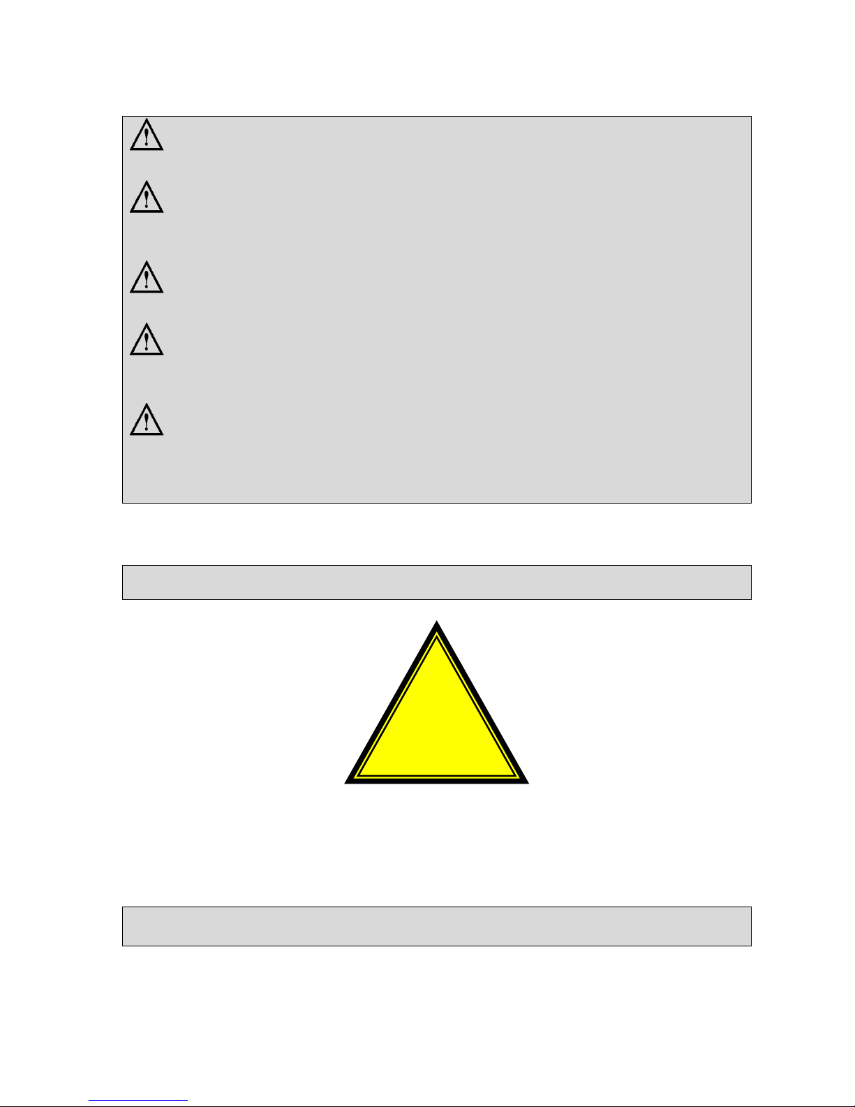
WARNING CONCERNING THIS USER MANUAL
!
The various possibilities of wiring networks
described in this user manual are valid only for
the instruments produced after:
2005 august 1st
Page 23
Chapter 1 – Installation of the instrument
UM-18400E-U ATEQ F580 User manual Page 13/168
3. INSTALLATION AND CABLING
Control unit electric supply: 90 to 260 V AC / 50W.
Measurement heads electric supply: 24 V DC (23.5 to 28 V) / 2 A by head.
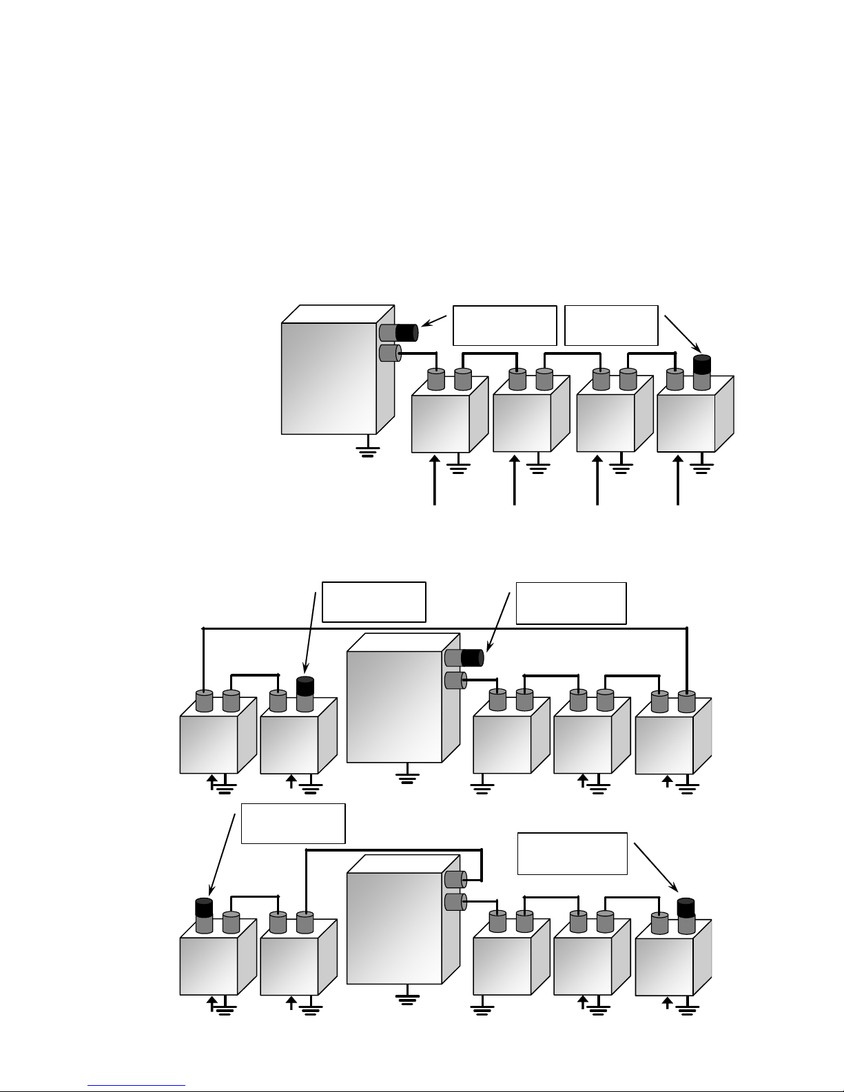
The heads electric supply can be done by three means:
¾ By the 24 V DC jack connector,
¾ By the J3 connector (Inputs/Outputs All or nothing) by the 2 or 4 pins (+24V)
and the 16 pin (0 V).
¾ On the Lumberg M12 type connector reserved to the remote control on the 2
(+24V) and 4 (0 V) pins.
The network end
caps must be
placed on the “free”
RS 485 connectors,
on the control unit
and on the last
heads.
CENTRAL
MEASUR
UNIT
N° 4
MEASUR
UNIT
N° 1
MEASUR
UNIT
N° 2
Female
network cap
Male
network cap
MEASUR
UNIT
N° 3
24 V DC
24 V DC
24 V DC
24 V DC
The control unit and the I/O module can be located at any place in the network.
3.1. CONTROL UNIT PHYSICALLY POSITIONNED BETWEEN THE HEADS
CENTRAL
HEAD
N° 4
HEAD
N° 1
HEAD
N° 2
Female
network cap
Male network
cap
24 V DC
24 V DC
24 V DC
I/O
MODULE
HEAD
N° 3
24 V DC
CENTRAL
HEAD
N° 4
HEAD
N° 1
HEAD
N° 2
Female
network cap
Male network
cap
24 V DC
24 V DC
24 V DC
I/O
MODULE
HEAD
N° 3
24 V DC
Page 24
Chapter 1 – Installation of the instrument
UM-18400E-U ATEQ F580 User manual Page 14/168
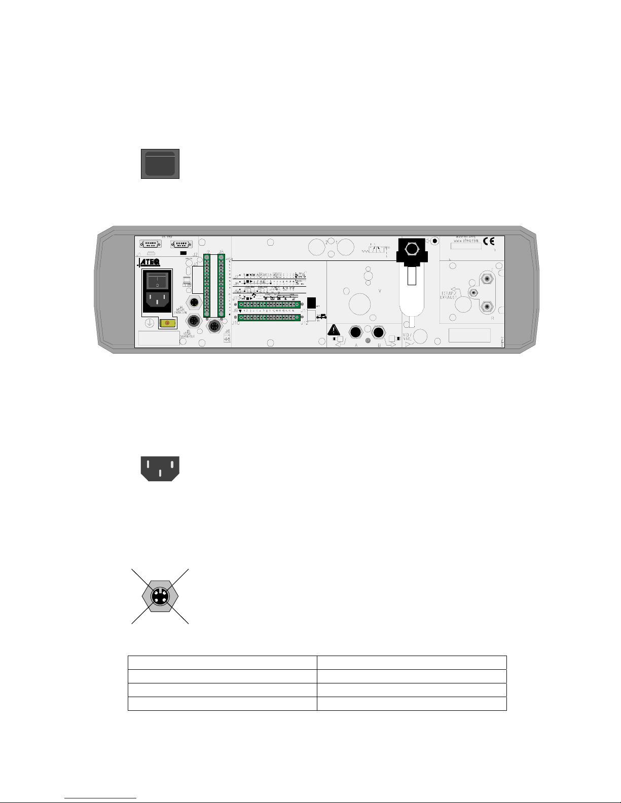
4. INSTALLATION OF THE ATEQ F580
4.1. START / STOP SWITCH
I
O
⇒ I : start
⇒ 0 : stop
4.2. L
AYOUT OF CONNECTORS ON CASE
4.3. DETAILS OF CONNECTORS
4.3.1. Electrical power supply
⇒ From 90 to 260 V AC / 50 W – 50/60 Hz
4.3.2. RS485 Link
4.3.2. 1) RS485 input connector
2 1
4
3
Allows, depending on the chosen option the connection to a
computer (PC) using an RS485 type connector.
(Lumberg type connector, male).
Pin 1 Network (D+)
Pin 2 Power + 24 V
Pin 3 Network (D-)
Pin 4 0V
Page 25
Chapter 1 – Installation of the instrument
UM-18400E-U ATEQ F580 User manual Page 15/168
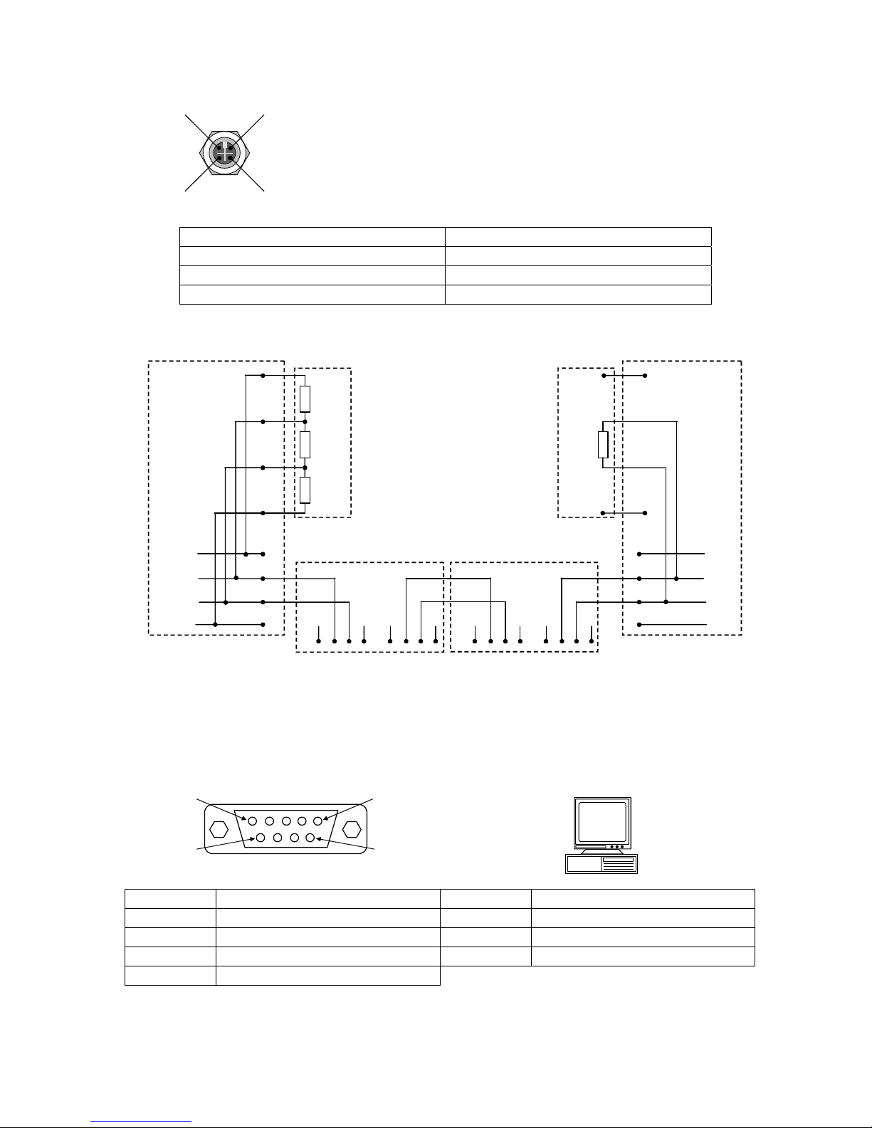
4.3.2. 2) RS485 output connector
2
1
4
3
Allows, depending on the chosen option the connection to a
computer (PC) using an RS485 type connector.
(Lumberg type connector, female).
Pin 1 Network
Pin 2 Power + 24 V
Pin 3 Network
Pin 4 0V
4.3.2. 3) Network cabling drawing
First element
Last element
2
1
3
4
120
2 4
470
Ground 0V
4,7k
120
3
1
2
4
+24V
Network D+
Network D-
3
1
2
4
Femelle
cap
1 3 2413 2413 2413
Ground 0V
+24V
Network D+
Network D-
3
1
2
4
Second element Third element
Male
cap
4.3.3. NETWORK supervision
The control unit can be connected to a supervisor PC type with Winateq type software
by the RS232 connector dedicated or by a Profibus, Modbus or DeviceNet fieldbus
network.
4.3.3. 1) RS232 link (PC – Modbus)
1
6
5
9
SubD 9 pins male base
Pin 1 Not used Broche 6 + 5V DC 200 mA maximum.
Pin 2 RXD Data reception Broche 7 RTS request to send
Pin 3 TXD Data emission Broche 8 CTS clear to send
Pin 4 Not used Broche 9 Not used
Pin 5 Ground
Page 26
Chapter 1 – Installation of the instrument
UM-18400E-U ATEQ F580 User manual Page 16/168
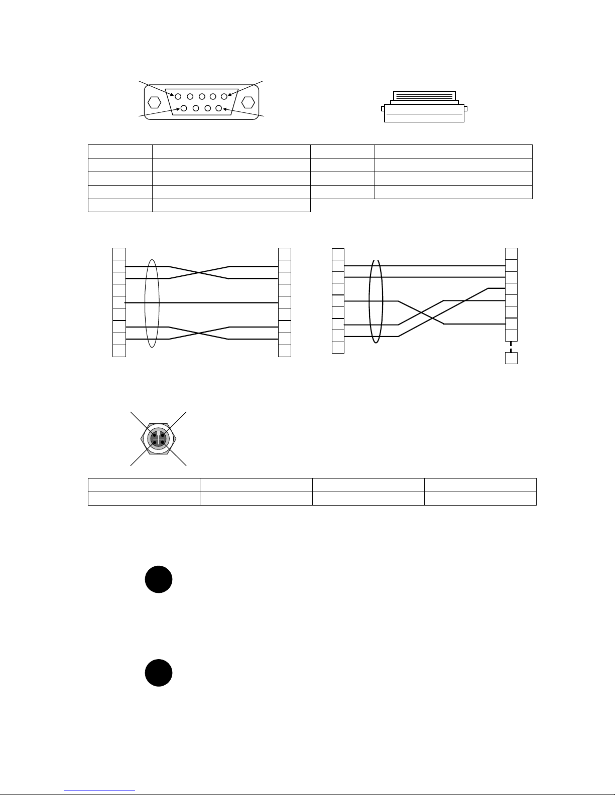
4.3.3. 2) Printer link
1
6
5
9
SubD 9 pins male base
Pin 1 Not used Pin 6 Not used
Pin 2 RXD Data reception Pin 7 RTS request to send
Pin 3 TXD Data emission Pin 8 CTS clear to send
Pin 4 Not used Pin 9 Not used
Pin 5 Ground
4.3.3. 3) Examples of RS232 cables
1
2
3
4
5
6
7
8
9
1
2
3
4
5
6
7
8
9
ATEQ
Operator
9 pin SubD
connector
9 pin SubD
connector
RX
TX
GND
RTS
CTS
RX
TX
GND
RTS
CTS
1
2
3
4
5
6
7
8
9
1
2
3
4
5
6
7
8
ATEQ
Operator
25
9 pin SubD
connector
25 pin SubD
connector
RX
TX
GND
RTS
CTS
RX
TX
GND
RTS
CTS
4.3.4. J6 connector RS232 (remote control)
2
1
4
3
For connection of an intelligent remote control.
(Lumberg type female connector).
Pin 1 Network (TXD) Pin 3 Network (RXD)
Pin 2 + 24V voltage Pin 4 0V Earth / Ground
4.3.5. Central "PIN service" button
In the event of Winateq network management, this button
allows the confirmation of the centrals’ presence in the
network.
4.3.6. Head "PIN service" button
This button allows the confirmation of the heads' presence in
tne network in the hoped order.
Page 27
Chapter 1 – Installation of the instrument
UM-18400E-U ATEQ F580 User manual Page 17/168
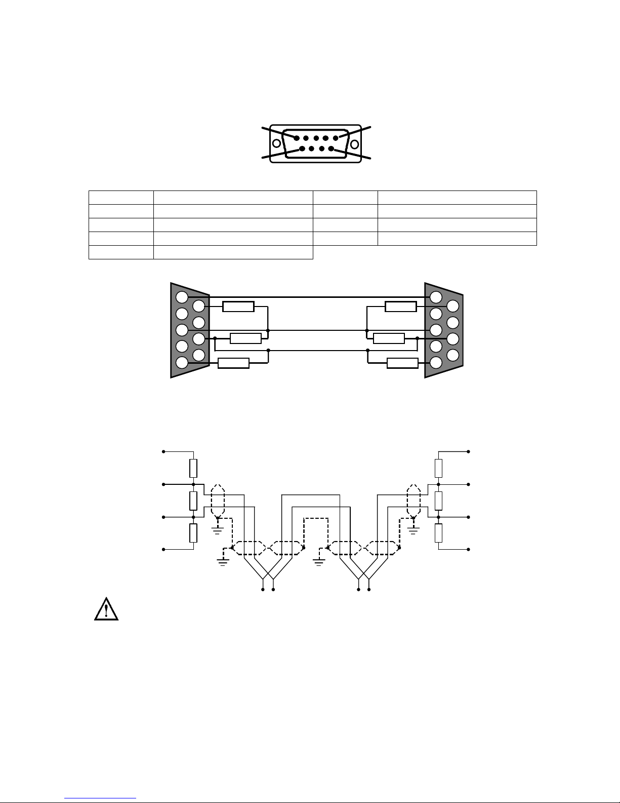
4.3.7. Profibus fieldbus network
4.3.7. 1) J3 Connector
1
5
9
6
SubD 9 pins female base
Pin 1 Earth Pin 6 VP (Supply)
Pin 2 Not use Pin 7 Not use
Pin 3 Data A Pin 8 Data B
Pin 4 CNTR-A Pin 9 Not use
Pin 5 Digital ground
4.3.7. 2) Profibus wiring
Profibus cable
1
2
3
4
5
6
7
8
9
1
2
3
4
5
6
7
8
9
390 Ω
390 Ω
110 Ω
390 Ω
110 Ω
390 Ω
4.3.7. 3) Network wiring drawing
First element
Last element
VP
6
3
8
5
390
220
390
DGND
3 388
390
DGND
390
220
8
3
6
5
VP
Data A
B
A
B
A
Data B Data B
Data A
When the instrument is considered as the first or the last element of the network, it
must have terminations resistors in the cable connector. The cable supplied by ATEQ
has the resistors on each connector and can be used on a configuration with only 2
instruments: a master and a slave.
Page 28
Chapter 1 – Installation of the instrument
UM-18400E-U ATEQ F580 User manual Page 18/168
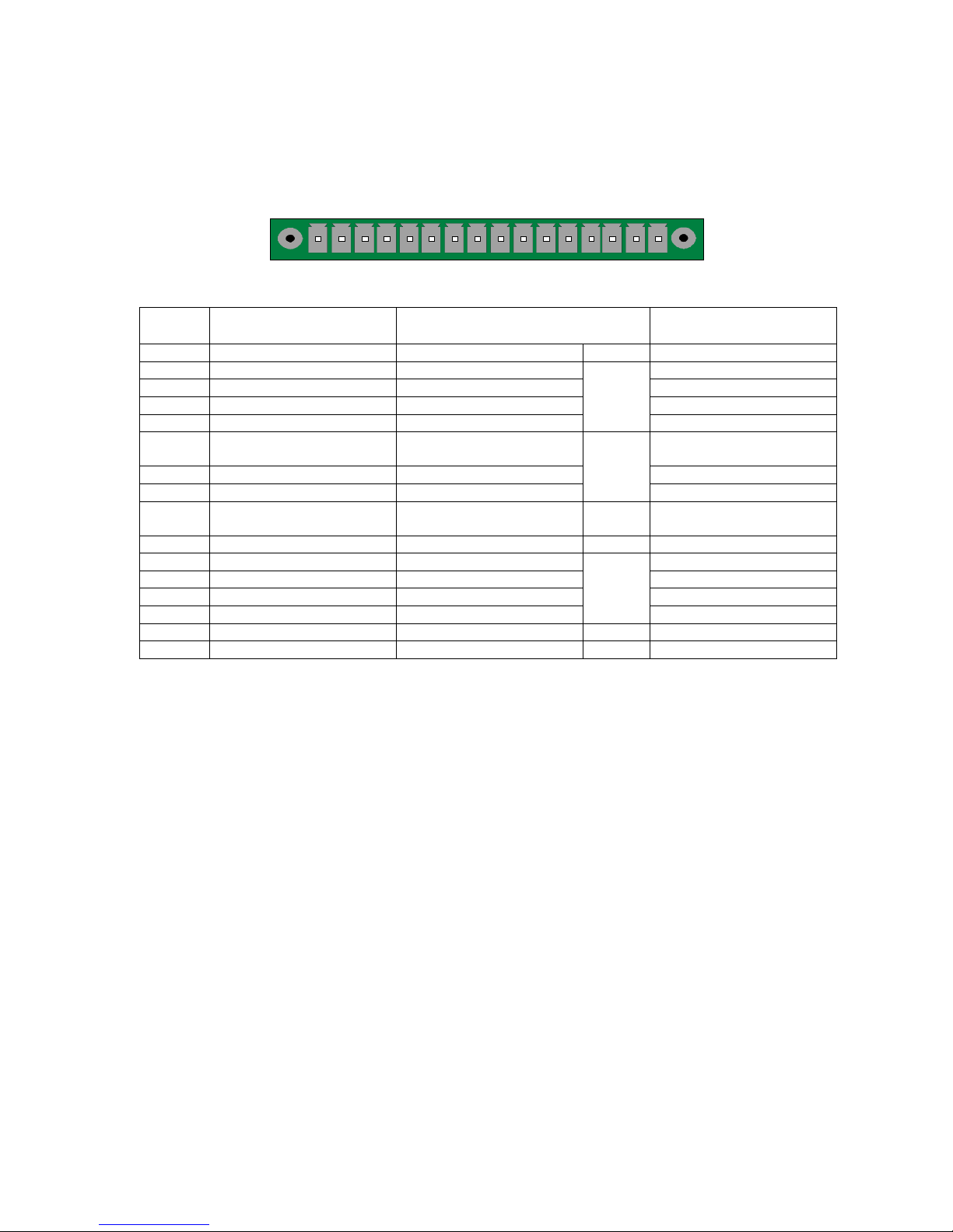
4.3.8. J7 outputs connector
The “All or nothing” outputs can be set according to three different configurations,
extended mode, standard mode or compact mode. Refer to chapter 3, paragraph 3
"Allocation of the outputs".
1 2 3 4 5 6 7 8 9 10111213141516
60 V AC/DC maximum, 200 mA maximum VOLT FREE OUTPUTS
Pin
Extended mode Standard mode Compact mode
1 COMMON (outputs 2 to 8) COMMON (outputs 2 to 8) COMMON (outputs 2 to 8)
2 Pass Head 1 Pass Head 1 Pass
3 Test part fail Head 1 Fail Head 2 Pass
4 Reference part fail Head 1 alarm Head 3 Pass
5 Alarm Head 1 end of cycle
Bloc 1
Head 4 Pass
6
Pressure regulator fault
(pressure outside limits)
Head 2 Pass Head 5 Pass
7 End of cycle Head 2 Fail Head 6 Pass
8 Recoverable parts Head 2 alarm
Bloc 2
Head 7 Pass
9
COMMON (outputs 10 to
16)
COMMON (outputs 10 to
16)
COMMON (outputs 10 to
16)
10 Customer calibration fault Head 2 end of cycle Bloc 2 Head 8 Pass
11 Auto-diagnostic fault Head 3 Pass Head 9 Pass
12 ATR fault Head 3 Fail Reserved
13 Free Head 3 alarm Reserved
14 Free Head 3 end of cycle
Bloc 3
Reserved
15 Free Global end of cycle Global end of cycle
16 Free Special cycle fault Alarm
4.3.9. Allocation of the outputs
The "extended" mode allows the allocation of all the J7 connector outputs to a
measurement unit (head). This extended mode is valid if the number of I/O modules is
equal to the number of measurement units. This enables the linking of all outputs to one
measurement unit. This configuration is interesting as it gives all the useful information
concerning a measurement unit.
The "standard" mode allows the allocation of a maximum of three measurement units
per I/O module. The information of each unit is communicated in packs on the outputs
of an I/O module. The information is summarised (part good, part bad, warning and end
of cycle). In this mode the allocation address of measurement units 1, 2 and 3
respectively on packs 1, 2 and 3 can be modified. For example unit 1 on block 3, unit 2
on block 1 and unit 3 on block 2.
The "compact" mode enables the recovery of information from 9 measurement units
on a single I/O module, the information sent is limited to part good, global end of cycle
and warning. This mode is useful if the number of measurement units is much greater
than the number of I/O modules or to limit the number of I/O modules.
Note: in standard or compact mode a START without unit selection starts all the units.
Page 29
Chapter 1 – Installation of the instrument
UM-18400E-U ATEQ F580 User manual Page 19/168
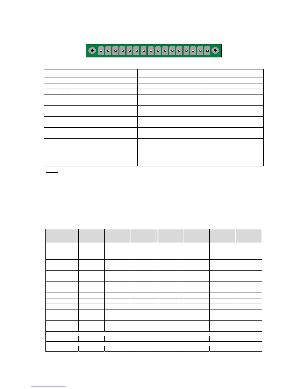
4.3.10. J8 inputs connector
1 2 3 4 5 6 7 8 9 10111213141516
VOLT FREE OR CNOMO INPUTS DEPENDING ON CONFIGURATION
Pin Extended mode Standard mode Compact mode
1 COMMON negative COMMON negative COMMON negative
2 E1 Stop cycle (RESET) Stop cycle (RESET) Stop cycle (RESET)
3 E2 Start cycle (start) Start cycle (start) Start cycle (start)
4 E3 ATR request Select head 1 Select head 1
5 E4 Auto-diagnostic check request Select head 2 Select head 2
6 E5 Customer calibration request Select head 3 Select head 3
7 E6 Auto zero request Select Program 2 Select Program 2
8 E7 Manual / Automatic Select Program 3 Select Program 3
9 COMMON negative COMMON negative COMMON negative
10 E8 Select Program 2 Select Program 5 Select Program 5
11 E9 Select Program 3 Select Program 9 Select Program 9
12 E10 Select Program 5 Select Program 17 Select Program 17
13 E11 Select Program 9 Select Program 33 Select Program 33
14 E12 Select Program 17 ATR request ATR request
15 E13 Select Program 33 Check calibration request Check calibration request
16 E14 Not used Calibration request Calibration request
Note: in the event of standard mode configuration, the simultaneous activation of pins
14, 15 and 16 causes an auto-zero request of the units selected.
4.3.10. 1) Activating a program from the J8 connector inputs
a) Extended mode
In extended mode, to activate a program from the J8 connector inputs, you have to
select pins 10 to 16 (one or more). Binary weight n + 1.
Pin combinations for program selection
Program
number
Pin 10
(input 8)
Pin 11
(input 9)
Pin 12
(input 10)
Pin 13
(input 11)
Pin 14
(input 12)
Pin 15
(input 13)
Pin 16
(input 14)
1 0 0 0 0 0 0 0
2
1
0 0 0 0 0 0
3 0
1
0 0 0 0 0
4
1 1
0 0 0 0 0
5 0 0 1 0 0 0 0
6
1
0
1
0 0 0 0
7 0
1 1
0 0 0 0
8
1 1 1
0 0 0 0
9 0 0 0
1
0 0 0
10
1
0 0
1
0 0 0
11 0
1
0
1
0 0 0
12
1 1
0
1
0 0 0
13 0 0
1 1
0 0 0
14
1
0
1 1
0 0 0
15 0
1 1 1
0 0 0
16
1 1 1 1
0 0 0
Prgm select 17
x x x x
1
x x
Prgm select 33
x x x x x
1
x
With x who takes the 0 or 1 value in function of the program number to be called.
Page 30

Chapter 1 – Installation of the instrument
UM-18400E-U ATEQ F580 User manual Page 20/168
b) Standard or compact mode
In standard or compact mode, to activate a program from the J8 connector inputs, you
have to select pins 7, 8, 10, 11, 12 and 13 (one or more). Binary weight n + 1.
Pin combinations for program selection
Program
number
Pin 7
(input 6)
Pin 8
(input 7)
Pin 10
(input 8)
Pin 11
(input 9)
Pin 12
(input 10)
Pin 13
(input 11)
1 0 0 0 0 0 0
2
1
0 0 0 0 0
3 0
1
0 0 0 0
4
1 1
0 0 0 0
5 0 0 1 0 0 0
6
1
0
1
0 0 0
7 0
1 1
0 0 0
8
1 1 1
0 0 0
9 0 0 0
1
0 0
10
1
0 0
1
0 0
11 0
1
0
1
0 0
12
1 1
0
1
0 0
13 0 0
1 1
0 0
14
1
0
1 1
0 0
15 0
1 1 1
0 0
16
1 1 1 1
0 0
Program
selection 17
x x x x
1
x
Program
selection 33
x x x x x
1
With x who takes the 0 or 1 value in function of the program number to be called.
Page 31
Chapter 1 – Installation of the instrument
UM-18400C-U ATEQ F580 User manual Page 21/168
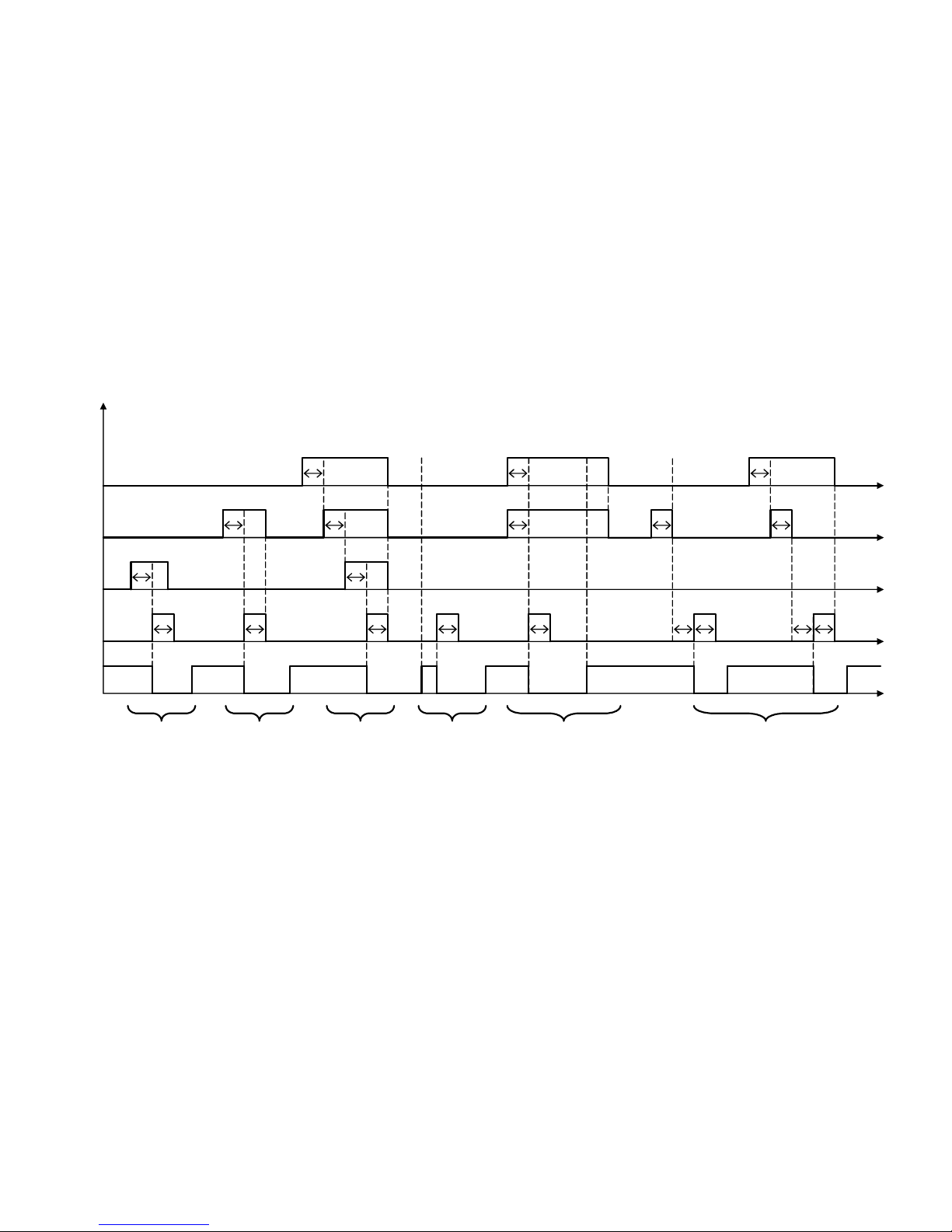
4.3.11. J8 connector inputs planner
Start
End of
cycle
t
t
t
t
t
t
t
t
t
t
t
t tt
t
tt
t
t
Selection
head 3
Selection
prog 2
ATR
request
or CAL
or calib
ATR request…
on all the measurment
units (heads) in the
active programme of
each unit (or head)
Cycle on the program
N° 2 of all m. units
ATR request…
in the program N° 2 of
the m. unit N° 3
General start cycle in
the active program of
each m. unit (here the
unit N°3 stays in the
program N° 2)
Be carefull, al l m.
units come back to
the program N°1
An impulse on any selection program
inputs, out of cycle, allows to activate
the program N°1 on all the m. units or
on the selected m. unit, in this case the
start cycle can be done only 0,5 s after
the end of the impulse.
¾ t = 0,5 sec minimum
¾ In the above example it be considered that all the inputs not listed are standing
Page 32
Chapter 1 – Installation of the instrument
UM-18400E-U ATEQ F580 User manual Page 22/168
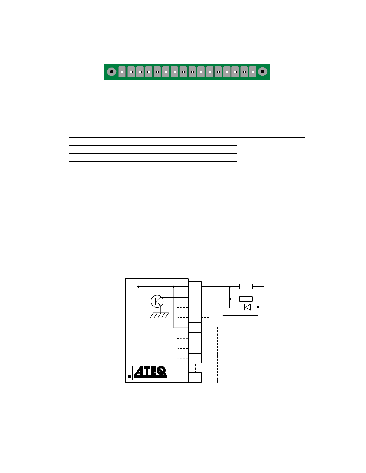
4.3.12. J9 and J10 connector
1 2 3 4 5 6 7 8 9 10111213141516
Depending on the required configuration, the boards may be a relay board, or an output
code board applied to any connector (J9 or J10) and each board may be assigned to
head number 1 or 2.
4.3.12. 1) Output codes board
Output codes / analogue outputs / temperature transducers :
PIN 1 COMMON (outputs 1, 2, 3) + 24 V DC
PIN 2 Output n°1, open collector
PIN 3 Output n°2, open collector
PIN 4 Output n°3, open collector
PIN 5 COMMON (outputs 4, 5, 6) + 24 V DC
PIN 6 Output n°4, open collector
PIN 7 Output n°5, open collector
PIN 8 Output n°6, open collector
OUTPUT CODES
24V DC 100mA Max
Outputs
PIN 9 12V Sensor power supply
PIN 10 0V Sensor power supply
PIN 11 SENSOR n°1 input
PIN 12 SENSOR n°2 input
TEMPERATURE
SENSORS
PIN 13 Analogue outputs n°1
PIN 14 COMMON (analogue output 1)
PIN 15 Analogue output n°2
PIN 16 COMMON (analogue output 2)
ANALOGUE
OUTPUTS
* Options.
24 V DC
8
7
6
5
4
3
2
1
0,1 A max
Charge / Load
Obligatory
diode for an
inductive load.
Page 33
Chapter 1 – Installation of the instrument
UM-18400E-U ATEQ F580 User manual Page 23/168
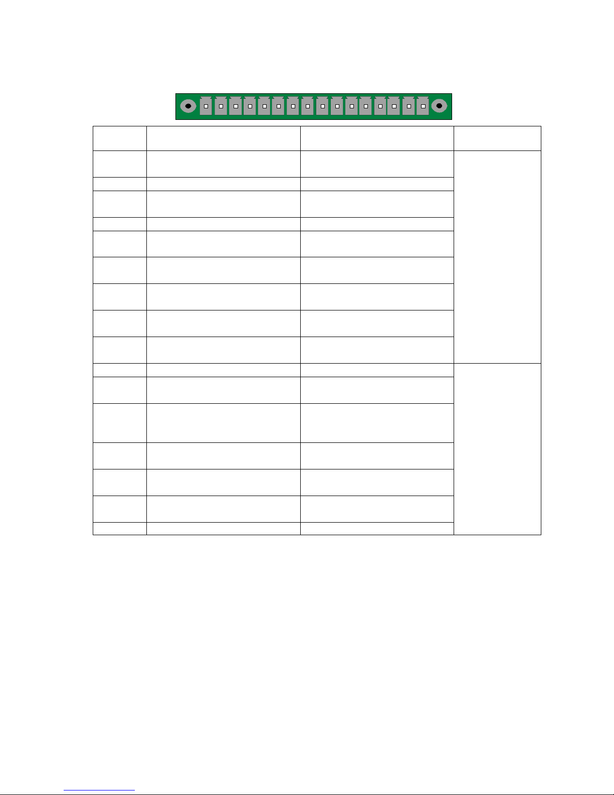
4.3.12. 2) Relay board 16 programs
1 2 3 4 5 6 7 8 9 10111213141516
Pin Standard mode Compact mode
1
Input 1
Reset
Input 1
Reset
2 Common (+ 24 V) Common (+ 24 V)
3
Input 2
START
Input 2
START
4 Common (+ 24 V) Common (+ 24 V)
5
Input 3
Program selection
Input 3
Program selection
6
Input 4
Program selection
Input 4
Program selection
7
Input 5
Program selection
Input 5
Program selection
8
Input 6
Program selection
Input 6
Program selection
9
Input 7
Program selection
Input 7
Program selection
INPUTS
(Activation by
24 V DC)
Common
+ 24 V = 0,3 A
maxi
10 Floating common output Floating common output
11
Output 1
Pass part
Output 1
Pass part cycle 1
12
Output 2
Test error
Output 2
Fail part
cycle 1 + alarm
13
Output 3
Reference error
Output 3
Pass part cycle 2
14
Output 4
Alarm
Output 2 Fail part
cycle 2 + alarm
15
Output 5
Fin de cycle
Output 5
Fin de cycle
16 0 V 0 V
DRY
CONTACT
OUTPUTS
60V AC / DC
Max
200mA Max
The compact mode is a software function which is activated in the CONFIGURATION /
CHANGE I/O / OUTPUT menu.
Page 34

Chapter 1 – Installation of the instrument
UM-18400E-U ATEQ F580 User manual Page 24/168
4.3.12. 3) Activating a program from the J9 or J10 relay board
inputs 16 programs
To activate a program from the J9 or J10 connector inputs, you have to select pins 5 to
9 (one or more). Binary weight n + 1.
Pin combinations for program selection
Program
number
Pin 5
(Input 3)
Pin 6
(Input 4)
Pin 7
(Input 5)
Pin 8
(Input 6)
Pin 9
(Input 7)
1 0 0 0 0 0
2 1 0 0 0 0
3 0 1 0 0 0
4 1 1 0 0 0
5 0 0 1 0 0
6 1 0 1 0 0
7 0 1 1 0 0
8 1 1 1 0 0
9 0 0 0 1 0
10 1 0 0 1 0
11 0 1 0 1 0
12 1 1 0 1 0
13 0 0 1 1 0
14 1 0 1 1 0
15 0 1 1 1 0
16 1 1 1 1 0
4.3.12. 4) J9 or J10 Connectors (I/O inputs/outputs) programmable
input
Input 7 (pin 9) parameters can be set in the CONFIGURATION/CHANGE I/O menu.
The functions which can be programmed and are available on this input are all the
specials cycle:
9 Program selection.
9 Regulator 1 adjust request.
9 Regulator 2 adjust request.
9 Infinite fill request.
9 Piezo auto zero request.
9 Pass part sealed component learn request.
9 Fail part sealed component learn request.
9 Calibration check by volume request.
9 Custom unit learn request.
9 Custom unit check request.
9 ATR learning cycle request.
9 Volume calculation request.
Some possibilities appear only if the function is used.
Page 35
Chapter 1 – Installation of the instrument
UM-18400E-U ATEQ F580 User manual Page 25/168
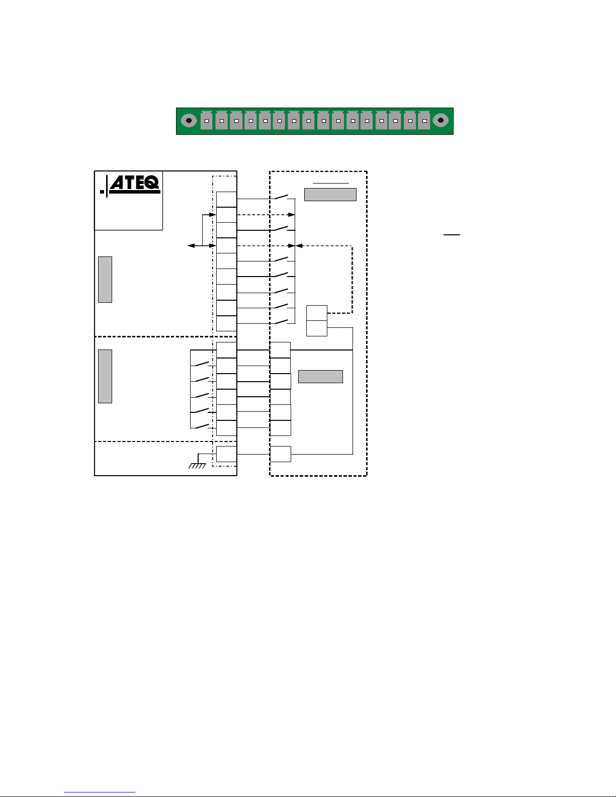
4.3.13. J9 or J10 Connector (I/O inputs/outputs) drawing
1 2 3 4 5 6 7 8 9 10111213141516
a) PLC in NPN mode connection
I1 (Reset)
Customer
Input boards
16/32 programs
I
2
(Start)
I
3
(Pr 1 + 1)
I
4
(Pr 2 + 1)
Good part
Common
Test fail part
Reference fail part
Alarm
End of cycle
24 V DC
24 V DC
ATEQ or customer
I6 (Pr 8 + 1)
I
5
(Pr 4 + 1)
I
7
(Programmable input)
16
15
14
13
12
11
10
9
8
7
6
5
4
3
2
1
NPN MODE
Ground
+ 24 V DC
J3
INPUTS OUTPUTS
OUTPUTS
+
-
INPUTS
Customer
0 V
(0,3 A max)
Note: The 24V power supply
must be provided by the
internal power supply of the
ATEQ instrument (0,3A
maximum) OR through an
external power supply provided
by the customer.
In the case of customer
external supply, the ATEQ
instrument can be supply by
the 2 and 4 pins on the J3
connector too.
Page 36
Chapter 1 – Installation of the instrument
UM-18400E-U ATEQ F580 User manual Page 26/168
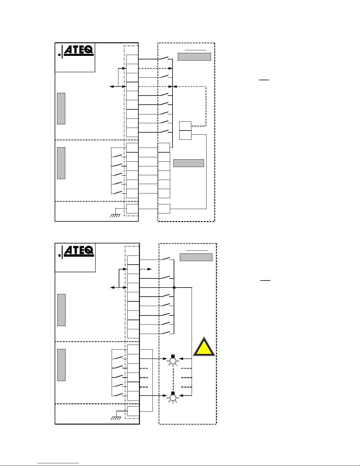
b) PLC in PNP mode connection
I1 (Reset)
Customer
Inputs board
16/32 programs
I
2
(Start)
I
3
(Pr 1 + 1)
I
4
(Pr 2 + 1)
Good part
Common
Test fail part
Reference fail part
Alarm
End of cycle
24 V DC
24 V DC
ATEQ or customer
I6 (Pr 8 + 1)
I
5
(Pr 4 + 1)
I
7
(Programmable input)
16
15
14
13
12
11
10
9
8
7
6
5
4
3
2
1
PNP MODE
Ground
+ 24 V DC
J3
INPUTS OUTPUTS
OUTPUTS
+
-
INPUTS
Customer
0 V
(0,3 A max)
Note: The 24V power supply
must be provided by the
internal power supply of the
ATEQ instrument (0,3A
maximum) OR through an
external power supply provided
by the customer.
In the case of customer
external supply, the ATEQ
instrument can be supply by
the 2 and 4 pins on the J3
connector too.
c) Lights connection
I1 (Reset)
Customer
Inputs board
16/32 programs
I
2
(Start)
I
3
(Pr 1 + 1)
I
4
(Pr 2 + 1)
Good part
Common
Test fail part
Reference fail part
Alarm
End of cycle
24 V DC
I6 (Pr 8 + 1)
I
5
(Pr 4 + 1)
I
7
(Programmable input)
16
15
14
13
12
11
10
9
8
7
6
5
4
3
2
1
Ground
+ 24 V DC
J3
INPUTS OUTPUTS
OUTPUTS
0,3 A Max
with ATEQ
24 V DC
!
0,2 A
Max
0,2 A
Max
(0,3 A max)
Note: The 24V power supply
must be provided by the
internal power supply of the
ATEQ instrument (0,3A
maximum) OR
through an
external power supply
provided by the customer.
In the case of customer
external supply, the ATEQ
instrument can be supply by
the 2 and 4 pins on the J3
connector too.
Page 37

Chapter 1 – Installation of the instrument
UM-18400E-U ATEQ F580 User manual Page 27/168
4.3.13. 2) J11 connector
Telephone network socket. Not used.
4.3.13. 3) J12 input connector (24 V)
Not used.
4.3.14. Pneumatic connectors
4.3.14. 1) Automatic connector A
For pneumatic control of a sealing connection.
4.3.14. 2) Automatic connector B
For pneumatic control of a second sealing connection.
4.3.14. 3) Pneumatic inputs/outputs
⇒ Reference output.
⇒ Pressurisation output.
R
T
⇒ Test output.
These outputs are for connection of parts (test, reference). The pressurisation output is
used for the addition of
ATEQ accessories (Y valve).
Page 38

Chapter 1 – Installation of the instrument
UM-18400E-U ATEQ F580 User manual Page 28/168
4.3.14. 4) Pneumatic supply
Air supply is via the filter located on the rear panel of the
instrument.
Note: when an electronic regulator is used with test
pressures above 800 kPa (8 bar) (normal service
pressure), another "high pressure" input for the test
circuit is installed on the instrument.
It is essential that the air supplied is clean and dry. Even though there is a filter,
supplied with the instrument, the presence of dust, oil or impurities may cause
malfunction.
When the instrument is working in vacuum conditions, impurities must be prevented
from being drawn into its interior. For this purpose we strongly recommend that a
suitable airtight filter is installed between the test part and the instrument. This filter can
be supplied by
ATEQ.
The presence of impurities, oil or humidity in the air may cause deterioration which will
not be covered by the guarantee.
In accordance with ISO standard 8573-1 concerning classes of compressed air for
measurement instruments in an industrial environment :
ATEQ recommends :
• Grain size and concentration CLASS 1 (0.1 µm and 0.1 mg/m
3
)
• Dew point under pressure CLASS 2 (- 40° dew)
• Maximum concentration of oil CLASS 1 (0.01 mg/m
3
)
ATEQ recommends the installation :
• of an air dryer to provide dry air at less than - 40° dew point,
• of a 25 micron and 1/100 micron double filter.
Optimisation of operation :
The supply pressure must always be between 4 and 8 bar to ensure that the pneumatic
distributors operate with optimum efficiency.
When a mechanical regulator is used, the supply pressure must be a minimum of
100 kPa (1 bar) greater than test pressure with a minimum of 400 kPa (4 bar).
When an electronic regulator is used, the regulator input pressure must be
at least 10 % greater than full scale value of the electronic regulator
+ 100 kPa (+ 1 bar).
Page 39
Chapter 2 – User interfaces
UM-18400E-U ATEQ F580 User manual Page 29/168
Chapter 2
USER INTERFACES
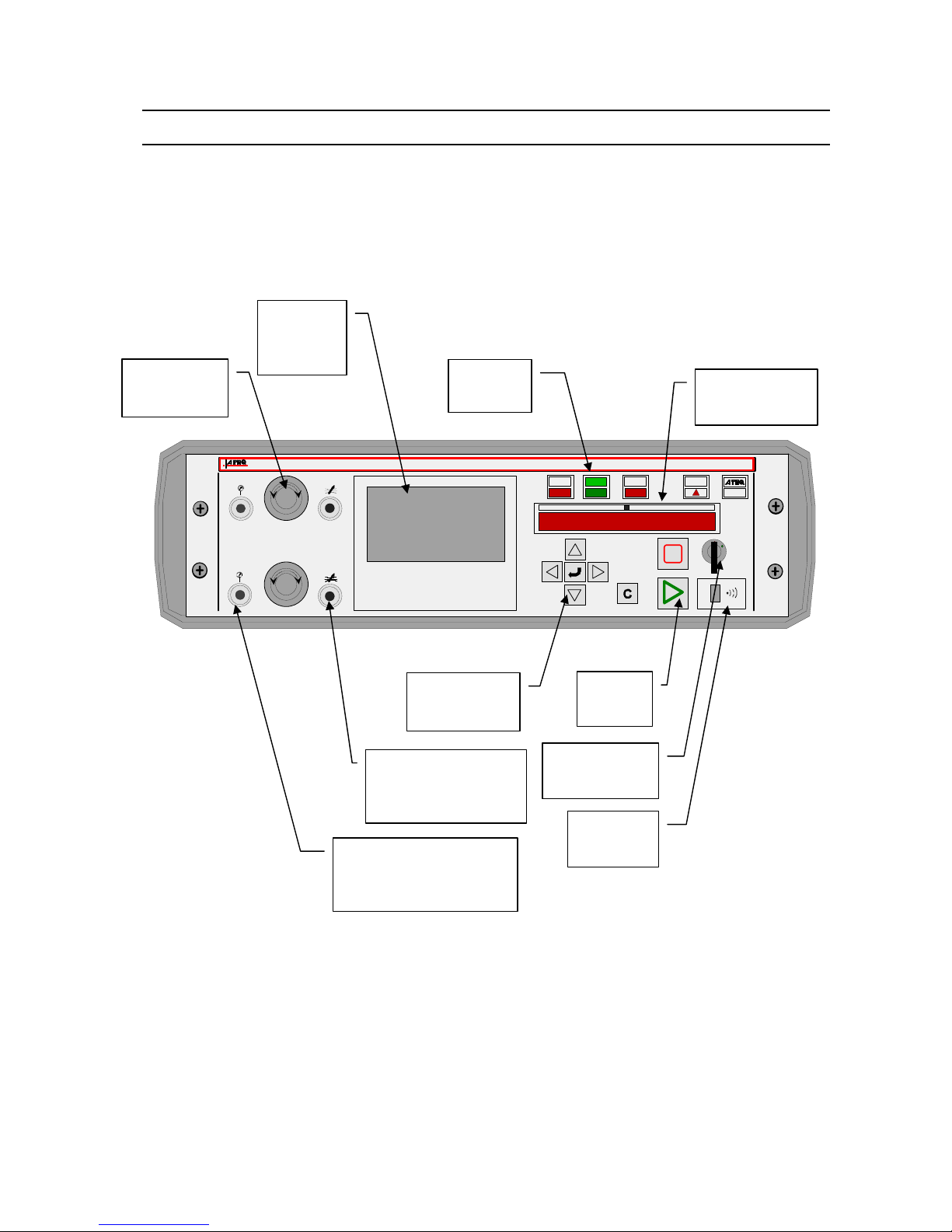
1. APPEARANCE OF FRONT PANEL OF ATEQ F580
CONDITIONS D'EPREUVE
RESULTAT
F580
R1 R2
!
_
+
_
+
16 lines
LCD
display
Results
display
14 character
LED display
Navigation
keys
Cycle
keys
Leak
measurement
quick connector
Pressure
measurement quick
connector
Pressure
regulators
Access /
lock switch
Infrared
receiver
Page 40
Chapter 2 – User interfaces
UM-18400E-U ATEQ F580 User manual Page 30/168
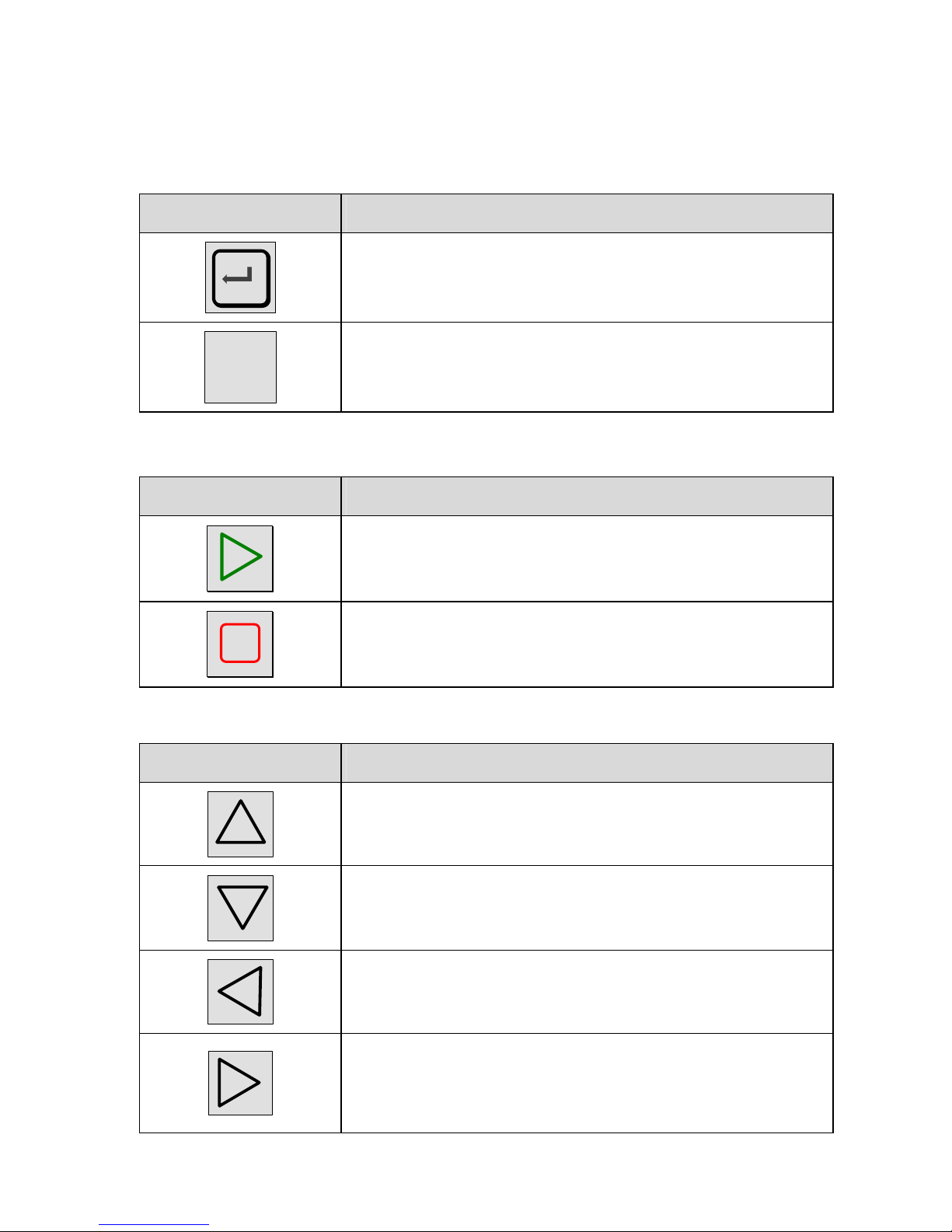
2. APPEARANCE OF KEYBOARD
2.1. VALIDATION AND ESCAPE KEYS
KEY FUNCTION
ENTER key: entering a menu, editing a parameter
, validating a parameter
C
« C » for CANCEL: return to previous menu or function,
escape without modifying a parameter
2.2. CYCLE KEYS
KEY FUNCTION
DEPART key
Starting a measurement cycle
RAZ key (Reset to zero)
Stopping current measurement cycle
2.2.1. Navigation keys
KEY FUNCTION
Scroll up or
increase numerical values
Scroll down or decrease numerical values
Movement across to the left in the central module main menu.
Movement of the comer to the left when setting numerical
values.
Movement across to the right in the central module main
menu.
Movement of the comer to the right when setting numerical
values.
Page 41
Chapter 2 – User interfaces
UM-18400E-U ATEQ F580 User manual Page 31/168
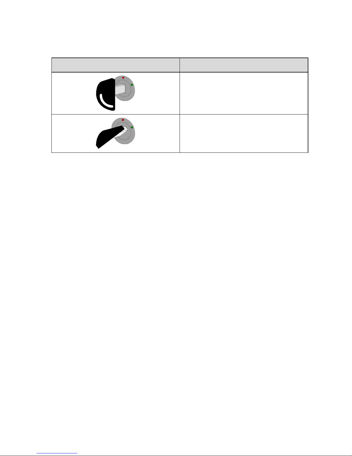
3. LOCK SWITCH
POSITION FUNCTION
LOCKED position
No access to adjustable parameters
ACCESS position.
Access to adjustable parameters
Note : it is possible to start and stop test cycles whatever the position of the lock switch
(LOCKED or ACCES).
Page 42
Chapter 2 – User interfaces
UM-18400E-U ATEQ F580 User manual Page 32/168
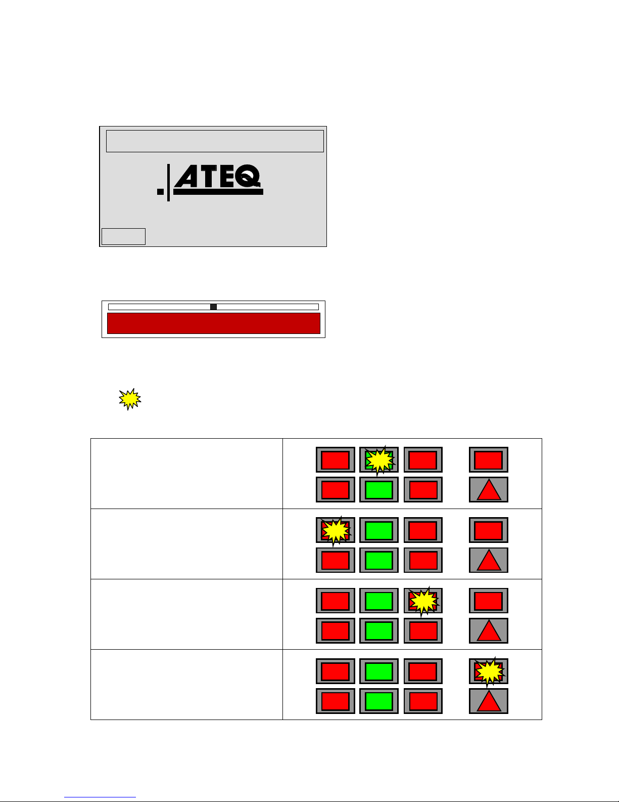
4. DISPLAYS AND LIGHTS
4.1. 16 LINE LCD DISPLAY
C 540 Vx.xxi
NETWORK LANGUAGE RUN
Used to display measurements and
adjustable parameters. In the example
opposite, X.XXi represents the
program version for the instrument.
4.2. 14 CHARACTER LED DISPLAY
CONDITIONS D'EPREUVE
RESULTAT
Displays measurements.
4.3. MEANINGS OF INDICATOR LIGHTS
The symbol indicates a lit indicator light.
Example for a pneumatic type head.
Pass indicator light
R2 R1
Test Part Fail indicator light
R2 R1
Reference Part Fail indicator light
R2 R1
Alarm
(indicator light flashing)
R2 R1
Page 43
Chapter 2 – User interfaces
UM-18400E-U ATEQ F580 User manual Page 33/168
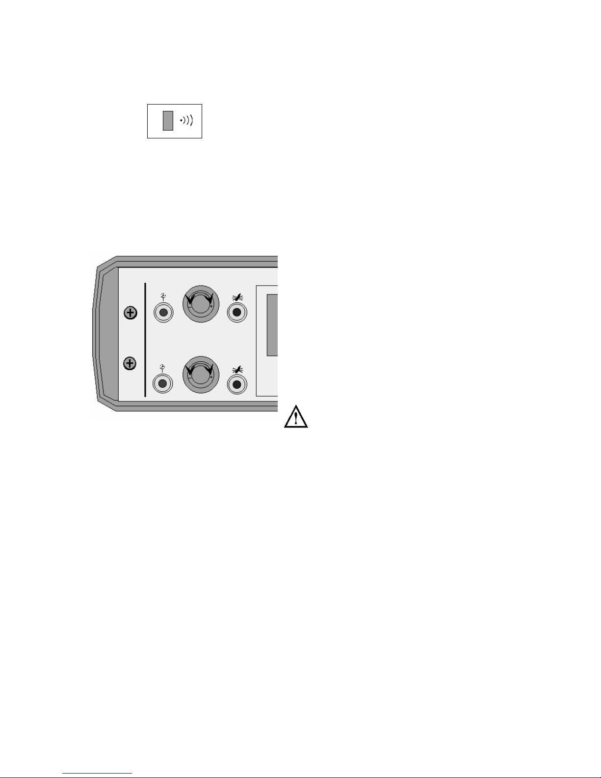
5. INFRARED INTERFACE
Not functional.
6. RAPID CONNECTORS
Rapid connectors may be mounted on the front
of the instrument. They enable the pressure
and calibration to be verified easily. The first is
used for the regulator circuit and enables the
value of the test pressure indicated by the
instrument to be checked with a standard gauge
or the ATEQ Leak flow calibrator. This
connector is not part of the measurement circuit
and does not interfere with the test.
The second is used for verification of the test
circuit and uses a known standard leak
expressed in cm3/min or another unit of flow to
find the equivalent drop in pressure and, if
necessary, to calibrate in this unit.
Because this connector is part of the
measurement circuit, all connections to it
must be airtight.
Page 44

Chapter 2 – User interfaces
UM-18400E-U ATEQ F580 User manual Page 34/168
Page 45
Chapter 3 – Start-up and settings
UM-18400E-U ATEQ F580 User manual Page 35/168
Chapter 3
START-UP AND SETTINGS
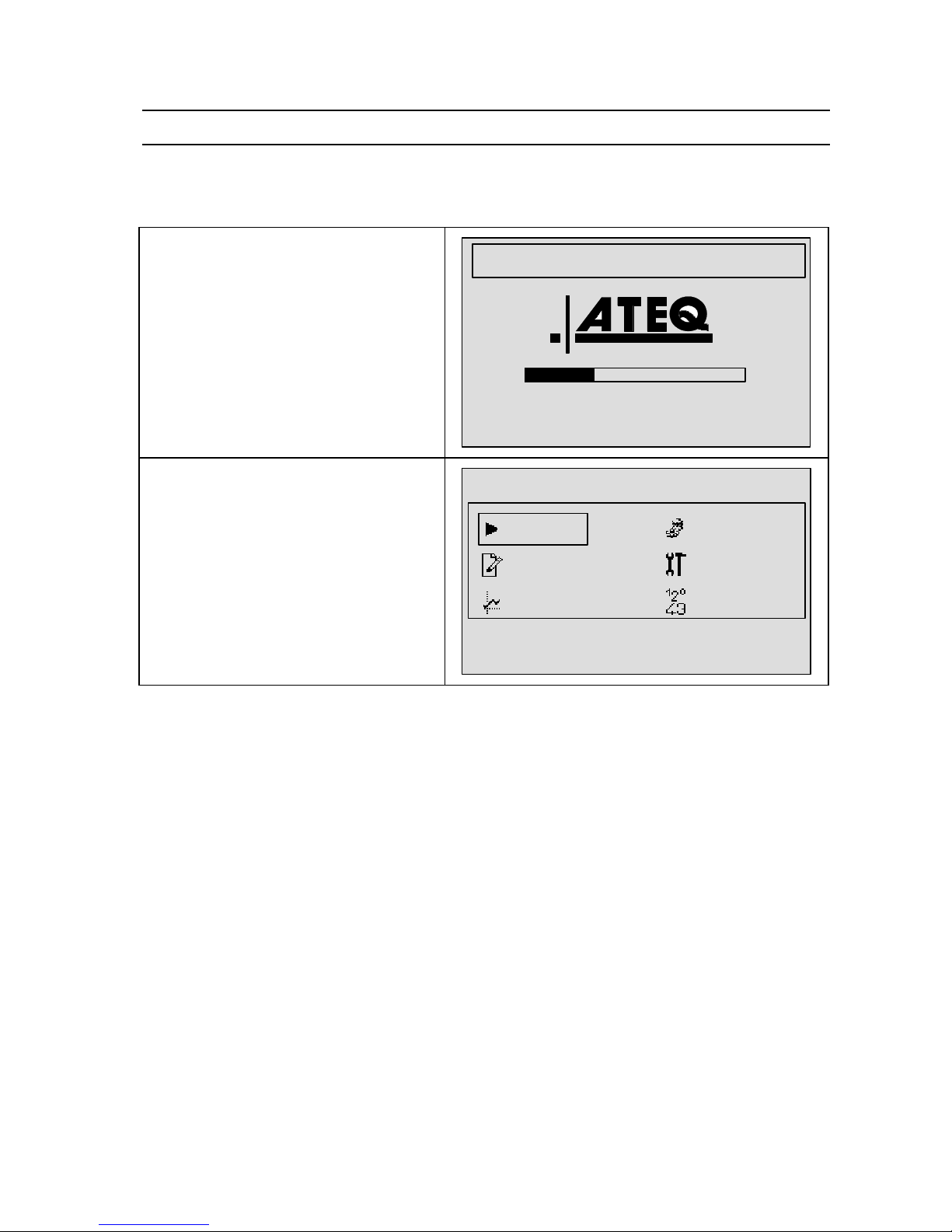
1. POWERING-UP THE INSTRUMENT
Connect the network power supply.
When it is powered, the instrument
initiates.
The movement of the bar graph
indicates the level of completion of
the start-up.
C 540 VX.XXi
STARTUP
Then displays the main menu, the
instrument is ready.
MAIN MENU
RUN CONFIG
PARAMETERS SERVICE
DISPLAY RESULTS
10:57:22 18/06/2002
Page 46
Chapter 3 – Start-up and settings
UM-18400E-U ATEQ F580 User manual Page 36/168
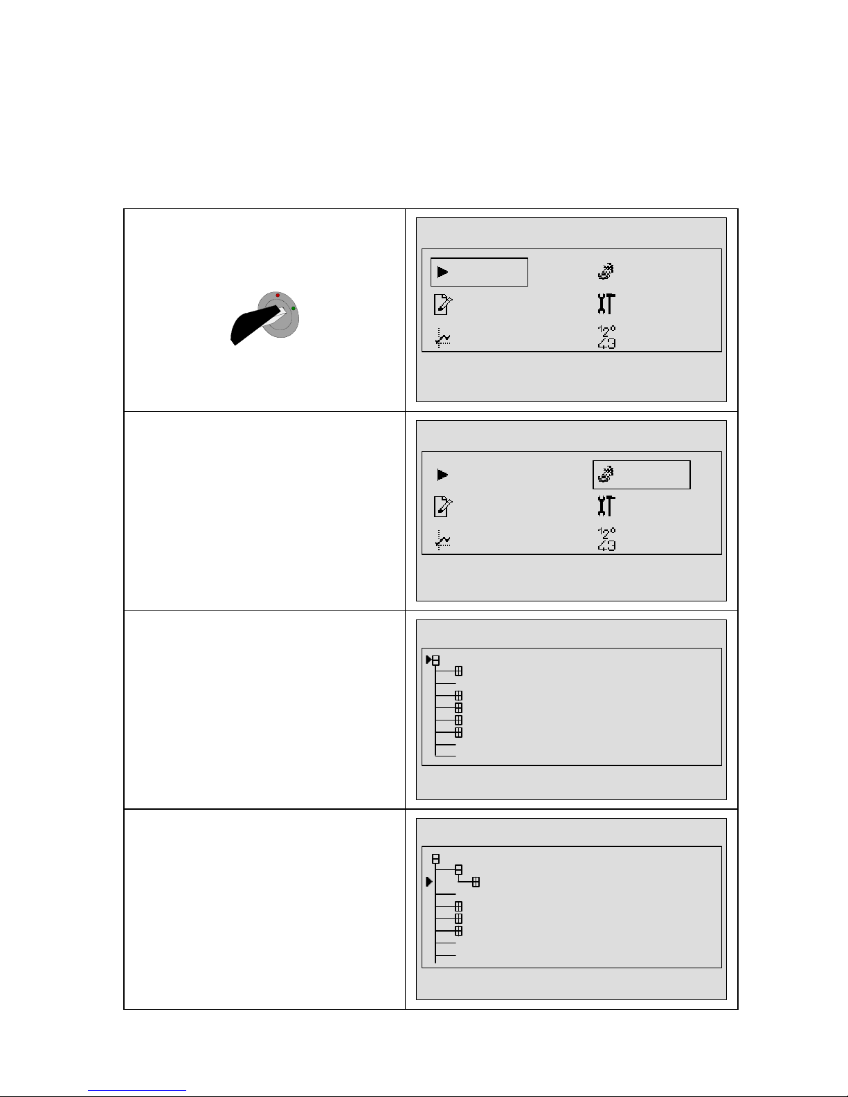
2. START-UP OF THE NETWORK
At the start-up of the network, it is necessary to identify the measurement units by giving
an address to each unit in the order required.
To number the units in the network, use the following procedure:
Turn the key to the ACCESS position.
MAIN MENU
RUN CONFIG
PARAMETERS SERVICE
DISPLAY RESULTS
10:57:22 18/06/2002
Then, with the navigation arrows,
select the "CONFIG" menu.
MAIN MENU
RUN CONFIG
PARAMETERS SERVICE
DISPLAY RESULTS
10:57:22 18/06/2002
Press on the ENTER button to enter
the configuration menu.
CONFIG
CENTRAL
NETWORK
LANGUAGE : ENGLISH
PRINTER
HOUR
BACKLIGHT
HEAD NAME
HEAD 01 : F5 :
HEAD 02 : F5 :
10:59:32 18/06/2002
Use the navigation keys to move the
cursor till it is in front of the
"INSTALLATION" menu then confirm
with ENTER.
CONFIG
CENTRAL
NETWORK
INSTALL
LANGUAGE : ENGLISH
PRINTER
HOUR
BACKLIGHT
HEAD NAME
HEAD 01 : F5 :
10:5
9:3218/06/2002
Page 47
Chapter 3 – Start-up and settings
UM-18400E-U ATEQ F580 User manual Page 37/168
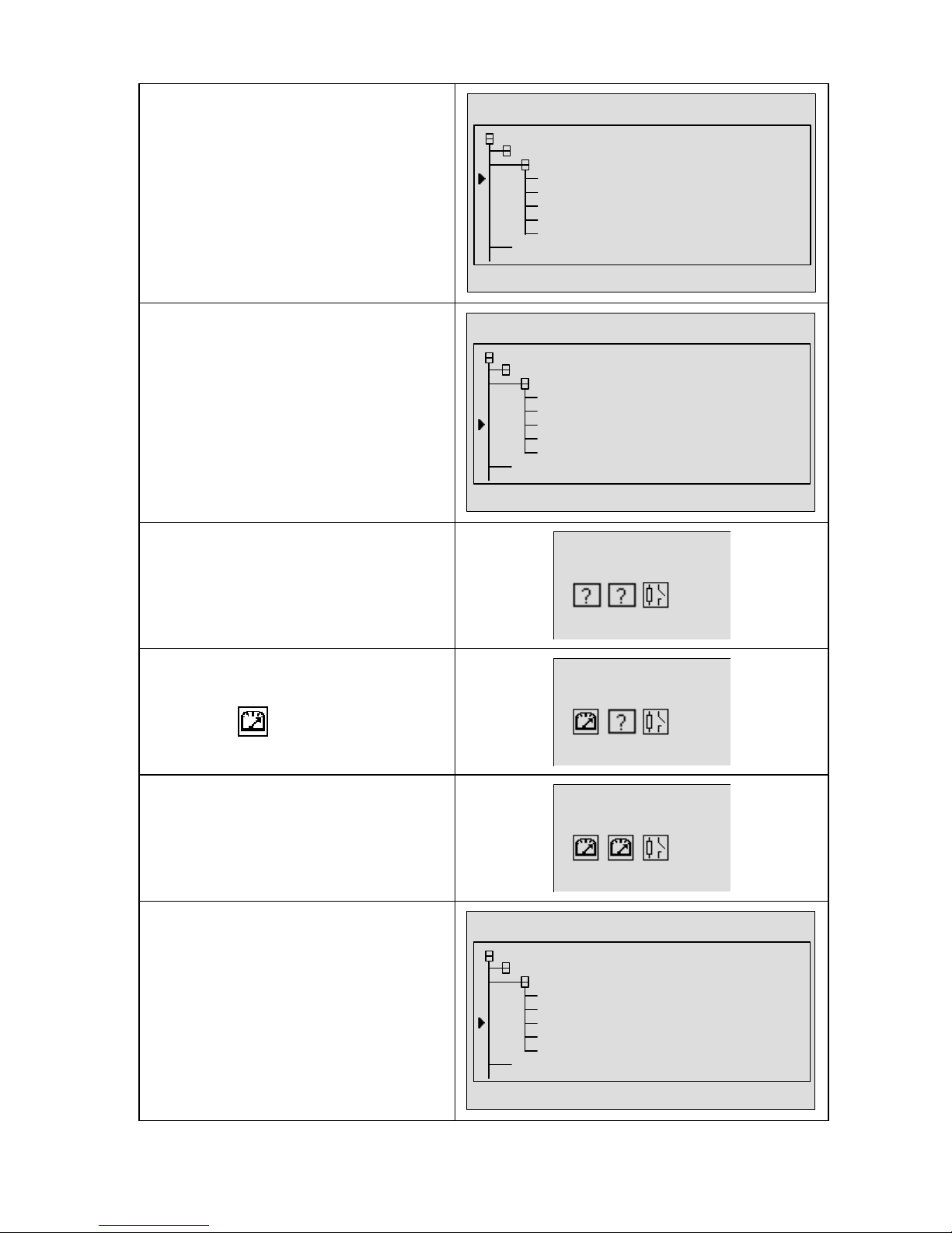
In the "Head (measurement unit)"
menu it is necessary to indicate the
quantity of measurement units which
are installed in the network.
In the "I/O Module" parameter it is
necessary to indicate the quantity of
input/output modules which are
installed in the network.
CONFIG
CENTRAL
NETWORK
INSTALL
HEAD : 02
I/O MODULES : 01
IDENTIFICATION
I/O MODE : EXTENDED
I/O DISTRIBUTION
LANGUAGE : ENGLISH
11:02:59 18/06/2002
By using the navigation keys, bring the
cursor in front of the
"IDENTIFICATION" menu and confirm.
CONFIG
CENTRAL
NETWORK
INSTALL
HEAD : 02
I/O MODULES : 01
IDENTIFICATION
I/O MODE : EXTENDED
I/O DISTRIBUTION
LANGUAGE : ENGLISH
11:06:45 18/06/2002
Each measurement unit (head) awaits
the validation of the numbering order.
Each instrument head must be
activated in the required order by using
the button on its back-panel.
IDENTIF
H01 H02 H03
??? ??? INT
The internal relay board is detected
and automatically validated; the
information appears on the screen
with the type of unit.
IDENTIF
H01 H02 H03
F5 ??? INT
Once all the measurement units are
identified, press on the ENTER key to
validate the installation.
IDENTIF
H01 H02 H03
F5 F5 INT
Once the measurement units are
validated, the instrument returns to the
"CONFIGURATION" menu. Return to
the main menu to carry out test cycles.
CONFIG
CENTRAL
NETWORK
INSTALL
HEAD : 02
I/O MODULES : 01
IDENTIFICATION
I/O MODE : EXTENDED
I/O DISTRIBUTION
LANGUAGE : ENGLISH
11:08:13 18/06/2002
Page 48
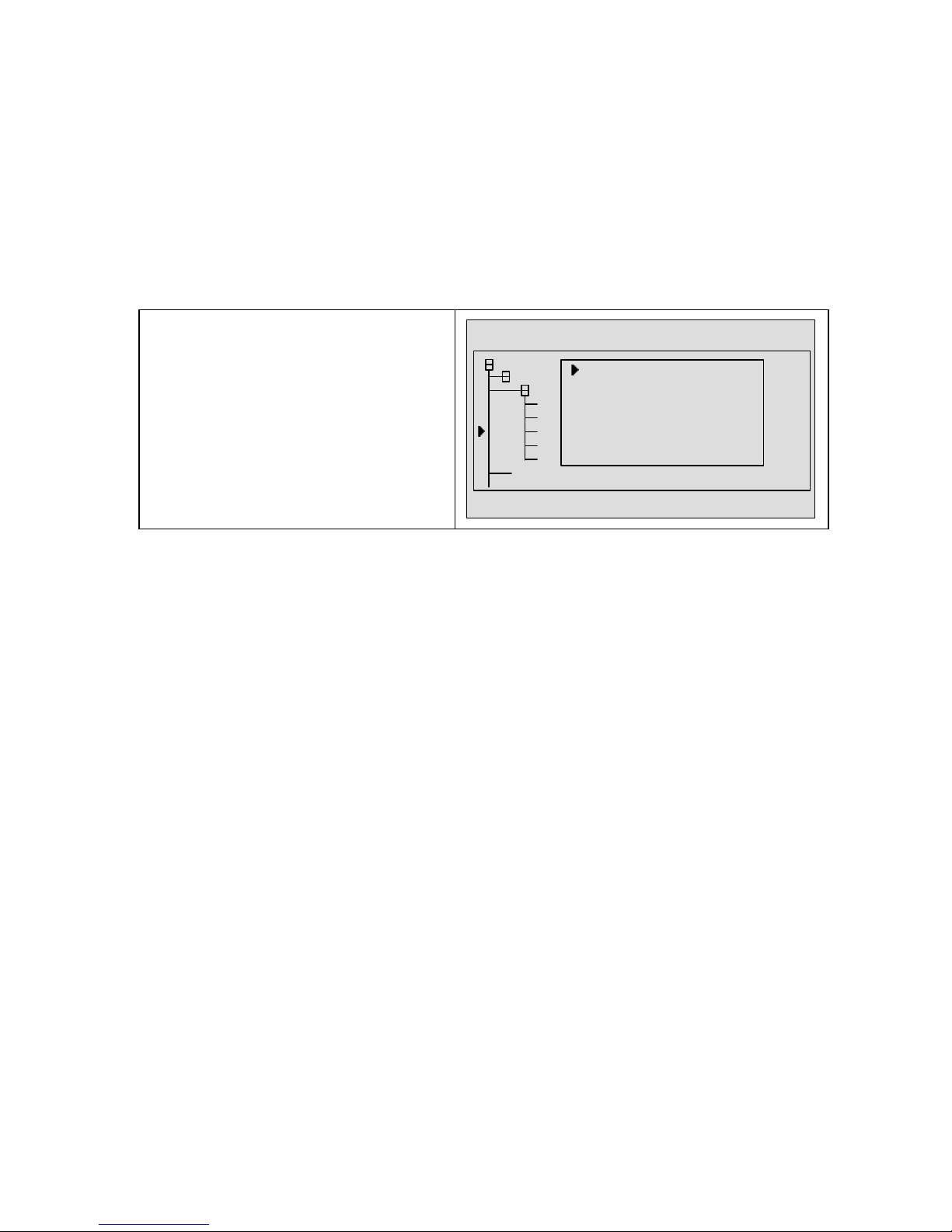
Chapter 3 – Start-up and settings
UM-18400E-U ATEQ F580 User manual Page 38/168
3. ALLOCATION OF THE OUTPUTS
The inputs / outputs can be set according to three different configurations, extended
mode, standard mode or compact mode. For the configuration of the outputs, refer to
chapter 1 paragraph 4.3.8 "J7 outputs connector" and paragraph 4.3.10 "J8 inputs
connector".
3.1. OUTPUTS ALLOCATION MODE
Choice of the outputs mode: place the
cursor in front of "I/O MODE" then
confirm, a window appears, choose
between the three modes and confirm.
CONFIG
CENTRAL
NETWORK
INSTALL
HEAD : 01
I/O MODULES : 01
I/O MODE : ETENDU
I/O DISTRIBUTION
IDENTIFICATION
LANGUAGE : ENGLISH
11:08:13 18/06/2002
EXTENDED
STANDARD
COMPACT
Note: the "Extended", "Standard" and "Compact" modes also concern the J8 inputs
connector. The measurement unit and number selection modes are different depending
on the chosen mode. Refer to chapter 1, paragraph 4.3.10 "J8 inputs connector".
Page 49
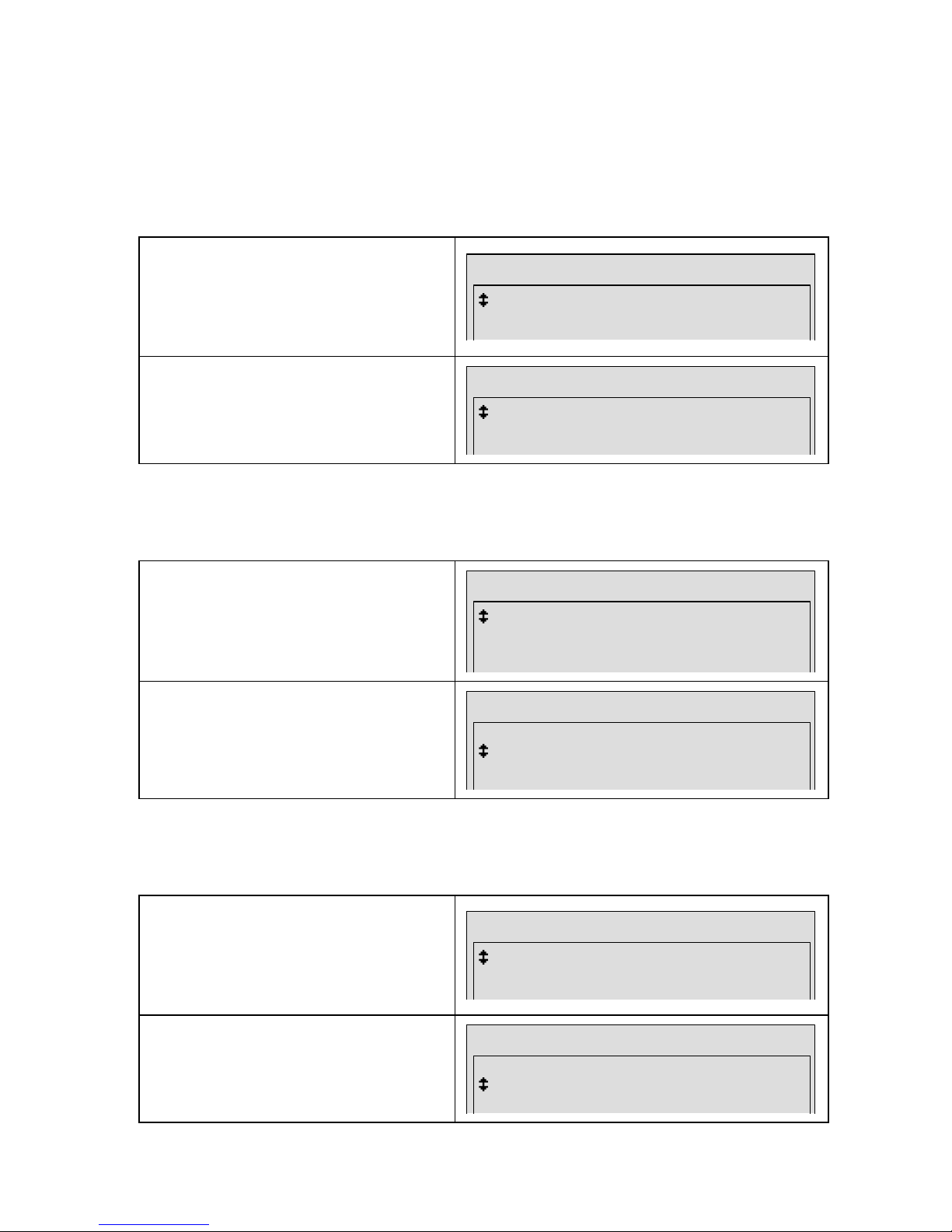
Chapter 3 – Start-up and settings
UM-18400E-U ATEQ F580 User manual Page 39/168
3.2. ALLOCATION OF THE MODULES
3.2.1. "Extended" mode
The extended mode configuration function enables modifications to be made allowing
the transfer of a measurement unit from one I/O module to another. Example with two
I/O modules and two measurement units (heads):
Confirm the "I/O DISTRIBUTION"
function. A list of measurement units
(heads) and their allocation to the
modules appears, confirm, the icon
changes into an “up/down arrow”.
CONFIG
MODULE 1 : HEAD 01
MODULE 2 : HEAD 02
Using the up and down keys, choose
the affectation of the unit on the
module required, confirm when the
selection is finished.
CONFIG
MODULE 1 : HEAD 02
MODULE 2 : HEAD 01
3.2.2. "Standard" mode
In standard mode configuration, this function enables the modification of the allocation
of a measurement unit on a block of an I/O module to transfer it to another.
Confirm the "I/O DISTRIBUTION"
function. A list of measurement units
(heads) and their allocation to the
modules appears, confirm, the icon
changes into an “up/down arrow”.
CONFIG
MODULE 1 BLOCK 1 : HEAD 01
MODULE 1 BLOCK 2 : HEAD 02
MODULE 1 BLOCK 3 : HEAD 03
Using the up and down keys, choose
the affectation of the unit on the
module required, confirm when the
selection is made.
CONFIG
MODULE 1 BLOCK 1 : HEAD 02
MODULE 1 BLOCK 2 : HEAD 01
MODULE 1 BLOCK 3 : HEAD 03
3.2.3. "Compact" mode
In compact mode configuration, this function enables the modification of the allocation
of a measurement unit on a block of an I/O module to transfer it to another.
Confirm the "I/O DISTRIBUTION"
function. A list of measurement units
(heads) and their allocation to the
modules appears, confirm, the icon
changes into an “up/down arrow”.
CONFIG
MODULE 1 OUTPUTS 1 : HEAD 01
MODULE 1 OUTPUTS 2 : HEAD 02
MODULE 1 OUTPUTS 3 : HEAD 03
Using the up and down keys, choose
the affectation of the unit on the
module required, confirm when the
selection is made.
CONFIG
MODULE 1 OUTPUTS 1 : HEAD 02
MODULE 1 OUTPUTS 2 : HEAD 01
MODULE 1 OUTPUTS 3 : HEAD 03
Page 50
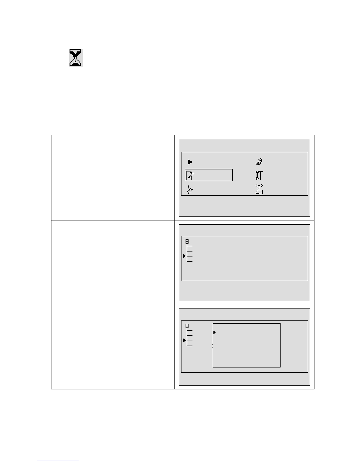
Chapter 3 – Start-up and settings
UM-18400E-U ATEQ F580 User manual Page 40/168
4. MANAGEMENT OF THE MEASUREMENT UNITS
The icon is displayed after confirmations. It indicates that the central module
communicates with the instruments in the network.
4.1. MEASUREMENT UNIT (HEAD) CONFIGURATION
The setting of parameters for a measurement unit on the keyboard of the C540 central
is done identically to the setting of the parameters on the front panel of the
measurement unit itself, after it has been selected. Example for the setting of a
measurement unit’s parameters:
From the main menu, select the
"PARAMETERS" menu and confirm
with the "ENTER" key.
MAIN MENU
RUN CONFIG
PARAMETERS SERVICE
DISPLAY RESULTS
10:48:1324/07/2002
By using the cursor, select the
measurement unit in which the
parameters are going to be modified
and confirm with the "ENTER" key.
PARAMETERS
CENTRAL
COPY : HEAD 00 : ---
PASTE : HEAD 00 : ---
HEAD 01 :F5 :
HEAD 02 :F5 :
10:49:3224/07/2002
The test programs of the measurement
unit are displayed, next, select the
program to be modified and confirm
with the "ENTER" key.
PARAMETERS
CENTRAL
COPY : HEAD 00 : ---
PASTE : HEAD 00 : ---
HEAD 01 :F5 :
HEAD 02 :F5 :
11:03:2524/07
/2002
Pr:01 LEAK TEST
Pr:02 LEAK TEST
Pr:03 BLOCKAGE
Pr:04 D MODE
Pr:05 OPERATOR
Pr:06 --------- Pr:07 ----------
Pr:08
----------
Page 51
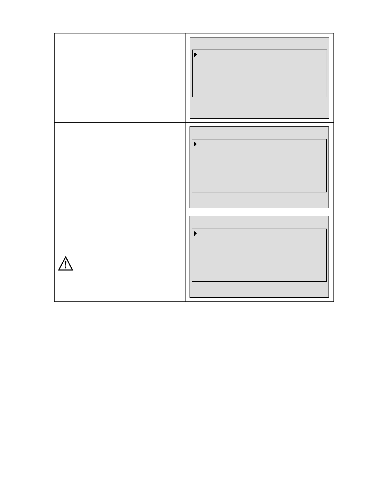
Chapter 3 – Start-up and settings
UM-18400E-U ATEQ F580 User manual Page 41/168
Next, access the parameters, the
functions, or carry out a copy-paste of
the parameters from one program to
another.
PARAMETERS
PARAMETERS
FUNCTIONS
Copy-Paste
11:10:0124/07
/2002
For the programming of the test
parameters, refer to the measurement
unit user manual.
To the right is an example of a
parameters window of a leak detection
unit.
PARAMETERS
TYPE : LEAK TEST
COUPLING A : 00.0 s
FILL : 01.0 s
STABILISATION : 00.5 s
TEST : 01.0 s
DUMP : 00.5 s
PRESSURE UNIT : bar
Max. FILL : 10.0 bar
Min. FILL : 0.000 bar
15:28:34 20/08/2002
To the right is an example of a functions
window of a leak detection
measurement unit.
The functions must be activated in
the "CONFIGURATION" menu to
appear in the "FUNCTIONS" menu.
PARAMETERS
NAME : CYLINDER HEAD
CYCLING : NO
TRANSIENT ABSORB. 0 : NO
TRANSIENT ABSORB. 1 : NO
TRANSIENT ABSORB. 2 : NO
PRE-FILL : NO
FILL MODE : NO
VALVES CODES : NO
END CYCLE : NO
15:39:59 20/08/2002
Page 52
Chapter 3 – Start-up and settings
UM-18400E-U ATEQ F580 User manual Page 42/168
4.2. CREATION OF A TEST PROGRAM
To create a test program for a measurement unit on the C540 central unit keyboard
follow the procedure below.
Setting the parameters for a measurement unit:
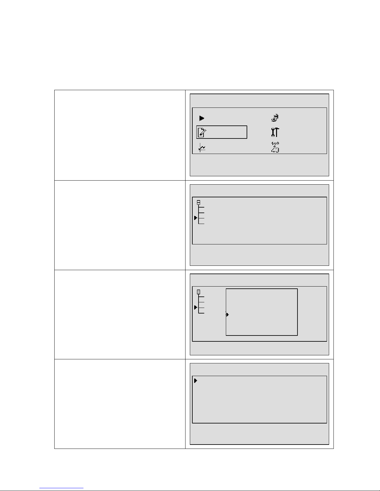
From the main menu, select the
"PARAMETERS" menu and confirm
with the "ENTER" key.
MAIN MENU
RUN CONFIG
PARAMETERS SERVICE
DISPLAY RESULTS
10:48:2324/07
/2002
Using the cursor, select the
measurement unit in which the
parameters will be modified and confirm
with the "ENTER" key.
PARAMETERS
CENTRAL
COPY : HEAD 00 : ---
PASTE : HEAD 00 : ---
HEAD 01 :F5 :
HEAD 02 :F5 :
10:49:3224/07/2002
The measurement unit test programs
which have already been created are
displayed. Next, select an empty
program to be created (usually "--------")
and confirm with the "ENTER" key.
PARAMETERS
CENTRAL
COPY : HEAD 00 : ---
PASTE : HEAD 00 : ---
HEAD 01 :F5 :
HEAD 02 :F5 :
11:03:2524/07
/2002
Pr:01 LEAK TEST
Pr:02 LEAK TEST
Pr:03 LEAK TEST
Pr:04 OPERATOR
Pr:05 --------- Pr:06 --------- Pr:07 ----------
Pr:08
----------
Next, access the parameters, the
functions or carry out a copy-paste
operation to another program.
PARAMETERS
PARAMETERS
FUNCTIONS
Copy-Paste
11:10:0124/07
/2002
Page 53
Chapter 3 – Start-up and settings
UM-18400E-U ATEQ F580 User manual Page 43/168
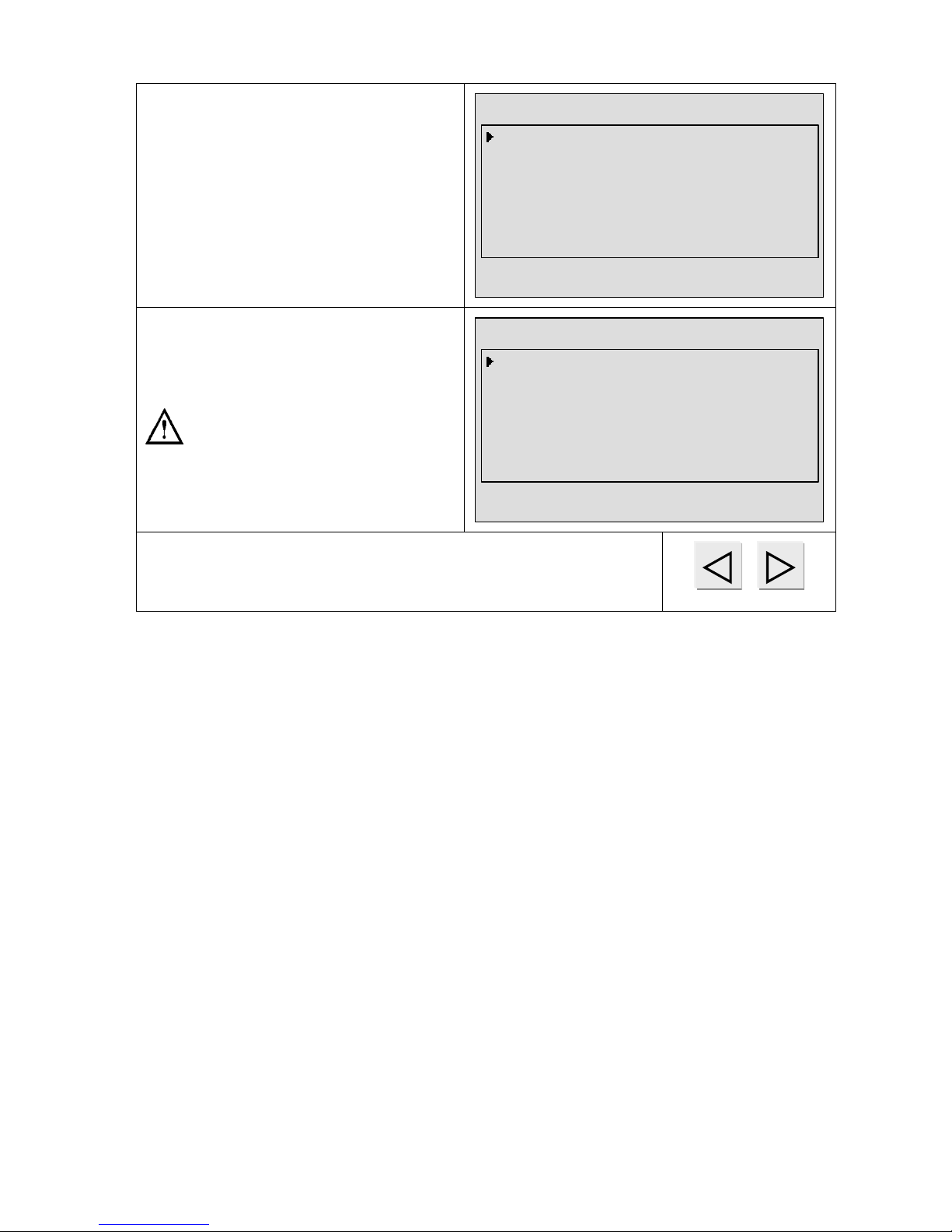
For the programming of the test
parameters please refer to the manual
concerning the measurement unit.
To the right is an example of a leak
detection unit parameters window.
PARAMETERS
TYPE : LEAK TEST
COUPLING A : 00.0 s
FILL : 01.0 s
STABILISATION : 00.5 s
TEST : 01.0 s
DUMP : 00.5 s
PRESSURE UNIT : bar
Max. FILL : 10.0 bar
Min. FILL : 0.000 bar
15:28:34 20/08/2002
To the right is an example of a leak
detection unit functions window.
The functions must be activated in
the "CONFIGURATION" menu to
appear in the "FUNCTION" menu.
PARAMETERS
NOM : CYLINDER HEAD
CYCLING : NO
TRANSIENT ABSORB. 0 : NO
TRANSIENT ABSORB. 1 : NO
TRANSIENT ABSORB. 2 : NO
PRE-FILL : NO
FILL MODE : NO
VALVES CODES : NO
END CYCLE : NO
15:39:59 20/08/2002
Note: when a parameter is modified, it is possible to move the
comer to unit, ten, hundred, etc. by using the left and right
arrows.
Page 54
Chapter 3 – Start-up and settings
UM-18400E-U ATEQ F580 User manual Page 44/168
4.3. TEST TYPE SELECTION
Four types of test are available.
The PARAMETERS menu
gives access to four possible
types of test: leak test (LEAK
TEST), pressure test
(BLOCKAGE), desensitised
mode test (D. MODE) and an
operator test (OPERATOR);
see the following paragraph
for explanations.
Put the cursor in front of the
required test type and confirm
with the ENTER key.
PARAMETERS
TYPE
15:40:2520/08
/2002
--------- LEAK TEST
BLOCKAGE
D MODE
OPERATOR
4.3.1. Leak test
The leak test is most suitable for measuring small leaks (pressure drop). The following
formula is used to convert a leak expressed in units of flow to a drop in pressure:
)(cm V x 0,0006
/min)(cm F
(Pa/s) P
3
3
=∆
F(cm3/min) = Leak flow
0.0006 = constant
V (cm3) = volume of the test part
∆P (Pa/s) = pressure drop
Example:
Part which has dP/dt = 50 Pa/s Part which has dP/dt = 1 Pa/s
Test
1 s
2 s
3 s
.
.
n s
Pa/s
50
50
50
.
.
50
Pa
50
100
150
.
.
nx50
Test
1 s
2 s
3 s
.
.
n s
Pa/s
1
1
1
.
.
1
Pa
1
2
3
.
.
n
The choice of working in Pa or in Pa/s depends on the application.
In all events, it must not be forgotten that the full scale of the sensor in Pa or Pa/s is
limited to 50 or 500 Pa depending on the instrument configuration.
Page 55
Chapter 3 – Start-up and settings
UM-18400E-U ATEQ F580 User manual Page 45/168
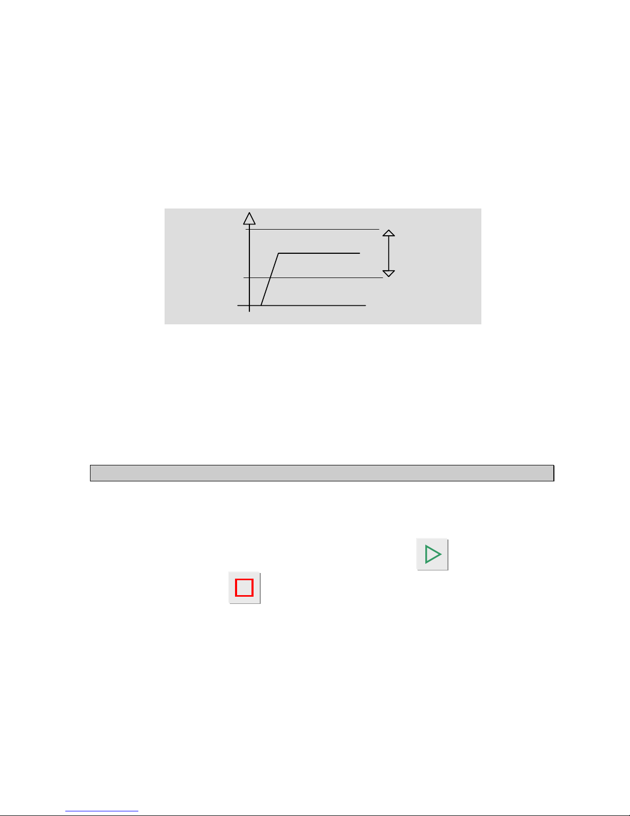
4.3.2. Blockage test mode
The blockage mode is used for rough measurement of a flow, based on measurement
of back pressure. The standard pressure limits are used to classify the result as good or
bad. The cycle only contains the fill phase and the reading is carried out during this
phase.
If the pressure measured is below the minimum limit, then the flow is too large.
If the pressure measured is in excess of the maximum limit, then the flow is too small.
LOW THRESHOLD
GOOD PARTS
HIGH THRESHOLD
4.3.3. Desensitised mode test
This mode is used for the measurement of large leaks, when the reject level required is
above 500 Pa.
The unit used during the reading of the pressure drop in desensitised mode is the unit
which is used for the display of the test pressure (identical resolution). The limits will
also be indicated in this unit.
)Calibration may not be used in this mode.
4.3.4. Operator mode test
This type of test means that the operator can carry out operations on the part whilst
under test, then to confirm these operation using a "START" key if the operator
test is good, or "RESET"
key if the test is fail.
Page 56
Chapter 3 – Start-up and settings
UM-18400E-U ATEQ F580 User manual Page 46/168
4.4. PARAMETER SETTINGS
Once the test type is chosen, the test cycle parameters must be set.
The procedure to follow for setting the test parameters is identical in each case.
Example: Coupling time A.
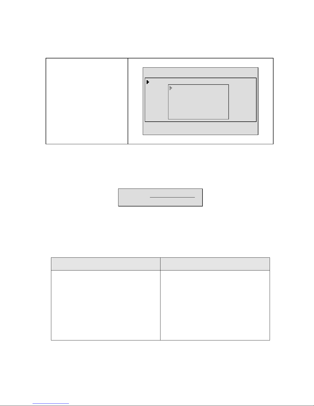
First, place the cursor in front of the
chosen parameter with the navigation
keys (here, coupling time A).
PARAMETERS
TYPE : LEAK TEST
COUPLING A : 00.0 s
FILL : 01.0 s
STABILISATION : 00.5 s
TEST : 01.0 s
DUMP : 00.5 s
PRESSURE UNIT : bar
Max. FILL : 10.0 bar
Min. FILL : 0.000 bar
15:48:14 20/08/2002
Next, validate with the ENTER key. The
cursor moves from the left side to the
right side of the display.
PARAMETERS
TYPE : LEAK TEST
COUPLING A : 00.0 s
FILL : 01.0 s
STABILISATION : 00.5 s
TEST : 01.0 s
DUMP : 00.5 s
PRESSURE UNIT : bar
Max. FILL : 10.0 bar
Min. FILL : 0.000 bar
15:48:44 20/08/2002
Modify the value with the up and down
navigation keys.
PARAMETERS
TYPE : LEAK TEST
COUPLING A : 02.0 s
FILL : 01.0 s
STABILISATION : 00.5 s
TEST : 01.0 s
DUMP : 00.5 s
PRESSURE UNIT : bar
Max. FILL : 10.0 bar
Min. FILL : 0.000 bar
15:49:03 20/08/2002
Once the value is modified, validate
with the ENTER key.
PARAMETERS
TYPE : LEAK TEST
COUPLING A : 02.0 s
FILL : 01.0 s
STABILISATION : 00.5 s
TEST : 01.0 s
DUMP : 00.5 s
PRESSURE UNIT : bar
Max. FILL : 10.0 bar
Min. FILL : 0.000 bar
15:49:53 20/08/2002
Page 57
Chapter 3 – Start-up and settings
UM-18400E-U ATEQ F580 User manual Page 47/168
To move on to the following parameter,
use the up and down navigation arrows.
PARAMETERS
TYPE : LEAK TEST
COUPLING A : 02.0 s
FILL : 01.0 s
STABILISATION : 00.5 s
TEST : 01.0 s
DUMP : 00.5 s
PRESSURE UNIT : bar
Max. FILL : 10.0 bar
Min. FILL : 0.000 bar
15:50:15 20/08/2002
To exit the menu, use the
C
key.
PARAMETERS
PARAMETERS
FUNCTIONS
Copy-Paste
11:51:1020/08/2002
4.4.1. Coupling time
Coupling times A and B are start of cycle parameters. If there is no automatic
connector, Coupling time A is part of the cycle.
If an instrument is fitted with an automatic connector, Coupling time A delays the
pressurisation of the test part by allowing the activation of a first cycle connector at the
test start. Coupling time B allows the activation of a second automatic connector. These
Coupling times ensure better stabilisation of the seals placed on the test part.
)Set this parameter using the method described in § 4.4.
4.4.2. Fill time
This is the time allowed for the pressurisation of the part to be tested. It must not be too
long (waste of time) or too short (the pressure in the component is at risk of not being
sufficient due to drops in pressure caused by temperature changes).
To determine the appropriate fill time, it is necessary to set the Fill Time in order to
make it Too Long (TTLR), then to shorten it until a drop in pressure occurs due to
thermal effects.
Determine the TTLR by using the following formula:
4
mbar in pressure test x cm in volumeTTLR3=
9 Carry out a cycle. When the instrument switches to the stabilisation period, the
pressure must remain stable.
Page 58

Chapter 3 – Start-up and settings
UM-18400E-U ATEQ F580 User manual Page 48/168
9 A pressure drop (since there will be no fall in pressure due to thermal effects)
signifies the presence of a large leak; check the test part and the pneumatic
assembly components, then start again.
9 If the pressure remains stable, the part does not contain a large leak and the fill time
is too long. Shorten it progressively by carrying out cycles until a drop in pressure is
noticeable.
9 As soon as a fall in pressure due to thermal effects appears, the fill time has become
too short. Increase it slightly.
)Set this parameter using the method described in § 4.4.
4.4.3. Stabilisation time
This time is used to equalise the pressure between the TEST and REFERENCE
components.
Two phenomena may interfere with the equalisation:
9 Different pipes
The first phenomenon that may appear is a pressure variation between the
components, caused by thermal effects. In actual fact, if the connection pipes are
different (length or diameter) the target pressure will be reached faster in the part with
the most favourable set-up. If the differential sensor switches to measurement too early,
the instrument will indicate the presence of a large leak.
9 Different volumes
The second phenomenon which may appear is a pressure difference between the
components due to their differing volumes.
In effect, if, at the end of the fill time, the volumes are different, the component with the
smaller volume will stabilise faster. If the differential sensor switches to measurement
too early, the instrument will indicate a large leak.
9 To determine the correct stabilisation time, it is necessary to set a long time so that
the reading at the end of the test time is equal to zero.
9 Set the stabilisation time to four times the length of the fill time.
9 Carry out a cycle. When the instrument switches to the test period, the pressure
must remain at zero.
9 If there is a drop in pressure, there is a small leak present. Check the test part and
the pneumatic connections, then start again.
9 If the pressure is stable, the part does not contain a small leak and the stabilisation
time is therefore too long. Progressively shorten and carry out cycles (wait one
minute between each cycle) until you see the appearance of a drop in pressure. This
indicates that the stabilisation time has become too short. Increase it slightly.
)Set this parameter using the method described in § 4.4.
Page 59
Chapter 3 – Start-up and settings
UM-18400E-U ATEQ F580 User manual Page 49/168
4.4.4. Test time
The test time depends on the programmed reject level and operation mode
In the dP/dt (Pa/s) mode, the variation in measured pressure is due to the drift in the
pressure drop. .
In the dP (Pa) mode, the pressure variation measured is the total of the pressure drop
over the whole test time. This mode is more unstable, but is more sensitive. The
instrument totals all the variations occurring due to variations in volume or temperature
over the whole test time.
)Set this parameter using the method described in § 4.4.
4.4.5. Dump time
The instrument will as default propose a dump time of zero. This must be set by
carrying out several tests.
)Set this parameter using the method described in § 4.4.
4.4.6. Pressure units
The different units are bar, mbar, PSI, Pa, kPa, MPa.
) Set this parameter using the method described in § 4.4.
4.4.7. Maximum fill
This function is used to set a maximum limit for the fill pressure. A warning is triggered if
this limit is exceeded.
When test time is infinite, the maximum fill pressure monitoring is
inoperative. Care should therefore be taken to avoid excess pressure being
applied to the part during the test.
) Set this parameter using the method described in § 4.4.
4.4.8. Minimum fill
This function is used to set a minimum limit for the fill pressure. A warning is triggered if
this limit is not reached.
) Set this parameter using the method described in § 4.4.
4.4.9. Filling instruction
This function gives the user the option not to have to adjust the test pressure manually
using the regulator. Simply set the test pressure value and the instrument adjusts it
automatically. This function can be used with a mechanical regulator (regulator with an
adjustable knob) or an electronic regulator (no adjustment).
Page 60

Chapter 3 – Start-up and settings
UM-18400E-U ATEQ F580 User manual Page 50/168
4.4.9. 1) Setting
Simply set the regulator to a pressure which is higher than test pressure. When target
fill pressure is reached, the air supply is automatically cut off and the instrument moves
into stabilisation mode.
4.4.10. Reject unit
Pa, Pa/s, (High Resolution) Pa, (High Resolution) Pa/s, Cal-Pa, Cal-Pa/s, cm3/min,
cm3/s, cm3/h, mm3/s.
If a unit of flow is selected, two parameters will be added to the program:
9 the choice of the flow calculation basis, in Pa or Pa/s
9 the volume of the test part (+pipes).
There is a special “calc volume” cycle which enables the volume of a part to be
estimated, and there is a special "Cal learn" cycle to determine a basic unit of flow. (see
chapter 4 § 3.3.5 "volume calculation" and § 3.3.6 "manual calibration").
Note: high resolution enables an extra figure to be displayed (i.e. 1/10 Pa)
) Set this parameter using the method described in § 4.4.
4.4.11. Test reject
This function is used to set a limit level below which the part is considered to be bad.
) Set this parameter using the method described in § 4.4.
4.4.12. Reference reject
This function is used to set a limit level below which the reference part is considered to
be bad.
Note: when the reference reject value is zero, the program allows for the absolute value
of the test reject (for example: if the test reject is 10 Pa, and the reference reject value
equal to zero, the program takes the reference reject to be – 10 Pa).
) Set this parameter using the method described in § 4.4.
4.4.13. Functions
The FUNCTION menu gives access to additional parameters which must first be
activated in the CONFIGURATION menu and then the EXTENDED MENU.
If no additional parameters are confirmed in the EXTENDED MENUS, the FUNCTION
menu will be empty when selected.
To activate these parameters, refer to chapter 4 § 2.2.
Page 61
Chapter 3 – Start-up and settings
UM-18400E-U ATEQ F580 User manual Page 51/168
5. DUPLICATION OF A TEST PROGRAM
To modify the parameters, turn the key
to the ACCES position.
In the PARAMETERS menu, place the
cursor in front of the Copy Paste
function.
Confirm this function again by pressing
on the ENTER key.
PARAMETERS
PARAMETERS
FUNCTIONS
Copy-Paste
16:53:1320/08/2002
Confirm the "COPY" function to select
the program which will be copied.
PARAMETERS
COPY :
PASTE :
16:54:0420/08
/2002
Pr:01 LEAK TEST
Pr:02 LEAK TEST
Pr:03 LEAK TEST
Then, in the "PASTE" function select
the program number in which the first
program selected will be copied.
Confirm with the ENTER key.
The program is instantly copied.
PARAMETERS
COPY :
PASTE :
16:54:5620/08
/2002
Pr:01 LEAK TEST
Pr:02 LEAK TEST
Pr:03 LEAK TEST
Pr:04 ----------
Pr:05 ----------
Pr:0
6
-
---------
Press several times on the C key to
return to the main menu.
C
Page 62
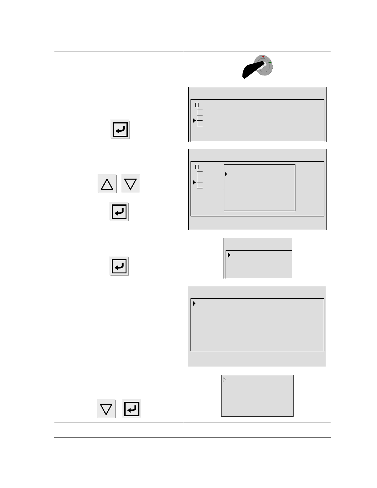
Chapter 3 – Start-up and settings
UM-18400E-U ATEQ F580 User manual Page 52/168
6. DELETING A TEST PROGRAM
To modify the parameters, turn the key
to the ACCES position.
In the "PARAMETERS" menu, select
the head in which the program is to be
deleted and confirm with the "ENTER"
key.
.
PARAMETERS
CENTRAL
COPY : HEAD 00 : ---
PASTE : HEAD 00 : ---
HEAD 01 :F5 :
HEAD 02 :F5 :
The test programs are displayed, next,
select the program to be deleted
and confirm with the "ENTER" key.
PARAMETERS
CENTRAL
COPY : HEAD 00 : ---
PASTE : HEAD 00 : ---
HEAD 01 :F5 :
HEAD 02 :F5 :
11:03:2524/07
/2002
Pr:01 LEAK TEST
Pr:02 LEAK TEST
Pr:03 LEAK TEST
Pr:04 OPERATOR
Pr:05 --------- Pr:06 --------- Pr:07 ----------
Pr:08
----------
Next, access the parameters and
confirm with the "ENTER" key.
P
ARAM
PARAMETERS
FUNCTIONS
Copy-Paste
The cursor being on front of the test
type, confirm with the "ENTER" key.
PARAMETERS
TYPE : LEAK TEST
COUPLING A : 02.0 s
FILL : 01.0 s
STABILISATION : 00.5 s
TEST : 01.0 s
DUMP : 00.5 s
PRESSURE UNIT : bar
Max. FILL : 10.0 bar
Min. FILL : 0.000 bar
15:50:15 20/08/2002
The list of the available test types is
displayed, select the "---------" line and
confirm with the ENTER key.
--------- LEAK TEST
BLOCKAGE
D MODE
OPERATOR
The program selected is deleted.
Page 63
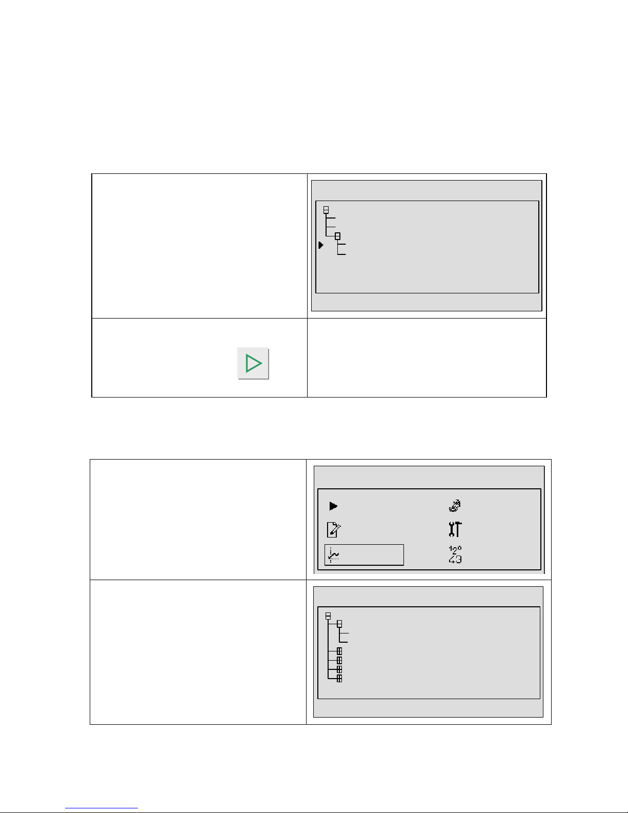
Chapter 3 – Start-up and settings
UM-18400E-U ATEQ F580 User manual Page 53/168
7. LAUNCHING A CYCLE
7.1. START KEY
It is possible to start a test cycle on one, several or all the measurement units (heads). It
is actually possible to allocate one or more units to the START key. For that, just select
the units which are required to start a cycle with "YES" in the "RUN/START KEY" menu.
In the "RUN" menu, select the "START
KEY" menu; confirm with a "YES" the
measurement units for which we want to
start a test program.
RUN
CENTRAL
HEAD 01 : F5 :
HEAD 02 : F5 :
START KEY
HEAD 01 : YES
HEAD 02 : YES
11:02:59
18/06/2002
Press on the START key to launch the
measurement cycle.
Depending on the display mode chosen, the
cycle stages and the results are presented
differently.
Refer to chapter 4, paragraph 1.4 "display
menu".
7.2. DISPLAY OF THE MEASUREMENTS
Before starting the measurements, select a display type:
To do this, in the main menu, select the
"DISPLAY MENU".
MAIN MENU
RUN CONFIG
PARAMETERS SERVICE
DISPLAY RESULTS
In the "DISPLAY MENU" select the
"STANDARD" menu, then validate with
a "YES".
Next, confirm with a "YES" the unit(s)
displayed on the screen.
DISPLAY
CENTRAL
STANDARD : YES
HEAD 1 : YES
HEAD 2 : YES
COMPACT : NO
RESULTS : NO
CURVE : YES
LED DISPLAY : NO
09:19:36 21/08/2002
Page 64
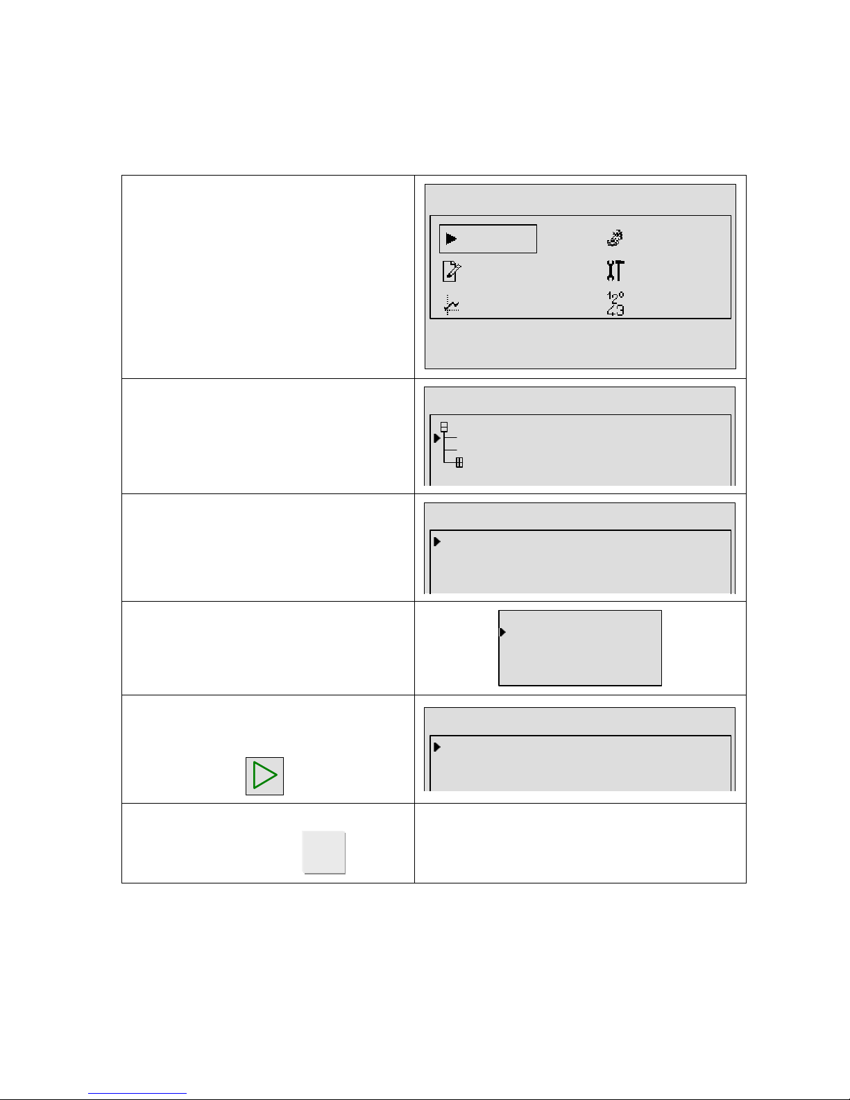
Chapter 3 – Start-up and settings
UM-18400E-U ATEQ F580 User manual Page 54/168
7.3. CHOICE OF THE MEASUREMENT UNIT PROGRAM
To choose the program to be carried out by a measurement unit (head), it is necessary
to previously select it, to do this, follow the procedure presented below:
Select the "RUN" menu and confirm
with the "ENTER" key.
MAIN MENU
RUN CONFIG
PARAMETERS SERVICE
DISPLAY RESULTS
16:45:32 11/07/2002
Select the unit in which the cycle
number choice must be made and
confirm.
RUN
CENTRAL
HEAD 1 : F5 :
HEAD 2 : F5 :
START KEY
Place the cursor in front of the "ACTIVE
PROG" menu and confirm.
RUN
RUN PROGRAMME : Pr01 LEAK TEST
SPECIAL CYCLE : Disabled
In the menu, select the program to be
activated (only programs created are
displayed), then confirm.
Pr:01 LEAK TEST
Pr:02 LEAK TEST
Pr:03 LEAK TEST
Pr:04 OPERATOR
The instrument confirms the program
number selected, it is now possible to
start the cycle (in this unit only) by using
the key.
RUN
RUN PROGRAMME : Pr02 LEAK TEST
SPECIAL CYCLE : Disabled
Return to the main menu by pressing
several times on the
C
key.
Note: it is possible to start all the measurement units at the same time by pressing on
the start key in a previous menu.
Page 65
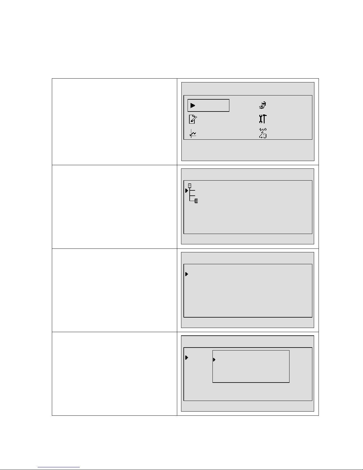
Chapter 3 – Start-up and settings
UM-18400E-U ATEQ F580 User manual Page 55/168
8. LAUNCH OF A SPECIAL CYCLE
To start a special cycle on a measurement unit follow the procedure below. Example for
the adjustment of a regulator:
Select the "RUN" menu and confirm
with the "ENTER" key.
MAIN MENU
RUN CONFIG
PARAMETERS SERVICE
DISPALY RESULTS
16:45:32 11/07/2002
Select the measurement unit (head)
with which the special cycle must be
started then confirm.
RUN
CENTRAL
HEAD 1 : F5 :
HEAD 2 : F5 :
START KEY
16:54:35 11/07/2002
Place the cursor in front of the
"SPECIAL CYCLE" menu and confirm.
RUN
RUN PROGRAMME : Pr01 LEAK TEST
SPECIAL CYCLE : Disabled
17:41:07 11/07/2002
All the special cycles available are
displayed, place the cursor in front of
the special cycle required (here,
"Regulator adjust. 1") and confirm.
RUN
RUN PROGRAMME : Pr01 LEAK TEST
SPECIAL CYCLE : Disabled
17:41:07 11/07/2002
Disabled
Regulator adjust 1
Regulator adjust 2
Infinite fill
Piezo auto zero
Page 66
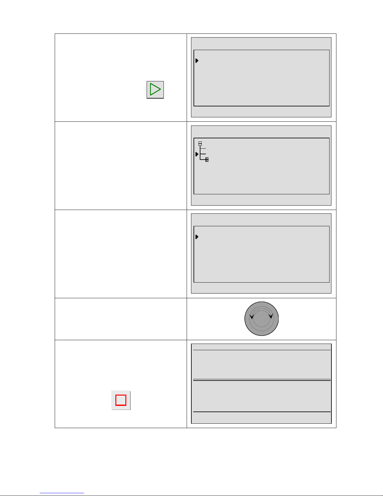
Chapter 3 – Start-up and settings
UM-18400E-U ATEQ F580 User manual Page 56/168
The instrument confirms the selection of
the special cycle "Regulator adjust. 1",
it is now possible to start the cycle (in
this unit only) by using the key.
RUN
RUN PROGRAMME : Pr01 LEAK TEST
SPECIAL CYCLE : Regulator 1
17:41:07 11/07/2002
It is possible to make several
measurement units carry out different
special cycles. To do so, just select the
units one after the other and confirm the
special cycles that are required on each
given unit.
RUN
CENTRAL
HEAD 1 : F5 :
HEAD 2 : F5 :
START KEY
16:41:57 11/07/2002
After having selected all the special
cycles, return to the main menu, then
launch all the special cycles at once.
RUN
RUN PROGRAMME : Pr01 LEAK TEST
SPECIAL CYCLE : Infinte Fill
17:42:18 11/07/2002
Adjust the pressure(s) with the regulator
handle(s).
_
+
Press on the RESET key to stop the
special cycle in progress. The
instrument(s) stop the cycle and
prepare for a new measurement cycle.
ATEQ C540
---- H01 ---RUN/Pr:001
PRESS = 1.50 bar
LEAK = 059 Pa
READY (OK)
---- H02 ---RUN/Pr:001
PRESS = 2.00 bar
LEAK = 008 Pa
READY (OK)
Page 67
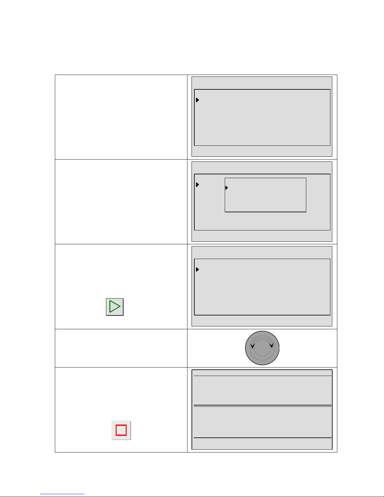
Chapter 3 – Start-up and settings
UM-18400E-U ATEQ F580 User manual Page 57/168
9. ADJUSTMENT OF THE TEST PRESSURE
9.1. MANUAL ADJUSTMENT WITH MECHANICAL REGULATOR
In the main menu, select the "RUN"
menu, next, place the cursor in front of
"SPECIAL CYCLE" and confirm.
RUN
RUN PROGRAMME : Pr01 LEAK TEST
SPECIAL CYCLE : Disabled
17:41:07 11/07/2002
Amongst the special cycles available
select the "Regulator 1 adjustment"
cycle and confirm.
RUN
RUN PROGRAMME : Pr01 LEAK TEST
SPECIAL CYCLE : Disabled
17:41:07 11/07/2002
Disabled
Regul. 1 adjustment
Regul. 2 adjustment
Infinite fill
Piezo auto zero
The instrument confirms the choice of
the special cycle "Regulator 1
adjustment", it is now possible to start
the cycle (in this instrument only) by
using the START
key.
RUN
RUN PROGRAMME : Pr01 LEAK TEST
SPECIAL CYCLE : Regulator 1
17:41:07 11/07/2002
Adjust the pressure(s) with the
handle(s) of the regulator(s).
_
+
Press on the RESET key to stop the
special cycle in progress. The
instrument stops its cycle and
configures itself for a new measurement
test.
ATEQ F580
---- H01 ---RUN/Pr:001
PRESS = 1.50 bar
READY
---- H02 ---RUN/Pr:001
PRESS = 2.00 bar
READY
Page 68
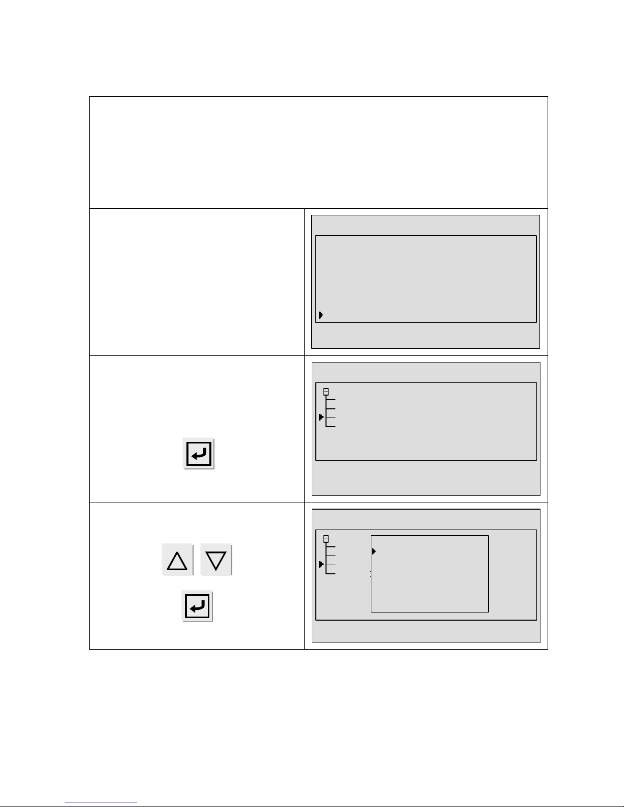
Chapter 3 – Start-up and settings
UM-18400E-U ATEQ F580 User manual Page 58/168
9.2. INSTRUCTION ADJUSTMENT WITH MECHANICAL REGULATOR
To access the filling instruction function, it must first be activated in the expanded
menus before the test program is created.
Refer to chapter 4 § 2.2.1 "EXTENDED MENUS"
and § 2.2.1.1) "Activation of additional functions".
Then refer to § 2.2.1.3) j) "Fill mode".
If the instrument is fitted with two regulators
also refer to § 2.2.1.3) l) "Fill regulator"
to identify which of the two regulators is the fill regulator.
Validate the special function in the
"EXTENDED MENUS" menu of the
heads configuration.
CONFIG
NAME : NO
CYCLING : NO
AUTO CONNECTOR : NO
ETAL CHECK : NO
TRANSIENT ABSORB. 0 : NO
TRANSIENT ABSORB. 1 : NO
TRANSIENT ABSORB. 2 : NO
P.FILL MODE : NO
FILL MODE : YES
10:48:26 24/07/2002
In the "PARAMETERS" menu, select
the head and validate with the "ENTER"
key
.
PARAMETERS
CENTRAL
COPY : HEAD 00 : ---
PASTE : HEAD 00 : ---
HEAD 01 :F5 :
HEAD 02 :F5 :
10:49:3224/07/2002
Select the test program
and validate with the "ENTER" key.
PARAMETERS
CENTRAL
COPY : HEAD 00 : ---
PASTE : HEAD 00 : ---
HEAD 01 :F5 :
HEAD 02 :F5 :
11:03:2524/07
/2002
Pr:01 LEAK TEST
Pr:02 LEAK TEST
Pr:03 LEAK TEST
Pr:04 OPERATOR
Pr:05 --------- Pr:06 --------- Pr:07 ----------
Pr:08
----------
Page 69
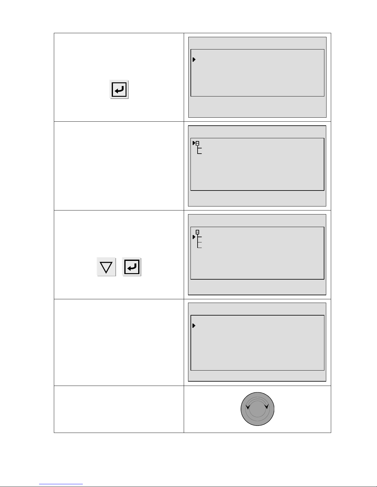
Chapter 3 – Start-up and settings
UM-18400E-U ATEQ F580 User manual Page 59/168
Next access the "FUNCTIONS" menu
of the head and confirm with the
"ENTER" key.
PARAMETERS
PARAMETERS
FUNCTIONS
Copy-Paste
11:10:0124/07
/2002
Validate by "YES" chosen the fill mode.
The cursor being in front of the test
type, validate with the "ENTER" key.
PARAMETERS
FILL MODE : YES
FILL MODE : STANDARD
FILL REGULATOR : 1
11:13:12 24/07/2002
Then enter in the "FILL MODE" menu
and select the "INSTRUCTION"
function. The instruction value appears,
enter the value of the hoped pressure
instruction.
(In general, the pressure instruction is
the test pressure).
PARAMETERS
FILL MODE : YES
FILL MODE : INSTRUCTION
FILL INSTRUCTION : 1.000 bar
FILL REGULATOR : 1
11:14:12 24/07/2002
When the function is activated, from
now on, when the instrument is
carrying out a cycle, it will stop the
fill when the target point is reached.
RUN
RUN PROGRAMME : Pr01 LEAK TEST
SPECIAL CYCLE : Regulator 1
11:14:12 24/07/2002
Launch a regulator setting special
cycle.
Turn the regulator wheel to pressurise.
Take the pressure value above the
target point.
_
+
Page 70

Chapter 3 – Start-up and settings
UM-18400E-U ATEQ F580 User manual Page 60/168
9.3. SETTING A FILLING INSTRUCTION WITH AN ELECTRONIC REGULATOR
9.3.1. Pressure adjust
When instrument is fitted with an electronic regulator, the test pressure value is that
shown since this is the fill target. No special cycle is required..
To enter a fill target see the previous section.
Note: the input pressure for an instrument with electronic regulator must be at least 100
kPa (1 bar) greater than test pressure.
10. STOPPING A CYCLE
Press the RESET key to stop
the measurement in progress.
The instrument is stopping his
cycle and configured for a new
measurement test.
Page 71
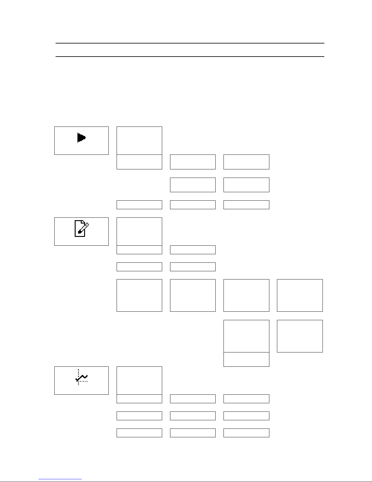
Chapter 4 Functions of the instrument
UM-18400E-U ATEQ F580 User manual Page 61/168
Chapter 4
FUNCTIONS OF THE INSTRUMENT
1. CENTRAL
1.1. MENU STRUCTURE
MAIN MENU Under menu 1 Under menu 2 Under menu 3 Under menu 4
RUN
> Central
v
Head* number > Run program >
Programs
01 to 64
v
v v
v
v Special cycle >
Special cycles
menu
v
v
v
Start key > Head* number > Yes/No
v
PARAMETERS
> Central
v
Copy > Head* number
v
v
v
Paste > Head* number
v
v
v
Head* number >
Programs
01 to 64
> Parameters >
The parameters
regarding the
measurement
head* are
displayed
v
v
v
Functions >
The functions
regarding the
head*
measurement are
displayed
v
Copy-Paste
programs
DISPLAY
> Central
v
Standard > Yes/No > Head* number
v
v
v
Compact > Yes/No > Head* number
v
v
v
Results > Yes/No > Head* number
v
v
Page 72
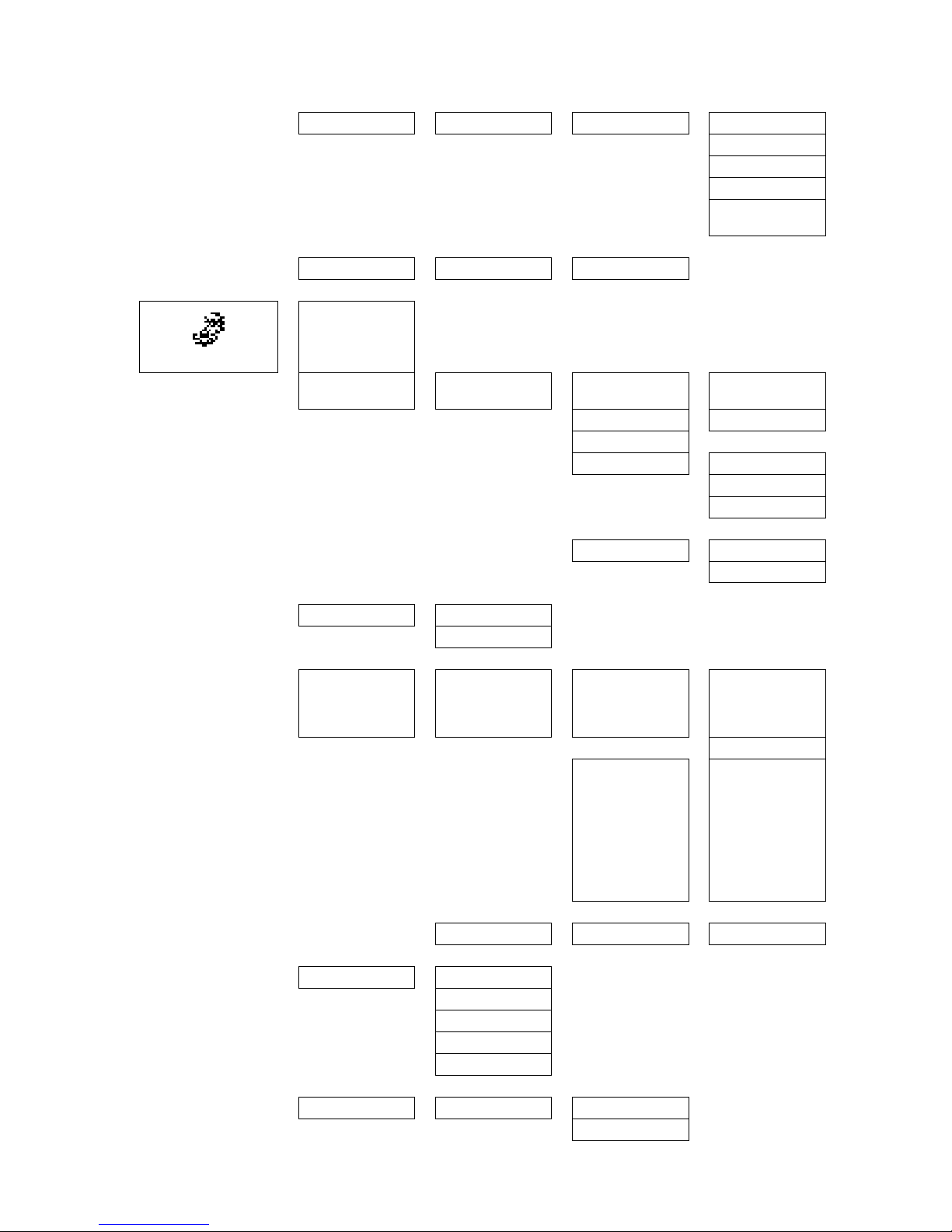
Chapter 4 Functions of the instrument
UM-18400E-U ATEQ F580 User manual Page 62/168
v
Curve > Yes/No > Head* number > Program
v
v Sensor
v
v Acquisition
v
v Mode
v
v
(Recording
Disabled)
v
v
v
L.E.D. display > Head* number > Yes/No
v
v
CONFIG
> Central
v
Network > Install >
Head*
measurement
> Number
v
v I/O Module Number
v
v Identification
v
v I/O Mode > Extended
v
v v Standard
v
v v Compact
v
v v
v
v I/O Distribution > Module n°1
v
v Module n°X
v
v
v
Language > English
v
v Français
v
v
v
Printer > RS Parameters > Speed >
4800 > 9600 >
19200 > 28800 >
38400 > 57600 >
115200
v v
v
v v Format >
1
st
-7bit-="0" > 1st-
7bit-="1" > 1
st
-
7bit-paire > 1
st
-
7bit-impaire > 1
st
-
8bit-sans > 1
st
-
8bit-="0" > 1
st
-
8bit-="1" > 1
st
-
8bit-paire > 1
st
-
8bit-impaire
v
v v
v
v Head* selection > Head* number > Yes/No
v
v
v
Hour > Hour
v
v Minute
v
v Day
v
v Month
v
v Year
v
v
v
Backlight > Mode > Continuous
v
v v Manual
Page 73
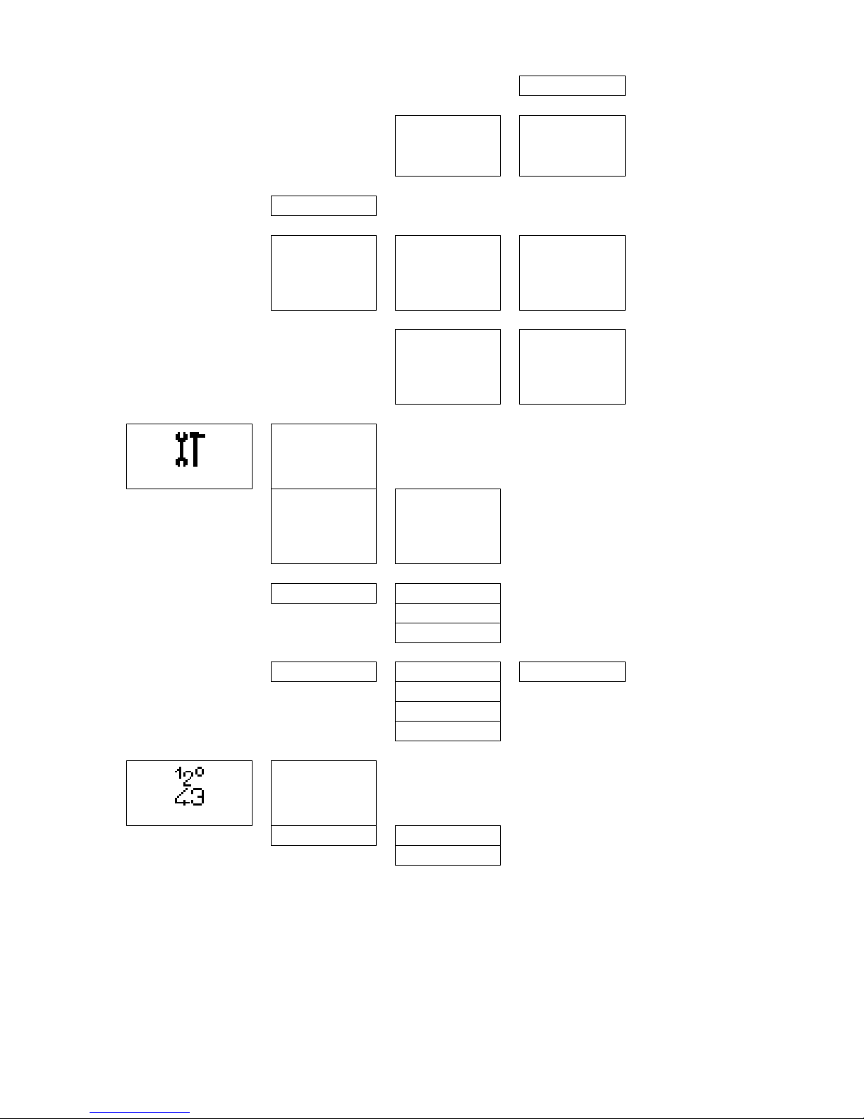
Chapter 4 Functions of the instrument
UM-18400E-U ATEQ F580 User manual Page 63/168
v
v v Auto
v
v v
v
v Intensity >
0 % > 15% > 30%
> 45% > 50% >
70% > 90% >
100%
v
v
v
Head* name
v
v
v
Head* > Extended menus >
The extended
menus regarding
the head*
measurement are
displayed
v
Configuration >
The configuration
regarding the
head*
measurement is
displayed
v
SERVICE
> Central
v
Head* number >
The service menu
regarding the
head*
measurement is
displayed
v
v
v
Parameters > Reset
v
v Recall
v
v Save
v
v
v
Network > Properties > Head* number
v
Network status
v
I/O status
v
Remove
v
RESULTS
> Central
Results > General
Head* number
Note: the parameters which appear in EXTENDED MENUS will be found in the
FUNCTIONS menu when they are activated.
* A head is a single measurement unit (one instrument can contain more than one
head/measurement unit such as an F580).
Page 74

Chapter 4 Functions of the instrument
UM-18400E-U ATEQ F580 User manual Page 64/168
1.2. RUN MENU
The "RUN" menu allows the management of measurement unit test cycles.
1.2.1. Unit (head) XX
For more comprehensive information concerning the measurement units’ cycles, refer to
their user manuals.
1.2.1. 1) Active program
To access the active program of the measurement unit and choose a program amongst
the existing ones.
1.2.1. 2) Special cycle
To select the special cycle to be started in the measurement unit, refer to paragraph 3
of this chapter.
1.2.2. "START" key
The confirmation with a "YES" allows the starting of a test cycle or special cycle on the
corresponding unit with the cycle start key of the central.
This function enables the carrying out of test or special cycles on a few or all of the
measurement units from the central unit.
Depending on the position in the menus, the test program (or special cycle) is started on
the measurement unit, or on all the measurement units selected in the "START KEY"
menu. Refer to chapter 3, paragraph 7 "Launching a cycle".
Page 75

Chapter 4 Functions of the instrument
UM-18400E-U ATEQ F580 User manual Page 65/168
1.3. PARAMETERS MENU
The "PARAMETERS" menu enables the management of the measurement units’ test
parameters.
For more detailed information concerning the measurement units’ parameters, refer to
their user manuals.
1.3.1. Copy Paste
This function has for aim to recover the test parameters of a measurement unit to insert
them into another measurement unit.
To use this function, the measurement units must absolutely be identical, in their
test type, configuration and in their software and hardware versions. If the copy paste
operation is not valid, the instrument does not authorise the function to avoid the
entering of parameters from one unit into another but different unit.
1.3.2. Measurement unit (head) XX
To manage the test cycles inside a measurement unit, refer to its user manual.
When entering the "HEAD XX" menu, after having chosen the program number, it is
possible to modify the set of parameters of the program for the chosen unit.
Page 76
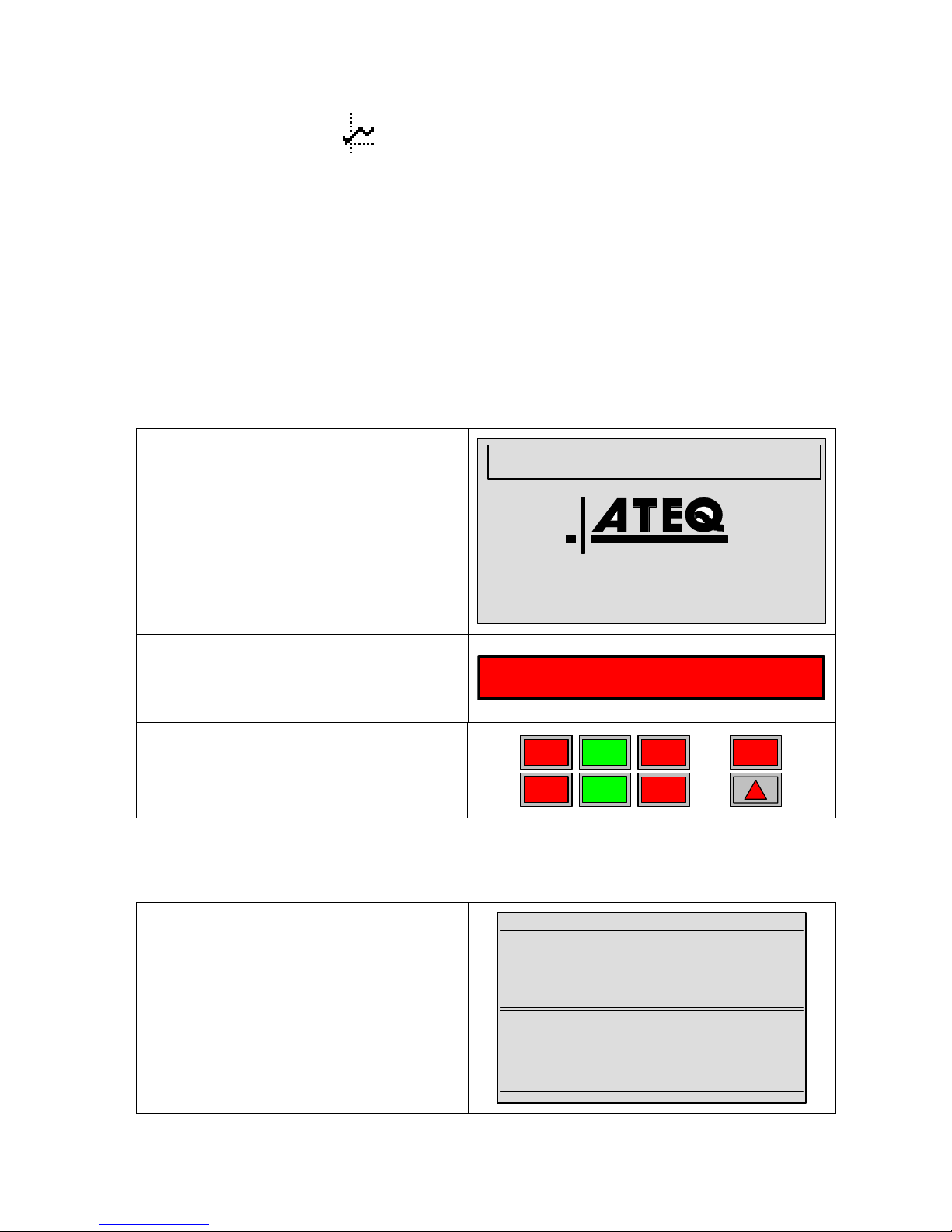
Chapter 4 Functions of the instrument
UM-18400E-U ATEQ F580 User manual Page 66/168
1.4. DISPLAY MENU
This menu manages the central unit display, also known as the L.C.D. and L.E.D.
displays.
When the display mode of one or more unit(s) is selected and confirmed with a "YES",
the screen displays the state of the measurement unit(s) identically to the "4 line"
displays of the measurement units which have them fitted.
For more information, refer to the user manual of the measurement unit concerned.
1.4.1. No display
In this mode, when the display of the measurement unit(s) mode is not selected, the
instrument only displays the minimum necessary, which is:
On the L.C.D. display:
¾ the type of instrument,
¾ the type of software,
C 540 VX.XXi
WWW.ATEQ.COM
ON the L.E.D. display:
¾ the company, ATEQ,
¾ the instrument type,
ATEQ F580
The results and alarm indicators remain
switched off.
R1
R2
1.4.2. "STANDARD" display
In this mode the measurement units are displayed in the 4 line style.
Example with two measurement units:
In this mode it is possible to display a
maximum of four measurement units.
ATEQ C540
---- H01 ---RUN/Pr:001
PRESS = 1.50 bar
LEAK = 005 Pa
READY (OK)
---- H02 ---RUN/Pr:001
PRESS = 2.00 bar
LEAK = 004 Pa
READY (OK)
Page 77
Chapter 4 Functions of the instrument
UM-18400E-U ATEQ F580 User manual Page 67/168
1.4.3. "COMPACT" display
This display enables the visualisation of summarised measurement unit results, this
includes the good or bad part result for each measurement unit.
Example with two measurement units:
In this mode, it is possible to display a
maximum of 10 measurement units (Hxx).
ATEQ C540
OK H01 NOK
OK H02 NOK
11:56:57 01/07/2002
Display of the results:
Good part result:
OK
H
01 NOK
Bad part result:
NOK
OK T01
Warning:
OK T01
NOK
1.4.4. "RESULTS" display
This display mode writes the result at the end of each cycle for the measurement units
(HXX) selected.
In these results there is the measurement unit number (Hxx), test result and
measurements.
Example:
ATEQ C540
H01 01 (OK) 010 Pa 300.8 mbar
H02 01 (OK) 001 Pa 200.0 mbar
H01 01 (OK) 022 Pa 301.2 mbar
H02 01 (OK) 005 Pa 201.4 mbar
H01 01 (OK) 018 Pa 299.5 mbar
H02 01 (OK) 007 Pa 202.2 mbar
H01 01 (OK) 002 Pa 300.1 mbar
H02 01 (OK) 001 Pa 199.4 mbar
H01 01 (OK) 011 Pa 300.4 mbar
H02 01 (OK) 012 Pa 200.4 mbar
11:56:57
01/07/2002
Page 78
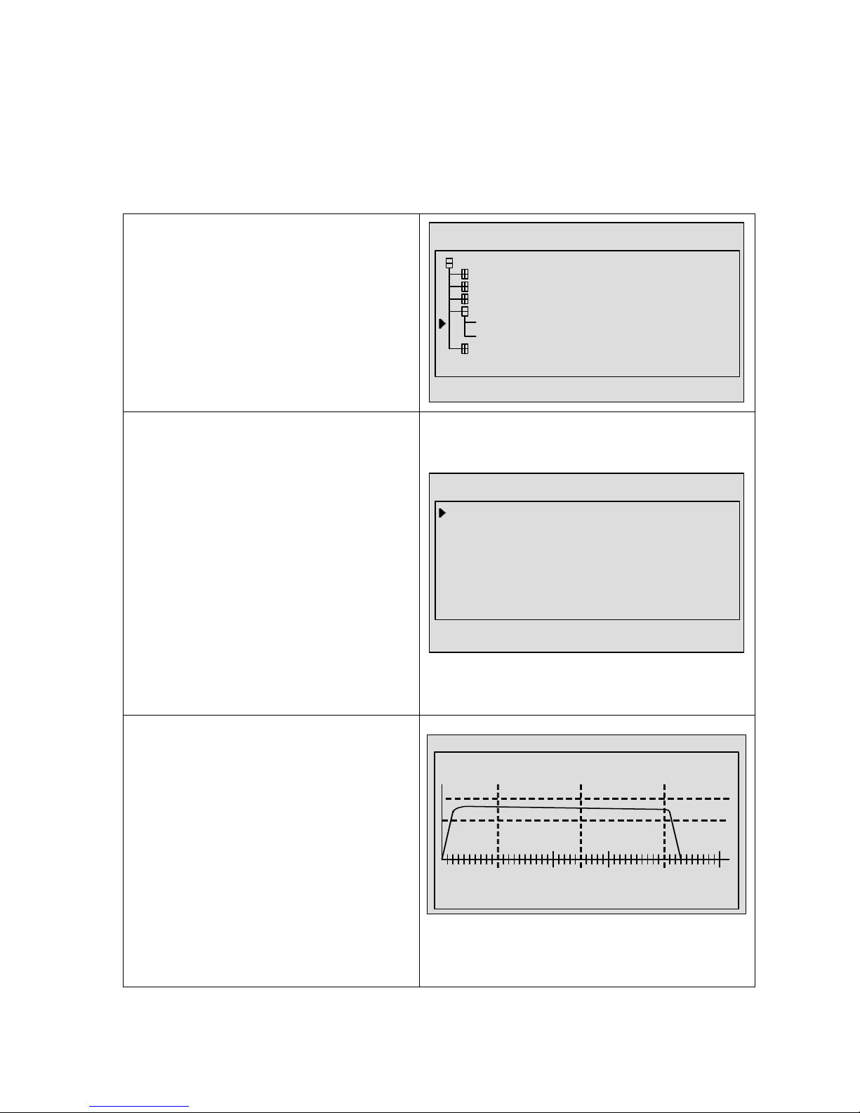
Chapter 4 Functions of the instrument
UM-18400E-U ATEQ F580 User manual Page 68/168
1.4.5. "CURVE" display
This mode allows the live display of the test curves of a measurement unit. It is only
possible to display the curve of one measurement unit (Head) at a time. When a
measurement unit is selected it cancels the others automatically.
Curve display procedure:
In the "DISPLAY" menu, select the
"CURVE" menu, then select "YES" to
confirm the display of the unit.
DISPLAY
CENTRAL
STANDARD : NO
COMPACT : NO
RESULTS : NO
CURVE : YES
HEAD 01 : YES
HEAD 02 : NO
LED DISPLAY : NO
11:02:59 18/06/2002
Next, set the parameters for the
acquisition and display of the curve:
Program: to select the test program.
Sensor: to select the sensor.
Acquisition: to select the
measurement point acquisition speed
(normal, average, fast, turbo).
Mode: to chose the display of a single
cycle or continuously (for the "ONE
CYCLE" mode the display will only be
for the selected cycle, for the
"CONTINUOUS" mode, the curve will
be displayed and reset with each cycle
start.
DISPLAY
PROGRAM : Pr:01 LEAK TEST
SENSOR : TEST PRESSURE
ACQUISITION : NORMAL
MODE : ONE CYCLE
RECORDING ENABLED
11:03:39 18/06/2002
Once the parameters have been
entered, if we press on the "START"
key, then only the selected
measurement unit carries out its test
cycle start, the next time the "START"
key is pressed all the measurement
units carry out their test cycles.
To make all the measurement units
carry out their test cycle on demand,
press on the "C" key before pressing on
the "START" key
A curve is then displayed live. To the
right is an example of the pressure
sensor display.
ATEQ C540
3.750 bar
0.000 bar STEP x = 0.1 s
HEAD 01 : F5 :
Note: The thresholds are placed
automatically depending on the reject levels.
Page 79
Chapter 4 Functions of the instrument
UM-18400E-U ATEQ F580 User manual Page 69/168
1.4.6. "L.E.D." display
This menu allows the display of the test results for a selected measurement unit, on the
alphanumeric 14 character display as well as on the L.E.D. results indicators.
The alphanumeric display shows the state of the measurement unit in and out of cycle.
The LED display shows the state of a test part, good, bad in test or reference, as well as
alarms.
For the text and indicator displays refer to the user manuals of the measurement units
concerned.
14 character L.E.D. display:
READY
Results and warning indicators:
R1
R2
Page 80
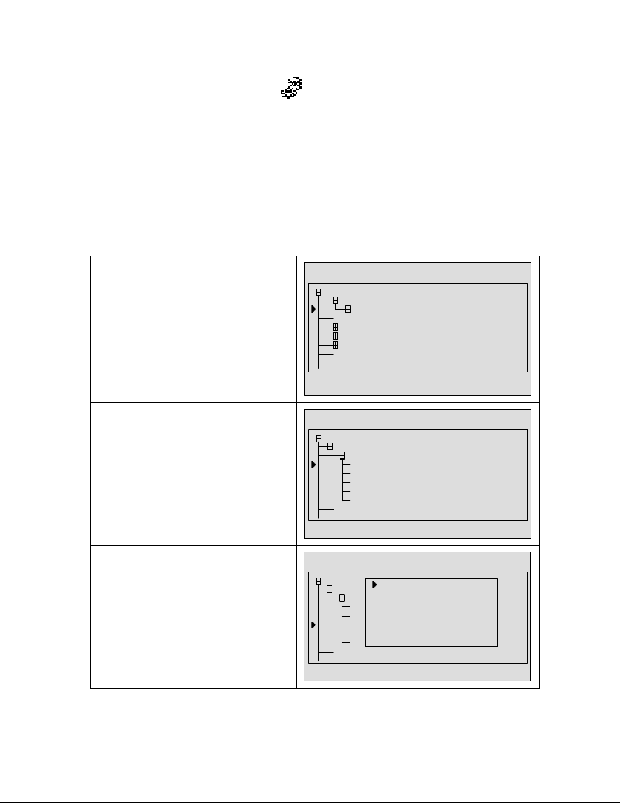
Chapter 4 Functions of the instrument
UM-18400E-U ATEQ F580 User manual Page 70/168
1.5. CONFIGURATION MENU
This menu allows the configuration of the central, the entire network as well as the
accessories when they are used.
1.5.1. "NETWORK" menu
1.5.1. 1) "INSTALLATION" menu
This menu enables the configuration of the network during its installation or its servicing.
For the installation of the network, refer to chapter 3, paragraph 2 "Start-up of the
network".
Use the navigation keys to move the
cursor till it is in front of the
"INSTALLATION" menu then confirm
with ENTER.
CONFIG
CENTRAL
NETWORK
INSTALL
LANGUAGE : ENGLISH
PRINTER
HOUR
BACKLIGHT
HEAD NAME
HEAD 01 : F5 :
10:5
9:3218/06/2002
In the "Head (measurement unit)"
menu it is necessary to indicate the
quantity of measurement units which
are installed in the network.
See chapter 3, paragraph 2 "Start-up
of the network".
CONFIG
CENTRAL
NETWORK
INSTALL
HEAD : 02
I/O MODULES : 01
IDENTIFICATION
I/O MODE : EXTENDED
I/O DISTRIBUTION
LANGUAGE : ENGLISH
11:02:59 18/06/2002
Choice of the outputs mode: place the
cursor in front of "I/O MODE" then
confirm, a window appears, choose
between the three modes and confirm.
See chapter 3, paragraph 3 "Allocation
of the outputs".
CONFIG
CENTRAL
NETWORK
INSTALL
HEAD : 01
I/O MODULES : 01
I/O MODE : ETENDU
I/O DISTRIBUTION
IDENTIFICATION
LANGUAGE : ENGLISH
11:08:13 18/06/2002
EXTENDED
STANDARD
COMPACT
Page 81

Chapter 4 Functions of the instrument
UM-18400E-U ATEQ F580 User manual Page 71/168
In the "I/O DISTRIBUTION" menu, a
list of measurement units (heads) and
their allocation to the modules
appears. See chapter 3, paragraph 3
"Allocation of the outputs".
CONFIG
MODULE 1 : HEAD 01
MODULE 2 : HEAD 02
11:0
8:13
18/06/2002
Using the up and down arrows, place
the cursor in front of
"IDENTIFICATION" and validate. See
chapter 3, paragraph 2 "Start-up of the
network".
CONFIG
CENTRAL
NETWORK
INSTALL
HEAD : 02
I/O MODULES : 01
IDENTIFICATION
I/O MODE : EXTENDED
I/O DISTRIBUTION
LANGUAGE : ENGLISH
11:08:13 18/06/2002
1.5.2. "LANGUAGE" menu
This menu enables the choosing of the language displayed on the screen. Several
languages are available. Two are installed when the instrument is manufactured, with
English being the default language and the other as chosen by the customer.
Access to the "LANGUAGE" menu and
modification of the language if
necessary.
CONFIG
CENTRAL
NETWORK
INSTALL
HEAD : 02
I/O MODULES : 01
IDENTIFICATION
I/O MODE : EXTENDED
I/O DISTRIBUTION
LANGUAGE : ENGLISH
11:06:45 18/06/2002
ENGLISH
FRANCAIS
Page 82

Chapter 4 Functions of the instrument
UM-18400E-U ATEQ F580 User manual Page 72/168
1.5.3. "PRINTER" menu
1.5.3. 1) RS Parameters
This menu enables the configuration of the communication port for the connection of a
printer (or a laptop) to make the exportation of results frames possible.
The printer must be connected to the J1 connector.
The "RS parameters/speed" enables the choice of the speed.
The "parameters RS/format" menu allows the choosing of the format of the bytes sent.
To know the forms of the different print frames, refer to the measurement unit manuals.
Note: the central will only print depending on the individual configuration of each
measurement unit.
1.5.3. 2) "HEAD SELECTION" menu
This menu allows the selection of the measurement unit(s) (head) for which the results
will be sent in the print frame. To select the units, confirm with a "YES".
The units selected will not print on their own serial port. The frames print format
has to be configured in each unit. Frame example with a good part and the pressure
1 2 3 4 5 6 7 8 9 10 11 12 13 14 15 16 17 18 19 20 21 22 23 24 25 26 27 28 29 30 31 32 33 34 35 36 37 38 39 40
< 0 1 > : 1 . 0 2 b a r : ( O K ) : + 0 0 2 P a
1.5.4. "HOUR" menu
This menu allows the setting of the hour and date parameters of the instrument.
1.5.5. "LIGHT" menu
This menu allows the configuration of the L.C.D. display.
The lighting of the display can be programmed and can be modified. It should be
adjusted depending on the surrounding lighting conditions or according tot the
preferences of the operator.
Three light modes are available:
9 permanent mode, permanent lighting of the display.
9 manual mode, the display remains lit for 20 minutes, if after this time, no entries
have been made on the instrument the screen light switches off it will light up
again as soon as a key is pressed on the front panel.
9 automatic mode, it is identical to the manual mode, with lighting of the display if
an action is made on the external inputs as well (rear panel connectors).
In these three modes, the intensity of the light is programmable from 0 % (screen off) up
to 100 % (maximum light intensity).
Page 83
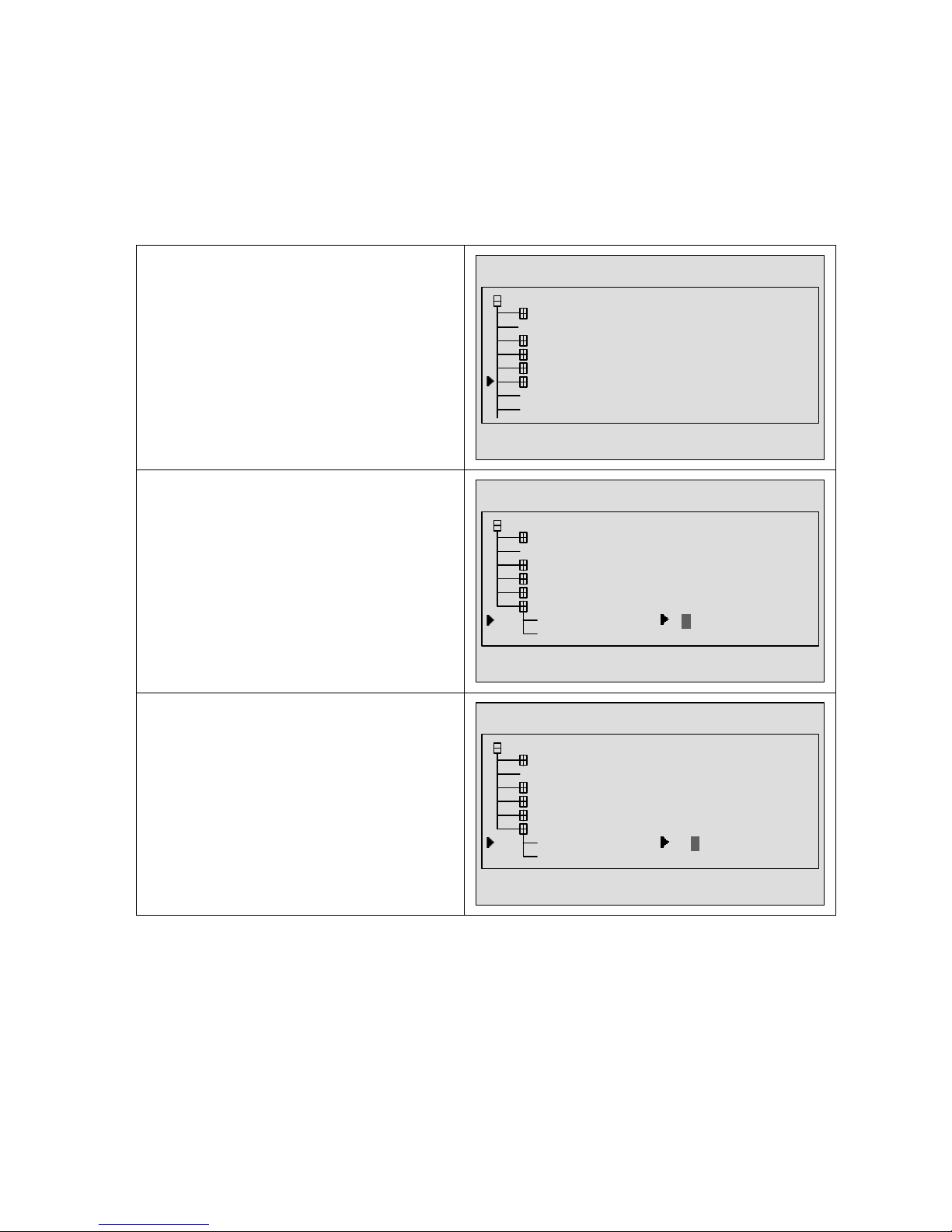
Chapter 4 Functions of the instrument
UM-18400E-U ATEQ F580 User manual Page 73/168
1.5.6. "HEAD NAME" menu
This menu allows the operator to set name(s) for the measurement unit(s) (head) to
identify and recognise them more easily.
This name can be found in the "CURVE" display.
Follow the procedure bellow to set the name of a measurement unit.
Using the "UP" and "DOWN" keys,
place the cursor in front of the
measurement unit to be named.
CONFIG
CENTRAL
NETWORK
LANGUAGE : ENGLISH
PRINTER
HOUR
BACKLIGHT
HEAD NAME
HEAD 01 : F5 :
HEAD 02 : F5 :
10:5
9:3218/06/2002
Confirm with the “ENTER" key, the
cursor places itself on the right. Using
the "UP" and "DOWN" keys, choose the
alphanumeric character.
CONFIG
CENTRAL
NETWORK
LANGUAGE : ENGLISH
PRINTER
HOUR
BACKLIGHT
HEAD NAME
HEAD 01 A
HEAD 02 :
09:55:22 02/07/2002
When the required character is
displayed, move to the next with the
"RIGHT ARROW".
It is possible to move back to previous
characters with the "LEFT ARROW".
Once the whole name is entered,
confirm with the "ENTER" key.
CONFIG
CENTRAL
NETWORK
LANGUAGE : ENGLISH
PRINTER
HOUR
BACKLIGHT
HEAD NAME
HEAD 01 AB
HEAD 02 :
05:55:45 02/07/2002
Note: maximum number of characters for the name of a unit: 13.
1.5.7. "HEAD XX" menu
This menu accesses the configuration and extended menus of the measurement units.
For more information refer to the user manual for the measurement unit concerned.
Page 84
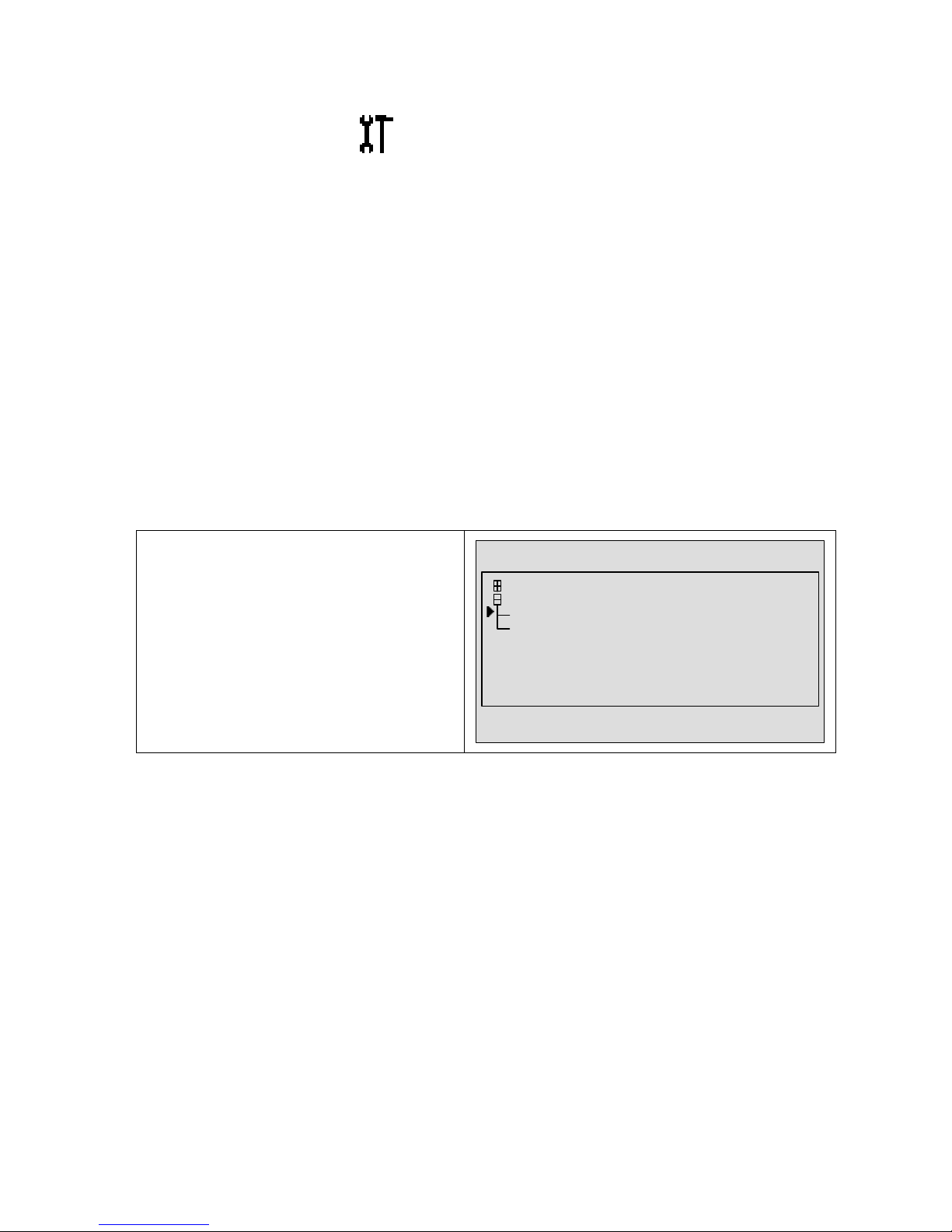
Chapter 4 Functions of the instrument
UM-18400E-U ATEQ F580 User manual Page 74/168
1.6. SERVICE MENU
This menu gives access to the servicing of the measurement unit(s), their parameters
and the network.
1.6.1. Servicing of the measurement unit
1.6.1. 1) Servicing of the measurement unit parameters
This menu allows the saving, the recovery or the deletion of the test cycle parameters of
a measurement unit.
9 DELETE menu: allows the deletion of all the parameters.
9 RECOVERY menu: allows the recovery of all the parameters.
9 SAVE menu: allows the saving of all the parameters.
1.6.1. 2) Servicing of the sensors
This menu allows the monitoring of the information supplied by the sensors.
The screen displays the gross values
measured by the pressure sensors.
SERVICE
PARAMETERS
SENSOR
LEAK : 0052
PRESSURE : 0001
10:29:45 02/07/2002
1.6.1. 3) Servicing of the central parameters
This menu allows the saving, recovery or deletion of the C540 central module
parameters. This menu only appears when the key is in the "ACCESS" position.
9 DELETE menu: allows the deletion of all the parameters.
9 RECOVERY menu: allows the recovery of all the parameters.
9 SAVE menu: allows the saving of all the parameters.
Page 85
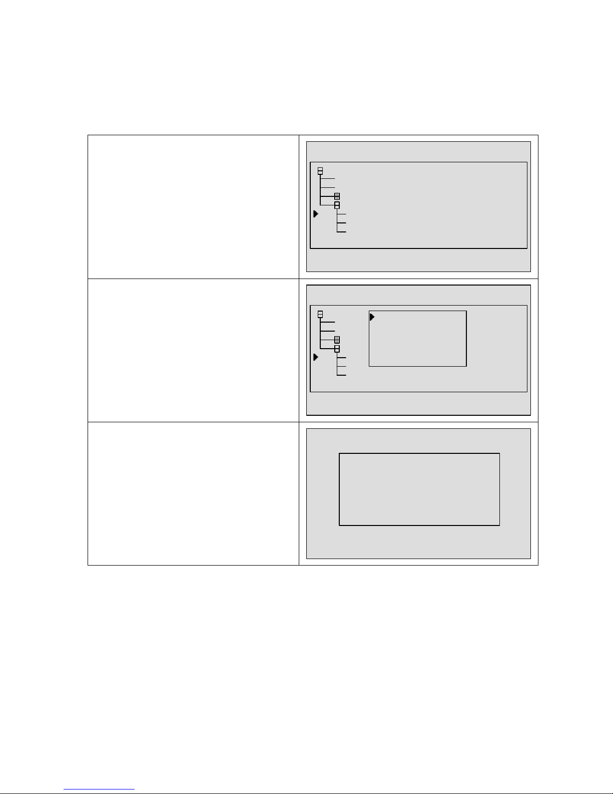
Chapter 4 Functions of the instrument
UM-18400E-U ATEQ F580 User manual Page 75/168
1.6.2. Network servicing
1.6.2. 1) "PROPERTIES" menu
In this menu the characteristics of the selected measurement unit are selected.
Enter the "PROPERTIES" menu.
SERVICE
CENTRAL
HEAD 01 : F5 : HEADX1
HEAD 02 : F5 : HEADX2
PARAMETERS
NETWORK
PROPERTIES
NETWORK STATUS
I/O STATUS
REMOVE
09:54:02 02/07/2002
Choose the measurement unit (head) to
be displayed.
SERVICE
CENTRAL
HEAD 01 : F5 : HEADX1
HEAD 02 : F5 : HEAD2
PARAMETERS
NETWORK
PROPERTIES
NETWORK STATUS
I/O STATUS
REMOVE
09:54:02 02/07/2002
HEAD 01 :F5
HEAD 02 :F5
The properties and characteristics of
the measurement unit (head) are
displayed.
PROPERTIES
HEAD 01 :
ATEQ F5
Version 01.15c
0-> 5000 mbar
Diff. F. Sc. 500 Pa
Page 86
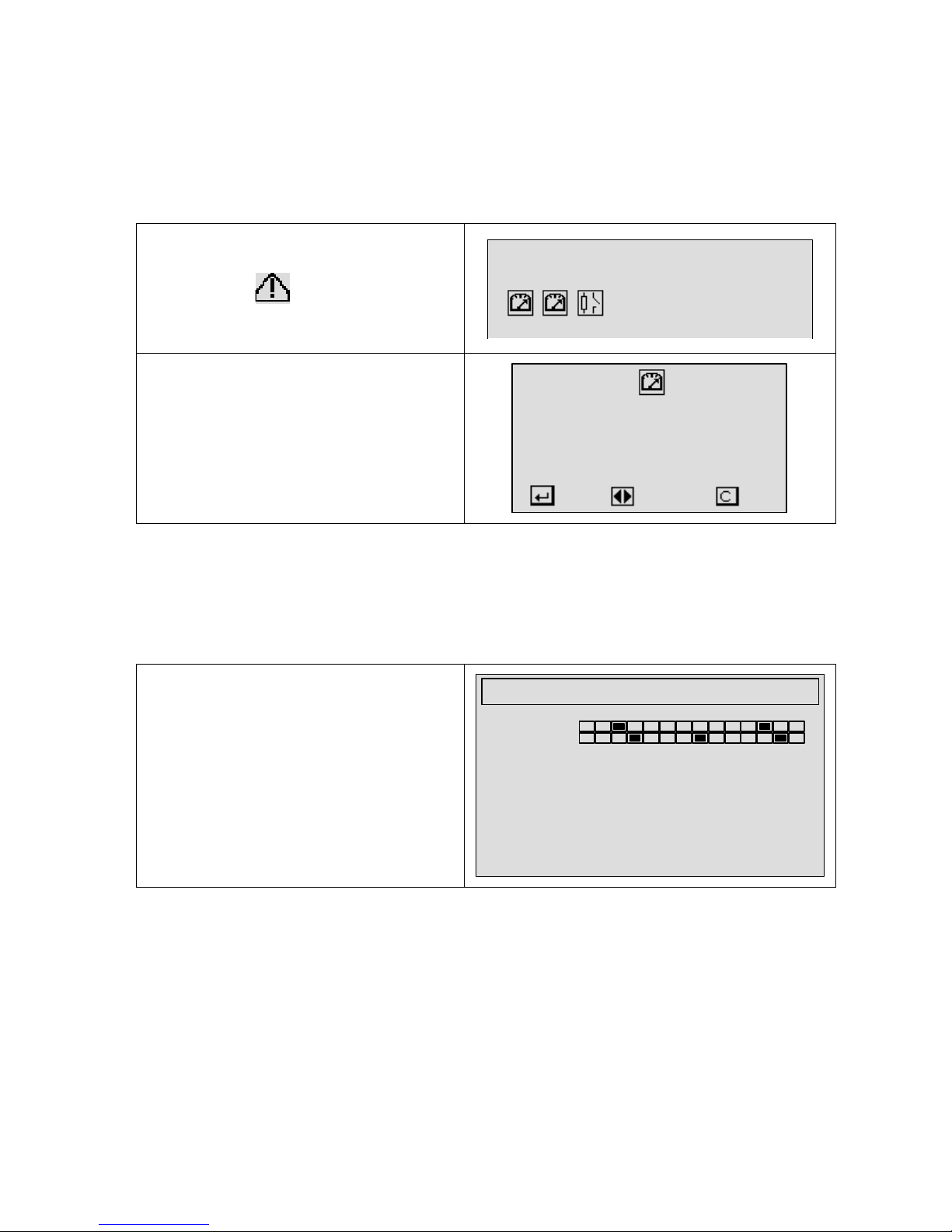
Chapter 4 Functions of the instrument
UM-18400E-U ATEQ F580 User manual Page 76/168
1.6.2. 2) "NETWORK STATUS" menu
This menu displays the operational, communication and measurement unit conditions of
the network (counting of the errors and communication fails).
In good communication conditions, the "time out" and "crc" counters must stay at 0
(zero), the "transaction" counters must evolve continually.
Display of the status of the network.
In the event of a unit communication
problem, the icon appears where
the measurement unit (head) is
displayed.
NETWORK STATUS
H01 H02 H03
F5 F5 INT
In the network status mode, when the
ENTER key is pressed, the network
measurement unit communications
status appears.
The display of the other elements is
activated by pressing on the left and
right arrows.
H01: F5 :
TIME OUT CRC COM
00000 00000 0221232
R
ESET
NEXT END
On the first installation, it is necessary to configure the network, refer to Chapter 3
paragraph 2. "Start-up of the network".
1.6.2. 3) "I/O STATUS" menu
This menu allows the display the status of the J7 (all or nothing outputs) and J8 (inputs)
connector inputs and outputs.
Enter the "I/O STATUS" menu. The
validated outputs and inputs are
represented by a black rectangle.
I/O STATUS
1 14
INPUTS
OUTPUTS
Page 87
Chapter 4 Functions of the instrument
UM-18400E-U ATEQ F580 User manual Page 77/168
1.6.2. 4) "REMOVE" menu
This menu enables the management of the measurement units (heads) in the network,
but also to delete them when they are no longer required.
Enter the "NETWORK SERVICE
REMOVE" menu and confirm.
SERVICE
CENTRAL
HEAD 01 : F5 : HEADX1
HEAD 02 : F5 : HEADX2
PARAMETERS
NETWORK
PROPERTIES
NETWORK STATUS
REMOVE
16:40:36 20/08/2002
Next, select the measurement unit
(head) to be deleted from the network.
SERVICE
CENTRAL
HEAD 01 : F5 : HEADX1
HEAD 02 : F5 : HEADX2
PARAMETERS
NETWORK
PROPERTIES
NETWORK STATUS
ADD
REMOVE
09:54:02 02/07/2002
HEAD01 :F5
HEAD02 :F5
HEAD03 :I/O
In the event of a measurement unit (head) being removed in the network, it remains
available in the event of an ulterior usage. The "ADD" menu then appears in the list.
In the event of a definitive deletion of a measurement unit, you must reinitiate the
network and identify the measurement units (heads) one by one, refer to paragraph
1.5.1.1) "Installation menu".
Page 88
Chapter 4 Functions of the instrument
UM-18400E-U ATEQ F580 User manual Page 78/168
1.6.2. 5) "ADD" menu
This menu enables the addition of a measurement unit (head) in the network. To do so,
follow the procedure below:
Switch off the instrument or ensure that it is switched off.
Physically add one
measurement unit in the network (cabling).
Switch on the central, the network starts
up.
C 540 VX.XXi
STARTUP
Enter the "NETWORK SERVICE ADD"
menu and confirm.
SERVICE
CENTRAL
HEAD 01 : F5 : HEADX1
HEAD 02 : F5 : HEADX2
PARAMETERS
NETWORK
PROPERTIES
NETWORK STATUS
ADD
REMOVE
09:54:02 02/07/2002
Next, select the measurement unit
(head) to be added in the network.
SERVICE
CENTRAL
HEAD 01 : F5 : HEADX1
HEAD 02 : F5 : HEADX2
PARAMETERS
NETWORK
PROPERTIES
NETWORK STATUS
ADD
REMOVE
09:54:02 02/07/2002
HEAD01 :F5
HEAD02 :F5
HEAD03 :I/O
Page 89
Chapter 4 Functions of the instrument
UM-18400E-U ATEQ F580 User manual Page 79/168
1.6.2. 6) "REPLACE" menu
This menu allows the replacing of one measurement unit in the network by another in
the event of a breakdown for example.
This operation can only be carried out if the replacement unit if absolutely identical to
that which it is replacing (hardware and software version).
Switch off the instrument or make sure it is off.
Physically add the replacement measurement unit in the network
(cabling).
Switch on the central, the network
initiates.
C 540 VX.XXi
STARTUP
Enter the "NETWORK MAINTENACE
REPLACE" menu and confirm.
SERVICE
PARAMETERS
NETWORK
PROPERTIES
NETWORK STATUS
I/O STATUS
ADD
REPLACE
WITHOUT PARA.
REMOVE
16:36:26 24/07/2002
The replacement "with parameters"
allows the transfer of the programs
contained in the old unit to the new unit.
The replacement "without parameters"
allows the changing of a unit without
transferring the parameters, the
parameters of the new unit are
conserved or they must entered if they
have not been created
SERVICE
PARAMETERS
NETWORK
PROPERTIES
NETWORK STATUS
ADD
REPLACE
WITHOUT PARA.
WITH PARA.
REMOVE
16:38:21 24/07/2002
Page 90
Chapter 4 Functions of the instrument
UM-18400E-U ATEQ F580 User manual Page 80/168
Next, select the measurement unit
(head) to be added to the network and
confirm.
SERVICE
PARAMETERS
NETWORK
PROPERTIES
NETWORK STATUS
ADD
REPLACE
WITHOUT PARA.
WITH PARA.
REMOVE
16:39:16 24/07/2002
HEAD01 :F5
The central automatically changes the
unit (head), The network is then ready
again.
SERVICE
PARAMETERS
NETWORK
PROPERTIES
NETWORK STATUS
ADD
REPLACE
WITHOUT PARA.
WITH PARA.
REMOVE
16:41:56 24/07/2002
Switch off the instrument, or ensure that it is switched off.
Physically remove the replaced head from the network (cabling).
Page 91
Chapter 4 Functions of the instrument
UM-18400E-U ATEQ F580 User manual Page 81/168
1.7. RESULTS MENU
This menu allows the display of the results measured by the different measurement
units.
In this menu the 64 last results of all the heads are conserved.
In the "RESULTS/GENERAL" menu, all the measurements of all the units will be
displayed.
In the "RESULTS/HEADXX" menu, all the measurements of the corresponding
measurement unit (head) will be displayed.
In the display of the results you will find:
9 the number of the unit,
9 le number of the program,
9 the test result,
9 the measurements.
In the display of the test results, there is: POK, good part; PNOK, test error; AL, alarm.
On the current display, the last 9 results
are displayed.
RESULTS
H01 01 (OK)° 053 Pa 1.99 bar
H02 01 (OK)° 002 Pa 792.9 mbar
H01 01 (OK)° 057 Pa 1.99 bar
H02 01 (OK)° 003 Pa 794.8 mbar
H01 01 (OK)° 056 Pa 1.99 bar
H02 01 (OK)° 001 Pa 796.0 mbar
H01 01 (OK)° 051 Pa 1.99 bar
H02 01 (OK)° 000 Pa 798.7 mbar
H01 01 (OK)° 048 Pa 1.99 bar
15:33:32 08/07/2002
If the "ENTER" key is pressed, a
window opens, it is then possible to
manage the results.
PRINT: to send the results and the time
stamping to the printer which is
connected to the central.
RESET: to definitively erase the results
displayed on the screen.
RESULTS
H01 01 (OK)° 053 Pa 1.99 bar
H02 01 (OK)° 002 Pa 792.9 mbar
H01 01 (OK)° 057 Pa 1.99 bar
H02 01 (OK)° 003 Pa 794.8 mbar
H01 01 (OK)° 056 Pa 1.99 bar
H02 01 (OK)° 001 Pa 796.0 mbar
H01 01 (OK)° 051 Pa 1.99 bar
H02 01 (OK)° 000 Pa 798.7 mbar
H01 01 (OK)° 048 Pa 1.99 bar
15:33:32 08/07/2002
PRINT
RESET
Page 92

Chapter 4 – Functions of the instrument
UM-18400E-U ATEQ F580 User manual Page 82/168
2. F5 HEAD
2.1. MENU STRUCTURE
2.1.1. Main menu
MAIN MENU Sub menu 1 Sub menu 2 Sub menu 3 Sub menu 4
RUN PROGRAM
> 1 to 16
v
PARAMETERS
> Copy Paste > Copy
v
v Paste
v
v
v
Programs
01 to 16
> LEAK TEST > Type: Leak test > Delete name
v
v Auto setup Reset program
v
v Coupling time A
Delete custom
name
v
v Fill time
v
v Stabilisation time
v
v Test time
v
v Dump time
v
v Pressure unit >
Bar > MPa > kPa
> Pa > PSI >
mbar
v
v Maximum fill
v
v Minimum fill
v
v Set fill instruction
v
v Leak unit >
Pa > Pa/s >
Pa(HR) >
Pa(HR)/s >
Cal-Pa > Cal-Pa/s
> cm
3
/mn > cm3/s
> cm
3
/h > mm3/s
v
v Test fail
v
v Reference fail
v
v Functions > Refer to note
v
v
v
BLOCKAGE > Type: Blockage > Delete name
v
v Coupling time A Reset program
v
v Fill time
v
v Dump time
v
v Pressure unit >
Bar > MPa > kPa
> Pa > PSI >
mbar
v
v Maximum fill
v
v Minimum fill
v
v Set fill instruction
v
v Functions > Refer to note
v
v
Page 93
Chapter 4 – Functions of the instrument
UM-18400E-U ATEQ F580 User manual Page 83/168
v
v
DESENSITISED >
Type:
desensitised
> Delete name
v
v Coupling time A Reset program
v
v Fill time
v
v Stabilisation time
v
v Test time
v
v Dump time
v
v Pressure unit
v
v Maximum fill
v
v Minimum fill
v
v Set fill instruction
v
v Leak unit
v
v Test fail
v
v Reference fail
v
v Functions > Refer to note
v
v
v
OPERATOR > Type: operator > Delete name
v
Coupling time A Reset program
v
Test time
v
Functions > Refer to note
v
SPECIAL CYCLES
> None
v
Pressure 1
regulator 1 check
v
Pressure 1
regulator 2 check
v
Pressure 2
sensor test
v
Leak sensor
check
v
Auto-test
v
Sensor status
v
Regulator 1
adjust
v
Regulator 2
adjust
v
Infinite fill
v
Piezo auto zero
v
ATR learning
v
Volume compute
v
Custom unit learn
v
Custom unit
check
Verify + custom
unit learn
v
Check test result
v
Sealed PASS
part learn
v
Sealed FAIL part
learn
v
Page 94

Chapter 4 – Functions of the instrument
UM-18400E-U ATEQ F580 User manual Page 84/168
CONFIGURATION
> Extended menus > Name
v
v
Program
sequencing
v
v Units
v
v Filter
v
v
Automatic
connector
v
v Check test
v
v ATR0
v
v ATR1
v
v ATR2
v
v Pre-fill type
v
v Fill mode
v
v Blow mode
v
v Valve codes
v
v 24 V outputs
v
v End of Cycle
v
v Mini valve
v
v Rework limits
v
v Sealed part
v
v Peak hold
v
v
Reference
volume
v
v Volume compute
v
v Stamping
v
v
Temperature
correction 1
v
v Indirect
v
v Sign
v
v Remote control
v
v
v
Automatic save > yes / no
v
v
v
Electronic
regulator
> None
v
v Regulator 1
v
v Regulator 2
v
v All
v
v
v
Regulator control Automatic
v
v External
v
V
v
Auto piezo reset > yes / no >
Number of
minutes
v
v Number de cycles
V
v
V
Pressure unit >
Pa, PSI, mbar,
bar, Mpa,kPa
v
v
Page 95

Chapter 4 – Functions of the instrument
UM-18400E-U ATEQ F580 User manual Page 85/168
v
v
v
Date & Time > Hour
v
V Minute
v
V Day
v
V Month
v
V Year
v
v
v
RS232 > C540/F580 Print frame > Pressure
v
v v Program name
v
v v Date & time
v
v v Lines before
v
v v Lines after
v
v v Inter line
v
v v Form feed
v
v v
v
v Printer > RS parameters >
Speed:
4800 > 9600 >
19200 > 28800 >
38400 > 57600 >
115200
v
v v v
Serial port:
1st-7bit-="0" > 1st-
7bit-="1" > 1
st
-
7bit-even > 1
st
-
7bit-odd > 1
st
-
8bit-none > 1
st
-
8bit-="0" > 1
st
-
8bit-="1" > 1
st
-
8bit-even > 1
st
-
8bit-odd >
v
v v v
v
v v Print frame > Pressure
v
v v v Program name
v
v v v Date & time
v
v v v Lines before
v
v v v Lines after
Inter line
v
v v v Form feed
v
v v v
v
v v Send conditions > All results
v
v v v Pass
v
v v v Test fail
v
v v v Reference fail
v
v v v Alarm
v
v v v Pressure out
v
v v v Re-workable
v
v v v Calibration
v
v v v
v
v v Export > yes / no
v
v v v
v
v v Print parameters
v
v v
Page 96

Chapter 4 – Functions of the instrument
UM-18400E-U ATEQ F580 User manual Page 86/168
v v
v
v Modbus > Address > 255 (fixed)
v
v v
v
v RS parameters >
Speed:
4800 > 9600 >
19200 > 28800 >
38400 > 57600 >
115200
v
v
Serial port:
1st-7bit-="0" >
1st-7bit-="1" >
1st-7bit-even >
1st-7bit-odd >
1st-8bit-none >
1st-8bit-="0" >
1st-8bit-="1" >
1st-8bit-even >
1st-8bit-odd >
v
v
v
RS485 > C540/F580
v
v v
v
v Modbus > Address > 1 to 255
v
v v
v
v RS parameters >
Speed:
4800 > 9600 >
19200 > 28800 >
38400 > 57600 >
115200
v
v
Serial port:
1st-7bit-="0" >
1st-7bit-="1" >
1st-7bit-even >
1st-7bit-odd >
1st-8bit-none >
1st-8bit-="0" >
1st-8bit-="1" >
1st-8bit-even >
1st-8bit-odd >
v
Security > yes / no
v
v
v
Light > Mode > Continuous
v
v v Manual
v
v v Automatic
v
v v
v
v Intensity > 0 % to 100 %
v
v
v
External dump > yes / no > Normally open
v
v Normally Closed
v
v
v
Change I/O > Input 7 >
Program
selection
v
v v
Pressure 1
regulator 1 adjust
v
v v
Pressure 1
regulator 2 adjust
v
v v
Pressure 2
sensor test
Page 97
Chapter 4 – Functions of the instrument
UM-18400E-U ATEQ F580 User manual Page 87/168
v
v v Leak sensor test
v
v v Auto-test
v
v v Sensor status
v
v v
Regulator 1
adjust
v
v v
Regulator 2
adjust
v
v v Infinite fill
v
v v Piezo auto zero
v
v v
ATR learning
cycle
v
v v Compute Volume
v
v v Custom unit learn
v
v v
Custom unit
check
v
v v
Verify + custom
unit
v
v v
Sealed PASS
part learn
v
v v
Sealed FAIL part
learn
v
v v
v
v Output > Standard
v
v Compact
v
v
v
Remote control >
F1 > F2 >
F3 > F4
> Inactive
v
v Regulator adjust
v
v
Regulator 2
adjust
v
v Infinite fill
v
v Piezo auto zero
v
v ATR learning
v
v Compute volume
v
v Custom unit learn
v
v
Custom unit
check
v
v
Verify + custom
unit
v
v
Sealed PASS
part learn
v
v
Sealed FAIL part
learn
v
v Start
v
v
v
Auto parameters > Yes / No > % of test
v
SERVICE
> PARAMETERS > Save
v
v Restore
v
v Reset
v
v
v
SPECIAL
CYCLES
> Yes/No
Page 98

Chapter 4 – Functions of the instrument
UM-18400E-U ATEQ F580 User manual Page 88/168
v
RESULTS
> Program
v
v
v
Statistics > Program
v
v Total
v
v Pass
v
v Test fail
v
v Reference fail
v
v Rework
v
v Alarm
v
RESET
v
Print
v
LANGUE
> English
v
French
v
STAND-BY
> Now
V
Start time > Hour
V Minute
V
Stop time > Hour
Minute
Delay
Note: the parameters which are in the EXTENDED MENUS can be found in the
FUNCTIONS menu of a program when they are activated.
Page 99

Chapter 4 – Functions of the instrument
UM-18400E-U ATEQ F580 User manual Page 89/168
2.1.2. "FUNCTIONS" menu when activated
MAIN MENU Sub menu 1 Sub menu 2 Sub menu 3 Sub menu 4
FUNCTIONS
> NAME
v
Program
sequencing
> Next program
v Inter cycle
v All results
v Pass
v Test fail
v Reference fail
v Alarm
v Pressure out
v Rework
v Calibration
v
Units > SI
v SAE (USA)
v CUSTOM > Leak unit >
Cal-Pa> Cal-Pa/s
>Pa > Pa/s >
Pa(HR) >
Pa(HR)/s
v Drift unit
v Name
Filter
v
Auto connector > Coupling time A
v Coupling time B
v
Sealed part > Standard
v Large leak
v
Check test > Measurement
v Maximum value
v % drift
v Check time
v
ATR 0 > ATR 1 >
ATR 2
>Start
v Transient
v % drift
v
Pre-fill > Pre-fill type > Standard > Maximum pre-fill
v v v
Set pre-fill
instruction
v v v Pre-fill time
v v v Pre-dump time
Page 100

Chapter 4 – Functions of the instrument
UM-18400E-U ATEQ F580 User manual Page 90/168
v v v
v v Instruction >
Set pre-fill
instruction
v v v Pre-fill time
v v v Pre-dump time
v v v
v v Ballistic > Set fill instruction
v v Pre-fill
v v Pre-dump
v Pre-fill regulator > 1
v 2
v
Fill mode > Fill mode > Standard > Set fill instruction
v v v
v v Instruction > Set fill instruction
v v v
v v Ballistic > Set fill instruction
v v
v Fill regulator > 1
v 2
v
Valve codes > External 1
v External 2
v External 3
v External 4
v External 5
v External 6
v Internal 1
v Internal 2
v
24V outputs Auxiliary 1
v Auxiliary 2
v Auxiliary 3
v Auxiliary 4
v
End of Cycle > Automatic reset
v Dump + Reset
v Fill time
v Double reset
v
Blow mode > Regulator > Regulator 1
v Regulator 2
Mini valve >
Differential auto-
zero
v
Rework limits > Test rework
v Reference rework
v
 Loading...