

Page 1

USER MANUAL
ATEQ AX6000
Version 03.03
Reference: UM-30300D-U
Page 2

Page 3

REVISIONS OF THE ATEQ AX6000 USER MANUAL
Due to continuing improvements, the information contained in this user manual, the features and design of
this device are subject to be changed without prior notice.
Edition/Revision Reference
First edition UM-30300B-U 40/2009
Second edition UM-30300C-U 37/2011
Third edition UM-30300D-U 07/2013
Date
Week/Year
Chapters up dating
Indices B to be the same as the
French version.
General update following device
evolution. Program upgrade to the 2.0
version. Add 3A current ranges option.
Characteristics measurement update.
Sequences process update. Device
firmware version 3.0.
Page 4

Page 5

0940/CE-30300A-U
DECLARATION OF CONFORMITY 00
We the undersigned, ATEQ, manufacturers of the ATEQ AX6000 REF : 303.00 declare that it
complies with the requirements of :
- LOW VOLTAGE Directive 73/23/CEE partially modified by Directive 93/68/CEE.
• standard EN 61 010-1 « Safety requirements for electrical equipment for measurement,
control and laboratory use »,
- EMC Directive 89/336/CEE partially modified by EMC Directive 92/31/CEE regarding :
• standard EN 61 326-1 « Electrical equipment for measurement, control and laboratory –
EMC requirements »,
9 standard EN 61 000-4-2 « Electrostatic discharge immunity tests »,
9 standard EN 61 000-4-3 « Radiated, radio-frequency, electromagnetic fields immunity
tests »,
9 standard EN 61000-4-6 « Immunity to conducted disturbances, induced by radio-
frequency fields »,
• standard EN 55 011 « Industrial, scientific and medica radio-frequency equipment - limits
et methods of measurements ».
9 standard EN 55 022 « Information technology equipment - limits and methods of
measurements »,
This enables ATEQ to guarantee that this instrument may be used in complete safety under the
following environmental conditions :
• indoor use,
• altitude up to 3000 metres,
• ambient operating temperature from 0°C to 50°C,
• 95 % maximum relative humidity without condensation,
• degree of pollution 2 as in CEI 664 (only non-conductive pollution, however a temporary
conductivity caused by condensation may occasionally be expected).
Chairman and Managing Director.
Mr. Jacques MOUCHET
Tél. : +33 (0) 1 30 80 10 20 - Fax : +33 (0) 1 30 54 11 00
15, rue des Dames - 78340 LES CLAYES SOUS BOIS – France
www.ateq.com
Page 6

Page 7

Recommendations for electrical
testing intruments
Precautions on the test environment
Let the test area dry and clean, free from explosive gas.
Precautions on the operators
ATEQ recommends that the operators using the instruments should have a suitable
qualification and training with respect to the work bench requirements.
General precautions
Read the users manual before using the instrument,
all electrical connections coming to the instrument must be equipped with a safety
system (fuse, circuit breaker…) adapted to the needs and adhering to the norms,
to avoid electromagnetic interference, the cable connections to the instrument
should be less than two meters in length,
the electrical main supply must absolutely have proper connection to the earth,
disconnect the electrical connections to the equipment for maintenance,
do not open the instrument under power voltage,
avoid water spillage in the direction of the instrument,
ATEQ is at your disposal for any further information concerning the use of the
instrument under maximum safety conditions.
!
We would like to bring to your attention that ATEQ will not be held
responsible for any accident connected to the improper use of the
instrument, to the work bench or to the lack of compliance with safety
rules.
ATEQ Company is free from any responsibility for any adjustment of
its instrument which would not have been done by its own
technicians.
RelAX6000-U/0940
Page 8

Page 9

ATEQ, THE ASSURANCE OF A COMPETENT AFTER SALES
SERVICE
THE ATEQ AFTER SALES SERVICE IS :
• a team of qualified technicians,
• a permanent telephone assistance,
• agencies close to you for faster reaction,
• a stock of spare parts available immediately,
• a car fleet for rapid intervention,
• a commitment to quality ...
THE OVERHAUL
ATEQ carries out the overhaul of your instruments at interesting prices.
The overhaul corresponds to the maintenance of the instrument (checking, cleaning, replacing of used
parts) as part of preventive maintenance.
Preventive maintenance is the best way to guarantee reliability and efficiency. It allows the
maintenance of a group of instruments in good operational order and prevent eventual break-downs.
MAINTENANCE KITS
The ATEQ After Sales Service proposes, two kits destined for the preventive maintenance of the
pneumatic circuits of instruments.
CALIBRATION
This may be carried out on site or in our offices.
ATEQ is attached to the COFRAC and delivers a certificate following a calibration.
TRAINING COURSES
In the framework of partnership with our customers, ATEQ offers two types of training in order to
optimise the usage and knowledge of our instruments. They are aimed at different levels of technician:
• method / control training,
• maintenance / upkeep training.
A TARGETED TECHNICAL DOCUMENTATION
A number of technical documents are at your disposal to allow you to intervene rapidly in the event
minor breakdowns:
• problem sheets describing and offering solutions to the main pneumatic and electronic
problems,
• several maintenance manuals.
A QUALITY GUARANTEE
The instruments are guaranteed for parts and labour in our offices:
• 2 years for leak detection equipment,
• 1 year for electrical tests to norms instruments,
• 1 year for the accessories.
Our After Sales Service is capable of rapidly answering all your needs and queries.
We strongly recommend to send the instrument
back to ATEQ once a year for re-calibration
SAV-Uc/0650
Page 10

Page 11

PREFACE
Dear Customer,
You have just purchased an ATEQ instrument, we thank you for the trust you have
placed on our brand. This instrument has been designed to ensure a long and
unparalleled life expectancy, and we are convinced that it will give you complete
satisfaction during many long years of operation.
In order to maximise the life expectancy and reliability of your ATEQ instrument, we
recommend that you install this instrument on a secured workbench and advise you to
consult this manual in order to familiarise yourself with the functions and capabilities of
the instrument.
Our ATEQ After Sales Service centre can give you recommendations based on your
specific operation requirements.
ATEQ
0650/PREFd-U
Page 12

Page 13

Table of contents
TABLE OF CONTENTS
Preamble MEASUREMENT PRINCIPLE
1. DEFINITION .........................................................................................................................................3
2. PRINCIPE.............................................................................................................................................3
3. GENERAL DIAGRAM..........................................................................................................................4
4. AUTOMATIC ZERO.............................................................................................................................5
5. BATTERY / INSTRUMENT AUTONOMY............................................................................................5
6. MEASUREMENT CHARACTERISTIC ................................................................................................6
6.1. Measurement ranges selection ....................................................................................................6
Chapter 1 INSTRUMENT INSTALLATION
1. APPEARANCE ....................................................................................................................................7
2. INSTRUMENT INSTALLATION ..........................................................................................................8
2.1. Battery block / Supply ..................................................................................................................8
2.2. Electrics connectors .....................................................................................................................9
Chapter 2 USER INTERFACES
1. PRESENTATION ...............................................................................................................................11
2. KEYBOARD PRESENTATION..........................................................................................................12
2.1. On / Off key ................................................................................................................................12
2.2. Navigation keys..........................................................................................................................12
2.3. Start cycle key ............................................................................................................................12
3. LCD DISPLAY ...................................................................................................................................13
4. FUNCTIONS OF THE INDICATOR LIGHTS.....................................................................................13
5. BATTERY LEVEL..............................................................................................................................13
6. CARRYING CASE .............................................................................................................................14
6.1. Open the carrying case ..............................................................................................................15
6.2. Close the carrying case..............................................................................................................16
Chapitre 3 STARTING UP AND ADJUSTMENTS
1. TURN ON THE DEVICE ....................................................................................................................17
2. LOCK / UNLOCK...............................................................................................................................18
2.1. Lock operation............................................................................................................................18
2.2. Unlock operation ........................................................................................................................19
2.3. Password erase..........................................................................................................................19
3. MODE FUNCTION .............................................................................................................................20
3.1. Program number choice.............................................................................................................20
4. TEST PROGRAM CREATION...........................................................................................................21
5. PARAMETERS ADJUST...................................................................................................................22
5.1. Parameters to adjust ..................................................................................................................22
6. MEASUREMENT TRIGGERING .......................................................................................................25
6.1. Auto-test .....................................................................................................................................25
7. TEST STOP........................................................................................................................................25
7.1. Measurement fail detection ........................................................................................................25
8. SEQUENCES CONFIGURATION (WINATEQ300/AX).....................................................................26
8.1. Window details ...........................................................................................................................26
8.2. Available commands detail ........................................................................................................27
8.3. Sequence management .............................................................................................................27
9. SEQUENCE MODE RUNNING..........................................................................................................29
9.1. "Sequence" mode setting...........................................................................................................29
9.2. Sequence selection....................................................................................................................30
9.3. Operator name input ..................................................................................................................30
9.4. Carrying out the measurement of a sequence...........................................................................30
9.5. Change a step attribute..............................................................................................................31
9.6. Sequence validation and completion .........................................................................................31
9.7. Display age the sequences filters ..............................................................................................32
UM-30300D-U User manual AX 6000 Page 1 / 54
Page 14

Table of contents
Chapter 4 FUNCTIONS OF THE INSTRUMENT
1. MENU STRUCTURE..........................................................................................................................33
1.1. Main menu..................................................................................................................................33
1.2. Special cycles menu ..................................................................................................................34
2. SYSTEM SETTINGS..........................................................................................................................35
2.1. Language ...................................................................................................................................35
2.2. Date and hour.............................................................................................................................36
2.3. Lighting the screen.....................................................................................................................37
2.4. Auto Off ......................................................................................................................................38
2.5. Buzzer ........................................................................................................................................38
2.6. Automatic start ...........................................................................................................................39
2.7. Programs deletion ......................................................................................................................39
3. DATA MANAGEMENT ......................................................................................................................40
3.1. Results storage ..........................................................................................................................40
3. SPECIALS CYCLES MENU ..............................................................................................................41
3.1. Special cycles available .............................................................................................................41
3.2. Run specials cycles....................................................................................................................41
Chapter 5 ACCESSORIES
1. ACCESSORIES .................................................................................................................................43
1.1. Power supply..............................................................................................................................43
1.2. Battery ........................................................................................................................................43
1.3. USB Cable..................................................................................................................................44
1.4. Soft carrying case ......................................................................................................................44
1.5. Transport case ...........................................................................................................................44
Chapter 6 ERROR MESSAGES
ERROR MESSAGES .................................................................................................... 45
Chapter 7 OPERATIONAL PROBLEMS
1. PROBABLES FAILURES..................................................................................................................47
Appendices ATEQ AX6000
1. TECHNICALS CHARACTERISTICS.................................................................................................49
2. DIMENSION DRAWING ....................................................................................................................49
3. SAFETY INFORMATION...................................................................................................................50
4. RECYCLING ......................................................................................................................................52
Index 53
UM-30300D-U User manual AX 6000 Page 2 / 54
Page 15

Preamble
Preamble
MEASUREMENT PRINCIPLE
1. DEFINITION
The AX 6000 instrument is a milliohmmeter designed to test metallization encountered
in aviation. This quality test controls the mechanical assembly of each part who
constituting a plane.
For this, he characterized the control of the junction between two or more parts using
the principle of measuring electrical continuity.
Each branch is then represented by an ohmic resistance which must be as low as
possible.
2. PRINCIPE
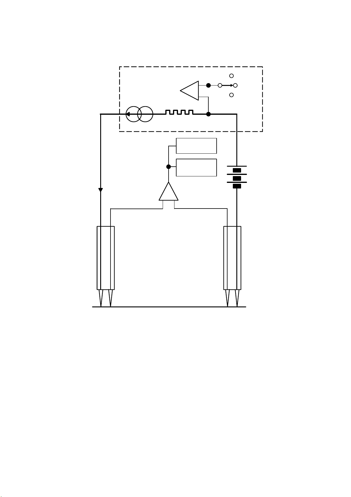
The measurement principle is to circulate a calibrated continued current 0.1A, 1A or
10A between any two points A and B materializing the resistance to measure RX. Then
it proceed to read the potential between these two points, the measured voltage at
terminals of the resistance is proportional to the current passing through, according to
the ohm's law:
U = RI
To realize these measurements the instrument uses:
9 A constant current generator supplied with a 12 V Lithium Polymer battery.
9 Two probes with doubles contacts for the "4 wires" measurement:
• A contact (point) to establish the current in the resistance to measure.
• Another contact (point) to measure the potential difference through an
instrumentation amplifier.
9 A voltmeter allows reading the voltage kept at the amplifier output.
Note: the three measurement currents are: 10 A for the metallic and aluminium parts,
1 A and 0.1 A for the composites materials parts.
UM-30300D-U User manual AX 6000 Page 3 / 54
Page 16
3. GENERAL DIAGRAM
y
Preamble
I measure
Current
generator
Shunt
Voltmeter
Automatic
Instrumentation
amplifier
10 A
1 A
0.1 A
zero
Batter
Probe
RX
A B
Probe
UM-30300D-U User manual AX 6000 Page 4 / 54
Page 17

Preamble
4. AUTOMATIC ZERO
During its measurement cycle, the instrument carried out automatically an auto-zero
measurement to eliminate undesirables' thermo-electrics effects in the measurement
circuit and carried out the measurement zero of the instrument compensating the
offset errors in the measurement amplifier.
Then, at each measurement, the instrument memorizes the spurious external voltage
of the thermocouple present in the R
terminal before the passage of the current in
X
order to subtract it from its new value obtained during the passage of the current.
5. BATTERY / INSTRUMENT AUTONOMY
The 12VDC 4400 mA/h battery with Lithium Polymer (Li-Po) technology is integrated in
a bloc. This technology allows for the best space / electrical capacity. The battery pack
is removable from the device without tools.
The battery capacity guaranteed to carry out 1000 measurements. Following the
battery state, number of charges and its age, it's possible that the number of
measurement will decrease significantly, in this case, change the battery with a new
one and recycle the old one (see the recycling conditions in the appendices).
The battery charge is carried out with the power supply which connected with a jack
connector. The battery is fitted with a light (LED) which indicates to the user the charge
state. The complete charge time is less than 3 hours. The charge can be carried out the
battery out of the instrument.
Use only the power supply fitted with the instrument. See the instructions and security
precautions concerning the instrument use in the appendices.
UM-30300D-U User manual AX 6000 Page 5 / 54
Page 18
6. MEASUREMENT CHARACTERISTIC
Preamble
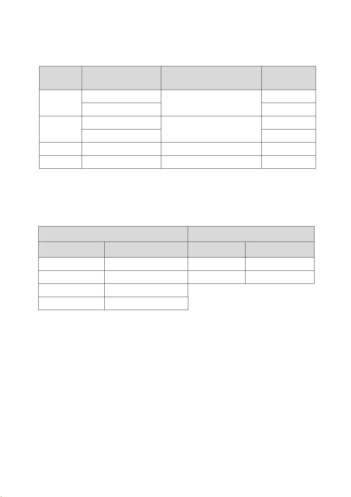
Range
Measurement
Current
Accuracy Resolution
1A 1 µΩ
6 mΩ
10A
+/- (0.1 % MV + 6 µΩ)
1 µΩ
0.1A 100 µΩ
60 mΩ
1A – 10A
+/- (0.1 % MV + 60 µΩ)
10 µΩ
600 mΩ 0.1A – 1A – 10A +/- (0.1 % MV + 0.6 mΩ) 100 µΩ
6 Ω 0.1A – 1A +/- (0.1 % MV + 6 mΩ) 1 mΩ
MV = Measured Value.
6.1. MEASUREMENT RANGES SELECTION
The measurements ranges can de selected automatically (auto-ranging) or manually
by the user, it's the following ones:
Manual mode Automatic mode
Range Current Range Current
6 mΩ (2 mΩ) 1A – 10A (3A) 1µΩ – 600mΩ 10A
60 mΩ (20 mΩ) 0.1A – 1A – 10A (3A) 10µΩ – 6Ω 1A / 0.1A
600 mΩ (200 mΩ) 0.1A – 1A – 10 A (3A)
6 Ω 0.1A – 1A
UM-30300D-U User manual AX 6000 Page 6 / 54
Page 19
1. APPEARANCE
Chapter 1 – Instrument installation
Chapter 1
INSTRUMENT INSTALLATION
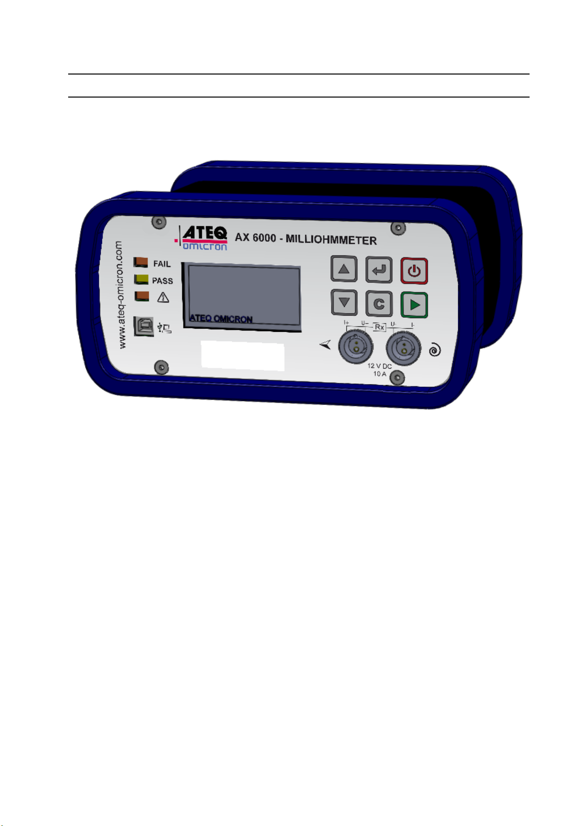
The ATEQ AX6000 case is made with two anodized aluminum parts assuring durability
and lightness. The case is surrounded by two rubbers to protects the device from falls
and avoid marking the shocked part.
UM-30300D-U User manual AX 6000 Page 7 / 54
Page 20
2. INSTRUMENT INSTALLATION
2.1. BATTERY BLOCK / SUPPLY
Chapter 1 – Instrument installation
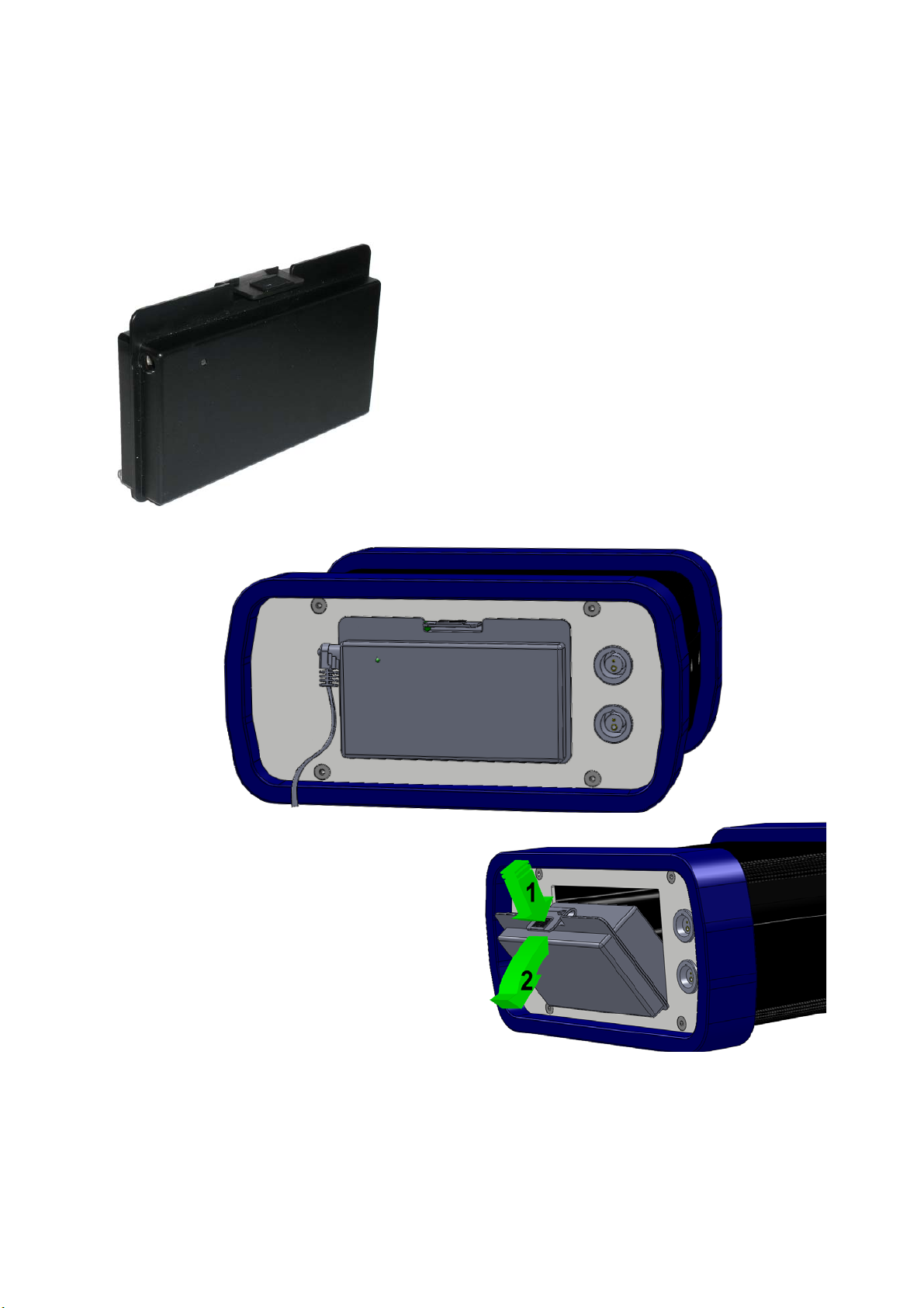
The ATEQ AX6000 is running with a 12 V DC
battery.
The battery has a LED light for charge state:
9 Red: The battery is charging.
9 Green: battery full.
To remove the battery from the device,
proceed as follows:
1) Press the burst above to unlock.
2) Turn the battery outwards.
To reinstall the battery, do the same
operation in the reversal way.
UM-30300D-U User manual AX 6000 Page 8 / 54
Page 21
Chapter 1 – Instrument installation
2.2. ELECTRICS CONNECTORS
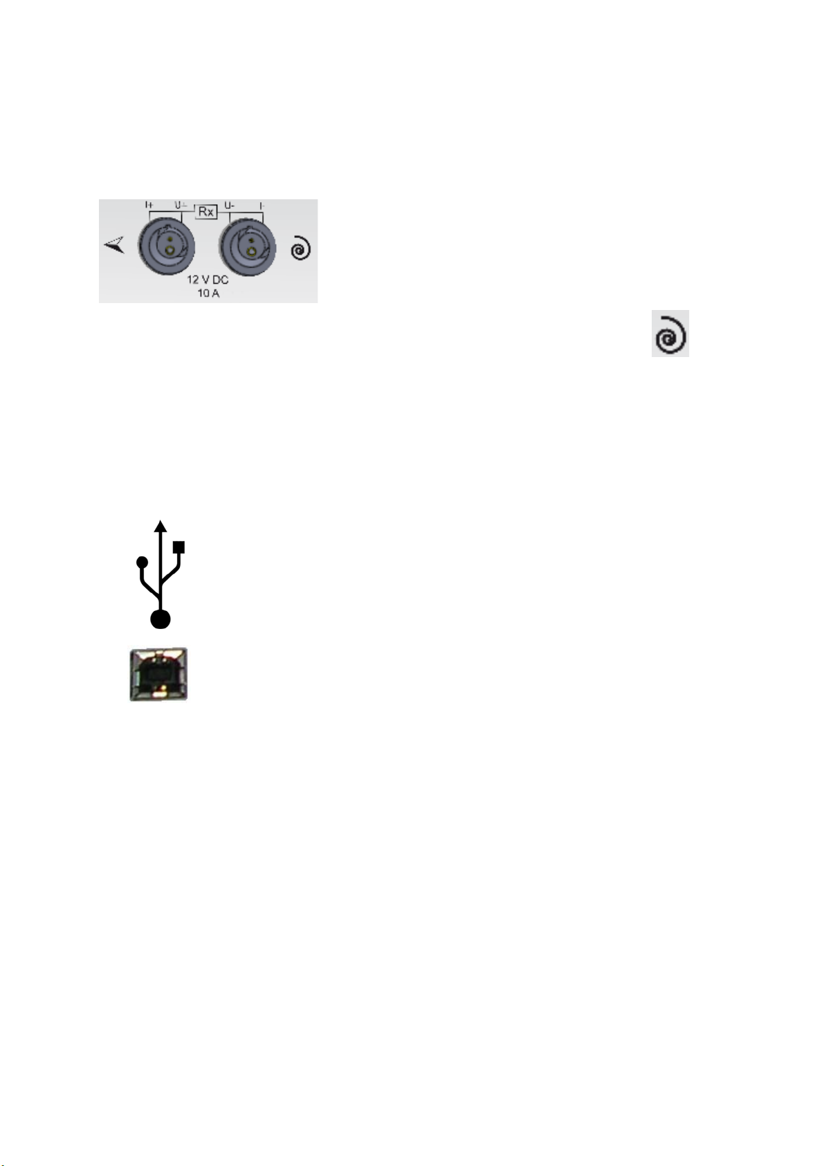
2.2.1. Test accessories connectors
The test accessories, probes, Kelvin probes pliers, etc.
are connected on these two plugs. There are two
connectors on the front face and two on the rear face
that the user will choose following the use.
If a spool of wire is used, it must connect this spool to the plug identified by
.
Note: if a winding is used and if it's partially or not unwound, it's possible that the device
has some measurements problems and displays the "Continuity U fault" message. In
this case, it's strongly advisable to configure the instrument in the "Inductive" mode. See
the chapter 3, paragraph 5.1.6 "Measurements modes".
2.2.2. USB Connector (front and rear faces)
Allows the connection to a PC. Allows the supervision with the
Winateq300 software:
9 Configuring (save / restore the parameters in a PC).
9 Duplicate an instrument.
9 Up dating the device.
9 Results recovery for archiving and statistic analysis with
spreadsheet software's.
See the Winateq300 software manual.
UM-30300D-U User manual AX 6000 Page 9 / 54
Page 22

Chapter 1 – Instrument installation
UM-30300D-U User manual AX 6000 Page 10 / 54
Page 23
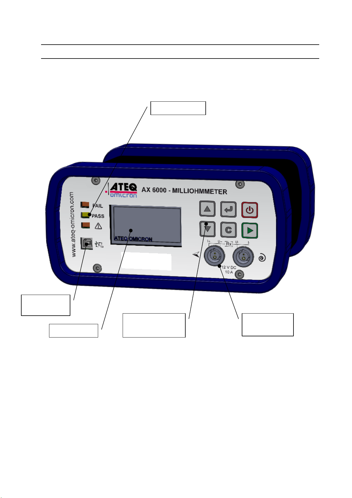
1. PRESENTATION
Chapter 2 – User interfaces
Chapter 2
USER INTERFACES
Results lights
USB
connector
Display
Navigation and
control keys
Tests
connectors
UM-30300D-U User manual AX 6000 Page 11 / 54
Page 24
2. KEYBOARD PRESENTATION
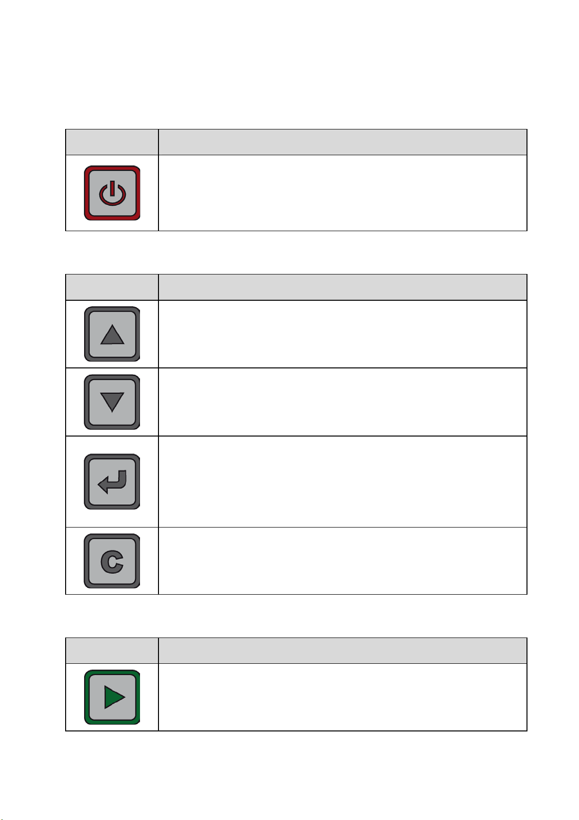
2.1. ON / OFF KEY
KEY FUNCTION
Instrument off: this key switch on the device.
Instrument on: this key switch off the device by long pressing (more
2.2. NAVIGATION KEYS
KEY FUNCTION
Chapter 2 – User interfaces
than 3 seconds).
Move up or increase the numeric values.
Move down or decrease the numeric values.
ENTER key
Quick press: Enter in the special cycle's menu, parameter entering,
parameter validation.
Long press (3 seconds): Enter in the parameters and configuration
menu.
"C" for CANCEL
Return to the previous function or menu.
Escape without parameter's modification.
2.3. START CYCLE KEY
KEY FUNCTION
START key
Starting a measurement cycle.
UM-30300D-U User manual AX 6000 Page 12 / 54
Page 25
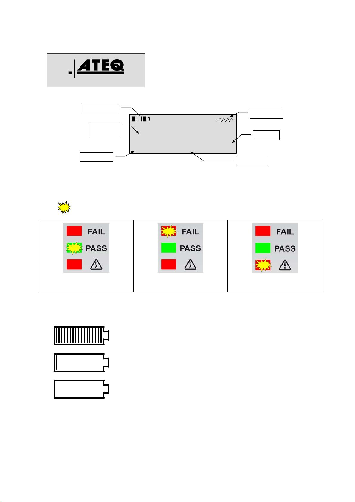
3. LCD DISPLAY
A
P
6
X 6000 V1.11a
Display detail:
Battery level
Test result
Value
To display the measurement results and the
parameters to adjust.
Program 1
1.000 mΩ
Chapter 2 – User interfaces
Test mode
Range
10A
Test current
ASS
4. FUNCTIONS OF THE INDICATOR LIGHTS
The symbol represents an indicator which is lit.
Pass part light. Fail part light. Alarm.
5. BATTERY LEVEL
mΩ
Test result
Battery full.
When the display indicates an almost empty battery level, it is
better to recharge.
Empty battery, recharge it (flashing) the instrument will turn
off.
Note: if the instrument doesn't turn on, before any service in the device, recharge
completely the battery or replace it with a full one.
UM-30300D-U User manual AX 6000 Page 13 / 54
Page 26
Chapter 2 – User interfaces
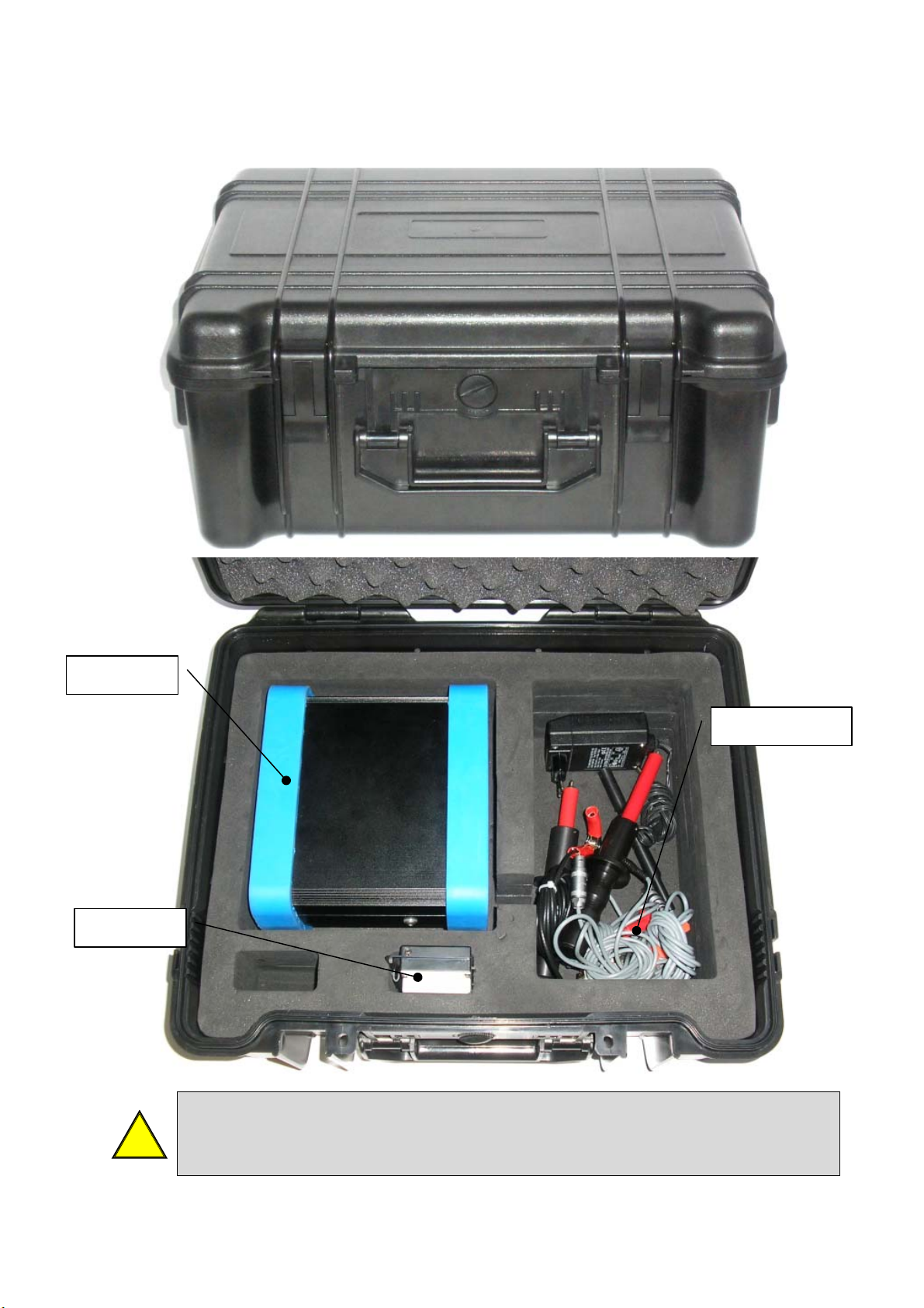
6. CARRYING CASE
Note: The color of the carrying case can change without notice.
AX 6000
Batteries
Accessories
!
UM-30300D-U User manual AX 6000 Page 14 / 54
Important note: do not charge the battery when it installed into the carrying
case, you must remove it to avoid overheating. See the instructions
concerning the battery in the appendices.
Page 27
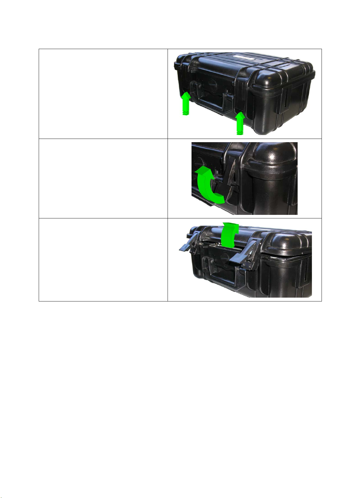
6.1. OPEN THE CARRYING CASE
Push the two buttons at the bottom of
the locks.
The locks will be released.
Lift the two locks to release the cover.
Chapter 2 – User interfaces
Then open the cover to access to the
instrument.
UM-30300D-U User manual AX 6000 Page 15 / 54
Page 28
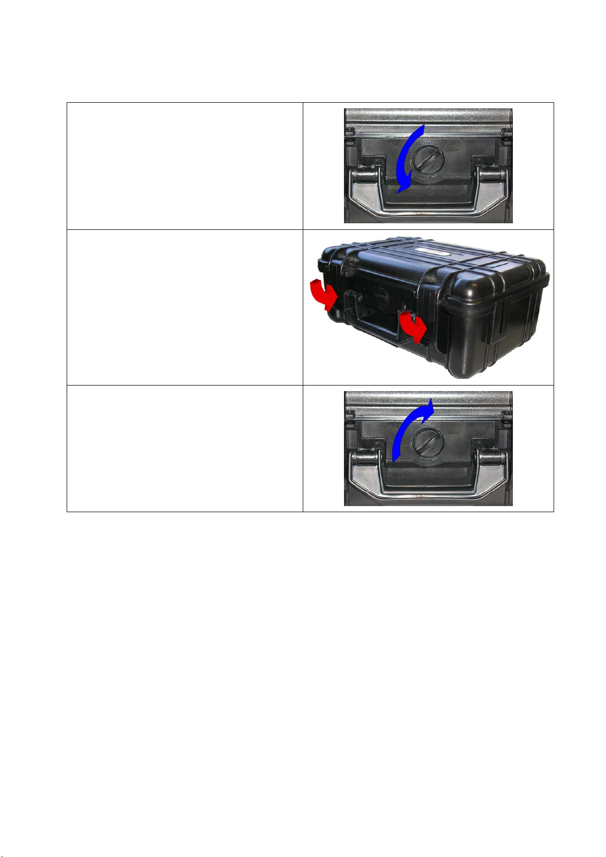
6.2. CLOSE THE CARRYING CASE
Before closing the housing box, open the
purge button (left turn).
Close the cover and lock the two locks.
Chapter 2 – User interfaces
Then close the purge button (right turn)
to complete the sealing.
UM-30300D-U User manual AX 6000 Page 16 / 54
Page 29
Chapter 3 – Starting up and adjustments
AX
6000
V
3.0
2
Chapter 3
STARTING UP AND ADJUSTMENTS
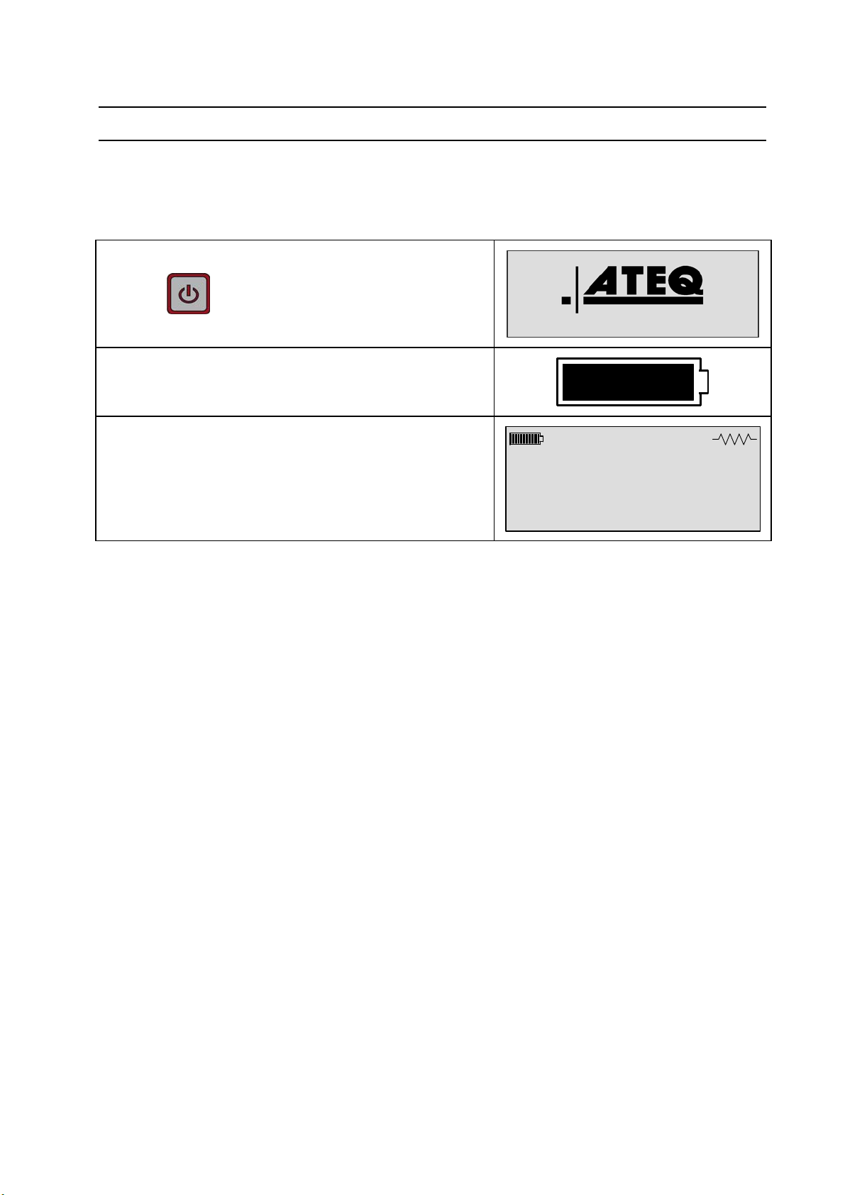
1. TURN ON THE DEVICE
The AX6000 is running with its integrated battery.
Switches on the instrument.
Check the battery level.
Program 1
The instrument waits a start.
10A Auto
Note: if the device doesn't turn on, charge completely the battery or replace it with a full
one.
UM-30300D-U User manual AX 6000 Page 17 / 54
Page 30
Chapter 3 – Starting up and adjustments
MAIN
MENU
PASSWORD MODE
LOCK
PARAMETERS
MAIN
MENU
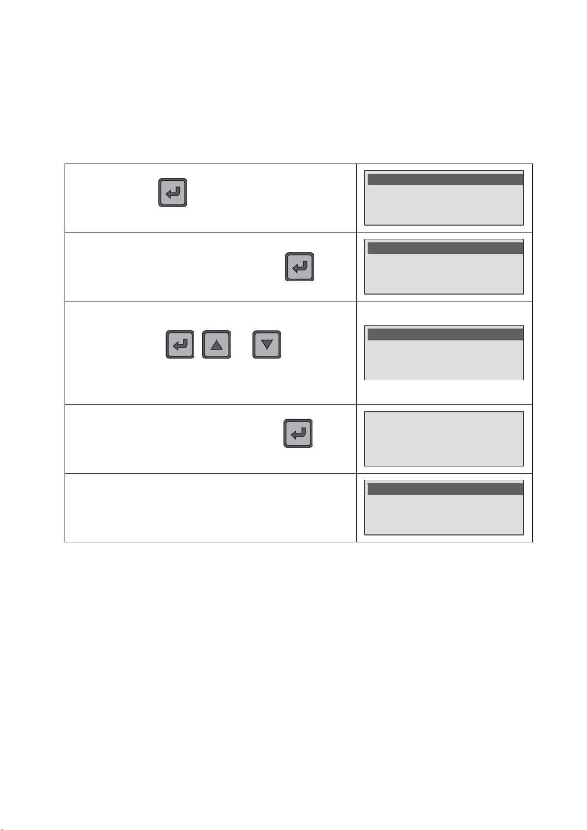
2. LOCK / UNLOCK
This function allows locking the test parameters access; this to avoid any hazardous
parameters modification. The password by default is 0000.
2.1. LOCK OPERATION
Press and hold the key (three seconds) to enter into the
main menu and select the Parameters : Unlock function.
Choose the Lock mode and validate with the key.
For the first time (no password entered) the instrument asks to
enter one, enter 4 numbers (replace 0000 with your personal
code) by using the
Note: once the password is entered, the instrument won't
require it for the next locks.
When the password is entered, validate with the key, the
instrument displays: Parameters Locked.
, and keys several
times.
>Parameters: Unlock
Mode : Program
Program : Pr01
>Lock
>Password : 0000
Parameters Locked
To lock the parameters access, select the Parameters : Lock
function.
>Parameters: Lock
Mode : Program
Program : Pr01
UM-30300D-U User manual AX 6000 Page 18 / 54
Page 31
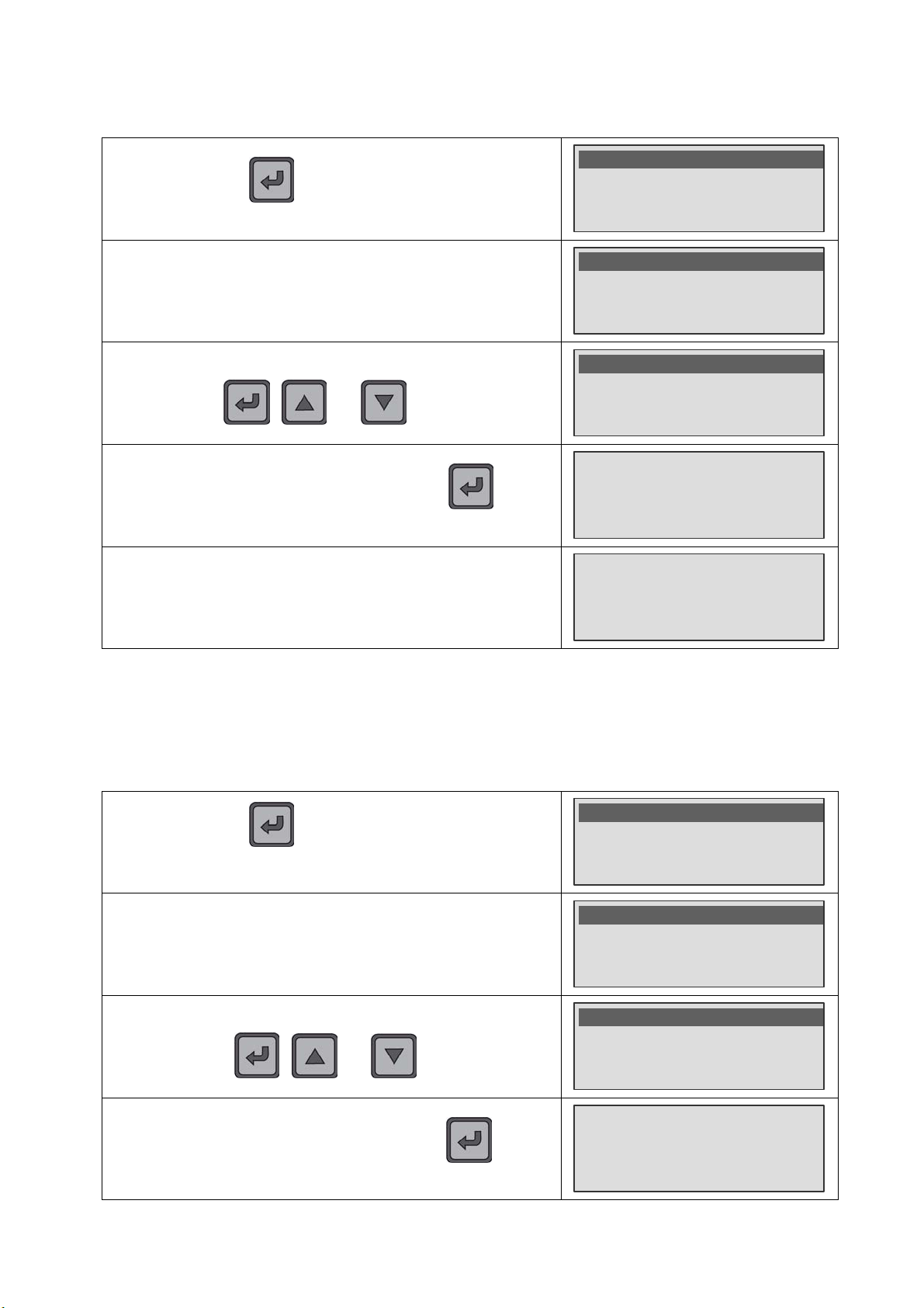
2.2. UNLOCK OPERATION
MAIN
MENU
PASSWORD MODE
LOCK
PARAMETERS
MAIN
MENU
PASSWORD MODE
ERASE PASSWORD
Chapter 3 – Starting up and adjustments
Press and hold the key (three seconds) to enter into the
main menu, select the Parameters : Lock function.
To unlock the parameters access, select the Unlock function.
The instrument asks the password, enter the 4 numbers by
using the
When the password is entered, validate with the key the
message Parameters Unlocked appears.
If the password is incorrect, the message Password error is
, and several times.
displayed.
>Parameters: Lock
Mode : Program
Program : Pr01
>Unlock
Erase
>Password : 0000
Parameters Unlocked
Password Error
2.3. PASSWORD ERASE
The deletion of the password of the Lock / Unlock function needs to know the current
password. After deletion, the current password becomes the password by default
(0000).
Press and hold the key (three seconds) to enter into the
main menu, select the Parameters : Lock or
Parameters : Unlock function.
To delete the password, select the Erase function.
>Parameters: Unlock
Mode : Program
Program : Pr01
Unlock
>Erase
The instrument asks the current password, enter the 4 numbers
by using the
, and several times.
>Password : 0000
When the password is entered, validate with the key, the
UM-30300D-U User manual AX 6000 Page 19 / 54
Password Erased
instrument displays Password Erased.
Page 32
Chapter 3 – Starting up and adjustments
MAIN
MENU
PROGRAMS
LIST
3. MODE FUNCTION
The instrument had two test modes, the Program mode and the Sequence mode.
The Program mode allows running programs individually and unitary. The program to
run choice is made by the user. The programs can be created from the front face of the
device or from the Winateq300 software. 128 different programs can be created.
The Sequence mode allows chaining several programs ones after ones following a
defined order. The sequence choice is made by the user. One program can be in
several different sequences and can be several times into the same sequence. The
sequences can be edited only from a PC fitted with the Winateq300 software.
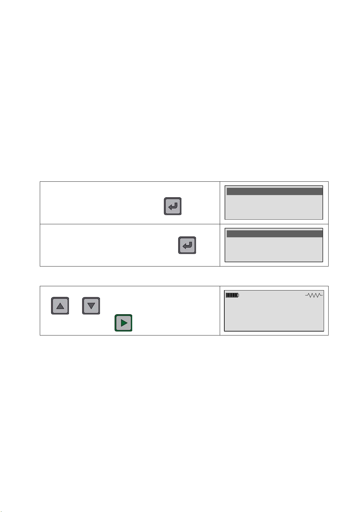
3.1. PROGRAM NUMBER CHOICE
3.1.1. Main menu mode
In the main menu, put the cursor in front of Program to select
the program to run, validate with the
Select the program to run and validate with the key.
key.
3.1.2. Cycle mode
To select the program to run in the CYCLE mode, use the
and keys, then run the test program with the
key.
Parameters: Unlock
Mode : Program
>Program : Pr01
PR01
>PR02
PR03
Program 1
10A Auto
UM-30300D-U User manual AX 6000 Page 20 / 54
Page 33

4. TEST PROGRAM CREATION
MAIN
MENU
MAIN
MENU
MAIN
MENU
MAIN
MENU
MAIN
MENU
Chapter 3 – Starting up and adjustments
Press and hold the key (three seconds) to enter into the
main menu.
In the main menu, put the cursor in front of Program to select
the program to edit and validate with the
Select the program to editing then validate with the key.
By using the key, go to the NAME parameter and
validate with the
Enter the name by using the , and keys
several times, when the name is entered, validate with the
key.
key.
key.
>Parameters : Unlock
Mode : Program
Program : Pr01
Parameters : Unlock
Mode : Program
>Program : Pr01
PROGRAMS LIST
PR01
>PR02
PR03
Mode : Program
Program : Pr02
>Name :
Mode : Program
Program : Pr02
>Name : WING™
The program is created and the test parameters can be entered.
The test parameters appear after the menu.
Program : Pr02
>Name : WING L
Current : 10A
UM-30300D-U User manual AX 6000 Page 21 / 54
Page 34
Chapter 3 – Starting up and adjustments
MAIN
MENU
MAIN
MENU
MAIN
MENU
MAIN
MENU
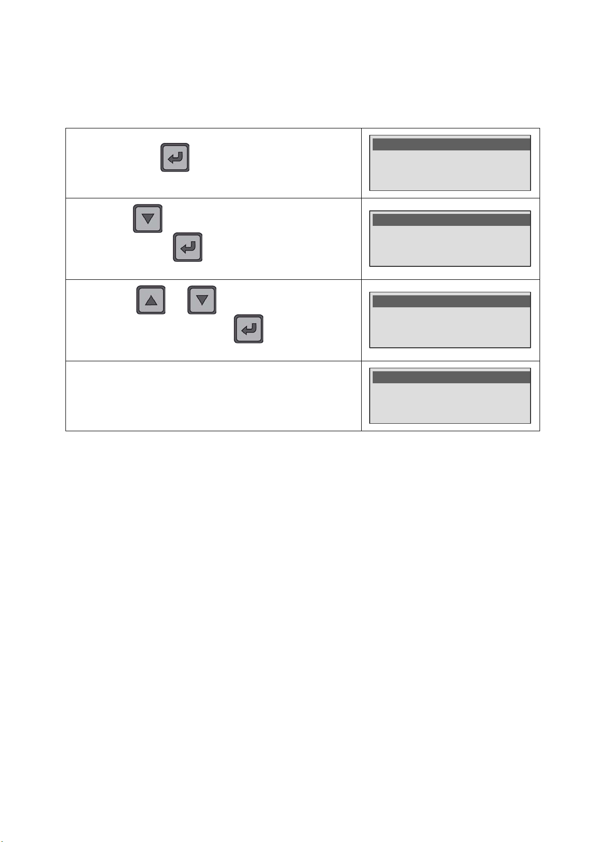
5. PARAMETERS ADJUST
Now adjust the test cycle parameters.
The process to adjust the parameters is the same for all.
Press and hold the key (three seconds) to enter into the
main menu.
By using the key, move down up to the test parameters
and validate with the
side to confirm the parameter edition.
By using the and keys, adjust the parameter to
the hope value and validate with the
to the left side of the display.
Adjust the others parameters by using the same process.
key, the cursor goes on the right
key, the cursor back
Parameters : Unlock
Mode : Program
>Program : Pr01
Name : WING L
Current : 10A
>R Max : 1.000mΩ
Name : WING L
Current : 10A
R Max : 1.300m
Name : WING L
Curreant : 10A
>R Max : 1.300m
Ω <
Ω
5.1. PARAMETERS TO ADJUST
5.1.1. Program name (NAME)
This function allows personalizing a program, for example to identify it with the part to
test name. Enter 7 alphanumeric characters maximum.
5.1.2. Measurement current (CURRENT)
The instrument had three measurements current available, the value to use is based on
the material of the parts to control:
¾ 10 A for the metallic parts,
¾ 1 A and 0.1 A for the composites material parts.
5.1.3. Maximum reject (R Max.)
This parameter defines the threshold above the test part is considered as fail. If the
measured value exceeds this value, the test is fail.
UM-30300D-U User manual AX 6000 Page 22 / 54
Page 35
Chapter 3 – Starting up and adjustments
5.1.4. Minimum reject (R Min)
This parameter defines the threshold below which the test part is considered as fail. If
the measured value does not exceed this value, the test is fail.
Note: the measurement result must be between the minimum reject and the maximum
reject to be declared pass, if not the test will be fail.
5.1.5. Measurement ranges
The measurements ranges allow define the measurement size. More the range size is
small; more the measurement will be fine and precise.
The measurement ranges can be selected automatically (auto-ranging) or manually by
the user.
The ranges are: Auto, 6Ω, 600 mΩ, 60mΩ, 6mΩ (200 mΩ, 20mΩ, 2mΩ for the 3A
current option).
The ranges measurement values and their accuracy are indicated in the preamble of
this user manual.
The manual mode allows to directly target the range which the user is waiting the
measurement result. If he didn't know the range which the measure may be carried out,
it's better to select the "Auto" mode, the instrument will apply the most appropriate
range.
Note: in automatic mode, the test time is a little longer than the manual mode (range
research) so, the total number of tests for a battery charge can be less.
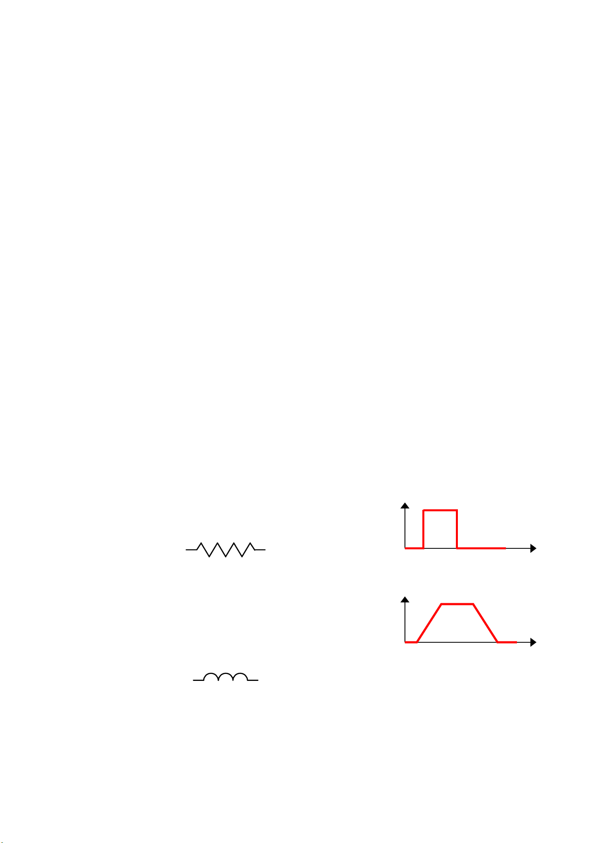
5.1.6. Measurement mode
The current establishment can be done following the two modes. The mode is
represented by a symbol in the upper right corner of the display in test mode.
I
Resistive mode: the current establishment is
instantaneous. The resistive mode is represented by:
Inductive mode: to limit the impact due to inductive
elements (coils) present in the measuring circuit (case of
a 100 m winding not unwind or partially unwind)
This mode generates a progressive test current rise and
drop in the measurement circuit. The rise and drop times
can't be modify. The inductive mode is represented by:
t
I
t
UM-30300D-U User manual AX 6000 Page 23 / 54
Page 36

Chapter 3 – Starting up and adjustments
A
A
Automatic mode: this mode allows detecting if the circuit is inductive or resistive.
Following the characteristics of the measured circuit, the device will adapt its
measurement. The icon displayed on the right top of the screen show the mode.
If the circuit is resistive, the device displays the symbol:
If the circuit is inductive, the device displays the symbol:
Note: in the case of installation of a reel on the measurement circuit, it will be
automatically detected in this mode
5.1.7. Pass part chaining
This function appears only in "Sequence" mode. It allows shifting automatically to the
next step of the sequence, if the measurement of the current step is declared pass.
MAIN MENU
Validate by "On" the "Chaining PP" function, when the
measure of the step is pass, the device shift automatically to
the next step.
5.1.8. Serial Number 2
Mode : Automatic
>Chaining PP : On
SYSTEM SETTINGS
This parameter is available only with Winateq300 software. It allows distinguishing
devices. This serial number will appear in the frame of the results file.
UM-30300D-U User manual AX 6000 Page 24 / 54
Page 37
Chapter 3 – Starting up and adjustments
P
6
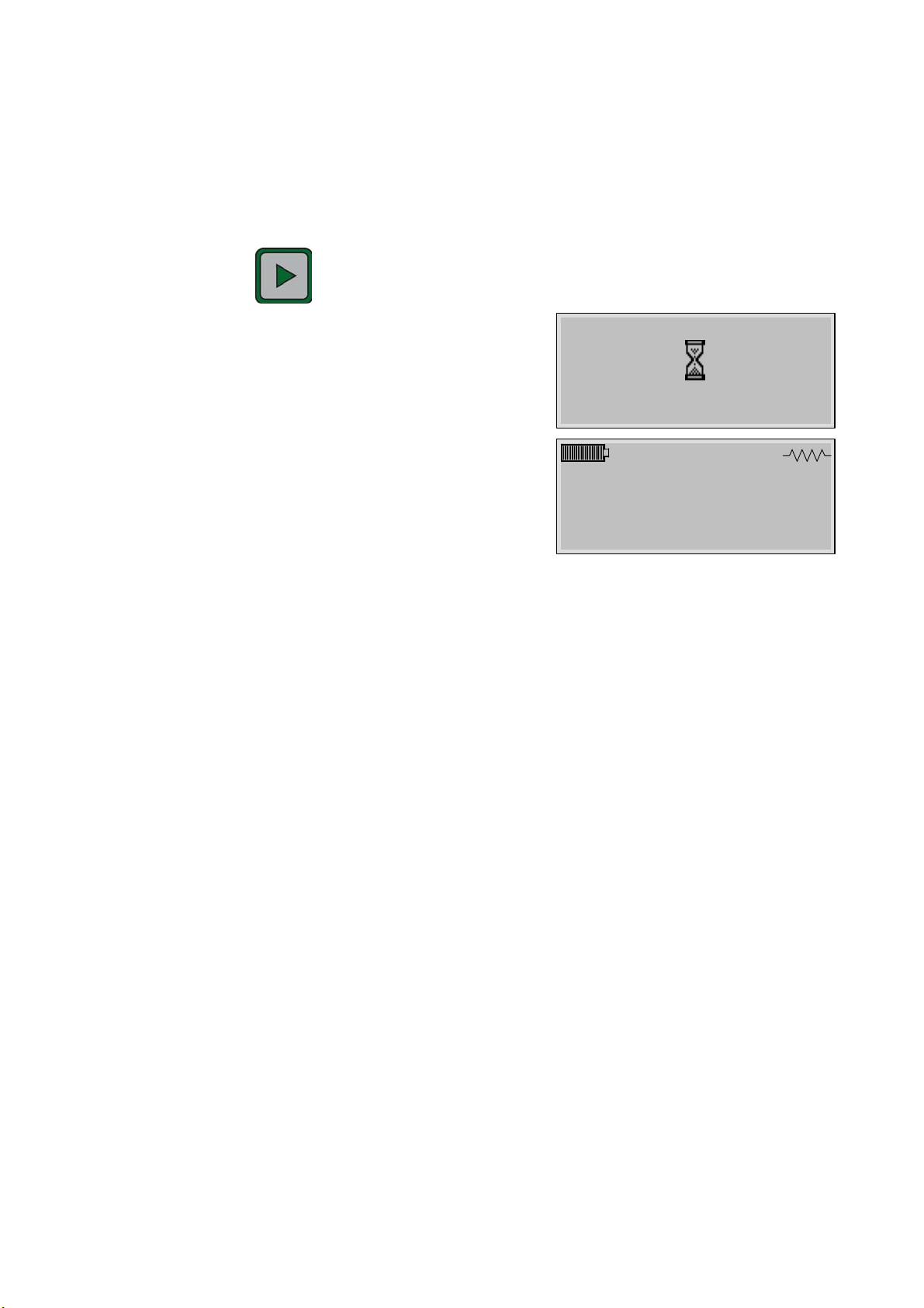
6. MEASUREMENT TRIGGERING
The measurement is triggered by:
¾ Simple accessories contact on the part to test (current detection). If the
Auto Start function is on.
¾ Press the key on the instrument front face.
During the measurement, an hourglass is
displayed.
Note: if the Buzzer function is validate, a beep is
ringing during the test time.
The test stops and the measurement result is
displayed.
1.002 mΩ
10A
Note: if the device detects a fail part or an alarm, when the Buzzer function is activated,
a series of short beeps are ringing.
6.1. AUTO-TEST
The instrument is fitted with an auto-test (internal test) to check the test current value.
This test is carried out with a precision resistance integrated within the instrument.
PLEASE WAIT
Program 1
ASS
mΩ
7. TEST STOP
The resistance measurement stops by:
¾ A contact cut from one of the probes (current passing cut).
¾ Automatically at the end of the test.
7.1. MEASUREMENT FAIL DETECTION
An error message notifies the operator for all fail values recorded due to cuts in one of
the two loops of the measuring circuit during the test (rebounds contacts, probes press
too low, etc.).
UM-30300D-U User manual AX 6000 Page 25 / 54
Page 38
Chapter 3 – Starting up and adjustments
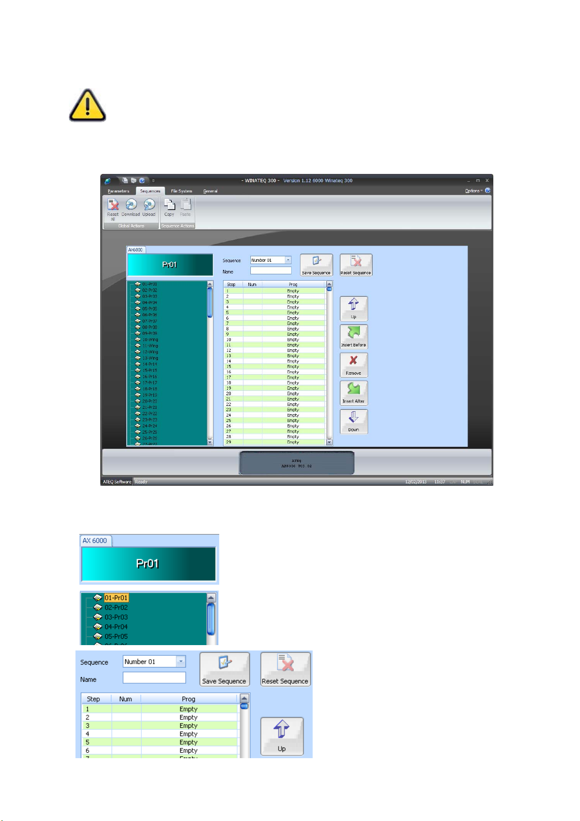
8. SEQUENCES CONFIGURATION (WINATEQ300/AX)
The sequences configuration can be done only with the Winateq300 6000
software.
The sequence mode allows chaining several programs the ones after the others
following a defined order that the operator may follow. Maximum characteristics: 128
programs; 32 sequences; 999 steps programs in a sequence.
8.1. WINDOW DETAILS
Name of the device connected (left up) and number of
the selected program or its name if existing.
Display window of the programs list.
Display window of the selected
sequence.
UM-30300D-U User manual AX 6000 Page 26 / 54
Page 39
Chapter 3 – Starting up and adjustments
8.2. AVAILABLE COMMANDS DETAIL
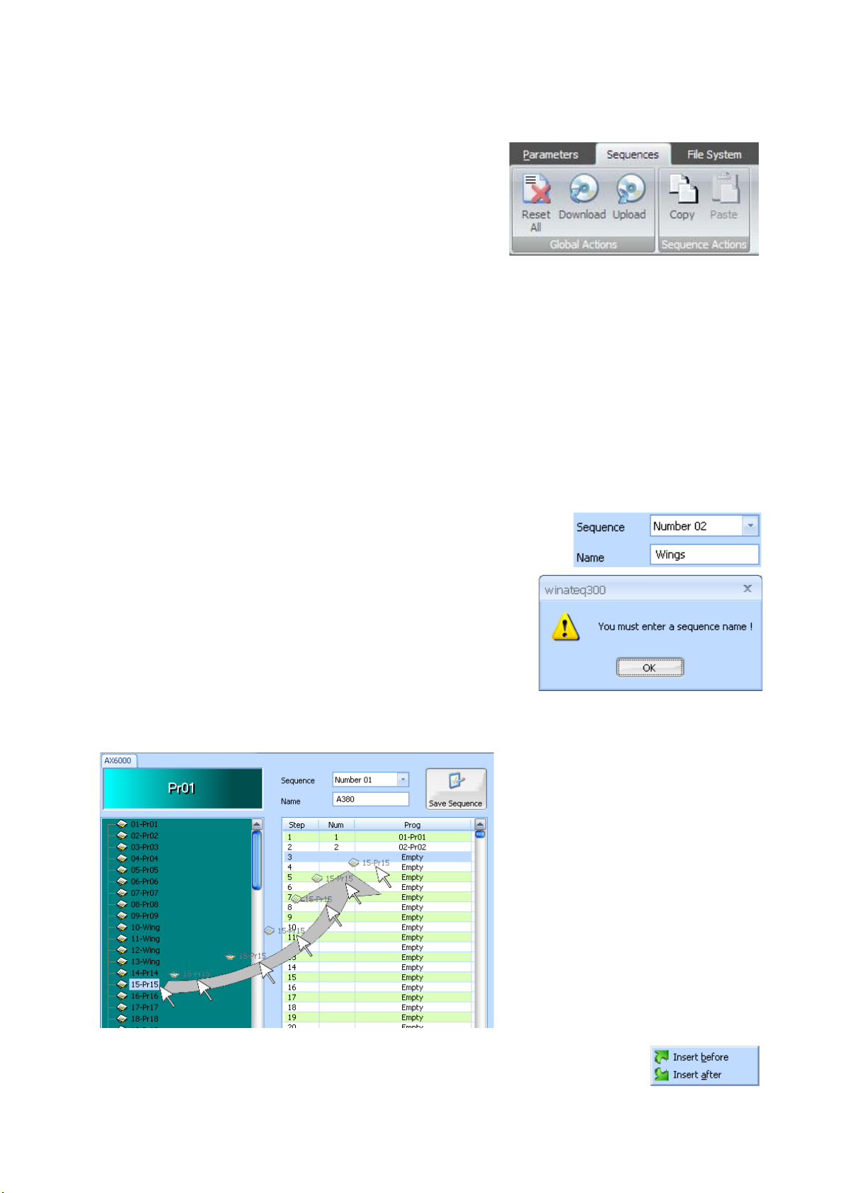
Global Actions menu:
9 Reset All: deletes all the sequences in the
device.
9 Download: to save on the PC hard drive all
the sequences ("Sequences.seq" files).
9 Upload: to restore from the PC hard drive the sequences ("Sequences.seq"
files).
Sequences Actions menu:
9 Allows to Copy a sequence in the clip board.
9 Allows to Paste the sequence from the clip board.
8.3. SEQUENCE MANAGEMENT
8.3.1. Sequence creation
Select the sequence to create among the 128 available.
Do not forget to give a name for the sequence (the
software will remind you).
8.3.2. Program insertion
First solution: to insert a
program in the sequence, do a
"Drag/Drop": With the mouse,
drag a program you want in the
left window and drop it in the
sequence window (right) at the
position you want.
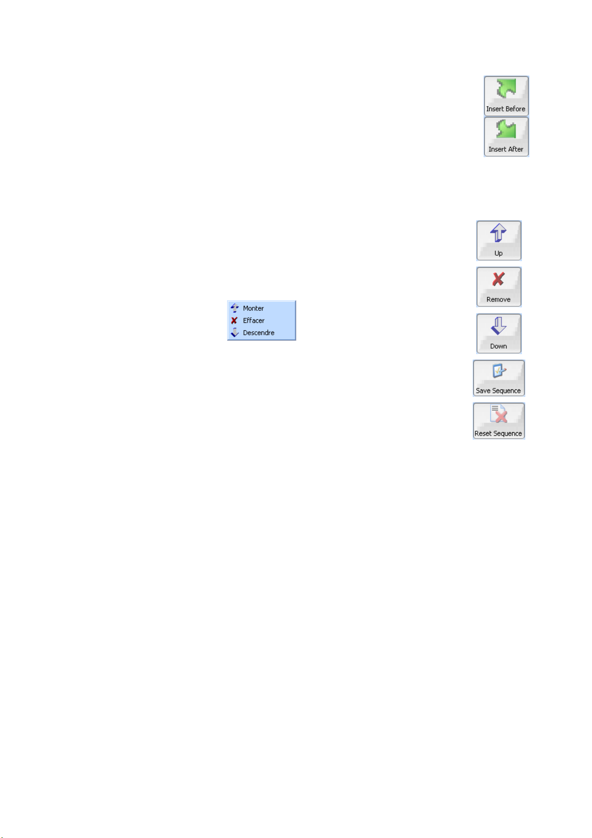
Second solution: select a program, do a "right click", the menu
appears asking insertion position in the sequence (Insert before or
Insert after).
UM-30300D-U User manual AX 6000 Page 27 / 54
Page 40
Chapter 3 – Starting up and adjustments
Insert Before: to insert the program above the selected step.
Insert After: to insert the program below the selected step.
8.3.3. Sequence management
The "Up", "Remove" and "Down" keys allows moving the programs in
the sequence.
These actions are also available with a "right click" in the sequence
window.
Once the sequence is created, it must download it into the device, use
the "Save Sequence" key.
To completely delete the sequence, press the "Reset Sequence" key,
the device will prompt you a confirmation.
UM-30300D-U User manual AX 6000 Page 28 / 54
Page 41
Chapter 3 – Starting up and adjustments
MAIN
MENU
SYSTEM SETTINGS
MENU
MODE
SYSTEM SETTINGS
MENU
SYSTEM SETTINGS
MENU
MODE
9. SEQUENCE MODE RUNNING
The sequence mode allows chaining several programs the ones after the others
following a defined order. Each program is a step. The sequences can contain until 999
steps. A test program can be several times in the same sequence, or in several
sequences.
The tests cycles are chained according the user who will run the steps whatever the
result of each test (pass part or fail part).
Remind: The sequences programming can only be done from the Winateq300
software. See paragraph 8 "Sequences configuration (Winateq300/AX)".
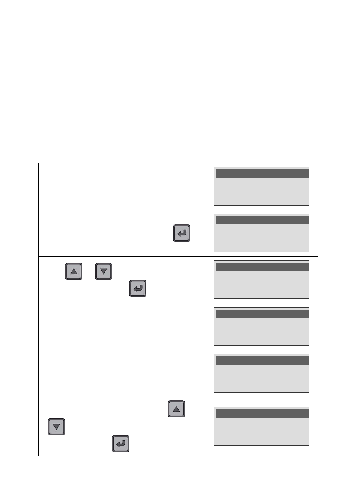
9.1. "SEQUENCE" MODE SETTING
Access to the menu des "SYSTEME SETTINGS" menu to
validate the sequence mode.
Select the "Mode" parameter and validate with the key.
With the and keys select the "Sequence" mode,
validate with the
The device confirms the "Sequence" mode selection.
key.
Range : Auto
Mode : Resistive
>SYSTEM SETTINGS
>Mode : Program
Language : English
Date : 04/02/2013
Program
>Sequence
>Mode : Sequence
Chaining PP : Off
Language : English
Once the "Sequence" mode selected, the parameter
"Chaining PP" appears. This parameter, when validated by
"On", allows shift to the following step in the sequence when
To back to the "Program" mode, by using the
key, select the "Program" mode, and validate with
UM-30300D-U User manual AX 6000 Page 29 / 54
the current test is "Pass".
.
and
Mode : Sequence
>Chaining PP : On
Language : English
>Program
Sequence
Page 42
Chapter 3 – Starting up and adjustments
OPERATO
R
1A
TO DO Aut
1A
TO DO Aut
10
0mA
PASS
Aut
1A
TO DO Aut
10
0mA
PASS
Aut
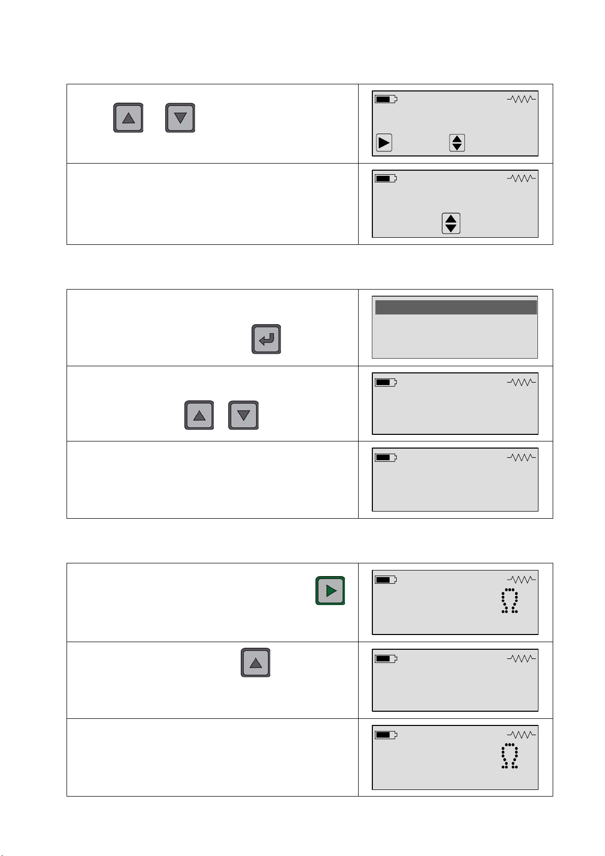
9.2. SEQUENCE SELECTION
With the and keys, select the sequence to carry
out (here S01). We access the "Operator" menu (see below).
If the sequence doesn't exist, the message
"Empty sequence" appears on the screen. Back to a
available sequence.
9.3. OPERATOR NAME INPUT
S01
"Wings"
Start
S09
Empty sequence
Seq. +/-
Seq.+/-
When the "Operator" menu appears, enter or check the
operator name, this name will appear in the results frame.
Then select "Validation" and press the
The device will wait for measuring the first step; it displays the
program and the step. It's possible to change the step by
using the
If the fields "Name", "N2" and "N3" are filled, they will appear
or keys.
here.
key to validate.
9.4. CARRYING OUT THE MEASUREMENT OF A SEQUENCE
Make a contact with the probes and press again the
key. If the Auto Start function is on, the device runs a
measurement automatically.
>Name : JACK
Validation
Program 1
Step : 1/2
Wing
Left
Intern
Program 1
0.221m
o
o
o
To jump to the following step, press the key. The message
Program 2
Step : 2/2
"TO DO" appears. Run the second step like the first one. If the
"Chaining PP" option is validate (see above) the steps shift
automatically.
Program 2
So continue with all the steps until the sequence end.
UM-30300D-U User manual AX 6000 Page 30 / 54
0.136m
o
o
Page 43
Chapter 3 – Starting up and adjustments
TO DO
TEST
CANCEL
TEST
NOTAPPLICABLE
TEST
SPECIA
L CYCLES
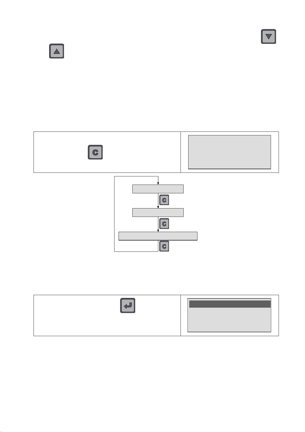
Note: the user can at any time navigate through the sequence by pressing the
and keys. So, he can see the measurement values for each step and see the
remains steps.
9.5. CHANGE A STEP ATTRIBUTE
The user can "jump" a step and leave it "TO DO" or change its attribute:
¾ Attribute "CANCEL" for impossible test.
¾ Attribute "N/A", not applicable for not still installed option.
At any time the step attribute can be change.
To change the step attribute, the user have to press
CANCEL TEST
successively the
"CANCEL TEST" attribute appears.
Note: if the device is turned off during a sequence progress, the sequence will be saved
to be restart when turn on.
9.6. SEQUENCE VALIDATION AND COMPLETION
key. The message with the
By using these functions, it's possible to select:
UM-30300D-U User manual AX 6000 Page 31 / 54
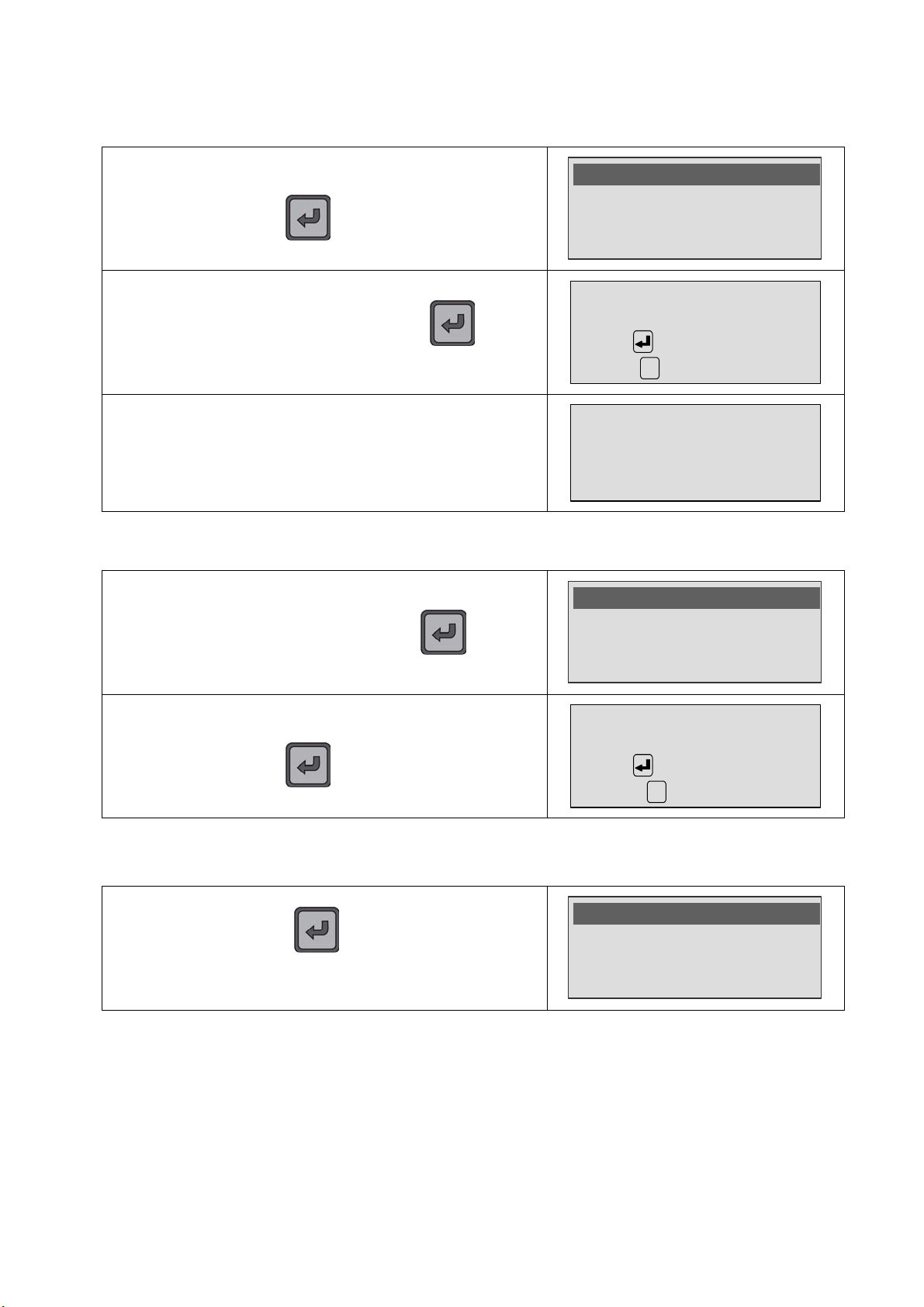
At any time, if the user press the key during the
>Seq. validation
sequence progress, the special cycles menu appears to
manage the sequence.
¾ Seq. validation: to validate and save the current sequence.
¾ Seq. cancellation: to cancel the current sequence, that is to say all the tests
carried out in the sequence and start from the beginning.
Seq. cancellation
Tests -TO DO-
Page 44
9.6.1. Sequence validation
SPECIA
L CYCLES
C
SPECIA
L CYCLES
C
SPECIA
L CYCLES
Chapter 3 – Starting up and adjustments
Select the "Seq. validation" menu to record it and press the
key.
The validation menu is displayed, press the key to
confirm.
When this message appears the sequence is saved. The
steps not carried out won't appear in the results.
9.6.2. Sequence cancellation
To cancel the current sequence, select the
"Seq. cancellation" menu and press the
confirm.
key to
>Seq. validation
Seq. cancellation
Tests -TO DO-
VALIDATION
SEQUENCE
Confirm
Return
SEQUENCE SAUVEE
Seq. validation
>Seq. cancellation
Tests -TO DO-
The device prompt you to confirm the cancellation, press the
key.
CANCELLATION
SEQUENCE
Confirm
Abort
9.7. DISPLAY AGE THE SEQUENCES FILTERS
If the user presses the key during the sequence
progress the special cycle's menu appears to manage the
sequence.
>Tests -TO DO Tests -CANCEL Tests -N/A-
With these functions, it's possible to:
¾ Tests –TO DO-: to display all the steps remaining in the sequence (or the
skipped ones) to ease these steps to retrieve.
¾ Tests –CANCEL-: to display all the steps which are be cancelled in the
sequence to ease these steps to retrieve.
¾ Tests -N/A- : to display all the steps which are be reported "Not applicable".
UM-30300D-U User manual AX 6000 Page 32 / 54
Page 45
FUNCTIONS OF THE INSTRUMENT
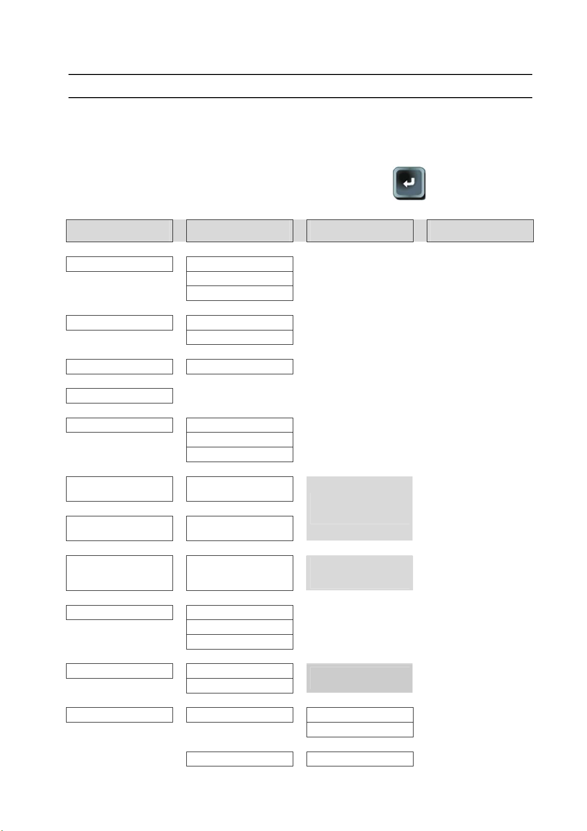
1. MENU STRUCTURE
1.1. MAIN MENU
Chapter 4 – Functions of the instrument
Chapter 4
To access to the main menu, press and hold the ENTER
key until the main
menu appears (about 3 seconds).
MAIN MENU Under menu 1 Under menu 2 Under menu 3
Parameters
V
V
V
MODE
V
V
PROGRAM
V
NAME
V
Current
V
V
V
Maximum reject
(R. MAX.)
V
Minimum reject
(R. MIN.)
V
Measurement ranges
V
MODE
V
V
V
Chaining PP
V
V
System settings
> Unlock
Lock
Erase (password)
> program
Sequence
> Pr 01 to Pr 128
> 10A
1A
100mA
> 0 to 6000mΩ
The maximum thresholds
> 0 to 6000mΩ
Auto > 6Ω > 600mΩ
(200mΩ) > 60mΩ
>
(20mΩ)> 6mΩ (2mΩ)
> Resistive
Inductive
Automatic
> Off
On
> Language > English
V French
V
Date / Hour > No
values can vary following
the chosen range.
The 200mΩ, 20mΩ and
2mΩ ranges are only for the
3A current option.
This menu appears only in
"sequence" mode
UM-30300D-U User manual AX 6000 Page 33 / 54
Page 46
Chapter 4 – Functions of the instrument
MAIN MENU Under menu 1 Under menu 2 Under menu 3
V Yes >
V
V
V
V
V
Backlight > 0% to 100% (step 10%)
V
Auto off > No to 30 min
V
Buzzer > On / Off
V
Automatic Start > On / Off
V
Delete current program
Delete all the programs
Day
Month
Year
Hour
Minutes
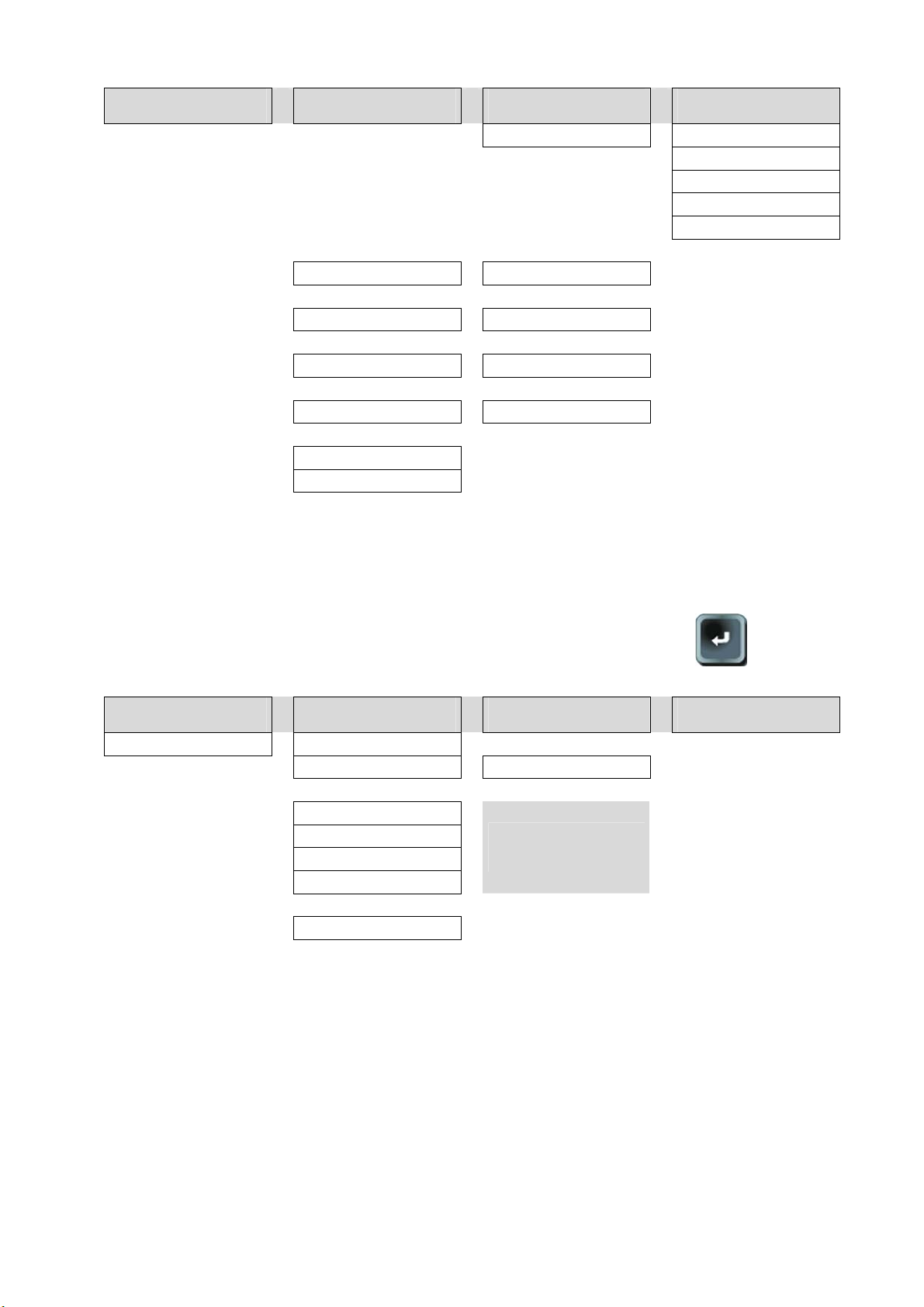
1.2. SPECIAL CYCLES MENU
To access to the special cycles menu, press briefly the ENTER
than one second).
MAIN MENU Under menu 1 Under menu 2 Under menu 3
SPECIAL CYCLE
> None
Auto-test > 10A (3A) > 1A > 0.1A
V
Reset sequence
Tests – TO DO-
Tests –CANCEL-
Tests –N/A-
V
Erase results
These messages appear
only in Sequence mode and
sequence started.
key (less
UM-30300D-U User manual AX 6000 Page 34 / 54
Page 47
Chapter 4 – Functions of the instrument
MAIN
MENU
SYSTEM SETTINGS
MENU
LANG
UAGE LIST
MENU REGLAGES SYSTEME
2. SYSTEM SETTINGS
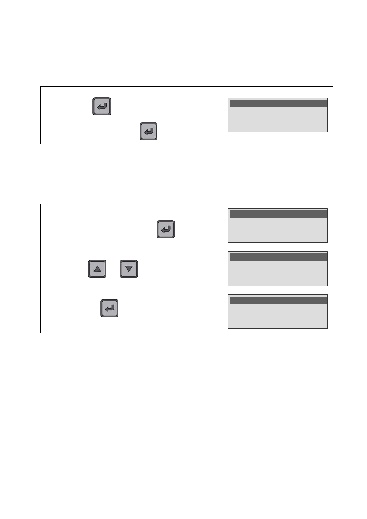
The SYSTEM SETTINGS menu allows configuring the instrument following the user
preferences.
In all cases, to access to the SYSTEM SETTINGS menu, Press
and hold the
MAIN MENU and select the SYSTEM SETTINGS menu.
key (three seconds) to enter to the
Validate with the
key.
Range : Auto
Mode : Resistive
>SYSTEM SETTINGS
2.1. LANGUAGE
This function allows choosing the language displayed. The resident languages in the
device are: English and French.
In the SYSTEM SETTINGS menu, select the Language
function and validate with the
By using the and keys, select the language.
Validate with the key to confirm the new displayed
language.
key.
>Language : English
Date : 10/08/09
Hour : 10:25
>English
French
>Langue : Français
Date : 10/08/09
Heure : 10:25
UM-30300D-U User manual AX 6000 Page 35 / 54
Page 48
Chapter 4 – Functions of the instrument
SYSTEM SETTINGS
MENU
SYSTEM
SETTINGS
MENU
SYSTEM
SETTINGS
MENU
SYSTEM
SETTINGS
MENU
SYSTEM
SETTINGS
MENU
2.2. DATE AND HOUR
The device gets a clock (hour, minutes) and an internal calendar (day, month, year)
which allows dating the events and the archives.
2.2.1. Date
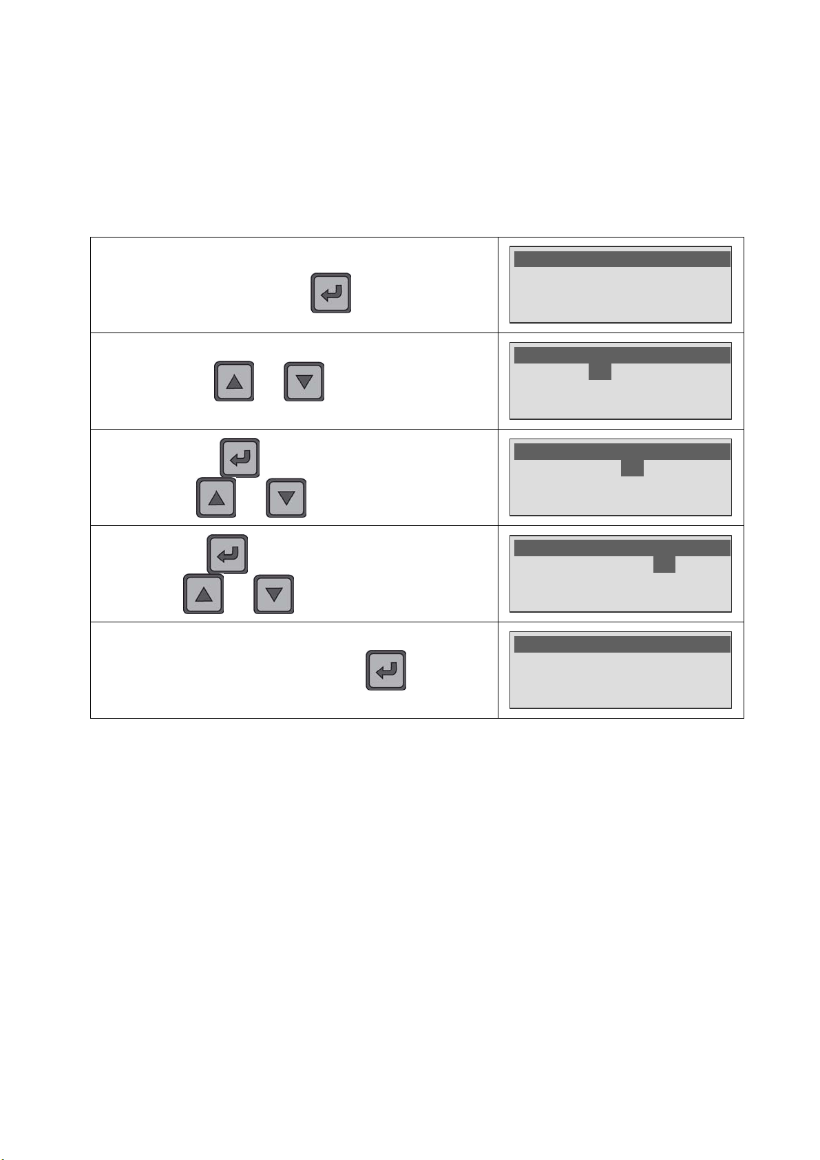
In the SYSTEM SETTINGS menu, select the Date function and
validate with the
By using the and keys, adjust the day.
Validate with the key to skip to the month adjust. By
using the
Validate with the key to skip to the year adjust. By using
the
To save the date, validate with the key.
and keys, adjust the month.
and keys, adjust the year.
key.
Language : English
>Date : 10/08/09
Hour : 10:25
Date : 10/08/09
Hour : 10:25
Backlight : 60%
Date : 10/08/09
Hour : 10:25
Backlight : 60%
Date : 10/08/09
Hour : 10:25
Backlight : 60%
>Date : 10/08/09
Hour : 10:25
Backlight : 60%
UM-30300D-U User manual AX 6000 Page 36 / 54
Page 49
Chapter 4 – Functions of the instrument
SYSTEM
SETTINGS
MENU
SYSTEM
SETTINGS
MENU
SYSTEM
SETTINGS
MENU
SYSTEM
SETTINGS
MENU
SYSTEM
SETTINGS
MENU
SYSTEM
SETTINGS
MENU
2.2.2. Hour
Proceed in the same way as the date for setting the time.
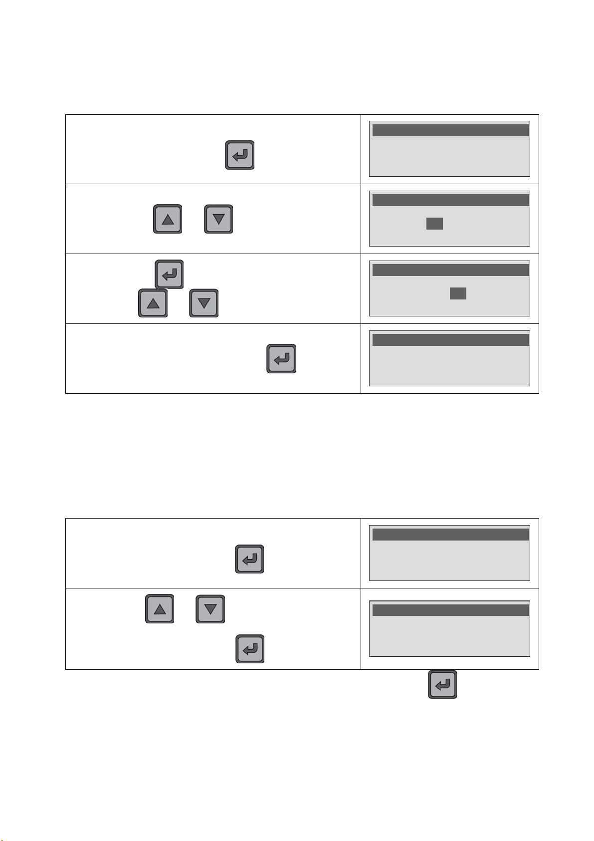
In the SYSTEM SETTINGS menu, select the Hour function and
validate with the
By using the and keys, adjust the hour.
Validate with the key, to skip to the minutes adjust, by
using the
To save the hour, validate with the key
and keys, adjust the minutes.
key.
Date : 10/08/09
>Hour : 10:25
Backlight : 60%
Date : 10/08/09
Hour : 10:25
Backlight : 60%
Date : 10/08/09
Hour : 10:25
Backlight : 60%
Date : 10/08/09
>Hour : 10:25
Backlight : 60%
2.3. LIGHTING THE SCREEN
The brightness of the backlighting can be set so as to suit the backlighting to the
ambient lighting or your personal preferences. The screen backlighting is programmable
and can be altered. This adjust is from 0% (backlight off) to 100% (maximum light).
Backlighting of low brightness will save battery power. Specify a setting that suits the
way you use the instrument.
In the SYSTEM SETTINGS menu, select the Backlight function
and validate with the
key.
Date : 10/08/09
Hour : 10:25
>Backlight : 60%
By using the and keys, select the backlight
intensity from 0 % (off) to 100 % (maximum) by step of 10 %
then validate with the
Key.
Date : 10/08/09
Hour : 10:25
Backlight : 80% <
Note: the backlight intensity is modified after the validation with the key.
UM-30300D-U User manual AX 6000 Page 37 / 54
Page 50
Chapter 4 – Functions of the instrument
SYSTEM
SETTINGS
MENU
SYSTEM
SETTINGS
MENU
SYSTEM
SETTINGS
MENU
SYSTEM
SETTINGS
MENU
2.4. AUTO OFF
This feature conserve battery life by automatically turning the instrument off after a userdefined period of time within there has been no key activity.
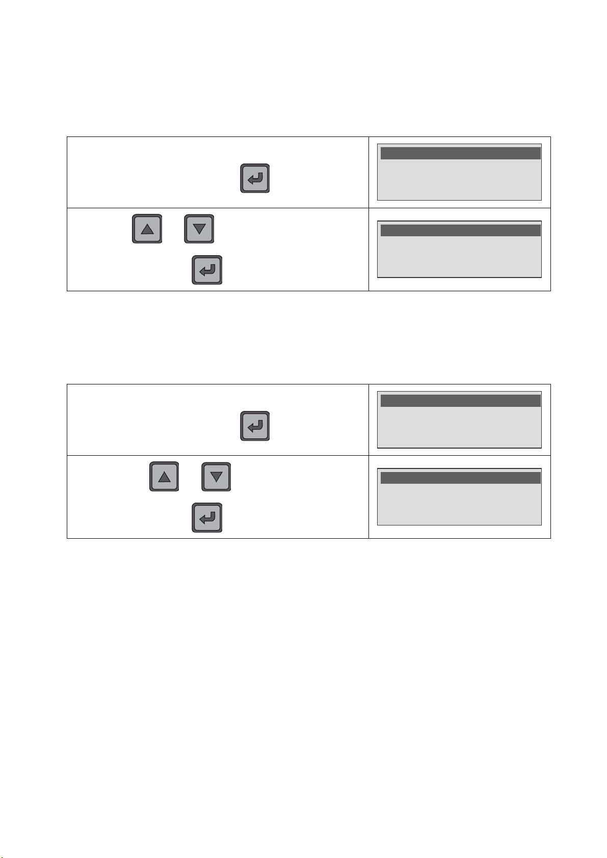
In the SYSTEM SETTINGS menu, select the Auto Off function
and validate with the
key.
Hour : 10:25
Backlight : 60%
>Auto Off : No
By using the and keys, adjust the time before turn
off from No (never turn off) to 30 minutes. Validate with the
key.
Hour : 10:25
Backlight : 60%
Auto Off : 20 min<
2.5. BUZZER
The Buzzer function allows ringing beeps. When this function is on, a beep is ringing
during all the measurement time. When the device detects a fail part or an alarm, a
series of short beeps are ringing.
In the SYSTEM SETTINGS menu, select the Buzzer function
and validate with the
key.
Hour : 10:25
Backlight : 60%
>Auto Off : No
By using the and keys, select On or Off to
validate or not the beep ringing and then confirm by using the
key.
Backlight : 60%
Auto Off : No
>Buzzer : On
UM-30300D-U User manual AX 6000 Page 38 / 54
Page 51
Chapter 4 – Functions of the instrument
SYSTEM
SETTINGS
MENU
SYSTEM
SETTINGS
MENU
SYSTEM
SETTINGS
MENU
2.6. AUTOMATIC START
The Automatic start function allows validating the automatic trigger of the measurement
when the accessories are making an electric contact with the part to control (current
control).
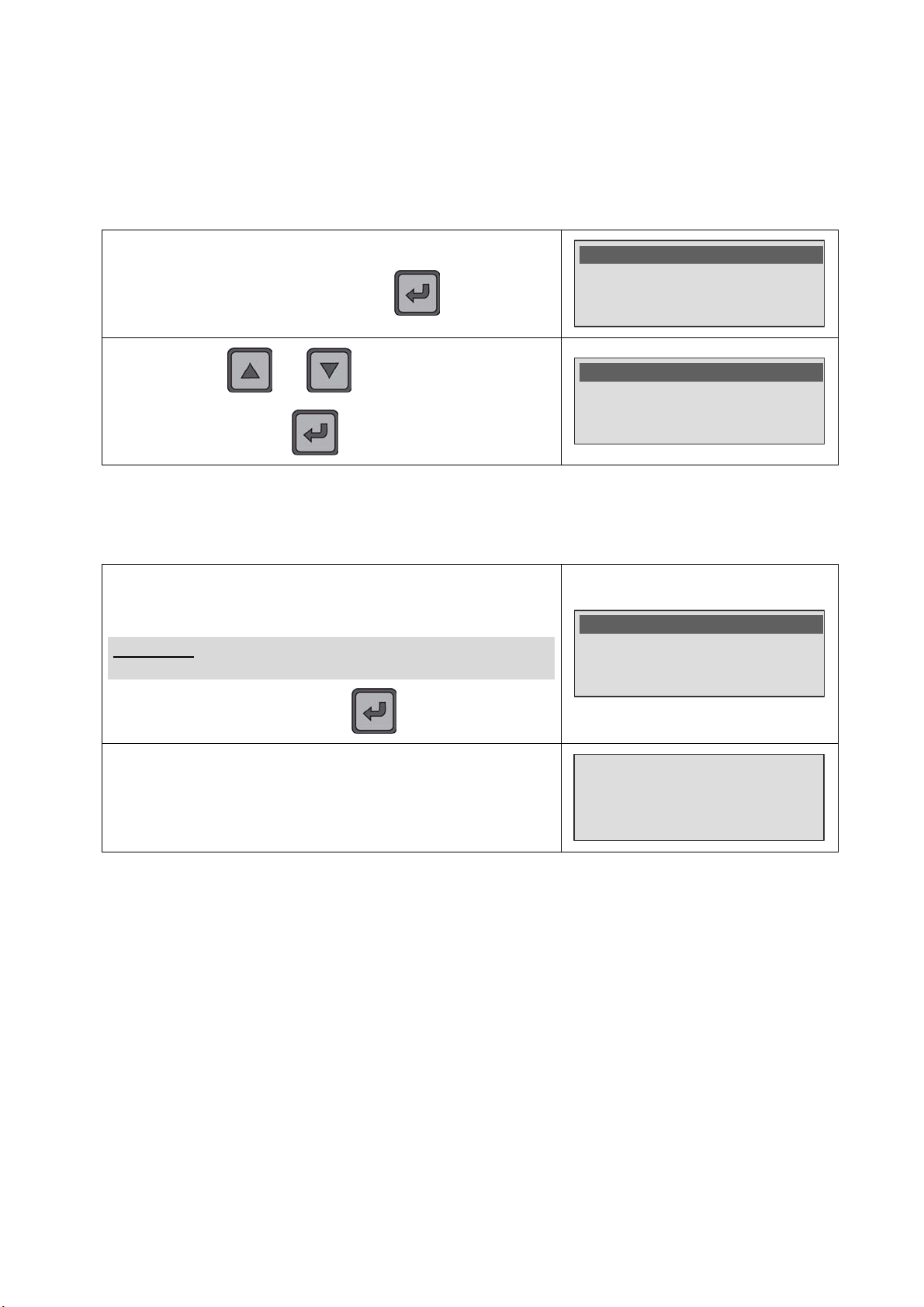
In the SYSTEM SETTINGS menu, select the Auto Start
function and validate with the
By using the and keys, select On or Off to
validate or not the automatic start and then confirm by using the
key.
key.
>Auto Start : Off
Reset program
reset all programs
>Auto Start : On
Reset program
reset all programs
2.7. PROGRAMS DELETION
This function will erase one or all the programs to reset them.
In the SYSTEM SETTINGS menu, select the Reset program
function to delete the current program or Reset all programs.
To delete all the programs contained in the device.
Warning! : Until the validation, the program or all the
programs will be definitively deleted!
Validate with the key.
Auto Start : On
>Reset program
reset all programs
The instrument deletes the program or all.
Reseting program
UM-30300D-U User manual AX 6000 Page 39 / 54
Page 52

Chapter 4 – Functions of the instrument
3. DATA MANAGEMENT
3.1. RESULTS STORAGE
The device is fitted with an internal memory greater than 1 Go only used for the results
storage, that allows recording several thousands of measurements results. Each
measurements carried out are automatically save at the end of the test.
The results recovery is only carried out from the Winateq300 software; in this
paragraph we will show some frames examples.
3.1.1. Manual mode results frames (Program)
The measurements values and some parameters are stored to be export for later use.
Prog
N°.
Program
name
1 R WING 10 A 1050mΩ 0mΩ 1029 mOhm PASS 23/09/09 09:15:48 01254
2 L WING 1A 1060mΩ 0mΩ 1012 mOhm PASS 23/09/09 09:17:52 01254
3 NOSE 0,1A 1035mΩ 0mΩ 0 mOhm FAIL 23/09/09 09:20:16 01254
Test
Current
Max
Reject.
Min
Reject
Measu
re
Unity Results Date Hour
Serial
N°
3.1.2. Automatic mode frames (Sequence)
In the automatic mode the following fields will be added:
9 Sequence N°.
9 Sequence name (ex: plane reference).
9 Program step in the sequence (from 1 to 999).
9 User identifier.
Seq
Seq
N°
Name
1 A320 1 9 WING Left Front 10 A 1050mΩ 0mΩ 1029 mOhm PASS 04/02/13 09:55:38 Jack 01254 0101
1 A320 2 3 WING Right Front 1A 1060mΩ 0mΩ 1012 mOhm FAIL 04/02/13 09:57:52 Jack 01254 0101
1 A320 3 2 NOSE Front mΩ mΩ mOhm TO DO 01254 0101
1 A320 4 5 STAB Right 1A 1050mΩ 0mΩ 952 mOhm PASS 04/02/13 10:03:08 Jack 01254 0101
1 A320 5 5 STAB Rear 1A 1075mΩ 0mΩ mOhm N/A 04/02/13 10:06:17 Jack 01254 0101
Step
Prog
Name 1 Name 2 Name 3 Test
N°
current
Max
Reject
Min
Reject
Measure
(R)
Unit Result Date Hour User
Serial
N°
Serial
N° 2
UM-30300D-U User manual AX 6000 Page 40 / 54
Page 53
Chapter 4 – Functions of the instrument
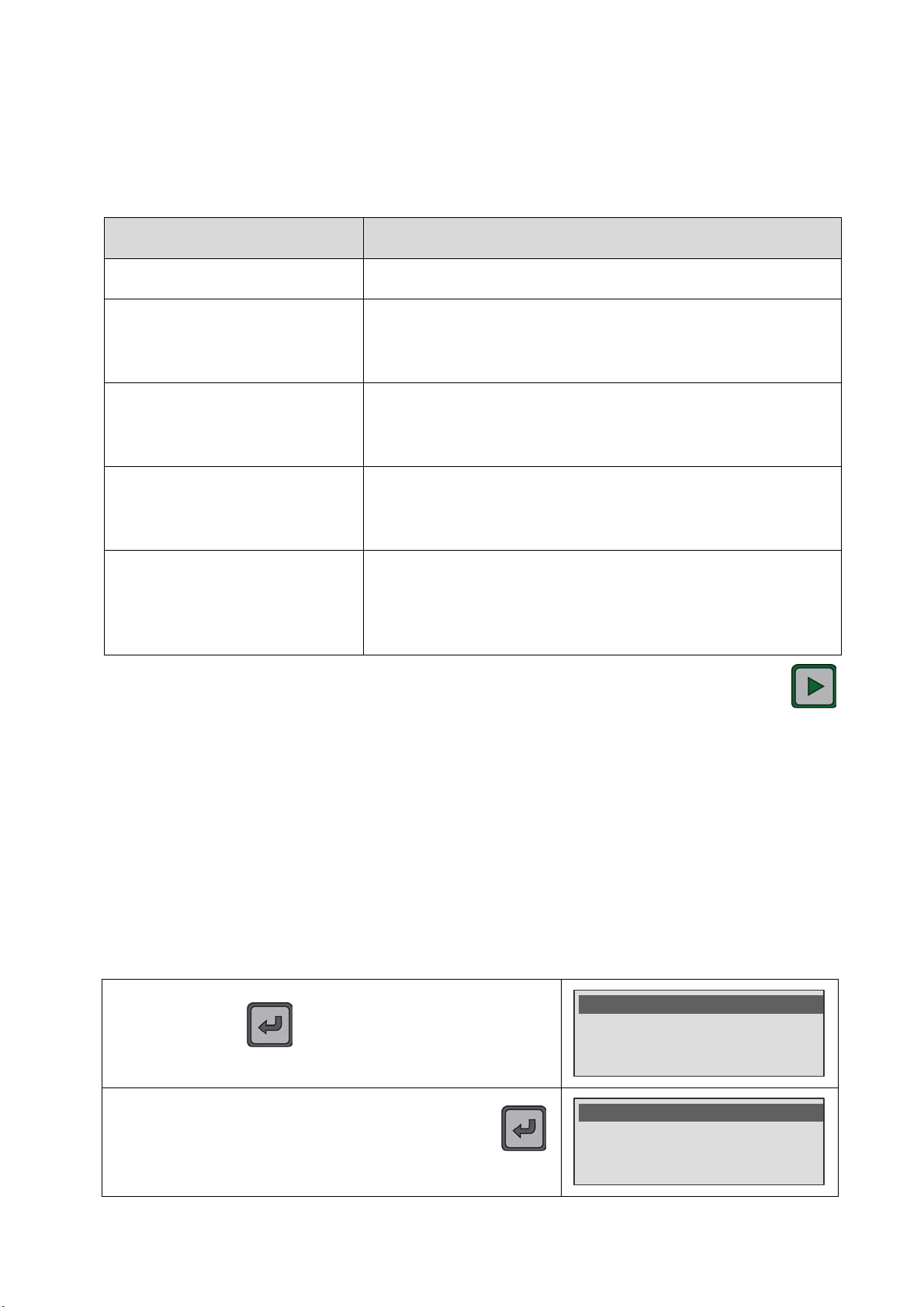
SPECIAL CYCLES
SPECIAL CYCLES
3. SPECIALS CYCLES MENU
3.1. SPECIAL CYCLES AVAILABLE
The following list shows all the special cycles which are available in the instrument:
Special cycle Function
9 Auto-test: Special cycle used to check the test current.
To delete the current sequence, canceling all the tests
9 Sequence delete*:
carried out in the sequence and starts the sequence
from the beginning.
Allows displaying all the tests which are to do in the
9 Tests –TO DO-*:
current sequence (or the ones which have been
skipped). This is to ease the "to do" steps to retrieve.
Allows displaying all the steps which have been
9 Tests – CANCEL-*:
cancelled in the current sequence. This is to ease the
cancelled steps to retrieve.
This special cycle delete all the results stored in the
9 Erase results:
internal memory. This operation deletes all definitively. It
is advisable to make a backup of the results before
deleting (see the Winateq300 user manual).
To start a special cycle, select it in the "Special cycles" menu and press on the
key. The cycle stops automatically.
* For further information about the sequences and the corresponding specials cycle, see
the chapter 3, paragraph 8: "Sequence mode running".
3.2. RUN SPECIALS CYCLES
3.2.1. Auto-test
Special cycle used to check test current.
Press on the key (brief press) to enter in the
Select the Auto test special cycle then confirm with the
UM-30300D-U User manual AX 6000 Page 41 / 54
Special Cycles menu.
key.
>Auto test : None
Erase Results
>Auto test : None
Erase Results
Page 54
Chapter 4 – Functions of the instrument
AUTO TEST
RANGE
P
SPECIAL CYCLES
SPECIAL CYCLES
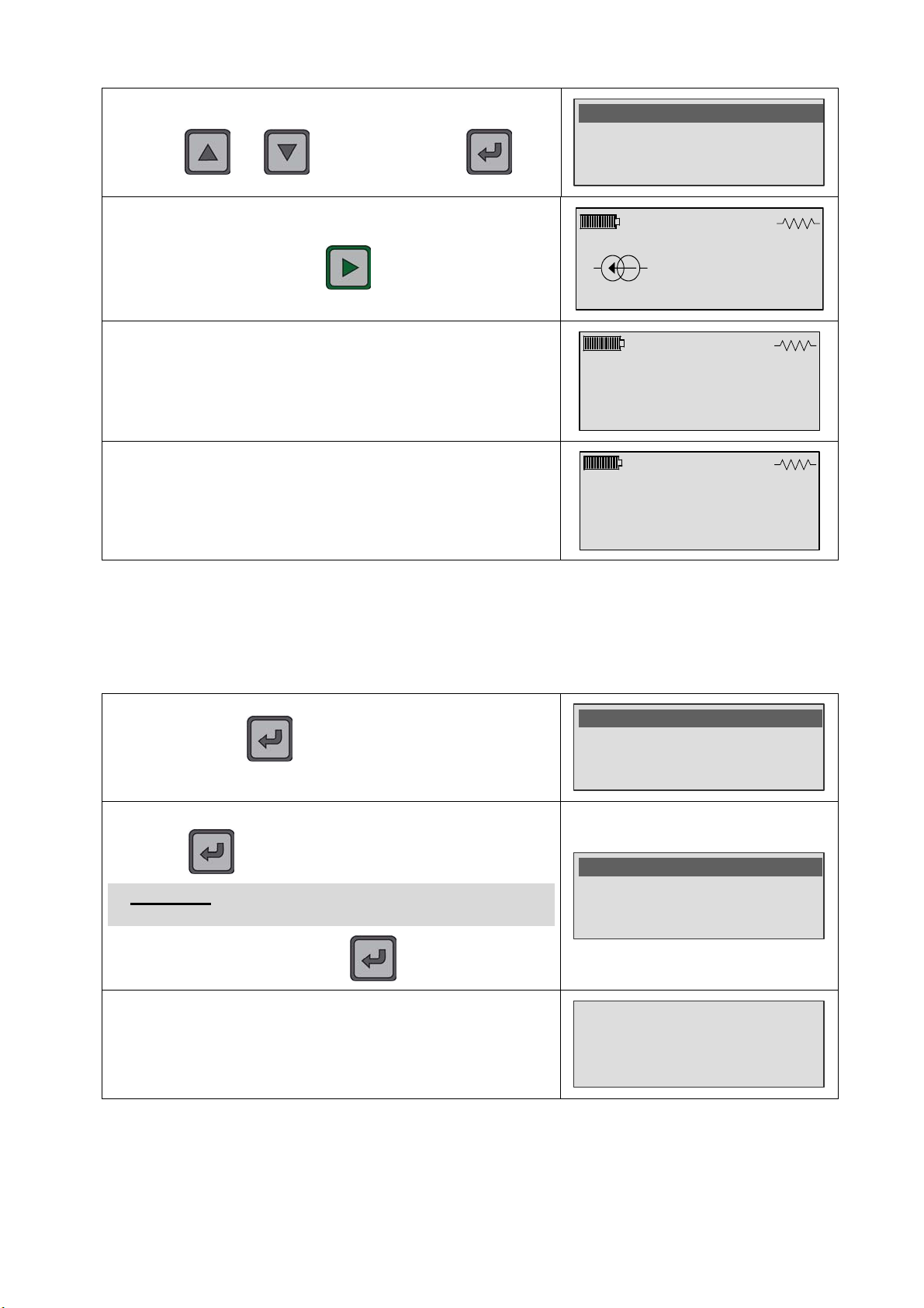
Select the range to check among 100 mA, 1 A and 10 A, by
using the
The instrument confirms the special cycle and the selected
current. Start the test with the
At the test end, the instrument displays the result which may be
If the current value is not correct, the instrument displays an
ALARM to indicate a current measurement fault.
and keys, confirm with the key.
key. Example 1 A range.
equal or near of the current value checked.
None
100mA
>1A
Program 1
1A
ressX to continue
AUTO TEST
1.000 A
PASS
AUTO-TEST
0.990 A
ALARM
3.2.2. Results deletion
This special cycle erase all the results stored in the instrument. The results will be
definitively deleted. It is advisable to save them first if archiving or later statistic
treatments are required. For the save, see the Winateq300 software user manual.
Press on the key (brief press) to enter in the
Special Cycles menu.
>Auto test : None
Erase Results
Select the special cycle Erase Results then confirm with the
key to delete all the results stored.
Warning! : Until the validation, the results will be
Auto test : None
>Erase Results
definitively deleted!
Confirm with the key.
The instrument confirms the results deletion.
Resetting results
UM-30300D-U User manual AX 6000 Page 42 / 54
Page 55
1. ACCESSORIES
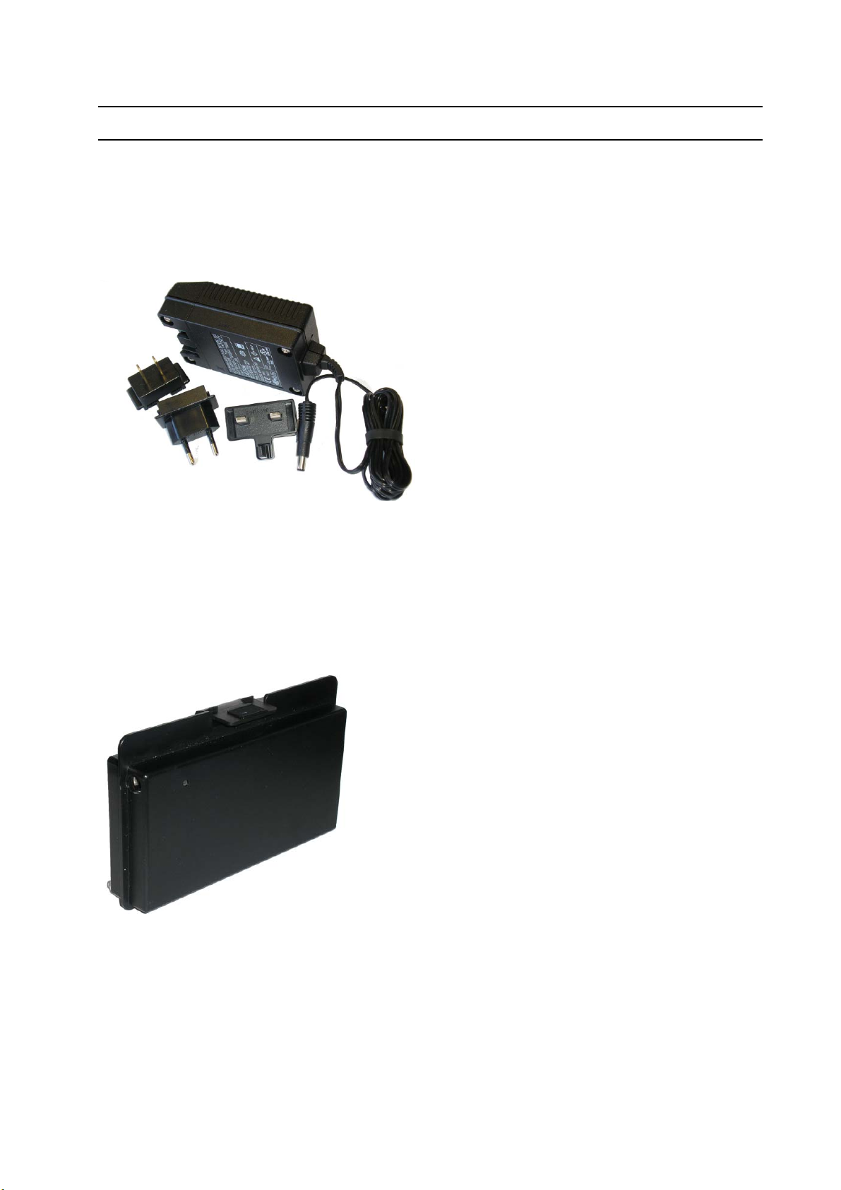
1.1. POWER SUPPLY
Chapter 5
ACCESSORIES
The power supply (fitted with the
instrument) converts a network voltage
(100 to 240 V AC) into a 24 V DC low
voltage supply. It has no power switch
and works as soon as it is plugged in.
It allows supplying the battery device
which manage itself the charge.
It is protected against surges and short
circuits via a thermal fuse (do not use
any other type of fuse).
Chapter 5 - Accessories
Moreover, this supply can be plugged on all types of electrical plugs using different
removable pins.
The instrument is not designed to work during the battery charge.
1.2. BATTERY
The 12V DC 4400 mA/h battery with Lithium Polymer
(Li-Po) technology is integrated into a case of our
design.
The charge is doing with the power supply which is
directly plugged on the battery with a jack connector.
The battery is fitted with a LED which indicates the
charge state.
The battery charge time is less than 3 hours. The
charge can be carried out without the battery
installed on the instrument.
See the battery use conditions in the "Safety
precautions" paragraph in the appendices.
2 batteries are supplied with the instrument.
UM-30300D-U User manual AX 6000 Page 43 / 54
Page 56
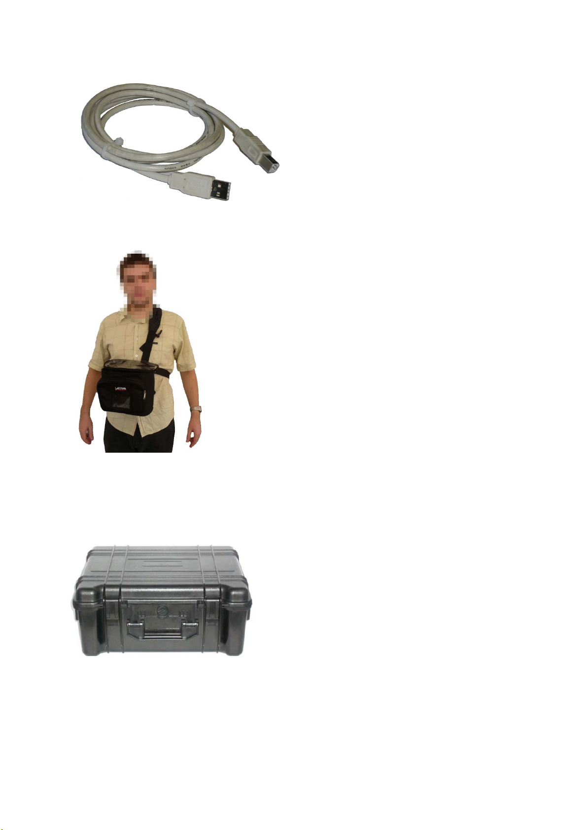
1.3. USB CABLE
Chapter 5 - Accessories
The USB cable (supplied with the device)
allows the connection between the
instrument and a personal computer.
1.4. S
OFT CARRYING CASE
The soft carrying case allows the user to carry easier the
device on the test area.
1.5. T
RANSPORT CASE
Strong case with the dimensions: Large 520, Depth 440 and high 230 for the storage of
the following components:
9 1 measurement device AX6000,
9 1 second battery,
9 1 power supply for battery charging,
9 1 probe small size,
9 1 probe long size,
9 1 Kelvin probe pliers,
9 1 VN/VG cable.
UM-30300D-U User manual AX 6000 Page 44 / 54
Page 57
Chapter 6 –Error messages
Chapter 6
ERROR MESSAGES
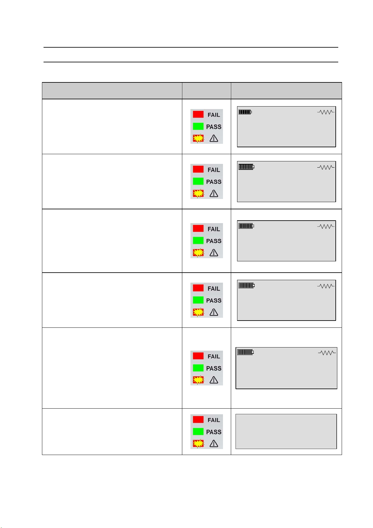
The ATEQ AX6000 can display error messages if there are operational problems.
PROBLEM LIGHTS DISPLAYED MESSAGES
OOVVEERR RRAANNGGEE
The measure is out of the full scale.
Action: take another measurement
range, or configure the instrument in
automatic range.
CCOONNTTIINNUUIITTYY UU FFAAUULLTT
Contact break on the voltmeter loop.
Action: restart a measurement, if the
problem persists, check the contact
quality accessories and fittings.
CCOONNTTIINNUUIITTYY II FFAAUULLTT
Contact break on the current generator
loop.
Action: restart a measurement, if the
problem persists, check the contact
quality accessories and fittings.
MMEEAASSUURREEMMEENNTT FFAAIILLUURREE
Measurement board failure.
Action: turn off and restart the device, if
the problem persists, contact the ATEQ
after sale service.
Program 1
OVER
RANGE
10A 6mΩ
Program 1
CONTINUITY U
FAULT
10A Auto
Program 1
CONTINUITY I
FAULT
10A Auto
Program 1
MEASUREMENT
FAILURE
10A Auto
AAUUTTOOTTEESSTT AALLAARRMM
Auto-test fault. The internal auto-test
cycle result is fail, so the test current is
on wrong value.
AUTO-TEST
102 mA
Action: make one or several auto-test
ALARM
cycles on all the ranges, if the problem
persists, contact the ATEQ after sale
service.
PPaasssswwoorrdd eerrrroorr
The password entered is wrong.
Password Error
Action: try again with the right
password.
UM-30300D-U User manual AX 6000 Page 45 / 54
Page 58
Chapter 6 –Error messages
PROBLEM LIGHTS DISPLAYED MESSAGES
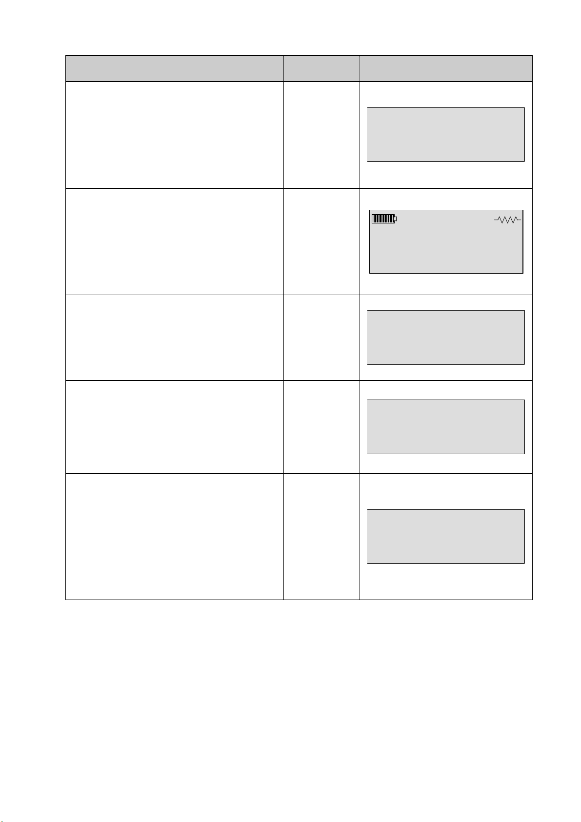
MMEEMMOORRYY EERRRROORR
The internal memory is full. The device
can run measurements, but the results
and the programs modifications are not
saved.
Action: empty the memory (delete some
results files).
SSDD CCAARRDD FFAAUULLTT
Internal memory failure. The device can
run measurements, but the results and
the programs modifications are not
saved.
Action: contact ATEQ after sales
services.
SSYYSSTTEEMM EERRRROORR
A fatal internal system error occurs.
Action: try to switch of and restart the
instrument, if the problem persists,
contact ATEQ after sales services.
MEMORY ERROR
Programme 1
10A Auto
SD CARD
FAULT
SYSTEM ERROR
CCOONNFFIIGGUURRAATTIIOONN EERRRROORR
A fatal internal configuration error
occurs.
Action: try to switch of and restart the
instrument, if the problem persists,
contact ATEQ after sales services.
PPAARRAAMMEETTEERRSS EERRRROORR
One or several parameters in the test
parameters or in the system settings or
not compatible.
Action: try to make a reset of the
system and restart the instrument, if the
problem persists, contact ATEQ after
sales services.
CONFIGURATION
ERROR
PARAMETERS
ERROR
UM-30300D-U User manual AX 6000 Page 46 / 54
Page 59

Chapter 7 - Operational problems
Chapter 7
OPERATIONAL PROBLEMS
1. PROBABLES FAILURES
If a failure with the device appears, see the following list (left column) to identify the
fault, make checks or actions steps (right column) in the same order.
Identified failure Remedial action
1 – The device doesn't turn on. 1) Charge fully the battery.
2) Change the battery by a new one.
3) Check the electrics contacts between the
battery and the device.
4) Contact the ATEQ after sales service.
2 – Wrong or false measures. 1) Check the battery charge.
2) Repeat the measurement test, by pressing
strongly the probes to improve the contact
3) Check the quality of the electrics contacts of
the probes, Kelvin probes or others
accessories.
4) Check the probes connection.
5) Check the wires between the probes and the
device (winding, etc.).
6) Contact the ATEQ after sales service.
3 – Erroneous or erratic measures. 1) Check the battery charge.
2) Repeat the measurement test, by pressing
strongly the probes to improve the contact
3) Check the quality of the electrics contacts of
the probes, Kelvin probes or others
accessories.
4) Check the probes connection.
5) Check the wires between the probes and the
device (winding, etc.).
6) Check the device calibration, if it fails send
back the device to the ATEQ after sales
service.
7) Contact the ATEQ after sales service.
The ATEQ Company disclaims any responsibility if the instruments calibration and
adjustment would not be performed by its services.
UM-30300D-U User manual AX 6000 Page 47 / 54
Page 60

Chapter 7 - Operational problems
UM-30300D-U User manual AX 6000 Page 48 / 54
Page 61
Appendices
ATEQ AX6000
1. TECHNICALS CHARACTERISTICS
Appendices
Power supply:
Battery:
Weight (kg): About 2,8
Display :
Temperatures:
Use and battery charge: 0° C to +45°C (+32° F to +113° F)
Storage (battery conditions): -10° C to +50° C (+14° F to +122° F)
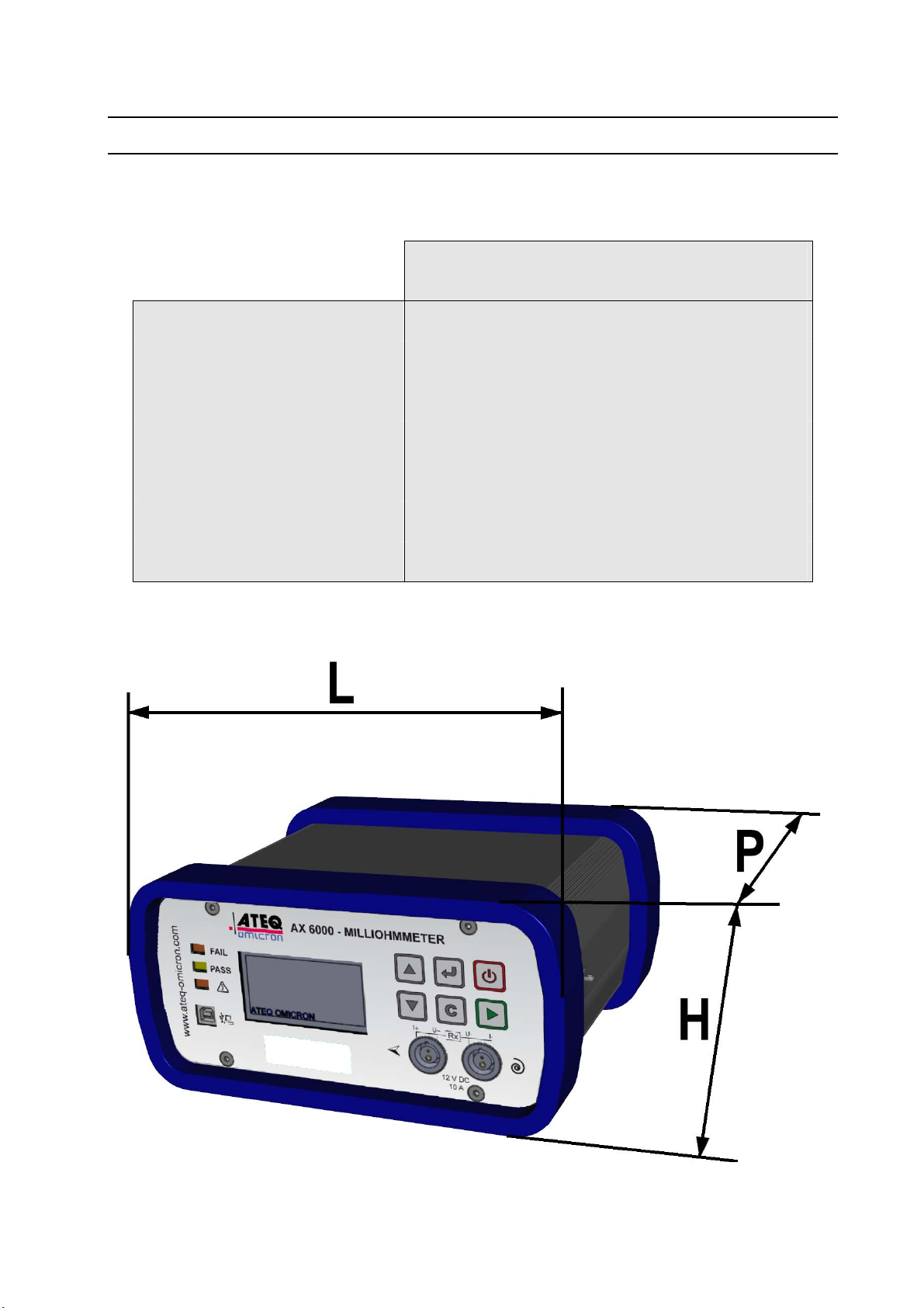
2. DIMENSION DRAWING
Lithium Polymer (see safety information below)
24 V DC concentric jack
LCD 4 lines 60 mm x 32 mm
AX 6000
L: 240 mm / H: 120 mm / D: 210 mm.
UM-30300D-U User manual AX 6000 Page 49 / 54
Page 62

Appendices
3. SAFETY INFORMATION
You must read and understand these safety instructions and warnings before using or
charging your lithium polymer batteries.
Operating environment
Remember to follow any special current regulations any area, and always switch off your device
when its use is prohibited or when it may cause interference or danger.
Use the device only in its normal operating positions.
Your device and its enhancements may contain small part. Keep them out of the reach of small
children.
About Charging
Use only the charger supplied with your device. Use of another type of charger will result in
malfunction and/or danger.
Use the specified battery in the equipment.
When the green LED turns off, the charge is complete.
About the Charger
Do not use the charger in a high moisture environment. Never touch the charger when your
hands or feet are wet.
Allow ventilation around the charger when using it. Do not cover the charger with paper or other
objects that will reduce cooling. Do not use the charger while it is inside a carrying case.
Connect the charger to a proper power source. The voltage requirements are found on the
product case and/or packaging.
Do not use the charger if the wires become damaged. Do not attempt to service the unit. There
are no serviceable parts inside. Replace the unit if it is damaged or exposed to excess moisture.
This charger is not a toy and should not be used by children or infirm persons without proper
training or supervision.
Do not use it as a power source.
Unplug it before attempting to service or clean it.
About the Battery
CAUTION: This unit contains an internal Lithium Polymer battery. The battery can burst or
explode, releasing hazardous chemicals. To reduce the risk of fire or burns, do not disassemble,
crush, pierce or dispose of the battery or the instrument in fire or water, do not short circuit or
short the contacts with a metal object.
Use a specified charger approved by the ATEQ manufacturer and supplied with the device.
Safety for Lithium Polymer battery use
NEVER leave the battery unattended during the charging process. Remove the battery on a
nonflammable surface. The battery must imperatively be placed on a non-flammable surface
during charging (ceramic platter or metal box).
Charge the Lithium Polymer battery ONLY with the charger provided.
NEVER use a Ni-MH (Nickel Metal Hydride) type battery charger to charge a Lithium Polymer
battery.
UM-30300D-U User manual AX 6000 Page 50 / 54
Page 63

Appendices
If the battery begins to overheat more than 60°C (140° F), STOP IMMEDIATELY the charge.
The battery should NEVER exceed 60°C (140° F) during the charging process.
NEVER charge a battery pack immediately after use and while still hot. Leave it cool down to
ambient temperature.
If you see some smoke or some liquid out of the battery, stop the charge immediately.
Disconnect the battery from the charger and place it in an isolated area for at least 15 minutes.
DO NOT USE THE BATTERY AGAIN, but replace it with new one.
Keep a fire extinguisher for electrical fires handy while charging the battery. In the unlikely event
that the Lithium Polymer battery will ignite, DO NOT use water to extinguish the fire, take some
sand or fire extinguisher described above.
Do not pierce, cut or NEVER compress the jacket of a Lithium Polymer battery. If the battery is
swelling up or if the cover is damaged, DO NOT USE AGAIN. Replace with a new one.
It must neutralize the Lithium Polymer battery elements unusable. The neutralization process
must be performed with very strict security fit. It is recommended that you contact a specialist in
this type of battery to perform this task, which is responsible to collect the battery out of use and
gives to a specialized recycler.
Do not dispose of Lithium Polymer batteries to the dustbin.
The Lithium Polymer battery is not suitable for children under 14 years. Do not let a Lithium
Polymer battery reach of children
To prevent leakage or other hazards, do not store batteries above 60°C (140°F). Never leave
the battery inside a car (for example) where the temperature could be very high or in a place
where temperatures could exceed 60°C (140°F). Store the battery in a dry place to avoid
contact with liquid, whatever the type. Store the battery only on a nonflammable surface, heat
resistant, non conductive and away from all flammable materials or sources. Always store the
battery out of reach of children.
A Lithium Polymer battery should be stored with a minimum charge of 30%. If you store
completely discharged, it will quickly become unusable.
If you don't follow these safety precautions, you may cause serious personal injury and damage
to property; you may even cause a fire!
The ATEQ Company disclaims any responsibility for damage sustained in case of non
compliance with these safety instructions.
Using a Lithium Polymer battery has a high risk of fires and can cause serious damages to
property and persons, the user agrees to accept the risk and responsibility.
The ATEQ Company couldn't control the proper use of the battery for each customer (charge,
discharge, storage etc.), It can not be held responsible for damage to persons and property.
Important instructions (for service personnel only)
CAUTION: Risk of explosion if battery is replaced by an incorrect type. Dispose of used
batteries according to the instructions.
Replace only with the same or equivalent type recommended by the manufacturer ATEQ.
Use the battery only in the specified equipment.
The battery must be recycled or disposed of properly.
UM-30300D-U User manual AX 6000 Page 51 / 54
Page 64
Appendices
4. RECYCLING
Do not dispose of the rechargeable Lithium-Ion battery or the device
to the dustbin.
These components must be collected and recycled.
The crossed-out wheeled dustbin means that within the EU the product
must be taken to separate collection at the product end-of life. This applies
to your tool but also to any enhancements marked with this symbol. Do not
dispose of these products as unsorted municipal waste. For further
information, please contact ATEQ.
UM-30300D-U User manual AX 6000 Page 52 / 54
Page 65

A
Alarm .................................................. 13
Auto off ............................................... 38
Automatic mode..................................24
Automatic start....................................39
Automatic zero......................................5
Auto-test ....................................... 25, 41
B
Backlight.............................................37
Battery ................................................ 50
Battery charge indicator........................ 8
Brightness...........................................37
Buzzer ................................................38
C
Cancel test..........................................31
Caution ............................................... 50
Chaining PP..................................24, 29
Charger ..............................................50
Charging............................................. 50
Clock ..................................................36
Control ranges ....................................23
Create sequence ................................27
Crossed-out wheeled dustbin .............52
Current ...............................................22
Cycle stop...........................................25
D
Data management .............................. 40
Date.................................................... 36
Delete results......................................42
Delete sequence.................................31
Dimensions.........................................49
E
Electrics connectors .............................8
Environment .......................................50
Error messages ..................................45
F
Fail part light .......................................13
Faults, errors and remedies................47
Frames ............................................... 40
H
Hour.................................................... 37
I
I key.................................................... 12
Inductive mode ...................................23
Insert program ....................................27
Instrument autonomy............................ 5
K
Keyboard ............................................12
L
Language............................................35
Lights.................................................. 13
Index
Index
Lock / Unlock ......................................18
M
Main menu..........................................33
Maximum reject ..................................22
Measurement characteristics................6
Measurement modes ..........................23
Measurement principle .........................3
Measurements fail ..............................25
Minimum reject ...................................23
N
Navigation keys ..................................12
P
Parameters adjust...............................22
Pass part light.....................................13
Password............................................18
Password deletion ..............................19
Power supply ................................43, 50
Presentation .........................................7
Program name....................................22
Program number change ....................20
Program to run....................................20
Programs deletion...............................39
R
R Max .................................................22
R Min ..................................................23
Ranges ...............................................23
Ranges selection ..................................6
Recycling ............................................52
Resistive mode ...................................23
Results storage...................................40
Run specials cycles ............................41
S
Safety precautions ..............................50
Security...............................................50
Sequence cancellation........................32
Sequence management......................28
Sequence mode............................26, 29
Sequence saved .................................32
Sequence validation ...........................32
Specials cycles ...................................41
Specials cycles menu .........................34
Start cycle...........................................25
System settings ..................................35
T
Technical characteristics ....................49
Test current ........................................22
Test program creation.........................21
Test trigger .........................................25
Tests – CANCEL - ..............................32
Tests – TO DO - .................................32
Tests Connectors..................................9
UM-30300D-U User manual AX 6000 Page 53 / 54
Page 66

Index
Tests -N/A- .........................................32
Turn on ............................................... 17
Turn on key.........................................12
U
USB ......................................................9
W
What to do in case of failure? .............47
UM-30300D-U User manual AX 6000 Page 54 / 54
Page 67

Page 68

This document is the exclusive property of ATEQ.
It may not be communicated, reproduced or used without prior consent.
 Loading...