

ATEN VM1600, VM7514, VM8514, VM7804, VM8804 User Manual
...
Modular Matrix Solution Series
User Manual
Modular Matrix Switch
VM1600
4-Port HDBaseT Input / Output Board
VM7514 / VM8514
4-Port HDMI Input / Output Board
VM7804 / VM8804
4-Port DVI Input / Output Board
VM7604 / VM8604
4-Port VGA Input Board
VM7104
HDMI HDBaseT Lite Receiver with Scaler
VE805R
www.aten.com
Modular Matrix Solution User Manual
ii
EMC Information
FEDERAL COMMUNICATIONS COMMISSION INTERFERENCE
STATEMENT
This equipment has been tested and found to comply with the limits for a Class A digital
device, pursuant to Part 15 of the FCC Rules. These limits are designed to provide reasonable
protection against harmful interference when the equipment is operated in a commercial
environment. This equipment generates, uses, and can radiate radio frequency energy and, if
not installed and used in accordance with the instruction manual, may cause harmful
interference to radio communications. Operation of this equipment in a residential area is
likely to cause harmful interference in which case the user will be required to correct the
interference at his own expense.
FCC Caution: Any changes or modifications not expressly approved by the party
responsible for compliance could void the user's authority to operate this equipment.
CE Warning:
This is a class A product. In a domestic environment this product may cause radio
interference in which case the user may be required to take adequate measures.
RoHS
This product is RoHS compliant.
Safety
This product has been classified as Information Technology Equipment.
SJ/T 11364-2006
The following contains information that relates to China.

Modular Matrix Solution User Manual
iii
User Information
Online Registration
Be sure to register your product at our online support center:
Telephone Support
For telephone support, call this number:
User Notice
All information, documentation, and specifications contained in this manual
are subject to change without prior notification by the manufacturer. The
manufacturer makes no representations or warranties, either expressed or
implied, with respect to the contents hereof and specifically disclaims any
warranties as to merchantability or fitness for any particular purpose. Any of
the manufacturer's software described in this manual is sold or licensed as is.
Should the programs prove defective following their purchase, the buyer (and
not the manufacturer, its distributor, or its dealer), assumes the entire cost of all
necessary servicing, repair and any incidental or consequential damages
resulting from any defect in the software.
The manufacturer of this system is not responsible for any radio and/or TV
interference caused by unauthorized modifications to this device. It is the
responsibility of the user to correct such interference.
The manufacturer is not responsible for any damage incurred in the operation
of this system if the correct operational voltage setting was not selected prior
to operation. PLEASE VERIFY THAT THE VOLTAGE SETTING IS
CORRECT BEFORE USE.
International http://eservice.aten.com
International 886-2-8692-6959
China 86-10-5255-0110
Japan 81-3-5615-5811
Korea 82-2-467-6789
North America 1-888-999-ATEN ext 4988
United Kingdom 44-8-4481-58923

Modular Matrix Solution User Manual
iv
Package Contents
VM1600
The VM1600 package consists of:
1 VM1600 Modular Matrix Switch
1Power Cord
1 Terminal Block connector
1 Fan Module (pluggable)
1 Power Module (pluggable)
1 User Instructions*
VM7514 / VM8514
The 4-Port HDBaseT Input / Output Board package consists of:
1 VM7514 4-Port HDBaseT Input Board
1 VM8514 4-Port HDBaseT Output Board
4 Terminal Block connectors
1 IR Transmitter
1 IR Receiver
1 User Instructions*
VM7804 / VM8804
The 4-Port HDMI Input / Output Board package consists of:
1 VM7804 4-Port HDMI Input Board
1 VM8804 4-Port HDMI Output Board
4 Terminal Block connectors
1 User Instructions*
VM7604 / VM8604
The 4-Port DVI Input / Output Board package consists of:
1 VM7604 4-Port DVI Input Board
1 VM8604 4-Port DVI Output Board
4 Terminal Block connectors
1 User Instructions*

Modular Matrix Solution User Manual
v
VM7104
The 4-Port VGA Input Board package consists of:
1 VM7104 4-Port VGA Input Board
4 Terminal Block connectors
1 User Instructions*
VE805R
The HDMI HDBaseT Lite Receiver with Scaler package consists of:
1 VE805R HDMI HDBaseT Lite Receiver with Scaler
1 Power Adapter
1 User Instructions*
Check to make sure that all components are present and that nothing was
damaged in shipping. If you encounter a problem, contact your dealer. Read
this manual thoroughly and follow the installation and operation procedures
carefully to prevent any damage to the unit, and/or any of the devices
connected to it.
* Features may have been added to the VM1600 / VM7514 / VM8514 /
VM7804 / VM8804 / VM7604 / VM8604 / VM7104 / VE805R since this
manual was published. Please visit our website to download the most up-todate version.
© Copyright 2015 ATEN® International Co., Ltd.
Manual Date: 2015-10-26
VM1600 F/W Version: 1.5.145
VM8514 F/W Version: 1.0.069
VM7514 F/W Version: 1.0.066
ATEN and the ATEN logo are registered trademarks of ATEN International Co., Ltd. All rights reserved.
All other brand names and trademarks are the registered property of their respective owners.

Modular Matrix Solution User Manual
vi
Contents
EMC Information. . . . . . . . . . . . . . . . . . . . . . . . . . . . . . . . . . . . . . . . . . . . . ii
RoHS . . . . . . . . . . . . . . . . . . . . . . . . . . . . . . . . . . . . . . . . . . . . . . . . . . . . . ii
Safety . . . . . . . . . . . . . . . . . . . . . . . . . . . . . . . . . . . . . . . . . . . . . . . . . . . . . ii
SJ/T 11364-2006 . . . . . . . . . . . . . . . . . . . . . . . . . . . . . . . . . . . . . . . . . . . . ii
User Information . . . . . . . . . . . . . . . . . . . . . . . . . . . . . . . . . . . . . . . . . . . . .iii
Online Registration . . . . . . . . . . . . . . . . . . . . . . . . . . . . . . . . . . . . . . . .iii
Telephone Support . . . . . . . . . . . . . . . . . . . . . . . . . . . . . . . . . . . . . . . .iii
User Notice . . . . . . . . . . . . . . . . . . . . . . . . . . . . . . . . . . . . . . . . . . . . . .iii
Package Contents . . . . . . . . . . . . . . . . . . . . . . . . . . . . . . . . . . . . . . . . . . .iv
VM1600. . . . . . . . . . . . . . . . . . . . . . . . . . . . . . . . . . . . . . . . . . . . . . . . .iv
VM7514 / VM8514 . . . . . . . . . . . . . . . . . . . . . . . . . . . . . . . . . . . . . . . .iv
VM7804 / VM8804 . . . . . . . . . . . . . . . . . . . . . . . . . . . . . . . . . . . . . . . .iv
VM7604 / VM8604 . . . . . . . . . . . . . . . . . . . . . . . . . . . . . . . . . . . . . . . .iv
VM7104. . . . . . . . . . . . . . . . . . . . . . . . . . . . . . . . . . . . . . . . . . . . . . . . . v
VE805R. . . . . . . . . . . . . . . . . . . . . . . . . . . . . . . . . . . . . . . . . . . . . . . . . v
Contents . . . . . . . . . . . . . . . . . . . . . . . . . . . . . . . . . . . . . . . . . . . . . . . . . . .vi
About this Manual . . . . . . . . . . . . . . . . . . . . . . . . . . . . . . . . . . . . . . . . . . . .xi
Conventions . . . . . . . . . . . . . . . . . . . . . . . . . . . . . . . . . . . . . . . . . . . . . . . xii
Product Information . . . . . . . . . . . . . . . . . . . . . . . . . . . . . . . . . . . . . . . . . xii
Chapter 1.
Introduction
Overview. . . . . . . . . . . . . . . . . . . . . . . . . . . . . . . . . . . . . . . . . . . . . . . . . . . 1
Features . . . . . . . . . . . . . . . . . . . . . . . . . . . . . . . . . . . . . . . . . . . . . . . . . . . 3
VM1600. . . . . . . . . . . . . . . . . . . . . . . . . . . . . . . . . . . . . . . . . . . . . . . . . 3
VM7514 / VM8514 . . . . . . . . . . . . . . . . . . . . . . . . . . . . . . . . . . . . . . . . 4
VM7804 / VM8804 . . . . . . . . . . . . . . . . . . . . . . . . . . . . . . . . . . . . . . . . 4
VM7604 / VM8604 . . . . . . . . . . . . . . . . . . . . . . . . . . . . . . . . . . . . . . . . 5
VM7104. . . . . . . . . . . . . . . . . . . . . . . . . . . . . . . . . . . . . . . . . . . . . . . . . 5
VE805R. . . . . . . . . . . . . . . . . . . . . . . . . . . . . . . . . . . . . . . . . . . . . . . . . 5
Requirements . . . . . . . . . . . . . . . . . . . . . . . . . . . . . . . . . . . . . . . . . . . . . . . 7
Input / Output Board . . . . . . . . . . . . . . . . . . . . . . . . . . . . . . . . . . . . . . . 7
Source Devices. . . . . . . . . . . . . . . . . . . . . . . . . . . . . . . . . . . . . . . . . . . 7
Display Devices. . . . . . . . . . . . . . . . . . . . . . . . . . . . . . . . . . . . . . . . . . . 7
Cables . . . . . . . . . . . . . . . . . . . . . . . . . . . . . . . . . . . . . . . . . . . . . . . . . . 7
Optional Equipment. . . . . . . . . . . . . . . . . . . . . . . . . . . . . . . . . . . . . . . . 8
Components . . . . . . . . . . . . . . . . . . . . . . . . . . . . . . . . . . . . . . . . . . . . . . . . 9
VM1600 Front View. . . . . . . . . . . . . . . . . . . . . . . . . . . . . . . . . . . . . . . . 9
VM1600 Rear View . . . . . . . . . . . . . . . . . . . . . . . . . . . . . . . . . . . . . . . 11
VM7514 Front View. . . . . . . . . . . . . . . . . . . . . . . . . . . . . . . . . . . . . . . 13
VM8514 Front View. . . . . . . . . . . . . . . . . . . . . . . . . . . . . . . . . . . . . . . 13
VM7804 Front View. . . . . . . . . . . . . . . . . . . . . . . . . . . . . . . . . . . . . . . 14
VM8804 Front View. . . . . . . . . . . . . . . . . . . . . . . . . . . . . . . . . . . . . . . 14
VM7604 Front View. . . . . . . . . . . . . . . . . . . . . . . . . . . . . . . . . . . . . . . 15

Modular Matrix Solution User Manual
vii
VM8604 Front View. . . . . . . . . . . . . . . . . . . . . . . . . . . . . . . . . . . . . . .15
VM7104 Front View. . . . . . . . . . . . . . . . . . . . . . . . . . . . . . . . . . . . . . .16
VE805R Front View. . . . . . . . . . . . . . . . . . . . . . . . . . . . . . . . . . . . . . .17
VE805R Rear View . . . . . . . . . . . . . . . . . . . . . . . . . . . . . . . . . . . . . . . 17
Chapter 2.
Hardware Setup
Rack Mounting . . . . . . . . . . . . . . . . . . . . . . . . . . . . . . . . . . . . . . . . . . . . .19
Mounting with Brackets . . . . . . . . . . . . . . . . . . . . . . . . . . . . . . . . .20
Grounding . . . . . . . . . . . . . . . . . . . . . . . . . . . . . . . . . . . . . . . . . . . . . . . . . 21
Input / Output Board Installation . . . . . . . . . . . . . . . . . . . . . . . . . . . . . . . .22
Cable Connection . . . . . . . . . . . . . . . . . . . . . . . . . . . . . . . . . . . . . . . . . . . 24
Installation Diagram. . . . . . . . . . . . . . . . . . . . . . . . . . . . . . . . . . . . . . . 25
Chapter 3.
Front Panel Operation
Overview . . . . . . . . . . . . . . . . . . . . . . . . . . . . . . . . . . . . . . . . . . . . . . . . . . 27
Front Panel Pushbuttons. . . . . . . . . . . . . . . . . . . . . . . . . . . . . . . . . . . . . .27
Basic Navigation . . . . . . . . . . . . . . . . . . . . . . . . . . . . . . . . . . . . . . . . . 27
Front Panel LCD . . . . . . . . . . . . . . . . . . . . . . . . . . . . . . . . . . . . . . . . . . . . 28
LCD Password . . . . . . . . . . . . . . . . . . . . . . . . . . . . . . . . . . . . . . . . . .28
Port Switching . . . . . . . . . . . . . . . . . . . . . . . . . . . . . . . . . . . . . . . . . . . . . .29
Video / Audio Pushbutton . . . . . . . . . . . . . . . . . . . . . . . . . . . . . . . . . .29
Output Port Selection. . . . . . . . . . . . . . . . . . . . . . . . . . . . . . . . . . .31
Profile Pushbutton . . . . . . . . . . . . . . . . . . . . . . . . . . . . . . . . . . . . . . . .33
LCD Menu . . . . . . . . . . . . . . . . . . . . . . . . . . . . . . . . . . . . . . . . . . . . . . . . .34
LCD Main Screen . . . . . . . . . . . . . . . . . . . . . . . . . . . . . . . . . . . . . . . .35
IP Setting. . . . . . . . . . . . . . . . . . . . . . . . . . . . . . . . . . . . . . . . . . . . . . . . . . 36
Serial Port Setting . . . . . . . . . . . . . . . . . . . . . . . . . . . . . . . . . . . . . . . . . . .37
Serial Port Address Setting . . . . . . . . . . . . . . . . . . . . . . . . . . . . . .37
Baud Rate . . . . . . . . . . . . . . . . . . . . . . . . . . . . . . . . . . . . . . . . . . . 38
Serial Port Mode . . . . . . . . . . . . . . . . . . . . . . . . . . . . . . . . . . . . . .38
Operation Mode . . . . . . . . . . . . . . . . . . . . . . . . . . . . . . . . . . . . . . . . . . . . 40
EDID . . . . . . . . . . . . . . . . . . . . . . . . . . . . . . . . . . . . . . . . . . . . . . .40
CEC . . . . . . . . . . . . . . . . . . . . . . . . . . . . . . . . . . . . . . . . . . . . . . . . 42
OSD . . . . . . . . . . . . . . . . . . . . . . . . . . . . . . . . . . . . . . . . . . . . . . . .43
Output Status. . . . . . . . . . . . . . . . . . . . . . . . . . . . . . . . . . . . . . . . .44
Security Mode . . . . . . . . . . . . . . . . . . . . . . . . . . . . . . . . . . . . . . . . . . . . . . 46
Password . . . . . . . . . . . . . . . . . . . . . . . . . . . . . . . . . . . . . . . . . . . .46
Change Password . . . . . . . . . . . . . . . . . . . . . . . . . . . . . . . . . . . . .47
Save to a Profile . . . . . . . . . . . . . . . . . . . . . . . . . . . . . . . . . . . . . . . . . . . .48
Play/Stop the Profile Schedule . . . . . . . . . . . . . . . . . . . . . . . . . . . . . . . . .49
Chapter 4.
Browser Operation
Overview . . . . . . . . . . . . . . . . . . . . . . . . . . . . . . . . . . . . . . . . . . . . . . . . . . 51
Logging In . . . . . . . . . . . . . . . . . . . . . . . . . . . . . . . . . . . . . . . . . . . . . . . . .51

Modular Matrix Solution User Manual
viii
Main Page. . . . . . . . . . . . . . . . . . . . . . . . . . . . . . . . . . . . . . . . . . . . . . . . . 52
Menu Bar. . . . . . . . . . . . . . . . . . . . . . . . . . . . . . . . . . . . . . . . . . . . . . . 52
Profile List . . . . . . . . . . . . . . . . . . . . . . . . . . . . . . . . . . . . . . . . . . . . . . . . . 53
Adding/Playing a Profile . . . . . . . . . . . . . . . . . . . . . . . . . . . . . . . . . . . 53
Profile List Options . . . . . . . . . . . . . . . . . . . . . . . . . . . . . . . . . . . . . . . 55
Profile . . . . . . . . . . . . . . . . . . . . . . . . . . . . . . . . . . . . . . . . . . . . . . 55
Play Window . . . . . . . . . . . . . . . . . . . . . . . . . . . . . . . . . . . . . . . . . 55
Profile Scheduling. . . . . . . . . . . . . . . . . . . . . . . . . . . . . . . . . . . . . . . . . . . 57
Connection Profiles. . . . . . . . . . . . . . . . . . . . . . . . . . . . . . . . . . . . . . . . . . 58
Digital Signage Profile. . . . . . . . . . . . . . . . . . . . . . . . . . . . . . . . . . . . . 58
Grid View. . . . . . . . . . . . . . . . . . . . . . . . . . . . . . . . . . . . . . . . . . . . 60
Output Options . . . . . . . . . . . . . . . . . . . . . . . . . . . . . . . . . . . . . . . 60
Video Wall Profile . . . . . . . . . . . . . . . . . . . . . . . . . . . . . . . . . . . . . . . . 61
Video Wall Options . . . . . . . . . . . . . . . . . . . . . . . . . . . . . . . . . . . . 61
Number of Displays / Bezel Dimension . . . . . . . . . . . . . . . . . . . . . 62
Blank Output . . . . . . . . . . . . . . . . . . . . . . . . . . . . . . . . . . . . . . . . . 63
Independent Output. . . . . . . . . . . . . . . . . . . . . . . . . . . . . . . . . . . . 63
Grouping . . . . . . . . . . . . . . . . . . . . . . . . . . . . . . . . . . . . . . . . . . . . 64
Group . . . . . . . . . . . . . . . . . . . . . . . . . . . . . . . . . . . . . . . . . . . . . . 64
Display Preferences . . . . . . . . . . . . . . . . . . . . . . . . . . . . . . . . . . . 65
Video Wall Example 1 . . . . . . . . . . . . . . . . . . . . . . . . . . . . . . . . . . 65
Video Wall Example 2 . . . . . . . . . . . . . . . . . . . . . . . . . . . . . . . . . . 66
Output Options . . . . . . . . . . . . . . . . . . . . . . . . . . . . . . . . . . . . . . . . . . . . . 68
HDMI Audio Control . . . . . . . . . . . . . . . . . . . . . . . . . . . . . . . . . . . . . . 68
HDMI Video Options . . . . . . . . . . . . . . . . . . . . . . . . . . . . . . . . . . . . . . 69
System Settings . . . . . . . . . . . . . . . . . . . . . . . . . . . . . . . . . . . . . . . . . . . . 70
General . . . . . . . . . . . . . . . . . . . . . . . . . . . . . . . . . . . . . . . . . . . . . . . . 71
Serial Settings . . . . . . . . . . . . . . . . . . . . . . . . . . . . . . . . . . . . . . . . 71
Temperature & Fan Status . . . . . . . . . . . . . . . . . . . . . . . . . . . . . . 71
Power Status . . . . . . . . . . . . . . . . . . . . . . . . . . . . . . . . . . . . . . . . . 72
OSD / CEC . . . . . . . . . . . . . . . . . . . . . . . . . . . . . . . . . . . . . . . . . . 72
Other . . . . . . . . . . . . . . . . . . . . . . . . . . . . . . . . . . . . . . . . . . . . . . . 73
User Account. . . . . . . . . . . . . . . . . . . . . . . . . . . . . . . . . . . . . . . . . . . . 74
Add Account . . . . . . . . . . . . . . . . . . . . . . . . . . . . . . . . . . . . . . . . . 75
Permission Level . . . . . . . . . . . . . . . . . . . . . . . . . . . . . . . . . . . . . . 76
Port Name. . . . . . . . . . . . . . . . . . . . . . . . . . . . . . . . . . . . . . . . . . . . . . 77
Network . . . . . . . . . . . . . . . . . . . . . . . . . . . . . . . . . . . . . . . . . . . . . . . . 78
EDID Settings . . . . . . . . . . . . . . . . . . . . . . . . . . . . . . . . . . . . . . . . . . . 79
EDID & CEA Description . . . . . . . . . . . . . . . . . . . . . . . . . . . . . . . . 81
Firmware . . . . . . . . . . . . . . . . . . . . . . . . . . . . . . . . . . . . . . . . . . . . . . . 89
VE805R Firmware Upgrade . . . . . . . . . . . . . . . . . . . . . . . . . . . . . 89
IR/RS232 Channel . . . . . . . . . . . . . . . . . . . . . . . . . . . . . . . . . . . . . . . 91
Telnet Operation . . . . . . . . . . . . . . . . . . . . . . . . . . . . . . . . . . . . . . . . . . . . 93
Configuration Menu. . . . . . . . . . . . . . . . . . . . . . . . . . . . . . . . . . . . . . . 93
1. H – Call up the command list for help . . . . . . . . . . . . . . . . . . . . 93
2. IP – Set IP address . . . . . . . . . . . . . . . . . . . . . . . . . . . . . . . . . . 94

Modular Matrix Solution User Manual
ix
3. LO – Load connections from profile. . . . . . . . . . . . . . . . . . . . . . 94
4. PW – Change password . . . . . . . . . . . . . . . . . . . . . . . . . . . . . . 94
5. RI – Read what input is connected to nn output . . . . . . . . . . . . 94
6. RO – Read what output is connected to nn input . . . . . . . . . . . 94
7. SB – Set serial port baud rate . . . . . . . . . . . . . . . . . . . . . . . . . . 94
8. SS – Switch input to specified output . . . . . . . . . . . . . . . . . . . .94
9. SV – Save the current connections into a profile. . . . . . . . . . . . 94
10. TI – Set timeout . . . . . . . . . . . . . . . . . . . . . . . . . . . . . . . . . . . .95
11. VR – Software version information . . . . . . . . . . . . . . . . . . . . . 95
Chapter 5.
RS-232 Commands
Serial Control Protocol Commands. . . . . . . . . . . . . . . . . . . . . . . . . . . . . . 97
RS232 Pin Assignment . . . . . . . . . . . . . . . . . . . . . . . . . . . . . . . . . . . .97
Configuring the Serial Port . . . . . . . . . . . . . . . . . . . . . . . . . . . . . . . . . 97
RS-422 / RS-485 . . . . . . . . . . . . . . . . . . . . . . . . . . . . . . . . . . . . . . . . .98
Verification. . . . . . . . . . . . . . . . . . . . . . . . . . . . . . . . . . . . . . . . . . . . . . 98
Switch Port Command. . . . . . . . . . . . . . . . . . . . . . . . . . . . . . . . . . . . . 99
Mute Command. . . . . . . . . . . . . . . . . . . . . . . . . . . . . . . . . . . . . . . . . 102
Volume Command. . . . . . . . . . . . . . . . . . . . . . . . . . . . . . . . . . . . . . . 104
Save/Load Profile Commands. . . . . . . . . . . . . . . . . . . . . . . . . . . . . .106
EDID Mode Command . . . . . . . . . . . . . . . . . . . . . . . . . . . . . . . . . . . 108
CEC Command . . . . . . . . . . . . . . . . . . . . . . . . . . . . . . . . . . . . . . . . .110
Read Command . . . . . . . . . . . . . . . . . . . . . . . . . . . . . . . . . . . . . . . .111
DVI/HDMI Example:. . . . . . . . . . . . . . . . . . . . . . . . . . . . . . . . . . .111
Reset Command . . . . . . . . . . . . . . . . . . . . . . . . . . . . . . . . . . . . . . . .113
Baud Rate Command . . . . . . . . . . . . . . . . . . . . . . . . . . . . . . . . . . . . 114
OSD Command . . . . . . . . . . . . . . . . . . . . . . . . . . . . . . . . . . . . . . . . .115
Echo Command. . . . . . . . . . . . . . . . . . . . . . . . . . . . . . . . . . . . . . . . .116
Scaling Command . . . . . . . . . . . . . . . . . . . . . . . . . . . . . . . . . . . . . . . 117
Fan Speed Command . . . . . . . . . . . . . . . . . . . . . . . . . . . . . . . . . . . . 120
RS232 Pin Assignment . . . . . . . . . . . . . . . . . . . . . . . . . . . . . . . . . . . . . .121
Appendix
Safety Instructions. . . . . . . . . . . . . . . . . . . . . . . . . . . . . . . . . . . . . . . . . . 123
General . . . . . . . . . . . . . . . . . . . . . . . . . . . . . . . . . . . . . . . . . . . . . . . 123
Rack Mounting . . . . . . . . . . . . . . . . . . . . . . . . . . . . . . . . . . . . . . . . .125
Technical Support . . . . . . . . . . . . . . . . . . . . . . . . . . . . . . . . . . . . . . . . . . 126
International. . . . . . . . . . . . . . . . . . . . . . . . . . . . . . . . . . . . . . . . . . . .126
North America . . . . . . . . . . . . . . . . . . . . . . . . . . . . . . . . . . . . . . . . . .126
Specifications . . . . . . . . . . . . . . . . . . . . . . . . . . . . . . . . . . . . . . . . . . . . .127
VM1600 . . . . . . . . . . . . . . . . . . . . . . . . . .127
VM7514 / VM8514. . . . . . . . . . . . . . . . . . . . . . . . . . . . . . . . . . . . . . . 128
VM7804 / VM8804. . . . . . . . . . . . . . . . . . . . . . . . . . . . . . . . . . . . . . . 129
VM7604 / VM8604. . . . . . . . . . . . . . . . . . . . . . . . . . . . . . . . . . . . . . . 130
VM7104 . . . . . . . . . . . . . . . . . . . . . . . . . . . . . . . . . . . . . . . . . . . . . . . 131
VE805R . . . . . . . . . . . . . . . . . . . . . . . . . . . . . . . . . . . . . . . . . . . . . . .132

Modular Matrix Solution User Manual
x
VM-PWR400 . . . . . . . . . . . . . . . . . . . . . . . . . . . . . . . . . . . . . . . . . . . 133
VM-FAN60 . . . . . . . . . . . . . . . . . . . . . . . . . . . . . . . . . . . . . . . . . . . . 133
Limited Warranty. . . . . . . . . . . . . . . . . . . . . . . . . . . . . . . . . . . . . . . . . . . 133

Modular Matrix Solution User Manual
xi
About this Manual
This User Manual is provided to help you get the most from your VM1600
system. It covers all aspects of installation, configuration and operation. An
overview of the information found in the manual is provided below.
Chapter 1, Introduction, introduces you to the Modular Matrix Solution
system and its components. Its purpose, features and benefits are presented,
and its front and back panel components are described.
Chapter 2, Hardware Setup, describes how to set up the hardware for your
Modular Matrix Solution installation.
Chapter 3, Front Panel Operation, explains the fundamental concepts
involved in operating the VM1600 at the local site via the front panel LCD
display using pushbuttons.
Chapter 4, Browser Operation, provides a complete description of the
Modular Matrix Solution’s web Graphical User Interface (GUI), and how to
use it to remotely configure and operate the Modular Matrix Solution.
Chapter 5, RS-232 Commands, provides a complete list of the serial
control protocol commands used when utilizing the RS-232 Serial Port so that
an extra source device can be utilized in the installation.
An Appendix, provides specifications and other technical information
regarding the Modular Matrix Solution.

Modular Matrix Solution User Manual
xii
Conventions
This manual uses the following conventions:
Product Information
For information about all ATEN products and how they can help you connect
without limits, visit ATEN on the Web or contact an ATEN Authorized
Reseller. Visit ATEN on the Web for a list of locations and telephone numbers:
Monospaced Indicates text that you should key in.
[ ] Indicates keys you should press. For example, [Enter] means to
press the Enter key. If keys need to be chorded, they appear
together in the same bracket with a plus sign between them:
[Ctrl+Alt].
1. Numbered lists represent procedures with sequential steps.
♦ Bullet lists provide information, but do not involve sequential steps.
→ Indicates selecting the option (on a menu or dialog box, for
example), that comes next. For example, Start
→ Run means to
open the Start menu, and then select Run.
Indicates critical information.
International http://www.aten.com
North America http://www.aten-usa.com

1
Chapter 1
Introduction
Overview
This ATEN Modular Matrix Solution Series is comprised of the VM1600
Modular Matrix Switch; and/or the VM7514 / VM8514 4-Port HDBaseT
Input/Output Board, VM7804 / VM8804 4-Port HDMI Input / Output Board,
VM7604 / VM8604 4-Port DVI Input / Output Board, VM7104 4-Port VGA
Input Board and VE805R HDMI HDBaseT Lite Receiver with Scaler.
The VM1600 Modular Matrix Switch offers advanced access and real-time
control of multiple local and remote A/V input devices and displays from a
single chassis. Operators can work from 4 x 4 up to 16 x 16 inputs and outputs
simultaneously, as well as incorporate multiple digital video formats within the
setup. It uses TMDS technology to support high speed data transfer at 1080p /
1920 x 1200 @ 60Hz.
The VM7514 / VM8514 4-Port HDBaseT Input/Output Boards offers an easy
way to route any of 4 HDBaseT audio/video sources to any of 4 HDBaseT
display devices, in combination with the ATEN Modular Matrix Switch. When
the VM8514 HDBaseT Output Board is used in conjunction with the VE805R
HDBaseT Extender it features Seamless Switch technology and video wall
functionality.
The VM7804 / VM8804 4-Port HDMI Input / Output Board is a hot-swappable
I/O board that offers an easy way to route any of 4 audio/video sources to any
of 4 displays and installs in the Modular Matrix Switch. The VM8804 supports
Seamless Switch technology that provides video switching in real-time, a built
in scaler that handles different video resolutions, and EDID Expert technology
for fast smooth switching between displays. The VM7804 / VM8804 also
supports separate stereo audio signals that can be routed independently and
extracted from embedded HDMI audio signals.
The VM7604 / VM8604 4-Port DVI Input / Output Board is a hot-swappable
I/O board that offers an easy way to route any of 4 audio/video sources to any
of 4 displays and installs in the Modular Matrix Switch. The VM8604 supports
Seamless Switch technology that provides video switching in real-time, a built
in scaler that handles different video resolutions and EDID Expert technology
for fast smooth switching between displays.
The VM7104 4-Port VGA Input Board offers an easy way to route 4 VGA
video and audio sources to 4 displays and speakers. In addition, the VM7104

Modular Matrix Solution User Manual
2
can be mixed with any modular output boards on the VM1600 for optimum
flexibility.
The VE805R HDMI HDBaseT Lite Receiver with Scaler can be combined
with an ATEN HDMI HDBaseT transmitter or splitter to extend your HDMI
display up to 100 m from the source using a single Cat 5e cable. With a builtin scaler, the VE805R supports the scaling of different video resolutions. When
combined with ATEN HDBaseT output boards, it supports video wall
functionality. In addition, the VE805R is equipped with RS232 and IR
signaling pass-through which allows RS232 and IR channel control from the
remote to local unit, to control the HDMI source, or from the local to remote
unit, to control the display device. The VE805R is HDCP compliant.
Combining these devices, this solution can be conveniently customized,
allowing users to independently switch and route video and/or audio signals to
various monitors, displays, projectors and/or speakers simply by pressing front
panel pushbuttons. The VM1600’s built-in Scaler encodes video formats in
order to provide seamless, real-time switching while ensuring stable signal
transmission. In addition, the front panel LCD shows a quick view of active
port connections, and includes an option to select an EDID Mode that yields
the best resolution across different monitors.
The VM1600 is easily expandable and accommodates ATEN’s hot-swappable
I/O boards. Equipped with automatic signal conversion, it allows a
combination of digital video formats, thus making it ideal for large-scale A/V
applications.
Setup is fast and easy; install the modular I/O boards by sliding them into the
VM1600’s rear panel slots, then plug the device cables into the appropriate
ports on the I/O boards and your ready.
This solution can be connected to the network through the VM1600’s LAN
port, allowing the installation to take advantage of internal Cat 5 Ethernet
wiring built into most modern commercial buildings. Once initial network
setup has been accomplished at the local level, the VM1600 can be
conveniently managed remotely using any web browser. Furthermore, for
complete systems integration, the VM1600’s built-in RS-232 and RS-485/RS422 ports allows the switch to be configured through a high-end controller or
PC.
The ATEN Modular Matrix Solution Series is a powerful integrated A/V setup
targeted towards broadcasting stations, traffic and transportation-related
control rooms, emergency service centers and any application that requires
customizable high speed A/V signal routing.

Chapter 1. Introduction
3
Features
VM1600
Connects any of 16 video sources to any of 16 displays in combination
with ATEN Modular Matrix Solutions
Superior video quality – HDTV resolution of 480p, 720p and 1080p (1920
x 1080), VGA, SVGA, SXGA, UXGA and WUXGA (1920 x 1200)
HDMI (3D, Deep Color) (VM7804 / VM8804)
HDCP 1.4 compliant (VM8604 / VM7604 / VM7804 / VM8804)
Seamless Switch provides continuous video streams, real-time switching
and stable signal transmission*
EDID Expert Technology – selects optimum EDID settings for smooth
power-up and highest quality display
Built-in wizard – provides an easy way to customized EDID settings
Easily switch between multiple sources and multiple displays
Full digital signal routing – supports TMDS high data transfer rate at
1080p / 1920 x 1200 @ 60Hz
Control via front panel pushbuttons, RS-232 / RS-485 / RS-422 serial
ports and Ethernet connection
Easy configuration via web browser Graphical User Interface (GUI), plus
Telnet
Built-in bi-directional RS-232 serial remote port for high-end system
control
Hot-pluggable:
Modular Fan
Power Module
Easy integration I/O Boards
Video wall – provides up to 32 connection profiles that you customize into
layouts via web GUI
Optional redundant power supply for continuous operations
Built-in Scaler in CrossPoint design that unifies different video formats
and provide continuous video streams, real-time switching and stable
signal transmission
Supports Consumer Electronics Control (CEC) (VM7804 / VM8804)

Modular Matrix Solution User Manual
4
Supports Transition Effect – implements FPGA matrix system architecture
to easily switch between multiple sources and multiple displays
HDMI audio can be extracted and stereo audio can be embedded
(VM7804 / VM8804)
Firmware upgradeable via web
Rack Mountable
VM7514 / VM8514
Compatible with the VM1600 and can be mixed with modular I/O boards
of any type for optimum flexibility
Bi-directional RS-232 serial port for control and configuration
HDBaseT Connectivity – extends 4 HDBaseT connections up to 100
meters via single Cat 5e/6 cable
HDBaseT Anti-jamming – resists signal interference during video
transmission using
HDBaseT technology
Connected to VE805R:
Seamless Switch™ – features close-to-zero-second switching,
continuous video streams, real-time switching and stable signal
transmissions
Video Wall – features configurable video wall profiles for custom
layouts via point-n-click web GUI
Bi-directional IR channel for IR signal control; IR transmission is
processed one way at a time
Supports full frequency IR signal from 30KHz to 60KHz
VM7804 / VM8804
4 HDMI input ports (VM7804); 4 HDMI output ports (VM8804)
Superior video quality – HDTV resolutions of 480p, 720p and 1080p
(1920 x 1080); VGA, SVGA, XGA, SXGA and WUXGA (1920 x 1200)
HDMI (3D, Deep Color); HDCP 1.4 Compatible
Consumer Electronics Control (CEC) support
Built-in scaler on each output port to support the scaling function for
different video Resolutions (VM8804)
Audio-enabled, HDMI audio can be extracted and stereo audio can be
embedded

Chapter 1. Introduction
5
Hot-swappable design
VM7604 / VM8604
4 DVI-D input ports (VM7604); 4 DVI-D output ports (VM8604)
Superior video quality – HDTV resolutions of 480p, 720p and 1080p
(1920 x 1080); VGA, SVGA, XGA, SXGA and WUXGA (1920 x 1200)
HDCP 1.4 Compatible
Built-in scaler on each output port to support the scaling function for
different video resolutions (VM8604)
Hot-swappable design
Audio-enabled
VM7104
Connects 4 VGA inputs
Superior video quality – up to 1920 x 1200 @ 60Hz
Supports RGBHV / RGBS / YCbCr / YPbPr input signals
Hot-swappable design
Note: When the VM7104 is used with the VM8514+VE805R, VM8804 or
VM8604, the Seamless Switch, scaler and video wall functions can be
activated.
VE805R
HDBaseT Connectivity – extends the connection between the VM8514
HDBaseT outputs and an HDMI display over a long distance via single
Cat 5e/6 cable
HDBaseT Anti-jamming – resists signal interference during high quality
video transmissions using HDBaseT technology
Bi-directional RS-232 serial port for control and configuration
Scaler – features a scaling function to integrate a video wall seamlessly
with various output formats*
Seamless Switch™ – close-to-zero second switching that provides
continuous video streams, real-time switching and stable signal
transmissions*
Video Wall – features configurable video wall profiles available for
custom screen layouts via simple point-n-click web GUI*

Modular Matrix Solution User Manual
6
Supports full frequency IR signals from 30KHz to 60KHz
Rack-mountable
Note: If Seamless Switch is enabled, the video output will not display 3D,
Deep Color or interlace (i.e., 1080i) resolutions. To make these features
available, you must disable Seamless Switch.

Chapter 1. Introduction
7
Requirements
The following are required for a complete VM1600 Modular Matrix Solution
Series installation:
Input / Output Board
VM7514 (HDBaseT input board) and VM8514 (HDBaseT output board)
VM7804 (HDMI input board) and VM8804 (HDMI output board)
VM7604 (DVI input board) and VM8604 (DVI output board)
VM7104 VGA input board
Source Devices
For VM7514 4-port HDBaseT input board + VE802T HDBaseT
Transmitter: Digital A/V source device with HDMI output connector(s)
For VM7804 4-port HDMI input board: Digital A/V source device with
HDMI output connector(s)
For VM7604 4-Port DVI input board: Digital A/V source device with DVI
output connector(s)
For VM7104 4-Port VGA input board: A/V source device with VGA
output connector(s)
Display Devices
For VM8514 4-port HDBaseT output board + VE805R HDBaseT
Receiver: Digital Display device(s) with HDMI input connector(s)
For VM8804 4-port HDMI output board: Digital Display device(s) with
HDMI input connector(s)
For VM8604 4-Port DVI output board: Digital Display device(s) with DVI
input connector(s)
Cables
1 Cat 5e cable for each transmitter (VM7514)
1 Cat 5e cable for each receiver (VM8514)
1 HDMI cable for each source device (VM7804)
1 HDMI cable for each display device (VM8804)
1 DVI cable for each source device (VM7604)
1 DVI cable for each display device (VM8604)

Modular Matrix Solution User Manual
8
1 VGA cable for each source device (VM7104)
1 HDMI cable for each display device (VE805R)
1 audio cable for each audio source device (VM7804 / VM7604)
1 audio cable for each audio device / speaker (VM8804 / VM8604)
1 Ethernet cable (VM1600)
1 RS-232 serial cable (VM1600 / VM7514 / VM8514 / VE805R)
1 RS-485/RS-422 serial cable (VM1600)
1 IR cable for each IR transmitter device (VM7514 or VM8514)
1 IR cable for each IR receiver device (VM7514 or VM8514)
Note: No cables are included in this package. We strongly recommend that
you purchase high-quality cables of appropriate length since this will
affect the quality of the audio and video display. Contact your dealer to
purchase the correct cable sets.
Optional Equipment
Depending on any optional equipment that you may have purchased, one of the
following may be included in your package. Contact your ATEN dealer to
purchase any of these additional accessories.
Model No. Description
Dimensions
(L x W x H)
Weight
2X-026G Easy Installation Rack Mount Kit - Short 42-70 cm
(depth)
-
2X-027G Easy Installation Rack Mount Kit - Long 68-105 cm
(depth)
-
2X-030G
(Left)
Video Wall TV Mounting Brackets 15.47 x 11.83 x
43.00 cm
2.00 kg
2X-030G
(Right)
Video Wall TV Mounting Brackets 15.47 x 12.80 x
43.00 cm
2.00 kg
2X-RC1600 Video Wall TV Stand 140.00 x 90.00 x
207.00 cm
60.00 kg
VM-PWR400 Video Matrix Power Module - -
VM-FAN60 Video Matrix Fan Module - -

Chapter 1. Introduction
9
Components
VM1600 Front View
No. Component Description
1 LCD Display The LCD Display shows the options for configuring and
operating the VM1600. See Front Panel Pushbuttons,
page 27, for details.
2 Function
Pushbuttons
Use the UP, DOWN and CANCEL buttons to navigate the
LCD display to configure the installation. Press the Video,
Audio, Menu and Profile buttons to use each function.
See Front Panel Pushbuttons, page 27, for details.
Note: The pushbuttons have LEDs that light to indicate they
have been selected.
3 Input
Pushbuttons
(1-16)
These pushbuttons refer to the Input ports on the VM1600
rear panel. Press to select the Input port. These pushbuttons
may also correspond to menu options, profiles and other
selections.
4 Output
Pushbuttons
(1-16)
These pushbuttons refer to the Output ports on the VM1600
rear panel. Press to select the Output port.
5 Alarm LED The Alarm LED lights red to indicate the power or fan module
has failed.
1
2
9
8
3
4
5
8
6
7

Modular Matrix Solution User Manual
10
6 Redundant
Power LED
This LED lights green to indicate the redundant power
module is plugged in and working.
7 Primary Power
LED
This LED lights green to indicate the primary power module is
plugged in and working.
8 Handles The two front handles are used to install the unit into a rack.
9 Recessed
Handles
The two side handles are used to transport the unit.
No. Component Description
Chapter 1. Introduction
11
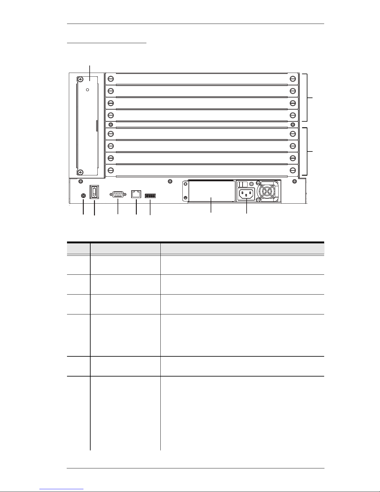
VM1600 Rear View
No. Component Description
1 Grounding Terminal The grounding wire attaches here. See Grounding,
page 21, for further details.
2 Power Switch This is a standard rocker switch that powers the unit
on and off.
3 RS-232 Serial Port Connect a computer or high-end system controller via
this serial port.
4 Ethernet Port In order to access the VM1600’s web Graphical User
Interface (GUI), the VM1600 must be connected to the
network. The cable that connects the VM1600 to your
LAN plugs in here. See Cable Connection, page 24,
for further details
5 RS-485 / RS-422
Serial Port
Connect a computer or high-end system controller via
this serial port.
6 Redundant Power
Slot (Optional)
This slot with protective cover is used to install an
additional power supply for redundant power
protection.
Note: The extra power module is not included in the
VM1600 package.See Depending on any optional
equipment that you may have purchased, one of the
following may be included in your package. Contact
your ATEN dealer to purchase any of these additional
accessories., page 8, for details.
2
3
4
5
6
1
8
7
9
10

Modular Matrix Solution User Manual
12
7 Primary Power Supply This is a standard 3-pin power socket. The power cord
from a source plugs in here.
8 Input Board Slots Unscrew the cover to insert the Input boards into these
4 horizontal slots. The source devices connect to the
inserted Input boards.
9 Output Board slots Unscrew the cover to insert the output boards into
these 4 horizontal slots. The display devices connect
to the inserted Input boards.
10 Fan Module This slot contains the fan module. The fan is hot-
pluggable and the panel unscrews to install a
replacement module. See Depending on any optional
equipment that you may have purchased, one of the
following may be included in your package. Contact
your ATEN dealer to purchase any of these additional
accessories., page 8, for details
No. Component Description
Chapter 1. Introduction
13
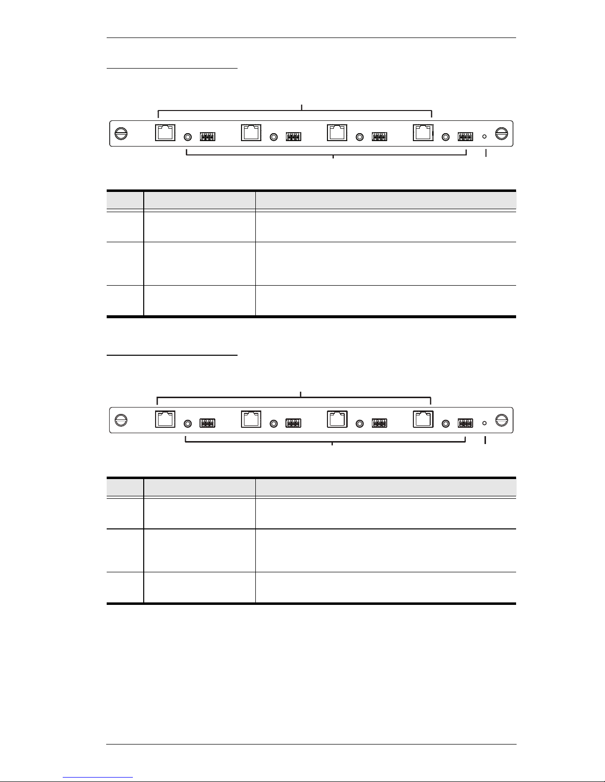
VM7514 Front View
VM8514 Front View
No. Component Description
1 HDBaseT Input Ports Connect the Cat 5e cables from your HDBaseT
transmitter to these ports.
2 IR / RS-232
Input Ports
Connect the cables from your IR transmitter to the mini
stereo jack ports, and connect the cables from your
RS-232 device to the RS-232 ports.
3 Status LED The VM7514 has an LED to indicate the working
status.
No. Component Description
1 HDBaseT Output
Ports
Connect the Cat 5e cables from your HDBaseT
receiver to these ports.
2 IR / RS-232
Output Ports
Connect the cables from your IR receiver to the mini
stereo jack ports, and connect the cables from your
RS-232 device to the RS-232 ports.
3 Status LED The VM8514 has an LED to indicate the working
status.
2
3
1
2
3
1
Modular Matrix Solution User Manual
14
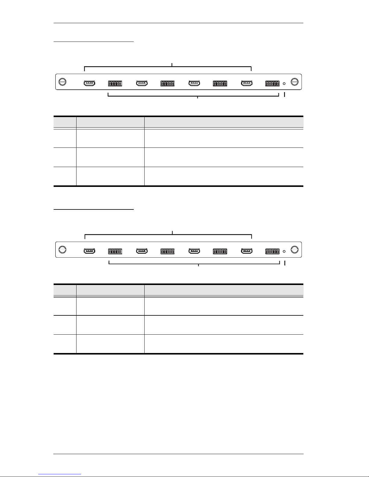
VM7804 Front View
VM8804 Front View
No. Component Description
1 HDMI Input Ports Connect the cables from your HDMI video source
devices to these ports.
2 Audio Input Ports Connect the cables from your audio source devices to
these ports.
3 Status LED The VM7804 has an LED to indicate the working
status.
No. Component Description
1 HDMI Output Ports Connect the cables from your HDMI display devices
(monitors, projectors, TVs) to these ports.
2 Audio Output Ports Connect the cables from your output audio devices or
speakers to these ports.
3 Status LED The VM8804 has an LED to indicate the working
status.
2
3
1
2
3
1
Chapter 1. Introduction
15
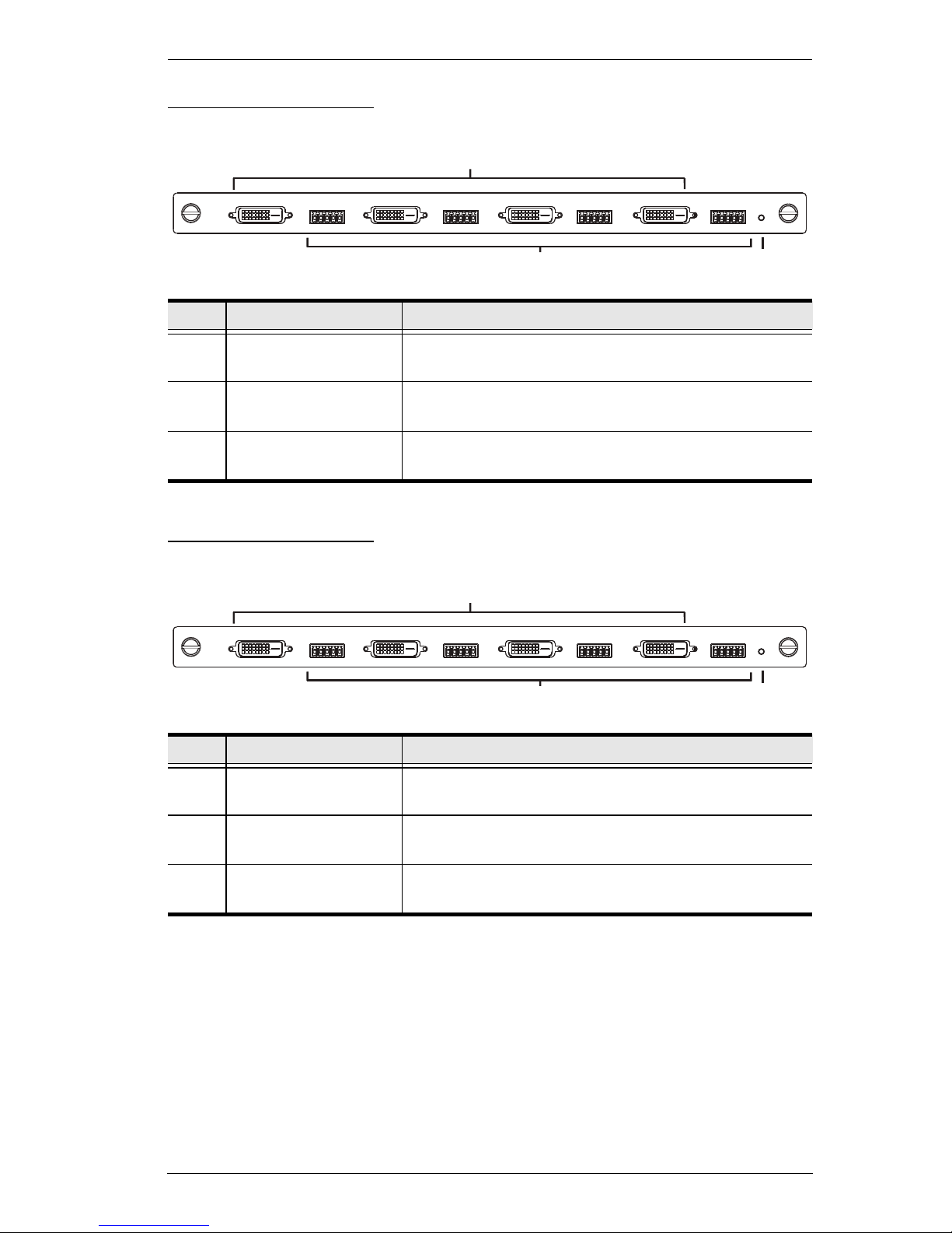
VM7604 Front View
VM8604 Front View
No. Component Description
1 DVI Input Ports Connect the cables from your video source devices to
these ports.
2 Audio Input Ports Connect the cables from your audio source devices to
these ports.
3 Status LED The VM7604 has an LED to indicate the working
status.
No. Component Description
1 DVI Output Ports Connect the cables from display devices (monitors,
projectors, TVs) to these ports.
2 Audio Output Ports Connect the cables from your output audio devices or
speakers to these ports.
3 Status LED The VM8604 has an LED to indicate the working
status.
1
2
3
1
2
3
Modular Matrix Solution User Manual
16
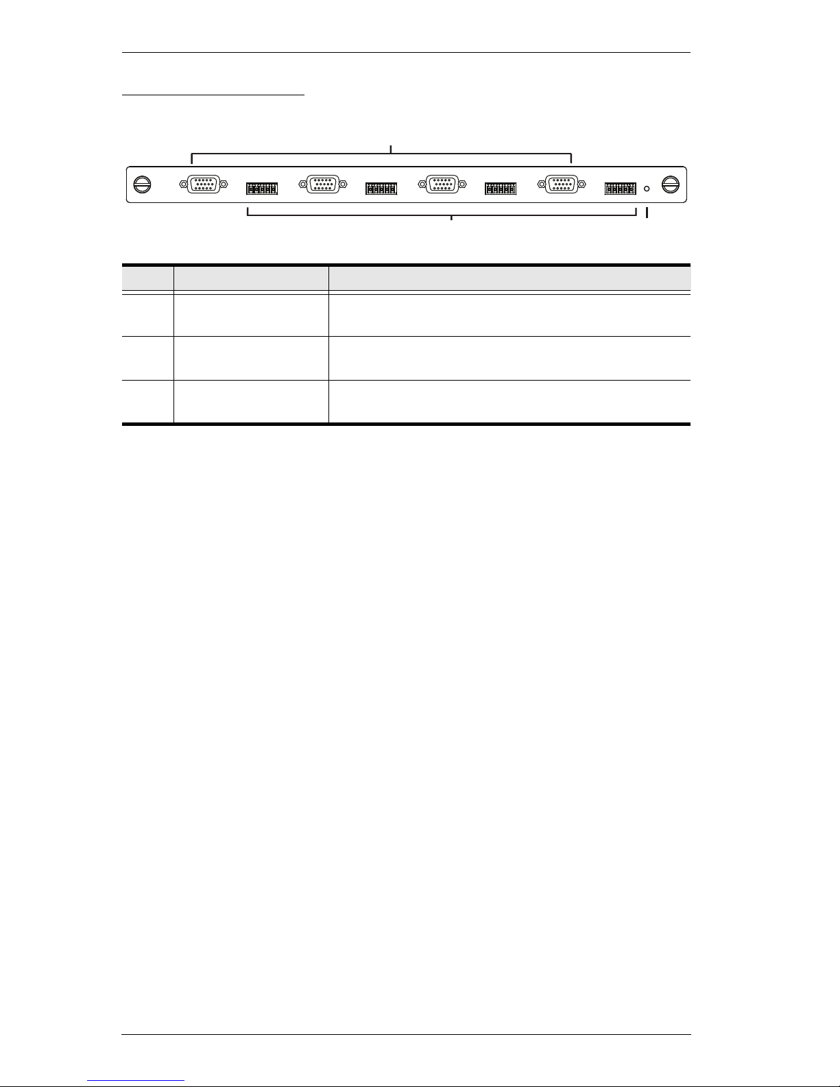
VM7104 Front View
No. Component Description
1 VGA Input Ports Connect the cables from your VGA video source
devices to these ports.
2 Audio Input Ports Connect the cables from your audio source devices to
these ports.
3 Status LED The VM7104 has an LED to indicate the working
status.
2
3
1
Chapter 1. Introduction
17
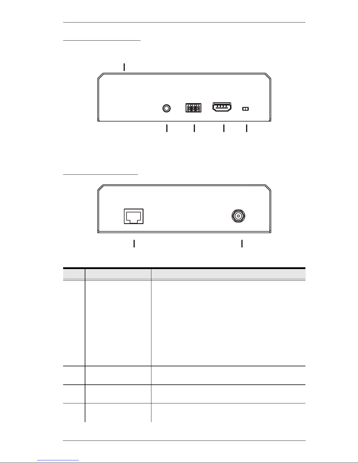
VE805R Front View
VE805R Rear View
No. Component Description
1 LEDs Three LEDs – Power, Link and HDMI Out – light when
the unit is properly connected to an appropriate
source.
Power - lights Green to indicate the unit is receiving
power.
Link - lights Orange to indicate that communication
between VE805R and output board is established.
HDMI Out - lights Orange to indicate the HDMI out-
put signal is good. LED blinks Orange every second
to indicate that the device is in F/W upgrade mode.
2 IRPort Connect the IR transmitter or receiver cable port into
this mini stereo jack port.
3 RS-232 Port Use the captive screw connectors (3 pole) to connect
the cable from your serial device into the RS-232 port.
4 HDMI Output Port Connect the cable from your HDMI display device
(monitors, projectors, TVs) into this port.
542 3
1
76

Modular Matrix Solution User Manual
18
5 Firmware Upgrade
Switch
Set this switch to OFF (left) for normal operation. Set
this switch to ON (right) and reset the unit’s power to
enter firmware upgrade mode (see page 89 for
details).
6 HDBaseT Input Use a Cat 5e cable to connect the VE805R to the
VM8514 output board.
7 Power Jack The power adapter cable plugs connects here.
No. Component Description
 Loading...