

ATEN VM6404HB User Manual
4 x 4 True 4K HDMI Matrix Switch with Scaler
VM6404HB
User Manual
www.aten.com

VM6404HB User Manual
EMC Information
FEDERAL COMMUNICATIONS COMMISSION INTERFERENCE
STATEMENT: This equipment has been tested and found to comply with the
limits for a Class A digital device, pursuant to Part 15 of the FCC Rules. These
limits are designed to provide reasonable protection against harmful
interference when the equipment is operated in a commercial environment.
This equipment generates, uses, and can radiate radio frequency energy and, if
not installed and used in accordance with the instruction manual, may cause
harmful interference to radio communications. Operation of this equipment in
a residential area is likely to cause harmful interference in which case the user
will be required to correct the interference at his own expense.
The device complies with Part 15 of the FCC Rules. Operation is subject to the
following two conditions: (1) this device may not cause harmful interference,
and (2) this device must accept any interference received, including
interference that may cause undesired operation.
FCC Caution: Any changes or modifications not expressly approved by the
party responsible for compliance could void the user's authority to operate this
equipment.
Warning: Operation of this equipment in a residential environment could
cause radio interference.
KCC Statement
유선 제품용 / A 급 기기 ( 업무용 방송 통신 기기 )
이 기기는 업무용 (A 급 ) 전자파적합기기로서 판매자 또는 사용자는 이
점을 주의하시기 바라며 , 가정 외의 지역에서 사용하는 것을 목적으로
합니다 .
RoHS
This product is RoHS compliant.
ii

VM6404HB User Manual
User Information
Online Registration
Be sure to register your product at our online support center:
International http://eservice.aten.com
Telephone Support
For telephone support, call this number:
International 886-2-8692-6959
China 86-400-810-0-810
Japan 81-3-5615-5811
Korea 82-2-467-6789
North America 1-888-999-ATEN ext 4988
1-949-428-1111
User Notice
All information, documentation, and specifications contained in this manual
are subject to change without prior notification by the manufacturer. The
manufacturer makes no representations or warranties, either expressed or
implied, with respect to the contents hereof and specifically disclaims any
warranties as to merchantability or fitness for any particular purpose. Any of
the manufacturer's software described in this manual is sold or licensed as is.
Should the programs prove defective following their purchase, the buyer (and
not the manufacturer, its distributor, or its dealer), assumes the entire cost of all
necessary servicing, repair and any incidental or consequential damages
resulting from any defect in the software.
The manufacturer of this system is not responsible for any radio and/or TV
interference caused by unauthorized modifications to this device. It is the
responsibility of the user to correct such interference.
The manufacturer is not responsible for any damage incurred in the operation
of this system if the correct operational voltage setting was not selected prior
to operation. PLEASE VERIFY THAT THE VOLTAGE SETTING IS
CORRECT BEFORE USE.
iii

VM6404HB User Manual
© Copyright 2020 ATEN® International Co., Ltd.
Manual Date: 2020-08-12
ATEN and the ATEN logo are registered trademarks of ATEN International Co., Ltd. All rights reserved.
All other brand names and trademarks are the registered property of their respective owners.
Package Contents
The VM6404HB package consists of:
1 VM6404HB 4 x 4 True 4K HDMI Matrix Switch with Scaler
1Power Cord
1 IR Remote Control
1 IR Receiver
1 Mounting Kit
1 User Instructions*
Check to make sure that all the components are present and that nothing got
damaged in shipping. If you encounter a problem, contact your dealer.
Read this manual thoroughly and follow the installation and operation
procedures carefully to prevent any damage to the unit, and/or any of the
devices connected to it.
* Features may have been added to the VM6404HB since this manual was
published. Please visit our website to download the most up-to-date version.
iv

VM6404HB User Manual
Contents
EMC Information . . . . . . . . . . . . . . . . . . . . . . . . . . . . . . . . . . . . . . . . . . . . ii
RoHS. . . . . . . . . . . . . . . . . . . . . . . . . . . . . . . . . . . . . . . . . . . . . . . . . . . . . . ii
User Information . . . . . . . . . . . . . . . . . . . . . . . . . . . . . . . . . . . . . . . . . . . . .iii
Online Registration . . . . . . . . . . . . . . . . . . . . . . . . . . . . . . . . . . . . . . . .iii
Telephone Support . . . . . . . . . . . . . . . . . . . . . . . . . . . . . . . . . . . . . . . .iii
User Notice . . . . . . . . . . . . . . . . . . . . . . . . . . . . . . . . . . . . . . . . . . . . . .iii
Package Contents . . . . . . . . . . . . . . . . . . . . . . . . . . . . . . . . . . . . . . . . . . iv
Contents . . . . . . . . . . . . . . . . . . . . . . . . . . . . . . . . . . . . . . . . . . . . . . . . . . . v
About this Manual . . . . . . . . . . . . . . . . . . . . . . . . . . . . . . . . . . . . . . . . . . ix
Conventions . . . . . . . . . . . . . . . . . . . . . . . . . . . . . . . . . . . . . . . . . . . . . . . . x
Product Information. . . . . . . . . . . . . . . . . . . . . . . . . . . . . . . . . . . . . . . . . . . x
1. Introduction
Overview . . . . . . . . . . . . . . . . . . . . . . . . . . . . . . . . . . . . . . . . . . . . . . . . . . .1
Features . . . . . . . . . . . . . . . . . . . . . . . . . . . . . . . . . . . . . . . . . . . . . . . . . . .2
Required Devices and Accessories . . . . . . . . . . . . . . . . . . . . . . . . . . . . . .3
Supported Browsers . . . . . . . . . . . . . . . . . . . . . . . . . . . . . . . . . . . . . . . . . .4
Components . . . . . . . . . . . . . . . . . . . . . . . . . . . . . . . . . . . . . . . . . . . . . . . . 5
Front View . . . . . . . . . . . . . . . . . . . . . . . . . . . . . . . . . . . . . . . . . . . . . . .5
Rear View . . . . . . . . . . . . . . . . . . . . . . . . . . . . . . . . . . . . . . . . . . . . . . .6
IR Remote Control . . . . . . . . . . . . . . . . . . . . . . . . . . . . . . . . . . . . . . . . 7
2. Hardware Setup
Rack Mounting . . . . . . . . . . . . . . . . . . . . . . . . . . . . . . . . . . . . . . . . . . . . . . 9
Cable Connection . . . . . . . . . . . . . . . . . . . . . . . . . . . . . . . . . . . . . . . . . . .10
3. Front Panel Configuration
Overview . . . . . . . . . . . . . . . . . . . . . . . . . . . . . . . . . . . . . . . . . . . . . . . . . . 11
Front Panel Pushbuttons. . . . . . . . . . . . . . . . . . . . . . . . . . . . . . . . . . . . . .11
Main Screen . . . . . . . . . . . . . . . . . . . . . . . . . . . . . . . . . . . . . . . . . . . . . . .12
Port Switching . . . . . . . . . . . . . . . . . . . . . . . . . . . . . . . . . . . . . . . . . . .12
Input Assignment . . . . . . . . . . . . . . . . . . . . . . . . . . . . . . . . . . . . . .12
Output Port Assignment. . . . . . . . . . . . . . . . . . . . . . . . . . . . . . . . .13
LCD Menu Organization . . . . . . . . . . . . . . . . . . . . . . . . . . . . . . . . . . . . . . 14
Menu Pushbutton . . . . . . . . . . . . . . . . . . . . . . . . . . . . . . . . . . . . . . . . . . . 15
IP Settings . . . . . . . . . . . . . . . . . . . . . . . . . . . . . . . . . . . . . . . . . . . . . .15
IP Address / Subnet Mask . . . . . . . . . . . . . . . . . . . . . . . . . . . . . . .15
Gateway . . . . . . . . . . . . . . . . . . . . . . . . . . . . . . . . . . . . . . . . . . . .16
v

VM6404HB User Manual
Serial Port Setting . . . . . . . . . . . . . . . . . . . . . . . . . . . . . . . . . . . . . . . 17
Baud Rate . . . . . . . . . . . . . . . . . . . . . . . . . . . . . . . . . . . . . . . . . . 17
Operation Mode . . . . . . . . . . . . . . . . . . . . . . . . . . . . . . . . . . . . . . . . . 18
EDID Mode . . . . . . . . . . . . . . . . . . . . . . . . . . . . . . . . . . . . . . . . . . 18
CEC. . . . . . . . . . . . . . . . . . . . . . . . . . . . . . . . . . . . . . . . . . . . . . . . 19
OSD. . . . . . . . . . . . . . . . . . . . . . . . . . . . . . . . . . . . . . . . . . . . . . . . 20
Video Outputs . . . . . . . . . . . . . . . . . . . . . . . . . . . . . . . . . . . . . . . . 21
Audio Extract . . . . . . . . . . . . . . . . . . . . . . . . . . . . . . . . . . . . . . . . 22
Output Resolutions . . . . . . . . . . . . . . . . . . . . . . . . . . . . . . . . . . . . 23
Security Mode . . . . . . . . . . . . . . . . . . . . . . . . . . . . . . . . . . . . . . . . . . 25
Mode . . . . . . . . . . . . . . . . . . . . . . . . . . . . . . . . . . . . . . . . . . . . . . . 25
Changing the LCD Password . . . . . . . . . . . . . . . . . . . . . . . . . . . . 26
Saving a Profile . . . . . . . . . . . . . . . . . . . . . . . . . . . . . . . . . . . . . . . . . 27
Playing/Stopping the Profile Schedule . . . . . . . . . . . . . . . . . . . . . . . . 28
Profile Configuration . . . . . . . . . . . . . . . . . . . . . . . . . . . . . . . . . . . . . . . . 29
IR Remote Control Operation . . . . . . . . . . . . . . . . . . . . . . . . . . . . . . . . . 30
Switching the Input . . . . . . . . . . . . . . . . . . . . . . . . . . . . . . . . . . . . . . . 30
Turning the Outputs on/off . . . . . . . . . . . . . . . . . . . . . . . . . . . . . . . . . 30
Turning All Outputs on/off . . . . . . . . . . . . . . . . . . . . . . . . . . . . . . . . . . 31
4. Browser Operation
Overview. . . . . . . . . . . . . . . . . . . . . . . . . . . . . . . . . . . . . . . . . . . . . . . . . . 33
Login . . . . . . . . . . . . . . . . . . . . . . . . . . . . . . . . . . . . . . . . . . . . . . . . . . . . . 33
Main Page . . . . . . . . . . . . . . . . . . . . . . . . . . . . . . . . . . . . . . . . . . . . . . . . 34
Profile List . . . . . . . . . . . . . . . . . . . . . . . . . . . . . . . . . . . . . . . . . . . . . . . . 35
Creating a Profile . . . . . . . . . . . . . . . . . . . . . . . . . . . . . . . . . . . . . . . . . . . 36
Editing a Profile . . . . . . . . . . . . . . . . . . . . . . . . . . . . . . . . . . . . . . . . . . . . 38
Editing a Profile in Normal View . . . . . . . . . . . . . . . . . . . . . . . . . . . . . 40
Profile Layout Settings . . . . . . . . . . . . . . . . . . . . . . . . . . . . . . . . . 40
Display Preferences . . . . . . . . . . . . . . . . . . . . . . . . . . . . . . . . . . . 41
Video Wall Settings . . . . . . . . . . . . . . . . . . . . . . . . . . . . . . . . . . . . 42
Editing a Profile in Grid View . . . . . . . . . . . . . . . . . . . . . . . . . . . . . . . 46
Playing a Profile . . . . . . . . . . . . . . . . . . . . . . . . . . . . . . . . . . . . . . . . . . . . 47
Input Assignment. . . . . . . . . . . . . . . . . . . . . . . . . . . . . . . . . . . . . . 49
Importing/Exporting a Profile . . . . . . . . . . . . . . . . . . . . . . . . . . . . . . . 50
Profile Scheduling . . . . . . . . . . . . . . . . . . . . . . . . . . . . . . . . . . . . . . . . . . 51
Creating the Profile Schedule . . . . . . . . . . . . . . . . . . . . . . . . . . . . . . 52
Editing the Profile Schedule . . . . . . . . . . . . . . . . . . . . . . . . . . . . . . . . 54
System Settings . . . . . . . . . . . . . . . . . . . . . . . . . . . . . . . . . . . . . . . . . . . . 56
Overview . . . . . . . . . . . . . . . . . . . . . . . . . . . . . . . . . . . . . . . . . . . . . . . 56
General . . . . . . . . . . . . . . . . . . . . . . . . . . . . . . . . . . . . . . . . . . . . . . . 58
Basics . . . . . . . . . . . . . . . . . . . . . . . . . . . . . . . . . . . . . . . . . . . . . . 58
Fan Status . . . . . . . . . . . . . . . . . . . . . . . . . . . . . . . . . . . . . . . . . . . 58
Serial Settings . . . . . . . . . . . . . . . . . . . . . . . . . . . . . . . . . . . . . . . . 58
Port Settings . . . . . . . . . . . . . . . . . . . . . . . . . . . . . . . . . . . . . . . . . . . . 59
vi

VM6404HB User Manual
OSD/CEC . . . . . . . . . . . . . . . . . . . . . . . . . . . . . . . . . . . . . . . . . . . 59
HDCP . . . . . . . . . . . . . . . . . . . . . . . . . . . . . . . . . . . . . . . . . . . . . . . . .60
Scaler. . . . . . . . . . . . . . . . . . . . . . . . . . . . . . . . . . . . . . . . . . . . . . .61
Port Name . . . . . . . . . . . . . . . . . . . . . . . . . . . . . . . . . . . . . . . . . . .62
EDID Settings . . . . . . . . . . . . . . . . . . . . . . . . . . . . . . . . . . . . . . . . . . .63
EDID Mode . . . . . . . . . . . . . . . . . . . . . . . . . . . . . . . . . . . . . . . . . .64
Customized Mode . . . . . . . . . . . . . . . . . . . . . . . . . . . . . . . . . . . . .65
EDID & CEA Description . . . . . . . . . . . . . . . . . . . . . . . . . . . . . . .67
Customized EDID Parameters . . . . . . . . . . . . . . . . . . . . . . . . . . .68
Detail Timing / Display Description . . . . . . . . . . . . . . . . . . . . . . . .70
Monitor Description . . . . . . . . . . . . . . . . . . . . . . . . . . . . . . . . . . . .71
CEA Settings . . . . . . . . . . . . . . . . . . . . . . . . . . . . . . . . . . . . . . . . 72
Video Data . . . . . . . . . . . . . . . . . . . . . . . . . . . . . . . . . . . . . . . . . . 73
Audio Data . . . . . . . . . . . . . . . . . . . . . . . . . . . . . . . . . . . . . . . . . .74
HDMI Forum Vendor Specific Block . . . . . . . . . . . . . . . . . . . . . . . 75
YCBCR 4:2:0 Video Data Block. . . . . . . . . . . . . . . . . . . . . . . . . . .76
YCBCR 4:2:0 Compatibility Map Data Block . . . . . . . . . . . . . . . .77
Status . . . . . . . . . . . . . . . . . . . . . . . . . . . . . . . . . . . . . . . . . . . . . . . . .78
Connections . . . . . . . . . . . . . . . . . . . . . . . . . . . . . . . . . . . . . . . . .78
System Information . . . . . . . . . . . . . . . . . . . . . . . . . . . . . . . . . . . . 79
Maintenance . . . . . . . . . . . . . . . . . . . . . . . . . . . . . . . . . . . . . . . . . . . .80
System Setup . . . . . . . . . . . . . . . . . . . . . . . . . . . . . . . . . . . . . . . .80
System Upgrades . . . . . . . . . . . . . . . . . . . . . . . . . . . . . . . . . . . . .80
System Backup . . . . . . . . . . . . . . . . . . . . . . . . . . . . . . . . . . . . . . .81
Restoring Default Settings . . . . . . . . . . . . . . . . . . . . . . . . . . . . . . . 81
User Account . . . . . . . . . . . . . . . . . . . . . . . . . . . . . . . . . . . . . . . . .82
Adding an User Account . . . . . . . . . . . . . . . . . . . . . . . . . . . . . . . . 83
Permission Level . . . . . . . . . . . . . . . . . . . . . . . . . . . . . . . . . . . . . .84
Network . . . . . . . . . . . . . . . . . . . . . . . . . . . . . . . . . . . . . . . . . . . . .85
5. Mobile Control
Overview . . . . . . . . . . . . . . . . . . . . . . . . . . . . . . . . . . . . . . . . . . . . . . . . . . 87
The Video Matrix Control App . . . . . . . . . . . . . . . . . . . . . . . . . . . . . . . . .88
Requirements . . . . . . . . . . . . . . . . . . . . . . . . . . . . . . . . . . . . . . . . . . .88
Installation and Connections . . . . . . . . . . . . . . . . . . . . . . . . . . . . . . . .88
The Control Interface. . . . . . . . . . . . . . . . . . . . . . . . . . . . . . . . . . . . . .89
6. CLI Commands
Overview . . . . . . . . . . . . . . . . . . . . . . . . . . . . . . . . . . . . . . . . . . . . . . . . . . 91
Connecting to the Matrix Switch via Telnet . . . . . . . . . . . . . . . . . . . . . . . .91
Connecting to the Matrix Switch via RS-232 . . . . . . . . . . . . . . . . . . . . . .92
Command Verification . . . . . . . . . . . . . . . . . . . . . . . . . . . . . . . . . . . . . . .93
Commands . . . . . . . . . . . . . . . . . . . . . . . . . . . . . . . . . . . . . . . . . . . . . . . . 93
vii

VM6404HB User Manual
Switch Port Command . . . . . . . . . . . . . . . . . . . . . . . . . . . . . . . . . . . . 93
EDID Mode Command . . . . . . . . . . . . . . . . . . . . . . . . . . . . . . . . . . . . 95
Mute Command . . . . . . . . . . . . . . . . . . . . . . . . . . . . . . . . . . . . . . . . . 96
CEC Command . . . . . . . . . . . . . . . . . . . . . . . . . . . . . . . . . . . . . . . . . 98
Scaling Command . . . . . . . . . . . . . . . . . . . . . . . . . . . . . . . . . . . . . . . 99
FrameSync Command . . . . . . . . . . . . . . . . . . . . . . . . . . . . . . . . . . . 103
Fan Speed Command . . . . . . . . . . . . . . . . . . . . . . . . . . . . . . . . . . . 104
Echo Command . . . . . . . . . . . . . . . . . . . . . . . . . . . . . . . . . . . . . . . . 105
Black Screen Command . . . . . . . . . . . . . . . . . . . . . . . . . . . . . . . . . 106
Read Command . . . . . . . . . . . . . . . . . . . . . . . . . . . . . . . . . . . . . . . . 107
Reset Command . . . . . . . . . . . . . . . . . . . . . . . . . . . . . . . . . . . . . . . . 107
Baud Rate Command . . . . . . . . . . . . . . . . . . . . . . . . . . . . . . . . . . . . 108
Save/Load Profile Command . . . . . . . . . . . . . . . . . . . . . . . . . . . . . . 109
OSD Command . . . . . . . . . . . . . . . . . . . . . . . . . . . . . . . . . . . . . . . . 110
Alert Command . . . . . . . . . . . . . . . . . . . . . . . . . . . . . . . . . . . . . . . . 111
Appendix
Safety Instructions . . . . . . . . . . . . . . . . . . . . . . . . . . . . . . . . . . . . . . . . . 113
General . . . . . . . . . . . . . . . . . . . . . . . . . . . . . . . . . . . . . . . . . . . . . . . 113
Rack Mounting . . . . . . . . . . . . . . . . . . . . . . . . . . . . . . . . . . . . . . . . . 115
Technical Support . . . . . . . . . . . . . . . . . . . . . . . . . . . . . . . . . . . . . . . . . 116
International . . . . . . . . . . . . . . . . . . . . . . . . . . . . . . . . . . . . . . . . . . . 116
Specifications . . . . . . . . . . . . . . . . . . . . . . . . . . . . . . . . . . . . . . . . . . . . . 117
Limited Warranty. . . . . . . . . . . . . . . . . . . . . . . . . . . . . . . . . . . . . . . . . . . 119
viii

VM6404HB User Manual
About this Manual
This User Manual is provided to help you get the most from your VM6404HB
system. It covers all aspects of installation, configuration and operation. An
overview of the information found in the manual is provided below.
Chapter 1 Introduction, introduces you to the VM6404HB system. Its
purpose, features and benefits are presented, and its front and back panel
components are described.
Chapter 2 Hardware Setup, describes how to set up your VM6404HB
installation.
Chapter 3 Front Panel Configuration, explains the fundamental
concepts involved in operating the VM6404HB at the local site via the front
panel LCD display using pushbuttons.
Chapter 4 Browser Operation, provides a complete description of the
VM6404HB's Browser Graphical User Interface (GUI), and how to use it to
remotely configure and operate the VM6404HB.
Chapter 5 Mobile Control, introduces you to the Video Matrix Control app
and provides details on its installation requirements.
Chapter 6 CLI Commands, provides a complete list of the serial control
protocol commands used when utilizing the RS-232 Serial Port so that an extra
source device can be utilized in the installation.
Appendix, which provides specifications and other technical information
regarding the VM6404HB.
ix

VM6404HB User Manual
Conventions
This manual uses the following conventions:
Monospaced Indicates text that you should key in.
[ ] Indicates keys you should press. For example, [Enter] means to
press the Enter key. If keys need to be chorded, they appear
together in the same bracket with a plus sign between them:
[Ctrl+Alt].
1. Numbered lists represent procedures with sequential steps.
♦ Bullet lists provide information, but do not involve sequential steps.
→ Indicates selecting the option (on a menu or dialog box, for
example), that comes next. For example, Start
open the Start menu, and then select Run.
Indicates critical information.
→ Run means to
Product Information
For information about all ATEN products and how they can help you connect
without limits, visit ATEN on the Web or contact an ATEN Authorized
Reseller. Visit ATEN on the Web for a list of locations and telephone numbers:
International http://www.aten.com
North America http://www.aten-usa.com
x

Chapter 1
Introduction
Overview
True 4K Pro AV solutions with High Dynamic Range (HDR) technology is
the trend of high-definition video that delivers the ultimate visual experience
with exceptionally sharp and vibrant video quality. ATEN’s VM6404HB True
4K HDMI Matrix Switch with Scaler is compatible with the latest True 4K
video resolutions of 4096 x 2160 / 3840 x 2160@60Hz (4:4:4) and HDR,
guaranteeing crystal-clear images across four displays.
The VM6404HB supports 4K@60Hz, HDMI 2.0, and HDCP 2.2 and features
Seamless Switch™ that employs an FPGA matrix architecture that ensures
continuous video streams, real-time control, and stable signal transmissions.
With a built-in high-performance scaler, the VM6404HB easily converts
various input resolutions into various output display resolutions, giving
viewers the best video and picture quality across all displays. The switch
integrates video wall functionality with an easy-to-use web GUI that lets you
create 8 connection profiles that can be customized into different video wall
layouts. You can also have mobile access to frequently used features
such as switching of profile and AV inputs using the Video Matrix Control
App.
The VM6404HB is an ideal solution for applications that require multiple
HDMI displays with multiple HDMI sources to be conveniently set up – such
as for stage presentations, digital classroom, video conference rooms, and any
installation that requires real-time synchronization.
1

VM6404HB User Manual
Features
4 x 4 HDMI input/output connections
Multiple Control Methods – system management via front-panel
pushbuttons, IR, RS-232 control, web GUI, and CLI commands
True 4K Resolutions – handles uncompressed video resolutions up to
4096 x 2160 / 3840 x 2160@60Hz (4:4:4)
4K Scaler – features a 4K video scaler to convert input resolutions to the
optimum display resolutions
Seamless Switch™ – features close-to-zero second switching for
continuous video streams, real-time switching, and stable signal
transmissions
Video Wall – allows you to create custom video wall layouts via intuitive
web GUI
True 4K EDID Expert – selects optimum EDID settings for smooth power-
up, high-quality display, and use of the best resolutions across different
screens
FrameSync – prevents image tearing by synchronizing the scaler output
frame rate to the input signal frame rate
Audio-enabled – HDMI audio can be extracted to stereo audio
HDMI (3D, Deep color, 4K); HDCP 2.2 compatible
Consumer Electronics Control (CEC) support
Supports free mobile control using the Video Matrix Control App
ESD protection for HDMI
Rack-mountable (1U design)
1
2
Note:
When Seamless Switch™ is enabled, 3D, Deep Color, or interlace (i.e.,
1080i) formats will not be supported. To use these formats, make sure to
disable Seamless Switch™.
Videos may not display within range when Seamless Switch™ or Video
Wall is enabled, in which case please adjust the display settings on your
device.
2

Chapter 1. Introduction
Required Devices and Accessories
Prepare the following devices and accessories before installing the
VM6404HB.
Up to 4 computers or AV devices equipped with an HDMI Type A output
connector
Note: To connect a DVI source device, use a DVI-HDMI adapter.
Display devices or receivers with an HDMI Type A input connector
Cables
1 HDMI cable for each source device
1 HDMI cable for each display device
1 Cat 5e cable
1 RS-232 serial cable
Note: No cables are included in this package. We strongly recommend that
you purchase high-quality cables of appropriate length since this
will affect the quality of the audio and video display. Contact your
dealer to purchase the correct cable sets.
3

VM6404HB User Manual
Supported Browsers
Use the recommended web browsers below to access the VM6404HB’s web
console.
OS Java Version Browser Ver sio n
Windows 10_1903 x64 1.8.0_201 x64 Edge 44.18362.1.0
Firefox 68.0 x64
Chrome 75.0.3770.100 x64
Opera 62.0.3331.43 x64
Windows 8.1 x32 1.8.0_201 IE 11
Windows 2019_1809
DataCenter x64
Windows 2016 x64 1.8.0_201 x64 IE 11 x64
Windows 7 SP1 x64 1.8.0_201 x64 IE 11 x64
CentOS 7.5 x64 Kernel
4.18.11-1
Ubuntu 18.04 x64 Kernel
4.19.041900rc3
Solaris 11.4 x64 5.11 1.8.0.181 x64 Firefox 52.9.0 x32
MAC 11.4 - Safari 8
Windows 10 x64 1.8.0_201 x64 QQ 10.4.3587.400.
Windows 10 x64 1.8.0_201 x64 360 10.0.1508.0
1.8.0_201 x64 IE 11 x64
1.8.0_201 x64 Firefox 60.7.2-1 x64
1.8.0_201 x64 Chrome 75.0.3770.100-1 x64
4
Chapter 1. Introduction
112
2
3
3
4
4
1 2 54
3
Components
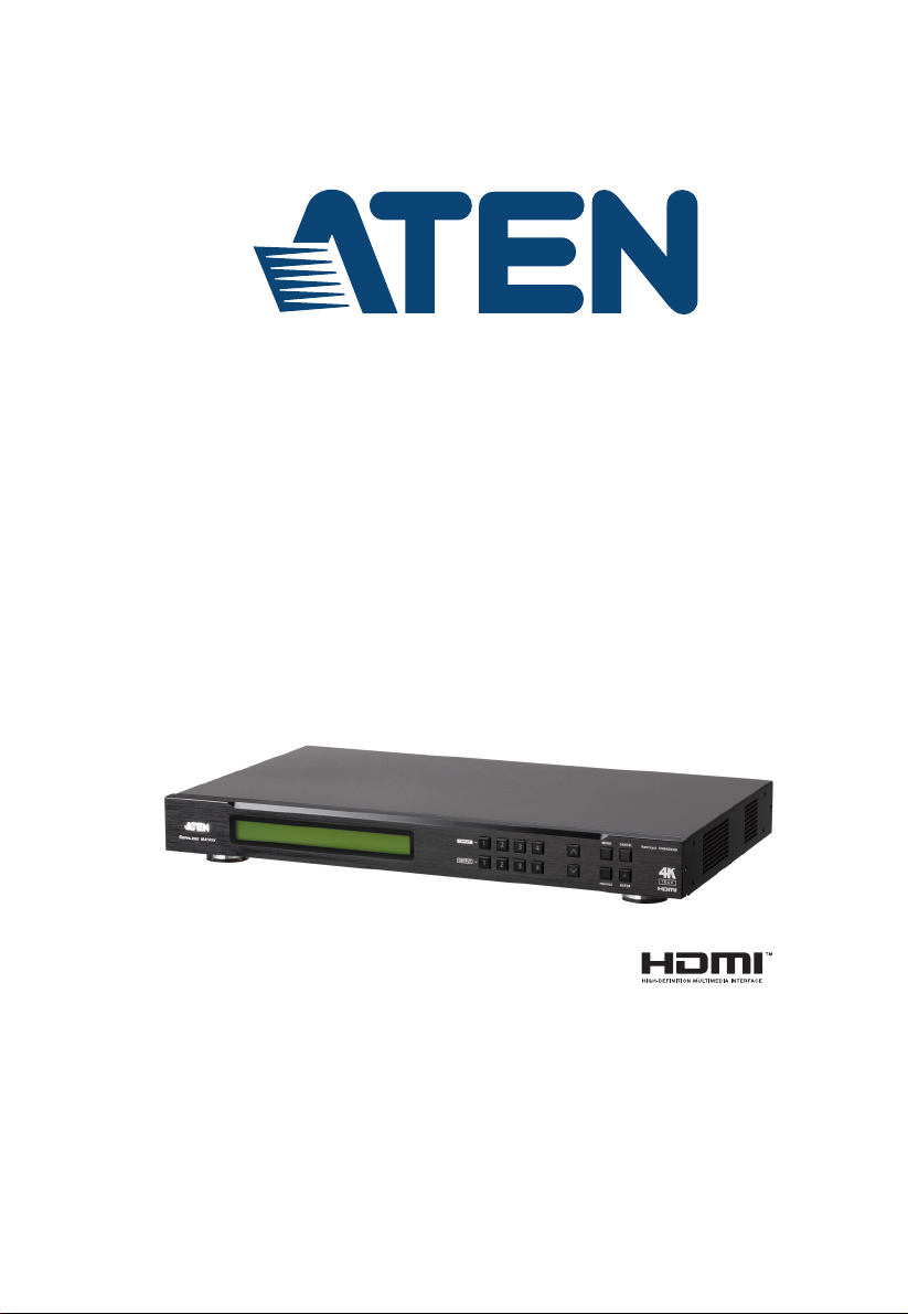
Front View
No. Component Description
1 LCD Display The LCD Display gives a quick view of all port connections,
and shows the various options for configuring and operating
the VM6404HB. For full details, see Main Screen, page 12.
2 Input
Pushbuttons
3 Output
Pushbuttons
4Prev / Next
Pushbuttons
5 Function
Pushbuttons
These pushbuttons refer to the HDMI Input ports found on
the VM6404HB rear panel. Press to select the Input port.
These pushbuttons may also correspond to menu options,
connection profiles (P1–P4) and so on.
Note: The INPUT (1–4) front panel pushbuttons have built-in
LEDs that light to indicate they have been selected.
These pushbuttons refer to the HDMI Output ports found on
the VM6404HB rear panel. Press to select the Output port.
These pushbuttons may also correspond to connection
profiles (P5–P8).
Note: The OUTPUT (1–4) front panel pushbuttons have
built-in LEDs that light to indicate they have been selected.
These pushbuttons allow you to cycle through the menu
options on the LCD display.
The function pushbuttons (MENU, PROFILE, ENTER and
CANCEL) are for navigating the LCD built-in configuration
utility. For full details, see Front Panel Pushbuttons, page 11.
Note: The MENU and PROFILE front panel pushbuttons
have built-in LEDs that light to indicate they have been
selected.
5
VM6404HB User Manual
6
4
3 7
1 2 98
5
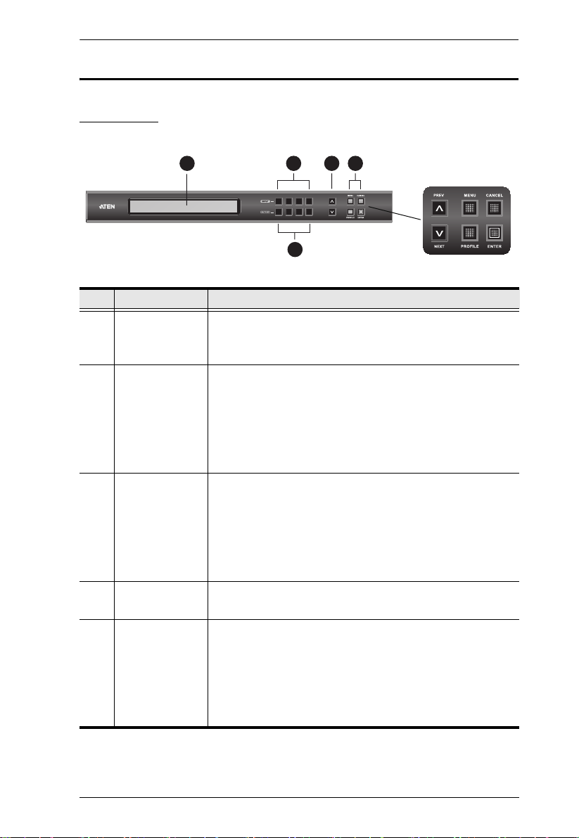
Rear View
No. Component Description
1 Power Socket This is a standard 3-pin AC power socket. The power
cord from an AC source plugs in here.
2 Power Switch This is a standard rocker switch that powers the unit on
and off.
3 Grounding Terminal The grounding wire attaches here.
4 HDMI Output Ports The cables from your HDMI display devices plug into
these ports.
5 HDMI Input Ports The cables from your HDMI source devices plug into
these ports.
6 Stereo Audio Output Connect an audio output device into this port.
7 IR Port Connect the IR Receiver unit included with your product
via this 3.5 mm Mini Stereo Jack.
8 Ethernet Port In order to access the VM6404HB’s Browser Graphical
User Interface (GUI), the VM6404HB must be connected
to your network. The cable that connects the VM6404HB
to your LAN plugs in here. See Cable Connection,
page 10, for further details.
9 RS-232 Serial Port Connect a computer or high-end system controller via
this serial port.
6
Chapter 1. Introduction
1
2
3
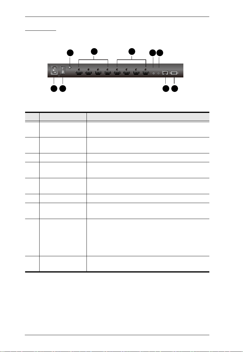
IR Remote Control
No. Component Description
1 Power ON/OFF Use the ON and OFF pushbuttons to turn the Output
displays on or off – by individual port, or all ports. (see IR
Remote Control Operation, page 30)
2 Output Pushbuttons
1–4
3 Input Pushbuttons
1–4
Press Output display pushbuttons 1–4 to select the Output
display you want to configure (see IR Remote Control
Operation, page 30).
Press Input source pushbuttons 1–4 to select the Input
source you want to display on a selected output (see IR
Remote Control Operation, page 30).
Note: The Input and Output pushbuttons 5–8 are not functional.
7

VM6404HB User Manual
This Page Intentionally Left Blank
8
Chapter 2
1. Important safety information regarding the placement of this
device is provided on page 113. Please review it before
proceeding.
2. Make sure that the power to all devices connected to the
installation are turned off. You must unplug the power cords of
any computers that have the Keyboard Power On function.
Hardware Setup
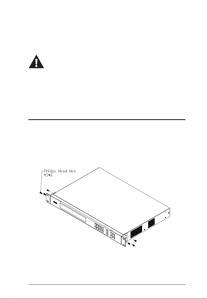
Rack Mounting
The VM6404HB can be mounted in a 19” (1U) system rack. For the most
convenient front panel pushbutton configuration and operation at the local site,
mount the unit at the front of the rack, as follows:
1. Use the six M3 x 6 Phillips head hex screws supplied with the Mounting
Kit to secure the rack mounting brackets onto the front of the unit.
2. Position the unit in the front of the rack and align the holes in the mounting
brackets with the holes in the rack.
3. Screw the mounting brackets to the rack.
9
VM6404HB User Manual
4
2
3
8 9 1
6
5
Display Devices
Source Devices
Speaker IR Receiver
RS-232
Controller
Internet
LAN
7
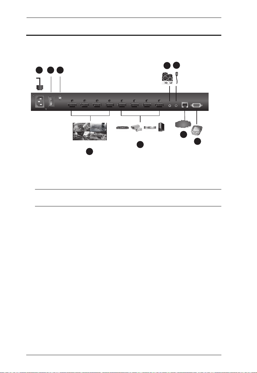
Cable Connection
Follow the steps below to safely connect the required devices to the
VM6404HB.
1. Use a grounding wire to ground the unit by connecting one end of the wire
to the grounding terminal, and the other end to a suitable grounded object.
Also make sure to properly ground all devices in the installation.
Note: Do not omit this step. Proper grounding helps prevent damage to the
unit from surges or static electricity.
2. Connect up to 4 HDMI-enabled video sources to the HDMI Input ports.
3. Connect up to 4 HDMI-enabled display devices to the HDMI Output
ports.
4. To access system settings via the web GUI or to remotely control the
VM6404HB using the Mobile Control App, use an Ethernet cable to
connect the Ethernet port of the unit to a network switch.
5. (Optional) To extract HDMI audio, connect a speaker to the Stereo Audio
Out port.
6. (Optional) To operate the VM6404HB using an IR remote control, connect
the supplied IR receiver to the IR Receiver Port.
7. (Optional) To configure the unit’s settings via an RS-232 interface,
connect a hardware or software controller to the RS-232 Serial Port.
8. Plug the power cord to the Power Socket.
9. Put the Power Switch to ON.
10. Power on all the connected devices.
10

Chapter 3
Front Panel Configuration
Overview
This chapter provides detailed information on operating the VM6404HB using
the panel pushbuttons and IR remote controller.
Front Panel Pushbuttons
The front panel features an LCD display and pushbuttons for convenient
operation locally. This allows users to perform operations such as selecting
which source shows on which display, viewing the system network settings,
configuring the serial port, setting the EDID Mode / CEC / OSD / Output
Status, selecting security settings, and loading/saving profiles.
Note the following front panel pushbutton functions:
Use the MENU pushbutton to access the Menu page options: IP Setting,
Serial Port Setting, Operation Mode, Security Mode, Save to a Profile,
Play the Profile Schedule. For more information, see LCD Menu
Organization, page 14
Use the PROFILE pushbutton to switch between connection profiles
which have been created via the web GUI. Pressing this pushbutton for
longer than 3 seconds displays the Save to a Profile page (see Saving a
Profile, page 27).
Use the CANCEL pushbutton to go back to a previous page, return to the
Main Screen, stop or exit an operation.
Use the ENTER pushbutton to select options and confirm operations.
Use the INPUT (1-4) / OUTPUT (1-4) pushbuttons to select the Input/
Output port. These pushbuttons may also correspond to menu options,
connection profiles, and so on.
Use the Prev / Next pushbuttons to navigate the menus.
11
VM6404HB User Manual
INPUT 1 2 3 4
OUTPUT 1 2 3 4
P1
INPUT 1 2 3 4
OUTPUT 1 2 3 4
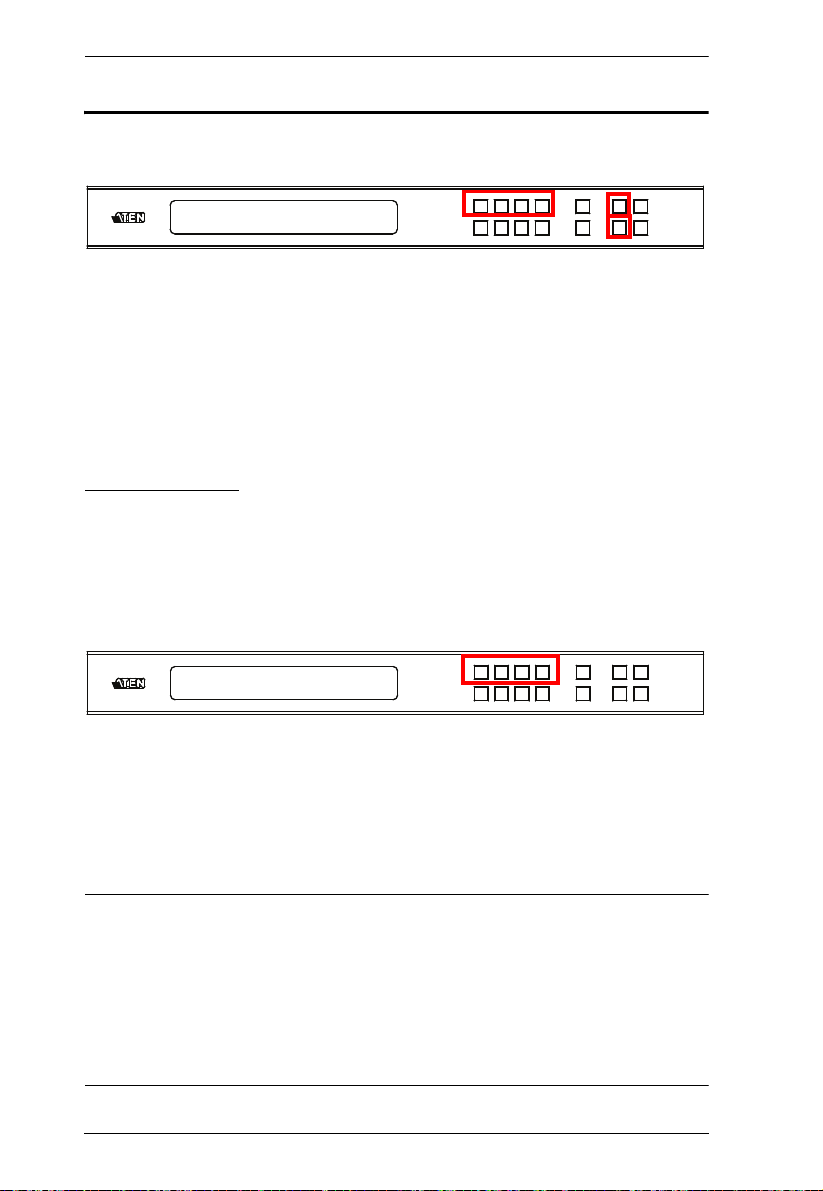
Main Screen
The Main Screen shows the Input ports (1-4) in the top row, which are tied to
the Output ports shown in sequential order (1-4) at the bottom row.
The front panel pushbutton label corresponds to the Input ports (1-4) and
Output ports (1-4) on the unit’s rear panel.
Use the Menu pushbutton to view the LCD Menu (see LCD Menu
Organization, page 14).
Use the Profile pushbutton to switch between profile connections (see
Profile List, page 35).
Port Switching
From the Main Screen, users can configure the input-to-output port
connections to associate an Input source device to an Output display.
Input Assignment
Use the Input pushbuttons to select the input you want to configure.
To assign an input to one or more output displays, do the following:
1. Press an Input pushbutton. The outputs already assigned with this input
light blue.
2. To assign this input to more outputs, press the Output pushbutton. To deselect an output, press the pushbutton again.
Note:
Input ports that are not assigned to any output will not be shown in the
LCD screen.
Pressing the Cancel pushbutton once stops the Input Port Selection
operation and the LCD displays the active setting. Pressing the Cancel
pushbutton again turns all LEDs off.
After 10 seconds of inactivity, all the LEDs turn off.
12
Chapter 3. Front Panel Configuration
INPUT 1 2 3 4
OUTPUT 1 2 3 4
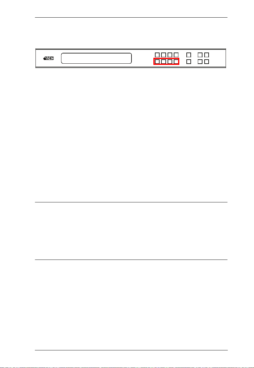
Output Port Assignment
Use the Output pushbuttons to select the Output port you want to configure.
To assign an input to one output, do the following:
1. Press any Output pushbuttonn. The input assigned to this output lights
yellow.
2. To assign another input to this output port, press the Input pushbutton. The
pushbutton of the assigned input lights yellow.
If an Output pushbutton is pressed a second time, it is deselected and the
LED turns off.
To assign an input to multiple outputs, do the following:
1. Press the pushbuttons for the outputs to which you wish to assign a
common input. These Output pushbuttons light blue.
2. Press an Input pushbutton to assign the input to the outputs you selected in
step 1.
Note:
To deselect an output, press the pushbutton again. The pushbutton dims.
Pressing the Cancel pushbutton once stops the Output Port Selection
operation and the LCD displays the active setting. Pressing the Cancel
pushbutton again turns all LEDs off.
After 10 seconds of inactivity, all the LEDs turn off.
13
VM6404HB User Manual
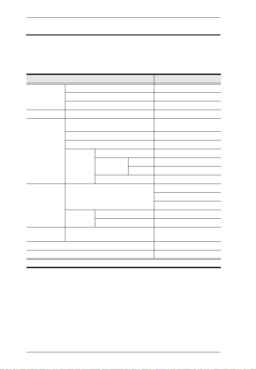
LCD Menu Organization
The VM6404HB has a built-in configuration utility via the front panel LCD,
which can be controlled by pressing the MENU and Input pushbuttons. User
can cycle through the menu options, starting from IP Setting page, in the order
shown in the table below:
LCD Menu Options
IP Setting IP Address -
Subnet Mask -
Gateway -
Serial Port Setting Baud Rate 9600 / 19200 / 38400 / 115200
Operation Mode EDID Default / Port1 / Remix /
CEC On / NA
OSD On / NA
Output Status Video On / NA
Audio Extract Audio Input 01-04
Mute On / NA
Output Resolutions 01-04
Security Mode Mode None
Change
Password
Save to a Profile Save to a Profile No. Input pushbutton: 01–04
Play/Stop the Profile Schedule -
Break Output Group -
Note: Default settings are indicated in bold.
Old Password -
New Password -
Customized
Password Enable
Lock Screen
output pushbutton: 05-08
14
Chapter 3. Front Panel Configuration
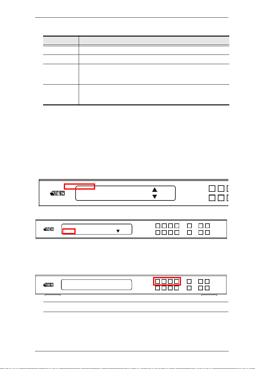
1: IP Setting
2: Serial Port Setting
: Next
IP Address: 192.168.0.60
Subnet Mask: 255.255.255.0
: Next
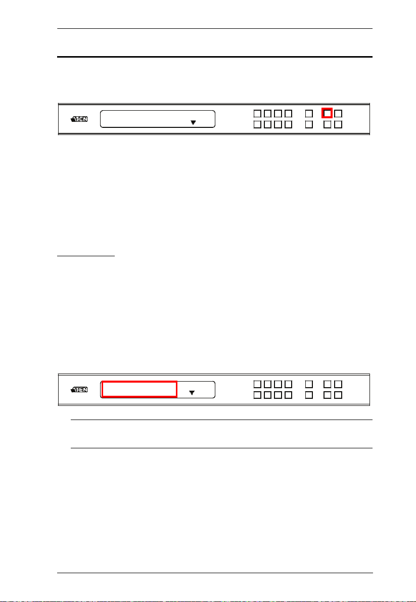
Menu Pushbutton
Press the MENU pushbutton to switch between the Main Screen and LCD
Menu page. When the Menu is active, the MENU pushbutton lights up:
From the Menu page:
Press 1 to go to the IP Setting page (see IP Settings, page 15)
Press 2 to go to the Serial Port Setting page (see Serial Port Setting,
page 17)
Press Next to go to the next page(s) for the sub-menu pages
Press Menu to return to the Main Screen
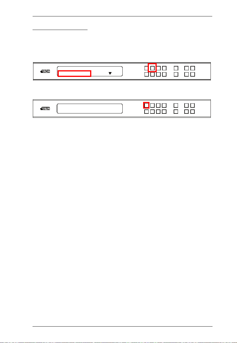
IP Settings
The IP Setting page displays the VM6404HB’s IP configuration. These
settings are read-only in the LCD Menu and can be configured via the Web
GUI.
IP Address / Subnet Mask
To view the VM6404HB’s IP address and Subnet Mask, do the following:
1. Press the Menu pushbutton, and then press Input pushbutton 1 to see the
IP Setting submenu. The IP address and Subnet Mask are then shown.
Note: The VM6404HB’s default IP address is 192.168.0.60. The default
Subnet Mask is 255.255.255.0
2. Press Next to go to the next page.
3. Press Menu to return to the Menu page.
4. Press Cancel to return to the previous page without saving.
15

VM6404HB User Manual
Gateway: 192.168.0.1
: Prev
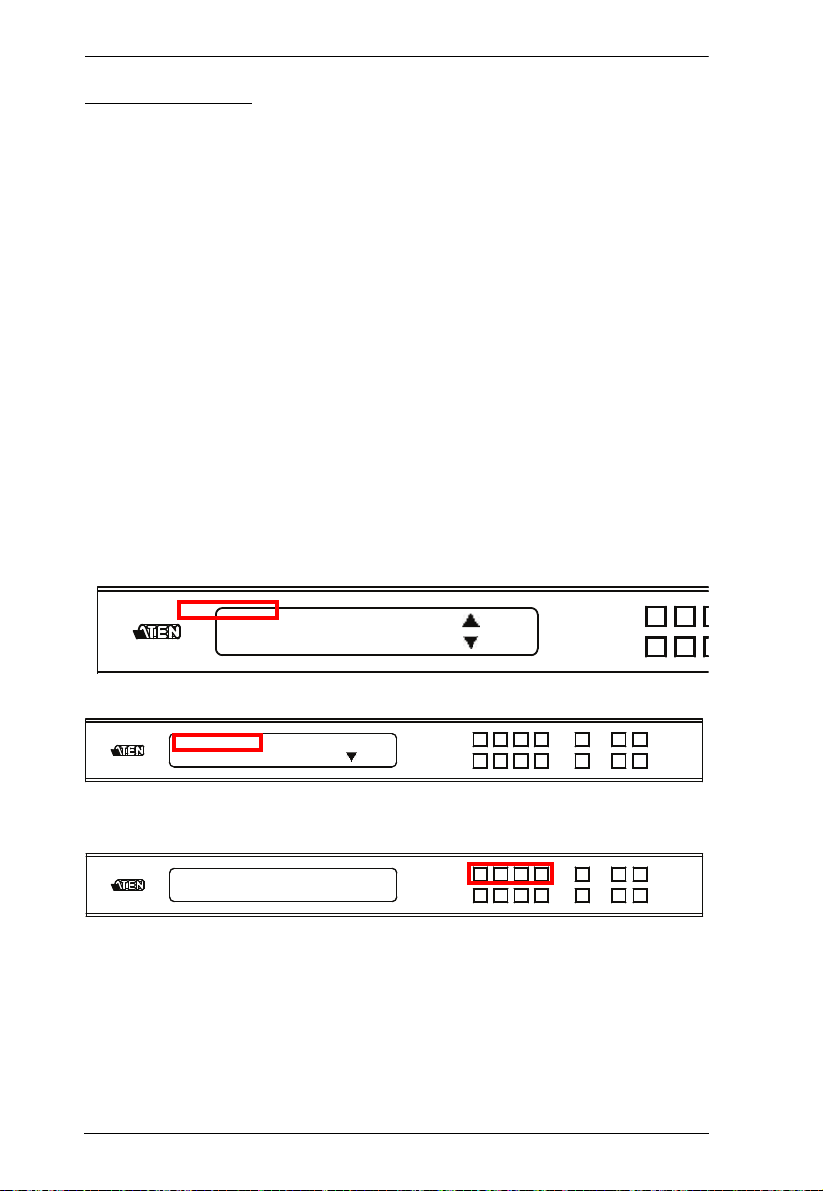
Gateway
To view the VM6404HB’s gateway address, do the following:
1. Press the Menu pushbutton, press Input pushbutton 1 to see the IP
Setting submenu, then press Next to get to the next page. The gateway
address displays.
Note: The default Gateway is 192.168.0.1.
2. Press
Prev to go to the previous page.
3. Press Menu to return to the Menu page.
4. Press Cancel to go back a level, return to the initial screen, or exit.
16
Chapter 3. Front Panel Configuration
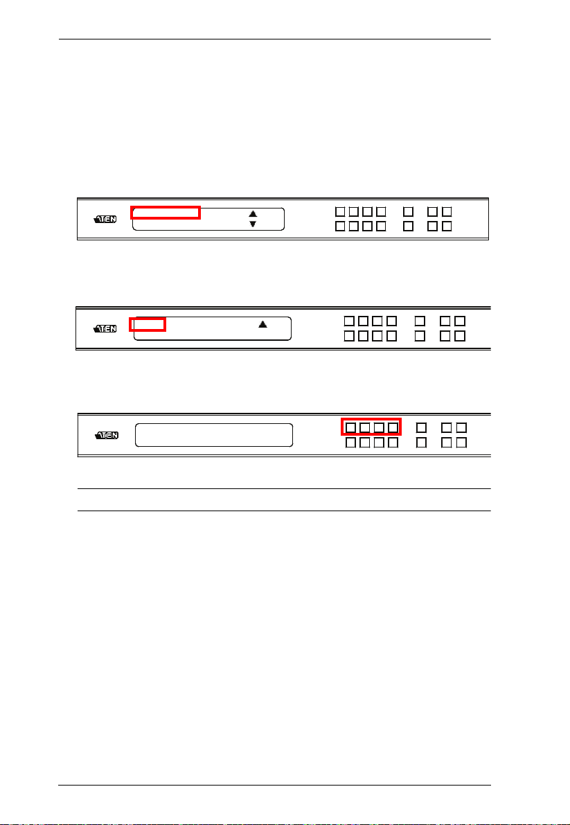
1: IP Setting
2: Serial Port Setting
: Next
Serial Port Setting
Baud Rate
To set the VM6404HB’s baud rate, do the following:
1. Press the Menu pushbutton, and then press Input pushbutton 2.
2. Press Input pushbutton 1 to select Baud Rate Setting.
1: Baud Rate Setting
3. Press Menu to return to the Menu page.
4. Press Cancel to go back a level, return to the initial screen, or exit.
17
VM6404HB User Manual
1: Operation Mode
2: Security Mode
: Next
: Prev
1: EDID Mode
2: CEC
: Next
1: Port 1 3: Remix
2: Default (In use) 4: Customized
Operation Mode
The EDID Mode, CEC, OSD and Output Status features can be configured
from the Operation Mode page.
EDID Mode: The EDID (Extended Display Identification Data) mode is
used to have the VM6404HB automatically apply a preset EDID mode,
which utilizes the best resolution across different monitors
CEC: Consumer Electronics Control (CEC) allows interconnected HDMI
devices to communicate and respond to one remote control
OSD: Use this option to enable real-time port switching information for
each port.
Output Status: The Output Status shows whether the video/audio of an
Output port is turned on or off and allows viewing and setting of the
Output Resolution
EDID Mode
To configure the EDID Mode, do the following:
1. Press the Menu pushbutton, press Next, and then press Input
pushbutton 1.
2. From the Operation Mode page, press Input pushbutton 1.
3. Press Input pushbuttons 1–4 to make your selection.
18
Chapter 3. Front Panel Configuration
1: Operation Mode
2: Security Mode
: Next
: Prev
1: EDID Mode
2: CEC
: Next
OUTPUT 1 2 3 4
NA ON ON NA
EDID Mode options are:
EDID Option Description
1: Default The default EDID is passed to all video sources.
2: Port 1 The EDID from port1 is passed to all video sources.
3: Remix Uses the EDID of each connected display according to its
4: Customized This mode features an EDID Wizard that allows user-defined EDID
connection when the VM6404HB is first powered on, or
immediately after pressing 3 to select the Remix option.
configurations for optimum output. See Customized EDID
Parameters, page 68.
4. Press Menu to return to the Menu page.
5. Press Cancel to go back a level, return to the initial screen, or exit.
CEC
To configure the CEC setting, do the following:
1. Press the Menu pushbutton, press Next, and then press Input
pushbutton 1.
2. From the Operation Mode page, press Input pushbutton 2:
3. Press Input pushbuttons (1-4) to enable (ON) or disable (NA) the CEC
feature for the output port. If the port does not support CEC, an NA is
shown.
Note: The default CEC setting is NA.
4. Press Menu to return to the Menu page.
5. Press Cancel to go back a level, return to the initial screen, or exit.
19
VM6404HB User Manual
1: Operation Mode
2: Security Mode
:
Next
:
Prev
1: OSD
2: Output Status
: Prev
OUTPUT 1 2 3 4
ON ON ON NA
OSD
The On-Screen Display or OSD feature enables real-time port assignment
information to be displayed on the output screen when the assigned input
changes for the output.
To configure the OSD setting for each output port, do the following:
1. Press the Menu pushbutton, press Next, and then press Input pushbutton
1.
2. From the Operation Mode page, Next to go to the next page, then press
Input pushbutton 1:
3. Press input pushbuttons (1-4) to enable (ON) or disable (NA) the OSD
feature for the output port.
Note: The default OSD setting is On.
4. Press Menu to return to the Menu page.
5. Press Cancel to go back a level, return to the initial screen, or exit.
20
 Loading...