

4 x 4 4K HDMI Matrix Switch with Scaler
VM6404H
User Manual
www.aten.com

VM6404H User Manual
ii
EMC Information
FEDERAL COMMUNICATIONS COMMISSION INTERFERENCE
STATEMENT: This equipment has been tested and found to comply with the
limits for a Class A digital device, pursuant to Part 15 of the FCC Rules. These
limits are designed to provide reasonable protection against harmful
interference when the equipment is operated in a commercial environment.
This equipment generates, uses, and can radiate radio frequency energy and, if
not installed and used in accordance with the instruction manual, may cause
harmful interference to radio communications. Operation of this equipment in
a residential area is likely to cause harmful interference in which case the user
will be required to correct the interference at his own expense.
The device complies with Part 15 of the FCC Rules. Operation is subject to the
following two conditions: (1) this device may not cause harmful interference,
and (2) this device must accept any interference received, including
interference that may cause undesired operation.
FCC Caution: Any changes or modifications not expressly approved by the
party responsible for compliance could void the user's authority to operate this
equipment.
CE Warning: This is a class A product. In a domestic environment this
product may cause radio interference in which case the user may be required to
take adequate measures.
KCC Statement
유선 제품용 / A 급 기기 ( 업무용 방송 통신 기기 )
이 기기는 업무용 (A 급 ) 전자파적합기기로서 판매자 또는 사용자는 이
점을 주의하시기 바라며 , 가정 외의 지역에서 사용하는 것을 목적으로
합니다 .
RoHS
This product is RoHS compliant.
VM6404H User Manual
iii
Safety
This product has been classified as Information Technology Equipment.
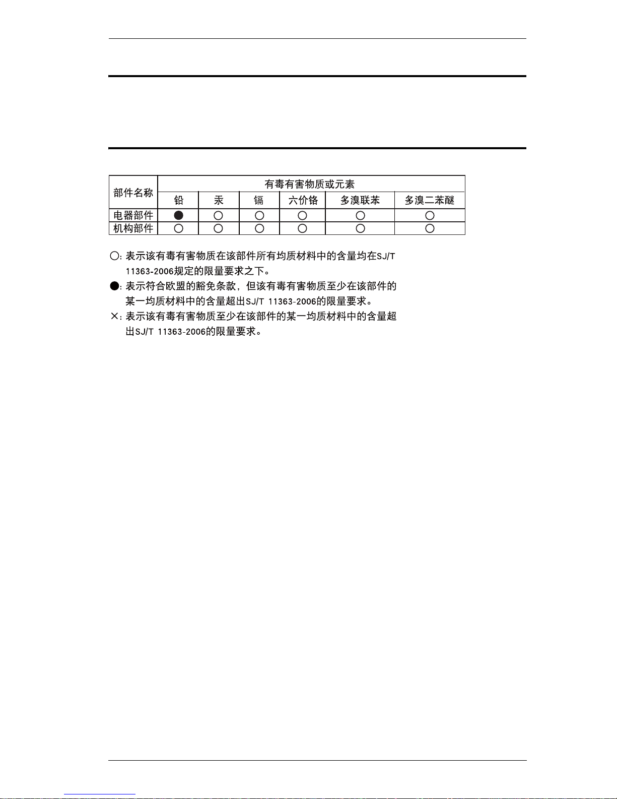
SJ/T 11364-2006
The following contains information that relates to China.

VM6404H User Manual
iv
User Information
Online Registration
Be sure to register your product at our online support center:
Telephone Support
For telephone support, call this number:
User Notice
All information, documentation, and specifications contained in this manual
are subject to change without prior notification by the manufacturer. The
manufacturer makes no representations or warranties, either expressed or
implied, with respect to the contents hereof and specifically disclaims any
warranties as to merchantability or fitness for any particular purpose. Any of
the manufacturer's software described in this manual is sold or licensed as is.
Should the programs prove defective following their purchase, the buyer (and
not the manufacturer, its distributor, or its dealer), assumes the entire cost of all
necessary servicing, repair and any incidental or consequential damages
resulting from any defect in the software.
The manufacturer of this system is not responsible for any radio and/or TV
interference caused by unauthorized modifications to this device. It is the
responsibility of the user to correct such interference.
The manufacturer is not responsible for any damage incurred in the operation
of this system if the correct operational voltage setting was not selected prior
to operation. PLEASE VERIFY THAT THE VOLTAGE SETTING IS
CORRECT BEFORE USE.
International http://eservice.aten.com
International 886-2-8692-6959
China 86-10-5255-0110
Japan 81-3-5615-5811
Korea 82-2-467-6789
North America 1-488-999-ATEN ext 4988
United Kingdom 44-8-4481-58923

VM6404H User Manual
v
Package Contents
The VM6404H package consists of:
1 VM6404H 4 x 4 4K HDMI Matrix Switch with Scaler
1Power Cord
1 IR Remote Control
1 IR Receiver
1 Mounting Kit
1 User Instructions*
Check to make sure that all the components are present and that nothing got
damaged in shipping. If you encounter a problem, contact your dealer.
Read this manual thoroughly and follow the installation and operation
procedures carefully to prevent any damage to the unit, and/or any of the
devices connected to it.
* Features may have been added to the VM6404H since this manual was
published. Please visit our website to download the most up-to-date version.
© Copyright 2015 ATEN® International Co., Ltd.
Manual Date: 2015-04-30
ATEN and the ATEN logo are registered trademarks of ATEN International Co., Ltd. All rights reserved.
All other brand names and trademarks are the registered property of their respective owners.

VM6404H User Manual
vi
Contents
EMC Information. . . . . . . . . . . . . . . . . . . . . . . . . . . . . . . . . . . . . . . . . . . . . ii
RoHS . . . . . . . . . . . . . . . . . . . . . . . . . . . . . . . . . . . . . . . . . . . . . . . . . . . . . ii
Safety . . . . . . . . . . . . . . . . . . . . . . . . . . . . . . . . . . . . . . . . . . . . . . . . . . . . .iii
SJ/T 11364-2006 . . . . . . . . . . . . . . . . . . . . . . . . . . . . . . . . . . . . . . . . . . . .iii
User Information . . . . . . . . . . . . . . . . . . . . . . . . . . . . . . . . . . . . . . . . . . . . .iv
Online Registration . . . . . . . . . . . . . . . . . . . . . . . . . . . . . . . . . . . . . . . .iv
Telephone Support . . . . . . . . . . . . . . . . . . . . . . . . . . . . . . . . . . . . . . . .iv
User Notice . . . . . . . . . . . . . . . . . . . . . . . . . . . . . . . . . . . . . . . . . . . . . .iv
Package Contents . . . . . . . . . . . . . . . . . . . . . . . . . . . . . . . . . . . . . . . . . . . v
Contents . . . . . . . . . . . . . . . . . . . . . . . . . . . . . . . . . . . . . . . . . . . . . . . . . . .vi
About this Manual . . . . . . . . . . . . . . . . . . . . . . . . . . . . . . . . . . . . . . . . . . . . x
Conventions . . . . . . . . . . . . . . . . . . . . . . . . . . . . . . . . . . . . . . . . . . . . . . . .xi
Product Information . . . . . . . . . . . . . . . . . . . . . . . . . . . . . . . . . . . . . . . . . .xi
Chapter 1.
Introduction
Overview. . . . . . . . . . . . . . . . . . . . . . . . . . . . . . . . . . . . . . . . . . . . . . . . . . . 1
Features . . . . . . . . . . . . . . . . . . . . . . . . . . . . . . . . . . . . . . . . . . . . . . . . . . . 2
Requirements . . . . . . . . . . . . . . . . . . . . . . . . . . . . . . . . . . . . . . . . . . . . . . . 3
Source Devices. . . . . . . . . . . . . . . . . . . . . . . . . . . . . . . . . . . . . . . . . . . 3
Display Devices. . . . . . . . . . . . . . . . . . . . . . . . . . . . . . . . . . . . . . . . . . . 3
Cables . . . . . . . . . . . . . . . . . . . . . . . . . . . . . . . . . . . . . . . . . . . . . . . . . . 3
Source Device Operating Systems . . . . . . . . . . . . . . . . . . . . . . . . . . . . 4
Components . . . . . . . . . . . . . . . . . . . . . . . . . . . . . . . . . . . . . . . . . . . . . . . . 5
VM6404H Front View . . . . . . . . . . . . . . . . . . . . . . . . . . . . . . . . . . . . . . 5
VM6404H Rear View. . . . . . . . . . . . . . . . . . . . . . . . . . . . . . . . . . . . . . . 6
IR Remote Control . . . . . . . . . . . . . . . . . . . . . . . . . . . . . . . . . . . . . . . . 7
Chapter 2.
Hardware Setup
Rack Mounting . . . . . . . . . . . . . . . . . . . . . . . . . . . . . . . . . . . . . . . . . . . . . . 9
Grounding . . . . . . . . . . . . . . . . . . . . . . . . . . . . . . . . . . . . . . . . . . . . . . . . . 10
Cable Connection . . . . . . . . . . . . . . . . . . . . . . . . . . . . . . . . . . . . . . . . . . . 11
Installation Diagram . . . . . . . . . . . . . . . . . . . . . . . . . . . . . . . . . . . . . . 12
Chapter 3.
Front Panel Configuration
Overview. . . . . . . . . . . . . . . . . . . . . . . . . . . . . . . . . . . . . . . . . . . . . . . . . . 13
Front Panel Pushbuttons . . . . . . . . . . . . . . . . . . . . . . . . . . . . . . . . . . . . . 13
Enter Password . . . . . . . . . . . . . . . . . . . . . . . . . . . . . . . . . . . . . . . . . . . . 14
Main Screen . . . . . . . . . . . . . . . . . . . . . . . . . . . . . . . . . . . . . . . . . . . . . . . 15
Port Switching . . . . . . . . . . . . . . . . . . . . . . . . . . . . . . . . . . . . . . . . . . . 15

VM6404H User Manual
vii
Input Port Selection . . . . . . . . . . . . . . . . . . . . . . . . . . . . . . . . . . . .15
Output Port Selection. . . . . . . . . . . . . . . . . . . . . . . . . . . . . . . . . . .17
LCD Menu Organization . . . . . . . . . . . . . . . . . . . . . . . . . . . . . . . . . . . . . .19
Menu Pushbutton . . . . . . . . . . . . . . . . . . . . . . . . . . . . . . . . . . . . . . . . . . .19
IP Setting. . . . . . . . . . . . . . . . . . . . . . . . . . . . . . . . . . . . . . . . . . . . . . . 20
IP Address / Subnet Mask . . . . . . . . . . . . . . . . . . . . . . . . . . . . . . . 20
Gateway. . . . . . . . . . . . . . . . . . . . . . . . . . . . . . . . . . . . . . . . . . . . . 20
Serial Port Setting . . . . . . . . . . . . . . . . . . . . . . . . . . . . . . . . . . . . . . . .21
Baud Rate . . . . . . . . . . . . . . . . . . . . . . . . . . . . . . . . . . . . . . . . . . . 21
Operation Mode. . . . . . . . . . . . . . . . . . . . . . . . . . . . . . . . . . . . . . . . . .22
EDID Mode . . . . . . . . . . . . . . . . . . . . . . . . . . . . . . . . . . . . . . . . . .22
CEC . . . . . . . . . . . . . . . . . . . . . . . . . . . . . . . . . . . . . . . . . . . . . . . . 23
OSD . . . . . . . . . . . . . . . . . . . . . . . . . . . . . . . . . . . . . . . . . . . . . . . .24
Output Status . . . . . . . . . . . . . . . . . . . . . . . . . . . . . . . . . . . . . . . . 25
Security Mode . . . . . . . . . . . . . . . . . . . . . . . . . . . . . . . . . . . . . . . . . . .26
Password . . . . . . . . . . . . . . . . . . . . . . . . . . . . . . . . . . . . . . . . . . . .26
Change Password . . . . . . . . . . . . . . . . . . . . . . . . . . . . . . . . . . . .27
Save to a Profile . . . . . . . . . . . . . . . . . . . . . . . . . . . . . . . . . . . . . . . . .28
Play / Stop the Profile Schedule . . . . . . . . . . . . . . . . . . . . . . . . . . . . .29
Profile Pushbutton. . . . . . . . . . . . . . . . . . . . . . . . . . . . . . . . . . . . . . . . . . .30
IR Remote Control Operation . . . . . . . . . . . . . . . . . . . . . . . . . . . . . . . . . .31
Change the Input source of an Output display . . . . . . . . . . . . . . . . . .31
Power on/off individual Output displays . . . . . . . . . . . . . . . . . . . . . . .31
Power on/off all Output displays . . . . . . . . . . . . . . . . . . . . . . . . . . . . .32
Chapter 4.
Browser Operation
Overview . . . . . . . . . . . . . . . . . . . . . . . . . . . . . . . . . . . . . . . . . . . . . . . . . . 33
Logging In . . . . . . . . . . . . . . . . . . . . . . . . . . . . . . . . . . . . . . . . . . . . . . . . .33
Main Page. . . . . . . . . . . . . . . . . . . . . . . . . . . . . . . . . . . . . . . . . . . . . . . . . 34
Menu Bar. . . . . . . . . . . . . . . . . . . . . . . . . . . . . . . . . . . . . . . . . . . . . . . 34
Profile List . . . . . . . . . . . . . . . . . . . . . . . . . . . . . . . . . . . . . . . . . . . . . . . . .35
Adding/Playing a Profile . . . . . . . . . . . . . . . . . . . . . . . . . . . . . . . . . . .35
Profile List Options . . . . . . . . . . . . . . . . . . . . . . . . . . . . . . . . . . . . . . . 37
Profile. . . . . . . . . . . . . . . . . . . . . . . . . . . . . . . . . . . . . . . . . . . . . . .37
Play Window . . . . . . . . . . . . . . . . . . . . . . . . . . . . . . . . . . . . . . . . . 37
Profile Scheduling . . . . . . . . . . . . . . . . . . . . . . . . . . . . . . . . . . . . . . . . . . .39
Connection Profiles. . . . . . . . . . . . . . . . . . . . . . . . . . . . . . . . . . . . . . . . . . 41
Digital Signage Profile . . . . . . . . . . . . . . . . . . . . . . . . . . . . . . . . . . . . . 41
Output Icon . . . . . . . . . . . . . . . . . . . . . . . . . . . . . . . . . . . . . . . . . .42
Select Source . . . . . . . . . . . . . . . . . . . . . . . . . . . . . . . . . . . . . . . .42
Traditional View . . . . . . . . . . . . . . . . . . . . . . . . . . . . . . . . . . . . . .43
Output Options. . . . . . . . . . . . . . . . . . . . . . . . . . . . . . . . . . . . . . . .43
Video Wall Profile . . . . . . . . . . . . . . . . . . . . . . . . . . . . . . . . . . . . . . . .44
Video Wall Options . . . . . . . . . . . . . . . . . . . . . . . . . . . . . . . . . . . .44
Number of Displays / Bezel Dimensions . . . . . . . . . . . . . . . . . . . . 45

VM6404H User Manual
viii
Blank Output . . . . . . . . . . . . . . . . . . . . . . . . . . . . . . . . . . . . . . . . . 46
Independent Output . . . . . . . . . . . . . . . . . . . . . . . . . . . . . . . . . . . 47
Grouping . . . . . . . . . . . . . . . . . . . . . . . . . . . . . . . . . . . . . . . . . . . . 47
Group . . . . . . . . . . . . . . . . . . . . . . . . . . . . . . . . . . . . . . . . . . . . . . 48
Display Preferences . . . . . . . . . . . . . . . . . . . . . . . . . . . . . . . . . . . 48
Video Wall Example . . . . . . . . . . . . . . . . . . . . . . . . . . . . . . . . . . . 49
Output Options . . . . . . . . . . . . . . . . . . . . . . . . . . . . . . . . . . . . . . . . . . . . . 50
HDMI Video Options . . . . . . . . . . . . . . . . . . . . . . . . . . . . . . . . . . . . . . 50
System Settings . . . . . . . . . . . . . . . . . . . . . . . . . . . . . . . . . . . . . . . . . . . . 52
General . . . . . . . . . . . . . . . . . . . . . . . . . . . . . . . . . . . . . . . . . . . . . . . . 53
Temperature & Fan Status . . . . . . . . . . . . . . . . . . . . . . . . . . . . . . 53
OSD / CEC . . . . . . . . . . . . . . . . . . . . . . . . . . . . . . . . . . . . . . . . . . 53
Other . . . . . . . . . . . . . . . . . . . . . . . . . . . . . . . . . . . . . . . . . . . . . . . 53
User Account. . . . . . . . . . . . . . . . . . . . . . . . . . . . . . . . . . . . . . . . . . . . 55
Add Account . . . . . . . . . . . . . . . . . . . . . . . . . . . . . . . . . . . . . . . . . 56
Permission Level . . . . . . . . . . . . . . . . . . . . . . . . . . . . . . . . . . . . . 57
Port Name. . . . . . . . . . . . . . . . . . . . . . . . . . . . . . . . . . . . . . . . . . . . . . 58
Network . . . . . . . . . . . . . . . . . . . . . . . . . . . . . . . . . . . . . . . . . . . . . . . . 59
EDID . . . . . . . . . . . . . . . . . . . . . . . . . . . . . . . . . . . . . . . . . . . . . . . . . . 60
EDID Mode . . . . . . . . . . . . . . . . . . . . . . . . . . . . . . . . . . . . . . . . . . 61
Customized Mode . . . . . . . . . . . . . . . . . . . . . . . . . . . . . . . . . . . . 62
EDID & CEA Description . . . . . . . . . . . . . . . . . . . . . . . . . . . . . . . 63
Customized EDID Settings . . . . . . . . . . . . . . . . . . . . . . . . . . . . . . 64
CEA Settings . . . . . . . . . . . . . . . . . . . . . . . . . . . . . . . . . . . . . . . . 67
Video Data . . . . . . . . . . . . . . . . . . . . . . . . . . . . . . . . . . . . . . . . . . 68
Firmware . . . . . . . . . . . . . . . . . . . . . . . . . . . . . . . . . . . . . . . . . . . . . . . 70
HDCP . . . . . . . . . . . . . . . . . . . . . . . . . . . . . . . . . . . . . . . . . . . . . . . . . 71
Telnet Operation . . . . . . . . . . . . . . . . . . . . . . . . . . . . . . . . . . . . . . . . . . . . 72
Configuration Menu. . . . . . . . . . . . . . . . . . . . . . . . . . . . . . . . . . . . . . . 72
1. H – Call up the command list for help . . . . . . . . . . . . . . . . . . . . 72
2. GT – Set gateway address . . . . . . . . . . . . . . . . . . . . . . . . . . . . 73
3. IM – Set IP subnet mask . . . . . . . . . . . . . . . . . . . . . . . . . . . . . . 73
4. IP – Set IP address . . . . . . . . . . . . . . . . . . . . . . . . . . . . . . . . . . 73
5. LO – Load connections from profile . . . . . . . . . . . . . . . . . . . . . 73
6. PW – Change password . . . . . . . . . . . . . . . . . . . . . . . . . . . . . . 73
7. RI – Read what input is connected to nn output . . . . . . . . . . . . 73
8. RO – Read what output is connected to nn input . . . . . . . . . . . 73
9. SB – Set serial port baud rate . . . . . . . . . . . . . . . . . . . . . . . . . . 74
10. SS – Switch input to specified output . . . . . . . . . . . . . . . . . . . 74
11. SV – Save the current connections into a profile . . . . . . . . . . 74
12. TI – Set timeout . . . . . . . . . . . . . . . . . . . . . . . . . . . . . . . . . . . . 74
13. VR – Software version information . . . . . . . . . . . . . . . . . . . . . 74
Chapter 5.
RS-232 Commands
Serial Control Protocol Commands . . . . . . . . . . . . . . . . . . . . . . . . . . . . . 75

VM6404H User Manual
ix
Configuring the Serial Port . . . . . . . . . . . . . . . . . . . . . . . . . . . . . . . . . 75
Verification. . . . . . . . . . . . . . . . . . . . . . . . . . . . . . . . . . . . . . . . . . . . . . 75
Switch Port Command. . . . . . . . . . . . . . . . . . . . . . . . . . . . . . . . . . . . . 76
EDID Mode Command . . . . . . . . . . . . . . . . . . . . . . . . . . . . . . . . . . . .78
Mute Command. . . . . . . . . . . . . . . . . . . . . . . . . . . . . . . . . . . . . . . . . .79
CEC Command . . . . . . . . . . . . . . . . . . . . . . . . . . . . . . . . . . . . . . . . . . 80
Scaling Command . . . . . . . . . . . . . . . . . . . . . . . . . . . . . . . . . . . . . . . .81
Echo Command. . . . . . . . . . . . . . . . . . . . . . . . . . . . . . . . . . . . . . . . . .83
Black Screen Command . . . . . . . . . . . . . . . . . . . . . . . . . . . . . . . . . . .84
Read Command . . . . . . . . . . . . . . . . . . . . . . . . . . . . . . . . . . . . . . . . .85
Reset Command . . . . . . . . . . . . . . . . . . . . . . . . . . . . . . . . . . . . . . . . .85
Baud Rate Command . . . . . . . . . . . . . . . . . . . . . . . . . . . . . . . . . . . . .86
Save/Load Profile Command . . . . . . . . . . . . . . . . . . . . . . . . . . . . . . .87
OSD Command . . . . . . . . . . . . . . . . . . . . . . . . . . . . . . . . . . . . . . . . . .88
Appendix
Safety Instructions. . . . . . . . . . . . . . . . . . . . . . . . . . . . . . . . . . . . . . . . . . . 89
General . . . . . . . . . . . . . . . . . . . . . . . . . . . . . . . . . . . . . . . . . . . . . . . .89
Rack Mounting . . . . . . . . . . . . . . . . . . . . . . . . . . . . . . . . . . . . . . . . . .91
Technical Support . . . . . . . . . . . . . . . . . . . . . . . . . . . . . . . . . . . . . . . . . . .92
International. . . . . . . . . . . . . . . . . . . . . . . . . . . . . . . . . . . . . . . . . . . . .92
North America . . . . . . . . . . . . . . . . . . . . . . . . . . . . . . . . . . . . . . . . . . .92
Specifications . . . . . . . . . . . . . . . . . . . . . . . . . . . . . . . . . . . . . . . . . . . . . .93
Limited Warranty . . . . . . . . . . . . . . . . . . . . . . . . . . . . . . . . . . . . . . . . . . . .95

VM6404H User Manual
x
About this Manual
This User Manual is provided to help you get the most from your VM6404H
system. It covers all aspects of installation, configuration and operation. An
overview of the information found in the manual is provided below.
Chapter 1, Introduction, introduces you to the VM6404H system. Its
purpose, features and benefits are presented, and its front and back panel
components are described.
Chapter 2, Hardware Setup, describes how to set up your VM6404H
installation.
Chapter 3, Front Panel Configuration, explains the fundamental
concepts involved in operating the VM6404H at the local site via the front
panel LCD display using pushbuttons.
Chapter 4, Browser Operation, provides a complete description of the
VM6404H's Browser Graphical User Interface (GUI), and how to use it to
remotely configure and operate the VM6404H.
Chapter 5, RS-232 Protocol Commands, provides a complete list of the
serial control protocol commands used when utilizing the RS-232 Serial Port
so that an extra source device can be utilized in the installation.
An Appendix, provides specifications and other technical information
regarding the VM6404H.
VM6404H User Manual
xi
Conventions
This manual uses the following conventions:
Product Information
For information about all ATEN products and how they can help you connect
without limits, visit ATEN on the Web or contact an ATEN Authorized
Reseller. Visit ATEN on the Web for a list of locations and telephone numbers:
Monospaced Indicates text that you should key in.
[ ] Indicates keys you should press. For example, [Enter] means to
press the Enter key. If keys need to be chorded, they appear
together in the same bracket with a plus sign between them:
[Ctrl+Alt].
1. Numbered lists represent procedures with sequential steps.
♦ Bullet lists provide information, but do not involve sequential steps.
→ Indicates selecting the option (on a menu or dialog box, for
example), that comes next. For example, Start
→ Run means to
open the Start menu, and then select Run.
Indicates critical information.
International http://www.aten.com
North America http://www.aten-usa.com

VM6404H User Manual
xii
This Page Intentionally Left Blank

1
Chapter 1
Introduction
Overview
The ATEN VanCryst VM6404H 4 x 4 4K HDMI Matrix Switch with Scaler is
a versatile solution that provides an easy way to route high definition video and
audio from any of 4 HDMI sources to any of 4 HDMI displays at the same time.
As a Matrix Switch, each input can be independently connected to any or all
outputs, giving you the ultimate in flexibility and control in any multi-display
audio/video installation.
The VM6404H features Seamless Switching, which employs FPGA matrix
system architecture to seamlessly switch between multiple sources and
multiple displays. With EDID Expert technology, the VM6404H selects the
optimum EDID settings for smooth power-up and the highest quality display.
It also features a high-performing scaling engine that converts the video
resolution into the display's native resolution to give you the best image quality
in multiple resolutions up to 4K.
You can easily configure the VM6404H via the front panel LCD display and
pushbuttons, and through the use of an IR Remote Control. The LCD provides
a quick view of all port connections, and lets operators access the unit’s builtin configuration utility.
Furthermore, the VM6404H allows convenient configuration and operation via
an intuitive Graphical User Interface (GUI) using any web browser. The web
GUI provides you with advanced features which include easy setup of custom
Video Wall and Digital Signage configurations that can be saved and recalled.
Because your VM6404H can be controlled over a standard TCP/IP connection,
it conveniently integrates into any existing network for easy remote access. For
complete system and install integration, serial control is standard through the
VM6404H’s built-in RS-232 port that allows the switch to be controlled
through a high-end controller or PC.
The VM6404H is an ideal solution for applications that require HDMI outputs
from multiple sources to be conveniently delivered to multiple destinations,
such as for stage presentations, competitions, control centers, and system
installations that require real-time reports.

VM6404H User Manual
2
Features
Connects up to 4 HDMI sources to any of 4 HDMI displays
Front-Panel configuration via LCD display / pushbuttons / IR remote
control
System Operation via bi-directional RS-232 serial controller / Ethernet /
Telnet / IR Remote Control / front-panel pushbuttons / GUI
Scaler – features a video scaling function to integrate a video wall
seamlessly with various video output formats
Seamless Switch™ – features close-to-zero-second switching that
provides continuous video streams, real-time switching and stable signal
transmissions*
Video Wall – features up to 8 video wall profiles for custom screen
layouts via a point-n-click web GUI
EDID Expert – configures optimum EDID settings for smooth power-up,
high-quality display and use of the best resolution across different screens
Firmware upgradable
Rack-mountable
Note: If Seamless Switching is enabled, the video output will not display 3D,
Deep Color or interlaced resolution (i.e., 1080i). For these features, you
must disable Seamless Switching.

Chapter 1. Introduction
3
Requirements
The following devices are required for a complete VM6404H installation:
Source Devices
Computer or A/V source device with HDMI Type A output connector(s)
Note: A DVI/HDMI adapter is required when connecting a DVI source device.
Display Devices
Display devices or receivers with an HDMI Type A input connector
Cables
1 HDMI cable for each source device you will be connecting
1 HDMI cable for each display device you will be connecting
1 Cat 5e cable
1 RS-232 serial cable
Note: No cables are included in this package. We strongly recommend that
you purchase high-quality cables of appropriate length since this will
affect the quality of the audio and video display. Contact your dealer to
purchase the correct cable sets.
VM6404H User Manual
4
Source Device Operating Systems
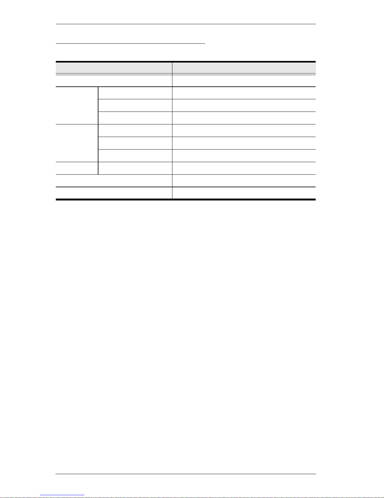
Supported operating systems are shown in the table below:
OS Version
Windows 2000 and higher
Linux RedHat 6.0 and higher
SuSE 8.2 and higher
Mandriva (Mandrake) 9.0 and higher
UNIX AIX 4.3 and higher
FreeBSD 3.51 and higher
Sun Solaris 8 and higher
Novell Netware 5.0 and higher
Mac OS 9 and higher
DOS 6.2 and higher
Chapter 1. Introduction
5
Components
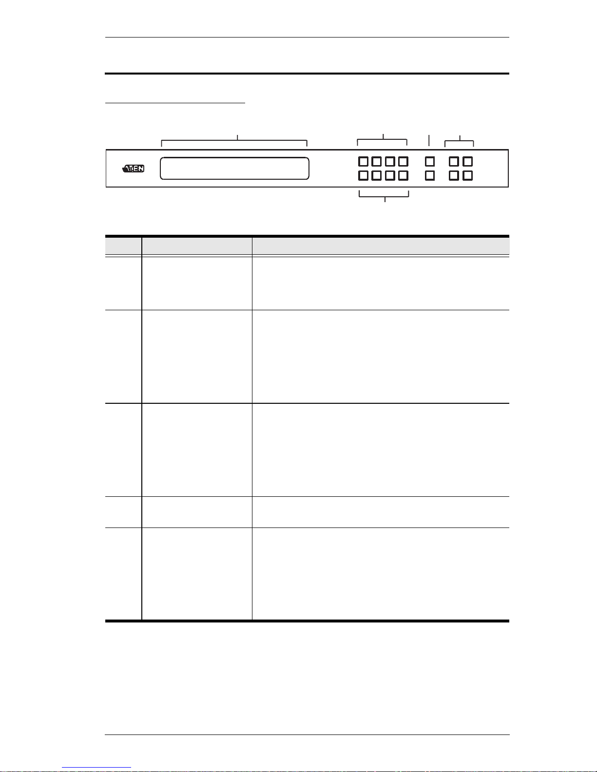
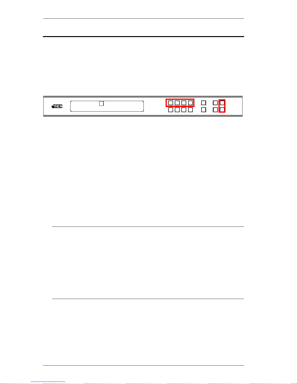
VM6404H Front View
No. Component Description
1 LCD Display The LCD Display gives a quick view of all port
connections, and shows the various options for
configuring and operating the VM6404H. For full
details, see Main Screen, page 15.
2 Input Pushbuttons These pushbuttons refer to the HDMI Input ports found
on the VM6404H rear panel. Press to select the Input
port. These pushbuttons may also correspond to menu
options, connection profiles (P1–P4) and so on.
Note: The INPUT (1–4) front panel pushbuttons have
built-in LEDs that light to indicate they have been
selected.
3 Output Pushbuttons These pushbuttons refer to the HDMI Output ports
found on the VM6404H rear panel. Press to select the
Output port. These pushbuttons may also correspond
to connection profiles (P5–P8).
Note: The OUTPUT (1–4) front panel pushbuttons
have built-in LEDs that light to indicate they have been
selected.
4Prev / Next
Pushbuttons
These pushbuttons allow you to cycle through the
menu options on the LCD display.
5 Function Pushbuttons The function pushbuttons (MENU, PROFILE, ENTER
and CANCEL) are for navigating the LCD built-in
configuration utility. For full details, see Front Panel
Pushbuttons, page 13.
Note: The MENU and PROFILE front panel
pushbuttons have built-in LEDs that light to indicate
they have been selected.
1
2
3
4
5
VM6404H User Manual
6
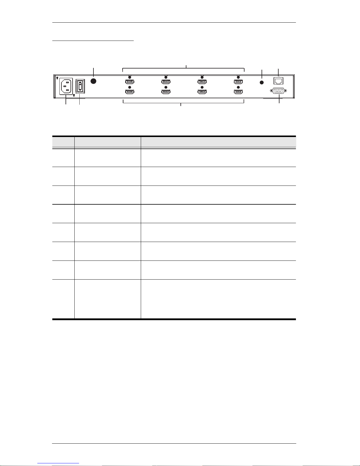
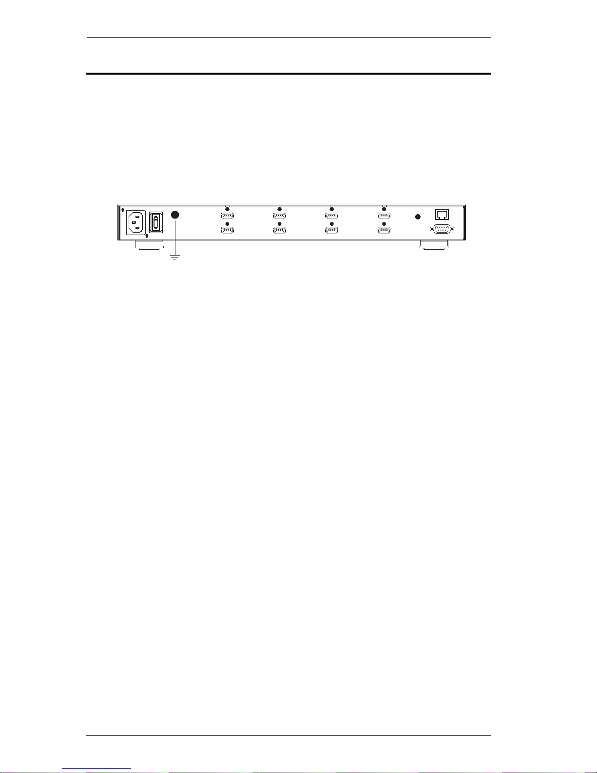
VM6404H Rear View
No. Component Description
1 Power Socket This is a standard 3-pin AC power socket. The power
cord from an AC source plugs in here.
2 Power Switch This is a standard rocker switch that powers the unit
on and off.
3 Grounding Terminal The grounding wire attaches here. See Grounding,
page 10, for further details.
4 HDMI Input Ports The cables from your HDMI source devices plug into
these ports.
5 HDMI Output Ports The cables from your HDMI display devices plug into
these ports.
6 IR Port Connect the IR Receiver unit included with your
product via this 3.5 mm Mini Stereo Jack.
7 RS-232 Serial Port Connect a computer or high-end system controller via
this serial port.
8 Ethernet Port In order to access the VM6404H’s Browser Graphical
User Interface (GUI), the VM6404H must be
connected to your network. The cable that connects
the VM6404H to your LAN plugs in here. See Cable
Connection, page 11, for further details
1
2
3
8
4
5
6
7
Chapter 1. Introduction
7
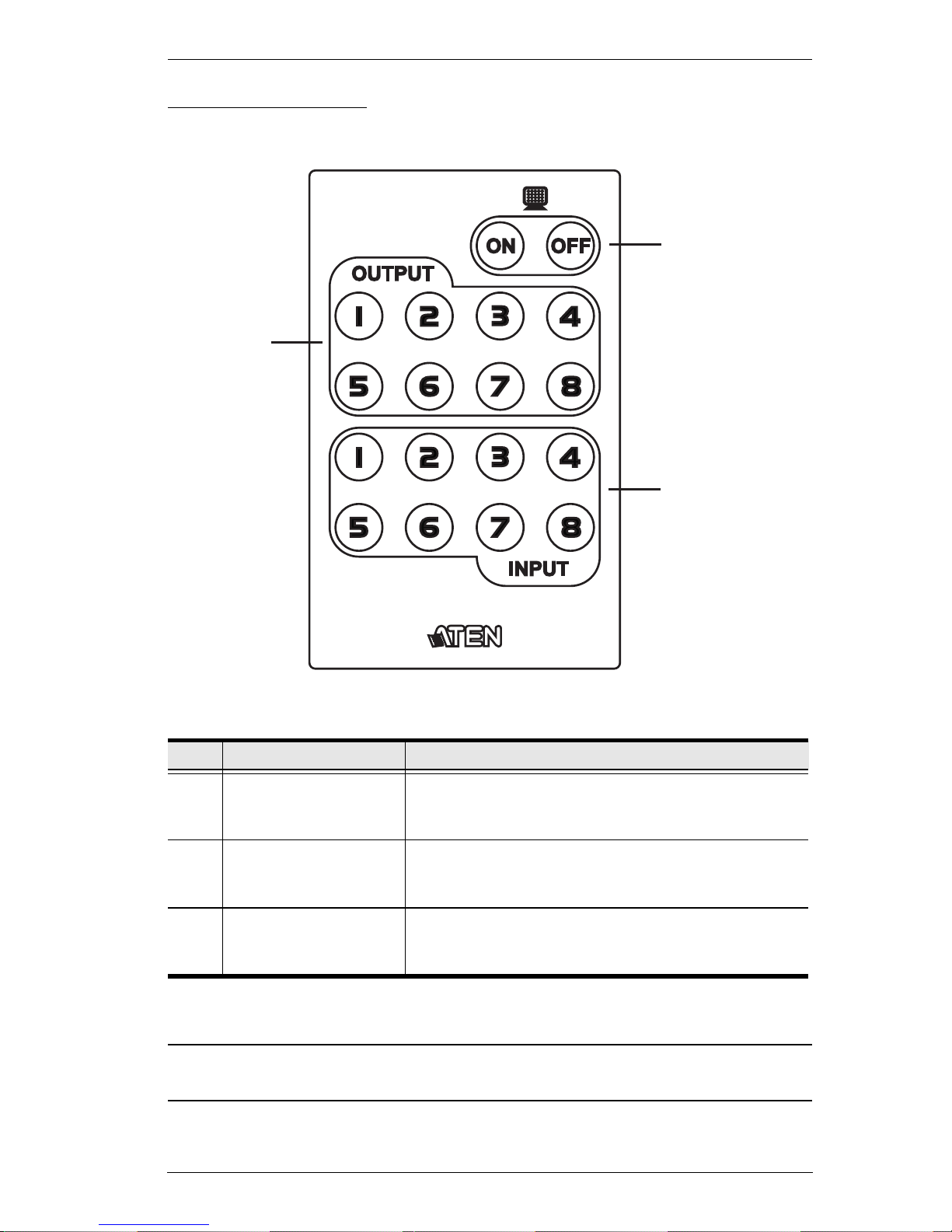
IR Remote Control
Note: The VM6404H’s IR remote control only supports use the 1~4 Input and
1~4 Output pushbuttons.
No. Component Description
1 Power ON/OFF Use the ON and OFF pushbuttons to turn the Output
displays on or off – by individual port, or all ports. (see
IR Remote Control Operation, page 31)
2 Output Pushbuttons
1–8
Press Output display pushbuttons 1–8 to select the
Output display you want to configure (see IR Remote
Control Operation, page 31).
3 Input Pushbuttons
1–8
Press Input source pushbuttons 1–8 to select the
Input source you want to display on a selected output
(see IR Remote Control Operation, page 31).
1
2
3

VM6404H User Manual
8
This Page Intentionally Left Blank
9
Chapter 2
Hardware Setup
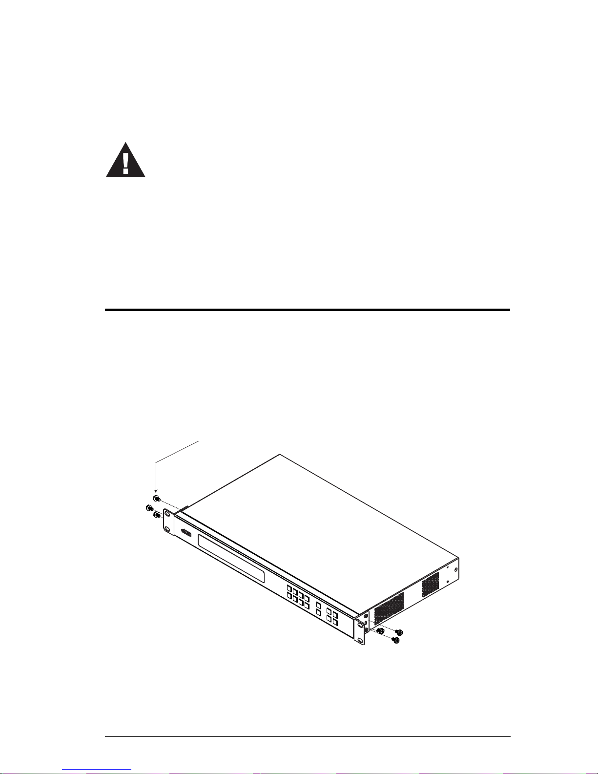
Rack Mounting
The VM6404H can be mounted in a 19” (1U) system rack. For the most
convenient front panel pushbutton configuration and operation at the local site,
mount the unit at the front of the rack, as follows:
1. Use the M3 x 6 Phillips head hex screws supplied with the Mounting Kit
to screw the rack mounting brackets onto the front of the unit.
2. Position the unit in the front of the rack and align the holes in the mounting
brackets with the holes in the rack.
3. Screw the mounting brackets to the rack.
1. Important safety information regarding the placement of this
device is provided on page 89. Please review it before
proceeding.
2. Make sure that the power to all devices connected to the
installation are turned off. You must unplug the power cords of
any computers that have the Keyboard Power On function.
Phillips Head Hex
M3 x 6
VM6404H User Manual
10
Grounding
To prevent damage to your installation, it is important that all devices are
properly grounded.
1. Use a grounding wire to ground the VM6404H by connecting one end of
the wire to the grounding terminal, and the other end of the wire to a
suitable grounded object.
2. Make sure that all devices in your VM6404H installation are properly
grounded.

Chapter 2. Hardware Setup
11
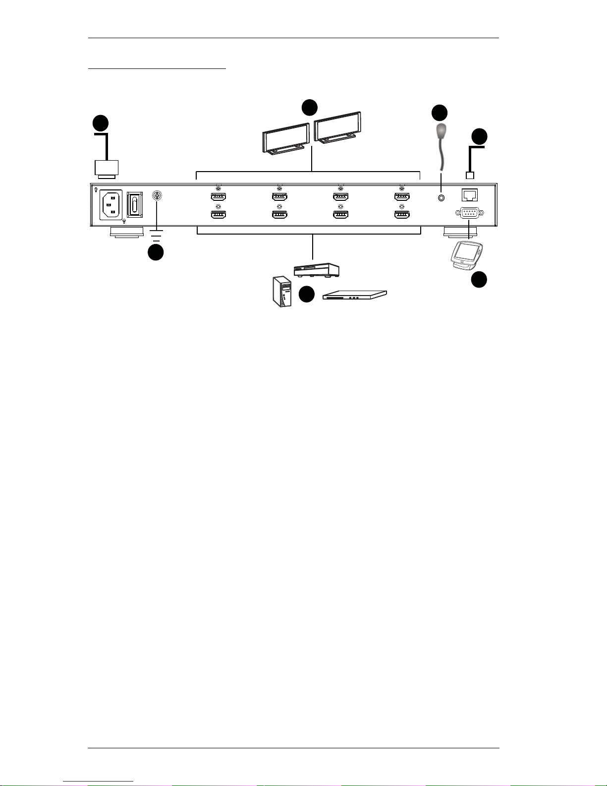
Cable Connection
Installation of the VM6404H is simply a matter of connecting the appropriate
cables. Refer to the installation diagram on the following page (the numbers in
the diagram correspond to the steps below), and do the following:
1. Use a grounding wire to ground the unit by connecting one end of the wire
to the grounding terminal, and the other end of the wire to a suitable
grounded object.
Note: Do not omit this step. Proper grounding helps to prevent damage to
the unit from surges or static electricity.
2. Connect up to 4 HDMI video sources to the HDMI Input ports
3. Connect up to 4 HDMI display devices to the HDMI Output ports
4. Connect the IR Receiver into the IR port.
5. (Optional) If using the Browser Operation features (see Browser
Operation, page 33), plug a Cat 5e cable from the LAN into the
VM6404H’s Ethernet port.
6. (Optional) If you are using the serial control function, use an appropriate
RS-232 serial cable to connect the computer or serial controller to the
VM6404H’s female RS-232 Serial port.
7. Plug the power cord supplied with the package into the VM6404H’s 3-
prong AC socket, and then into an AC power source.
8. Power on the VM6404H and all devices in the installation.
VM6404H User Manual
12
Installation Diagram
5
6
3
2
4
7
1

13
Chapter 3
Front Panel Configuration
Overview
The VM6404H can be configured and operated locally via the front panel
LCD/pushbuttons and IR Remote Control; remotely over a standard TCP/IP
connection via graphical user interface (GUI) using a web browser; via a
remote terminal session using Telnet; or by a RS-232 serial controller.
The local front panel operation is discussed in this chapter. Web GUI
Operation is discussed in Chapter 4, and RS-232 serial control is discussed in
Chapter 5.
Front Panel Pushbuttons
The front panel features an LCD display and pushbuttons for convenient
operation locally. This allows users to perform operations such as selecting
which source shows on which display, viewing the IP settings, configuring the
serial port, setting the EDID Mode / CEC / OSD /Output Status, selecting
security settings, and loading/saving profiles.
Note the following front panel pushbutton functions:
Use the MENU pushbutton to access the Menu page options: IP Setting,
Serial Port Setting, Operation Mode, Security Mode, and Save to a Profile
(see LCD Menu Organization, page 19).
Use the PROFILE pushbutton to switch between the connection profiles
which have been added to the Profile List (see Profile List, page 35).
Pressing this pushbutton for longer than 3 seconds displays the Save to a
Profile page (see Save to a Profile, page 28).
Use the CANCEL pushbutton to go back to a previous page, return to the
Main Screen, stop or exit an operation.
Use the ENTER pushbutton to select options and confirm operations.
Use the INPUT / OUTPUT (1-4) pushbuttons to select the Input/Output
port. These pushbuttons may also correspond to menu options, connection
profiles, and so on.
The VM6404H provides Prev / Next pushbuttons to navigate the menus.
VM6404H User Manual
14
Enter Password
Upon VM6404H startup, check the front panel LCD to view the loading
progress. If the Password screen / LCD Menu fails to load, an error message
displays. Reset the unit and try again.
If you are accessing the VM6404H for the first time, the Password screen
appears as soon as the LCD loading process is done. Enter the default password
1234 to continue to the Main Screen (see Main Screen, page 15).
Additionally, the Password Screen appears if the VM6404H has been
configured to require a password for Front Panel operation (see Security Mode,
page 26).
To enter a password, do the following:
1. In the Enter Password field, check that the cursor is at the first asterisk
(*) and flashing.
2. Use the front panel Input Port pushbuttons (1–4) to enter the 4-digit
password. After the fourth digit has been entered correctly, the Main
Screen displays.
3. Press Cancel to clear the password. The digits revert to 4 asterisks and the
cursor goes back to the first asterisk.
Note: 1. The VM6404H password can be any four digit combination
between 1111 to 4444. The default password is 1234.
2. If you enter an incorrect password, the cursor goes back to the
first digit and reverts to flashing. The Incorrect Password message
displays at the bottom of the screen, but clears as soon as a new
password is entered.
3. If Password option is Enabled (see Security Mode, page 26), the
LCD display time-out is 5 minutes by default.
Enter Password: * * * *
Incorrect Password

Chapter 3. Front Panel Configuration
15
Main Screen
The Main Screen shows the Input ports in the top row, which are tied to the
Output ports shown in sequential order (1–4) at the bottom row.
The front panel pushbutton label (1–4) corresponds to the Input ports and
Output ports on the unit’s rear panel.
Use the Menu pushbutton to view the LCD Menu (see LCD Menu
Organization, page 19).
Use the Profile pushbutton to switch between profile connections (see
Profile List, page 35).
Port Switching
From the Main Screen, users can configure the Input-to-Output port
connections to associate an Input source device to an Output display.
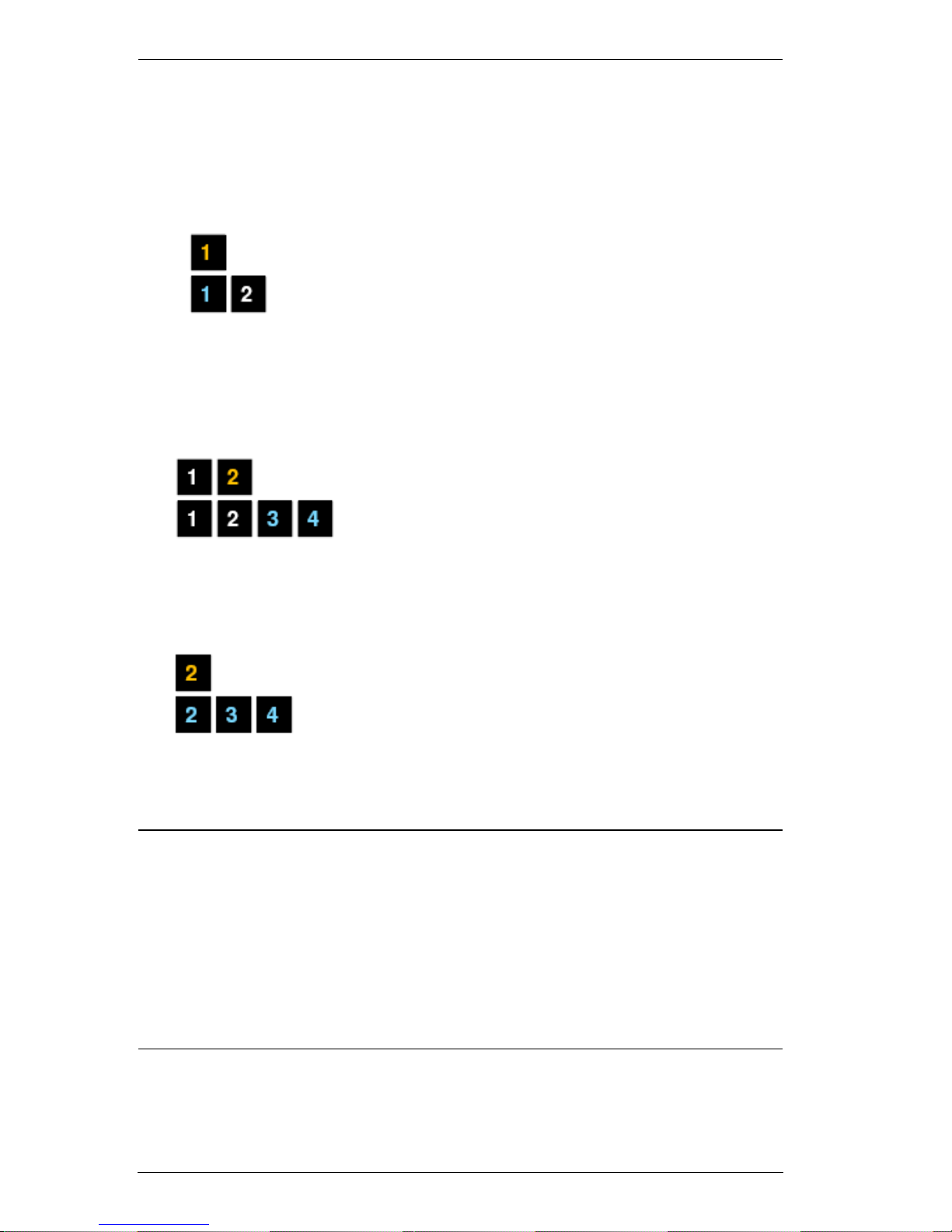
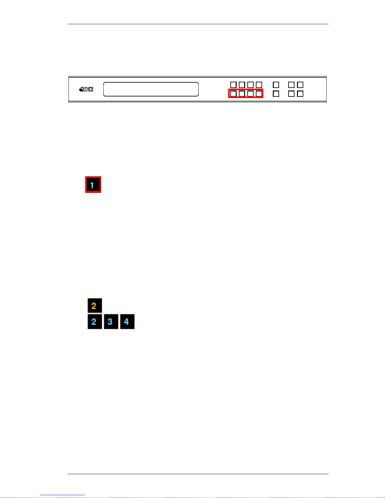
Input Port Selection
Use the Input Port pushbuttons to select the Input port you want to configure.
To select which input source displays on each output port, do the following:
1. Press any Input port pushbutton (1–4). The Output port LED(s) tied to the
said Input port light(s) up (steady).
In the example below, pressing Input port 1 shows it is tied to Output ports
1 and 2.
(Continues on next page.)
INPUT 1 2 3 4
OUTPUT 1 2 3 4
P1
INPUT 1 2 3 4
OUTPUT 1 2 3 4
VM6404H User Manual
16
(Continued from previous page.)
2. To disconnect an Output port from an Input port, press the corresponding
Output port pushbutton.
In the example below, Output port 2 has been disconnected from Input port
1.
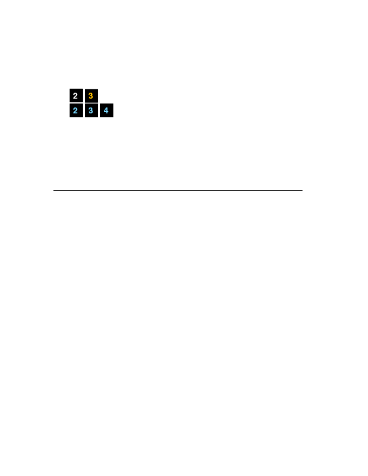
3. To switch to another Input port, press any Input port pushbutton. The
Output port LED(s) tied to the said Input port light(s) up (steady).
In the example below, pressing Input port 2 shows it is tied to Output ports
3 and 4.
4. To connect Output port 2 to Input port 2, press the Output port 2
pushbutton. The Output port 2 LED flashes (0.5 sec on, 0.2 sec off). As a
result, Input port 2 is now connected to Output ports 2, 3 and 4.
Once the signal from the selected Input port is successfully tied to the Output
port, the LEDs turn off and the LCD information is updated.
Note: 1. Pressing an Input port a second time deselects it.
2. Input ports that are not configured or tied to any output port shows
NA in the LCD screen.
3. Pressing the Cancel pushbutton once stops the Input Port Selection
operation, and the LCD displays the active setting. Pressing the
Cancel pushbutton again turns all LEDs off.
4. After 10 seconds of inactivity, all the LEDs turn off.
Chapter 3. Front Panel Configuration
17
Output Port Selection
Use the Output Port pushbuttons to select the Output port you want to
configure.
To select which output display corresponds to each input source device, do the
following:
1. Press any Output port pushbutton (1–4).
In the example below, Output port 1 pushbutton has been pressed. It is not
tied to any Input port.
2. If an Output port pushbutton is pressed a second time, it is deselected and
the LED turns off.
3. To connect the selected Output port(s) to an Input port, press the Input port
pushbutton. to which you want the Output port(s) tied. The newly selected
Input port LED flashes (0.5 sec on, 0.2 sec off), and the LCD information
is updated.
In the example below, pressing Input port 2 ties it to Output ports 2, 3 and
4.
INPUT 1 2 3 4
OUTPUT 1 2 3 4
VM6404H User Manual
18
4. To switch Output ports 2, 3 and 4 to another Input port (and disconnect it
from Input port 2), press another Input port pushbutton to which you want
it tied.
In the example below, Input port 3 has been pressed and is now connected
to Output ports 2, 3 and 4.
Note: 1. Pressing an Output port a second time deselects it.
2. Pressing the Cancel pushbutton once stops the Output Port Selection
operation, and the LCD displays the active setting. Pressing the
Cancel pushbutton again turns all LEDs off.
3. After 10 seconds of inactivity, all the LEDs turn off.
 Loading...