

Page 1
32 x 32 Modular Matrix Switch
VM3200 User Manual
www.aten.com
Page 2

Modular Matrix Solution User Manual
EMC Information
FEDERAL COMMUNICATIONS COMMISSION INTERFERENCE
STATEMENT
This equipment has been tested and found to comply with the limits for a Class
A digital device, pursuant to Part 15 of the FCC Rules. These limits are
designed to provide reasonable protection against harmful interference when
the equipment is operated in a commercial environment. This equipment
generates, uses, and can radiate radio frequency energy and, if not installed and
used in accordance with the instruction manual, may cause harmful
interference to radio communications. Operation of this equipment in a
residential area is likely to cause harmful interference in which case the user
will be required to correct the interference at his own expense.
The device complies with Part 15 of the FCC Rules. Operation is subject to the
following two conditions: (1) this device may not cause harmful interference,
and (2) this device must accept any interference received, including
interference that may cause undesired operation.
FCC Caution: Any changes or modifications not expressly approved by the
party responsible for compliance could void the user's authority to operate this
equipment.
Warning: Operation of this equipment in a residential environment could
cause radio interference.
KC Information: 이 기기는 업무용(A급)전자파 적합기기로서 판매자 또
는 사용자는 이점을 주의하시기 바라며 , 가정외의 지역에서 사용하
는 것을 목적으로합니다 .
RoHS
This product is RoHS compliant.
ii
Page 3

Modular Matrix Solution User Manual
Table of Contents
EMC Information . . . . . . . . . . . . . . . . . . . . . . . . . . . . . . . . . . . . . . . . . . . . . ii
RoHS. . . . . . . . . . . . . . . . . . . . . . . . . . . . . . . . . . . . . . . . . . . . . . . . . . . . . . ii
Table of Contents . . . . . . . . . . . . . . . . . . . . . . . . . . . . . . . . . . . . . . . . . . . .iii
About this Manual . . . . . . . . . . . . . . . . . . . . . . . . . . . . . . . . . . . . . . . . . .viii
Conventions . . . . . . . . . . . . . . . . . . . . . . . . . . . . . . . . . . . . . . . . . . . . . . . ix
Product Information. . . . . . . . . . . . . . . . . . . . . . . . . . . . . . . . . . . . . . . . . . ix
User Information . . . . . . . . . . . . . . . . . . . . . . . . . . . . . . . . . . . . . . . . . . . . . x
Online Registration . . . . . . . . . . . . . . . . . . . . . . . . . . . . . . . . . . . . . . . . x
Telephone Support . . . . . . . . . . . . . . . . . . . . . . . . . . . . . . . . . . . . . . . . x
User Notice . . . . . . . . . . . . . . . . . . . . . . . . . . . . . . . . . . . . . . . . . . . . . . x
Package Contents . . . . . . . . . . . . . . . . . . . . . . . . . . . . . . . . . . . . . . . . . . xi
VM3200 . . . . . . . . . . . . . . . . . . . . . . . . . . . . . . . . . . . . . . . . . . . . . . . xi
VM7514 / VM8514. . . . . . . . . . . . . . . . . . . . . . . . . . . . . . . . . . . . . . . . xi
VM7904 . . . . . . . . . . . . . . . . . . . . . . . . . . . . . . . . . . . . . . . . . . . . . . . . xi
VM7814 / VM8814 . . . . . . . . . . . . . . . . . . . . . . . . . . . . . . . . . . . . . . . xii
VM7804 / VM8804. . . . . . . . . . . . . . . . . . . . . . . . . . . . . . . . . . . . . . . . xii
VM7604 / VM8604. . . . . . . . . . . . . . . . . . . . . . . . . . . . . . . . . . . . . . . . xii
VM7104 . . . . . . . . . . . . . . . . . . . . . . . . . . . . . . . . . . . . . . . . . . . . . . . . xii
VM7404 . . . . . . . . . . . . . . . . . . . . . . . . . . . . . . . . . . . . . . . . . . . . . . .xiii
VE805R . . . . . . . . . . . . . . . . . . . . . . . . . . . . . . . . . . . . . . . . . . . . . . . .xiii
VE816R . . . . . . . . . . . . . . . . . . . . . . . . . . . . . . . . . . . . . . . . . . . . . . . .xiii
1. Introduction
Overview . . . . . . . . . . . . . . . . . . . . . . . . . . . . . . . . . . . . . . . . . . . . . . . . . . .1
Features . . . . . . . . . . . . . . . . . . . . . . . . . . . . . . . . . . . . . . . . . . . . . . . . . . . 4
VM3200 . . . . . . . . . . . . . . . . . . . . . . . . . . . . . . . . . . . . . . . . . . . . . . . .4
VM7514 / VM8514. . . . . . . . . . . . . . . . . . . . . . . . . . . . . . . . . . . . . . . . .5
VM7904 . . . . . . . . . . . . . . . . . . . . . . . . . . . . . . . . . . . . . . . . . . . . . . . . .6
VM7814 / VM8814. . . . . . . . . . . . . . . . . . . . . . . . . . . . . . . . . . . . . . . . .6
VM7804 / VM8804. . . . . . . . . . . . . . . . . . . . . . . . . . . . . . . . . . . . . . . . .7
VM7604 / VM8604. . . . . . . . . . . . . . . . . . . . . . . . . . . . . . . . . . . . . . . . .8
VM7104 . . . . . . . . . . . . . . . . . . . . . . . . . . . . . . . . . . . . . . . . . . . . . . . . .9
VM7404 . . . . . . . . . . . . . . . . . . . . . . . . . . . . . . . . . . . . . . . . . . . . . . . . .9
VE805R . . . . . . . . . . . . . . . . . . . . . . . . . . . . . . . . . . . . . . . . . . . . . . . . .9
VE816R . . . . . . . . . . . . . . . . . . . . . . . . . . . . . . . . . . . . . . . . . . . . . . . .10
Requirements . . . . . . . . . . . . . . . . . . . . . . . . . . . . . . . . . . . . . . . . . . . . . .12
Input / Output Board . . . . . . . . . . . . . . . . . . . . . . . . . . . . . . . . . . . . . . 12
Source Devices . . . . . . . . . . . . . . . . . . . . . . . . . . . . . . . . . . . . . . . . . .12
Display Devices. . . . . . . . . . . . . . . . . . . . . . . . . . . . . . . . . . . . . . . . . .12
Cables . . . . . . . . . . . . . . . . . . . . . . . . . . . . . . . . . . . . . . . . . . . . . . . . .13
Browsers . . . . . . . . . . . . . . . . . . . . . . . . . . . . . . . . . . . . . . . . . . . . . . .14
Optional Equipment. . . . . . . . . . . . . . . . . . . . . . . . . . . . . . . . . . . . . . .14
Components . . . . . . . . . . . . . . . . . . . . . . . . . . . . . . . . . . . . . . . . . . . . . . .15
iii
Page 4

Modular Matrix Solution User Manual
VM3200 Front View . . . . . . . . . . . . . . . . . . . . . . . . . . . . . . . . . . . . . . 15
VM3200 Rear View . . . . . . . . . . . . . . . . . . . . . . . . . . . . . . . . . . . . . . 17
VM7514 Front View . . . . . . . . . . . . . . . . . . . . . . . . . . . . . . . . . . . . . . 19
VM8514 Front View . . . . . . . . . . . . . . . . . . . . . . . . . . . . . . . . . . . . . . 19
VM7904 Front View . . . . . . . . . . . . . . . . . . . . . . . . . . . . . . . . . . . . . . 20
VM7814/VM7804 Front View . . . . . . . . . . . . . . . . . . . . . . . . . . . . . . . 20
VM8814/VM8804 Front View . . . . . . . . . . . . . . . . . . . . . . . . . . . . . . . 21
VM7604 Front View. . . . . . . . . . . . . . . . . . . . . . . . . . . . . . . . . . . . . . . 21
VM8604 Front View . . . . . . . . . . . . . . . . . . . . . . . . . . . . . . . . . . . . . . 22
VM7104 Front View . . . . . . . . . . . . . . . . . . . . . . . . . . . . . . . . . . . . . . 22
VM7404 Front View. . . . . . . . . . . . . . . . . . . . . . . . . . . . . . . . . . . . . . . 23
VE805R / VE816R Front View . . . . . . . . . . . . . . . . . . . . . . . . . . . . . . 24
VE805R / VE816R Rear View . . . . . . . . . . . . . . . . . . . . . . . . . . . . . . 24
2. Hardware Setup
Transporting and Storing the Unit. . . . . . . . . . . . . . . . . . . . . . . . . . . . . . . 25
Rack Mounting . . . . . . . . . . . . . . . . . . . . . . . . . . . . . . . . . . . . . . . . . . . . . 26
Grounding . . . . . . . . . . . . . . . . . . . . . . . . . . . . . . . . . . . . . . . . . . . . . . . . 29
Input / Output Board Installation . . . . . . . . . . . . . . . . . . . . . . . . . . . . . . . 30
Cable Connection . . . . . . . . . . . . . . . . . . . . . . . . . . . . . . . . . . . . . . . . . . 32
Installation Diagram . . . . . . . . . . . . . . . . . . . . . . . . . . . . . . . . . . . . . . 33
3. Front Panel Operation
Overview. . . . . . . . . . . . . . . . . . . . . . . . . . . . . . . . . . . . . . . . . . . . . . . . . . 35
Front Panel Pushbuttons . . . . . . . . . . . . . . . . . . . . . . . . . . . . . . . . . . . . . 35
Basic Navigation . . . . . . . . . . . . . . . . . . . . . . . . . . . . . . . . . . . . . . . . . 35
Front Panel LCD . . . . . . . . . . . . . . . . . . . . . . . . . . . . . . . . . . . . . . . . . . . 36
LCD Password . . . . . . . . . . . . . . . . . . . . . . . . . . . . . . . . . . . . . . . . . . 36
Port Switching . . . . . . . . . . . . . . . . . . . . . . . . . . . . . . . . . . . . . . . . . . . . . 38
Video / Audio Pushbutton . . . . . . . . . . . . . . . . . . . . . . . . . . . . . . . . . . 38
Profile Pushbutton . . . . . . . . . . . . . . . . . . . . . . . . . . . . . . . . . . . . . . . 43
LCD Menu . . . . . . . . . . . . . . . . . . . . . . . . . . . . . . . . . . . . . . . . . . . . . . . . 44
LCD Main Screen . . . . . . . . . . . . . . . . . . . . . . . . . . . . . . . . . . . . . . . . 45
IP Setting . . . . . . . . . . . . . . . . . . . . . . . . . . . . . . . . . . . . . . . . . . . . . . . . . 46
Serial Port Setting . . . . . . . . . . . . . . . . . . . . . . . . . . . . . . . . . . . . . . . . . . 47
Baud Rate . . . . . . . . . . . . . . . . . . . . . . . . . . . . . . . . . . . . . . . . . . . 47
Operation Mode . . . . . . . . . . . . . . . . . . . . . . . . . . . . . . . . . . . . . . . . . . . . 48
EDID . . . . . . . . . . . . . . . . . . . . . . . . . . . . . . . . . . . . . . . . . . . . . . . 48
CEC. . . . . . . . . . . . . . . . . . . . . . . . . . . . . . . . . . . . . . . . . . . . . . . . 49
OSD. . . . . . . . . . . . . . . . . . . . . . . . . . . . . . . . . . . . . . . . . . . . . . . . 50
Output Status . . . . . . . . . . . . . . . . . . . . . . . . . . . . . . . . . . . . . . . . 51
Security Mode . . . . . . . . . . . . . . . . . . . . . . . . . . . . . . . . . . . . . . . . . . . . . 53
Mode . . . . . . . . . . . . . . . . . . . . . . . . . . . . . . . . . . . . . . . . . . . . . . . 53
Change Password . . . . . . . . . . . . . . . . . . . . . . . . . . . . . . . . . . . . . 54
Saving Configurations to Profile . . . . . . . . . . . . . . . . . . . . . . . . . . . . . . . 56
Playing/Stopping the Profile Schedule . . . . . . . . . . . . . . . . . . . . . . . . . . . 57
iv
Page 5

Modular Matrix Solution User Manual
Turning Video Wall Off . . . . . . . . . . . . . . . . . . . . . . . . . . . . . . . . . . . . . . . 57
4. Browser Operation
Overview . . . . . . . . . . . . . . . . . . . . . . . . . . . . . . . . . . . . . . . . . . . . . . . . . .59
Logging In . . . . . . . . . . . . . . . . . . . . . . . . . . . . . . . . . . . . . . . . . . . . . . . . .59
Main Page . . . . . . . . . . . . . . . . . . . . . . . . . . . . . . . . . . . . . . . . . . . . . . . . 60
Menu Bar . . . . . . . . . . . . . . . . . . . . . . . . . . . . . . . . . . . . . . . . . . . . . . . . . 61
Setting the Standby Mode . . . . . . . . . . . . . . . . . . . . . . . . . . . . . . . . . . 61
Profile List . . . . . . . . . . . . . . . . . . . . . . . . . . . . . . . . . . . . . . . . . . . . . . . .62
Creating a Profile . . . . . . . . . . . . . . . . . . . . . . . . . . . . . . . . . . . . . . . . . . .63
Editing a Profile . . . . . . . . . . . . . . . . . . . . . . . . . . . . . . . . . . . . . . . . . . . .65
Editing a Profile in Normal View . . . . . . . . . . . . . . . . . . . . . . . . . . . . .67
Profile Layout Settings . . . . . . . . . . . . . . . . . . . . . . . . . . . . . . . . .67
Display Preferences. . . . . . . . . . . . . . . . . . . . . . . . . . . . . . . . . . . .68
Video Wall Settings . . . . . . . . . . . . . . . . . . . . . . . . . . . . . . . . . . . .69
Editing a Profile in Grid View . . . . . . . . . . . . . . . . . . . . . . . . . . . . . . .76
Playing a Profile . . . . . . . . . . . . . . . . . . . . . . . . . . . . . . . . . . . . . . . . . . . . 78
Change Input . . . . . . . . . . . . . . . . . . . . . . . . . . . . . . . . . . . . . . . . .80
Live Streaming View . . . . . . . . . . . . . . . . . . . . . . . . . . . . . . . . . . . 81
Importing/Exporting a Profile . . . . . . . . . . . . . . . . . . . . . . . . . . . . . . .82
Profile Scheduling . . . . . . . . . . . . . . . . . . . . . . . . . . . . . . . . . . . . . . . . . .83
Configuring Profile Schedules . . . . . . . . . . . . . . . . . . . . . . . . . . . . . .84
Adding Profiles. . . . . . . . . . . . . . . . . . . . . . . . . . . . . . . . . . . . . . . .86
Editing Profile Scheduling . . . . . . . . . . . . . . . . . . . . . . . . . . . . . . .87
System Settings . . . . . . . . . . . . . . . . . . . . . . . . . . . . . . . . . . . . . . . . . . . . 89
Overview . . . . . . . . . . . . . . . . . . . . . . . . . . . . . . . . . . . . . . . . . . . . . . . 89
General . . . . . . . . . . . . . . . . . . . . . . . . . . . . . . . . . . . . . . . . . . . . . . . .92
Basics . . . . . . . . . . . . . . . . . . . . . . . . . . . . . . . . . . . . . . . . . . . . . . 92
System Time . . . . . . . . . . . . . . . . . . . . . . . . . . . . . . . . . . . . . . . . . 92
Fan Status . . . . . . . . . . . . . . . . . . . . . . . . . . . . . . . . . . . . . . . . . . . 92
Power Status . . . . . . . . . . . . . . . . . . . . . . . . . . . . . . . . . . . . . . . . . 93
Serial Settings . . . . . . . . . . . . . . . . . . . . . . . . . . . . . . . . . . . . . . . .93
Port Settings . . . . . . . . . . . . . . . . . . . . . . . . . . . . . . . . . . . . . . . . . . . . 94
OSD/CEC . . . . . . . . . . . . . . . . . . . . . . . . . . . . . . . . . . . . . . . . . . . 94
HDCP. . . . . . . . . . . . . . . . . . . . . . . . . . . . . . . . . . . . . . . . . . . . . . . 96
Scaler. . . . . . . . . . . . . . . . . . . . . . . . . . . . . . . . . . . . . . . . . . . . . . . 97
Port Name . . . . . . . . . . . . . . . . . . . . . . . . . . . . . . . . . . . . . . . . . . .99
EDID Settings . . . . . . . . . . . . . . . . . . . . . . . . . . . . . . . . . . . . . . . . . .101
Customized Mode . . . . . . . . . . . . . . . . . . . . . . . . . . . . . . . . . . . . 104
Customized EDID Parameters. . . . . . . . . . . . . . . . . . . . . . . . . . . 105
YCBCR 4:2:0 Video Data Block. . . . . . . . . . . . . . . . . . . . . . . . . . 112
Status . . . . . . . . . . . . . . . . . . . . . . . . . . . . . . . . . . . . . . . . . . . . . . . .114
Connections . . . . . . . . . . . . . . . . . . . . . . . . . . . . . . . . . . . . . . . .114
System Information . . . . . . . . . . . . . . . . . . . . . . . . . . . . . . . . . . . . .115
Channel . . . . . . . . . . . . . . . . . . . . . . . . . . . . . . . . . . . . . . . . . . . . . . 116
IR/RS-232 . . . . . . . . . . . . . . . . . . . . . . . . . . . . . . . . . . . . . . . . . .116
v
Page 6

Modular Matrix Solution User Manual
Maintenance . . . . . . . . . . . . . . . . . . . . . . . . . . . . . . . . . . . . . . . . . . . 118
System Setup . . . . . . . . . . . . . . . . . . . . . . . . . . . . . . . . . . . . . . . . . . 118
User Account. . . . . . . . . . . . . . . . . . . . . . . . . . . . . . . . . . . . . . . . 120
Add Account . . . . . . . . . . . . . . . . . . . . . . . . . . . . . . . . . . . . . . . . 121
Permission Level . . . . . . . . . . . . . . . . . . . . . . . . . . . . . . . . . . . . . 122
Telnet Operation . . . . . . . . . . . . . . . . . . . . . . . . . . . . . . . . . . . . . . . . . . 124
Configuration Menu. . . . . . . . . . . . . . . . . . . . . . . . . . . . . . . . . . . . . . 124
1. H – Call up the command list for help . . . . . . . . . . . . . . . . . . . 124
2. IP – Set IP address . . . . . . . . . . . . . . . . . . . . . . . . . . . . . . . . . 125
3. LO – Load connections from profile . . . . . . . . . . . . . . . . . . . . 125
4. PW – Change password . . . . . . . . . . . . . . . . . . . . . . . . . . . . . 125
5. RI – Read what input is connected to nn output . . . . . . . . . . . 125
6. RO – Read what output is connected to nn input . . . . . . . . . . 125
7. SB – Set serial port baud rate . . . . . . . . . . . . . . . . . . . . . . . . . 125
8. SS – Switch input to specified output . . . . . . . . . . . . . . . . . . . 125
9. SV – Save the current connections into a profile . . . . . . . . . . 126
10. TI – Set timeout . . . . . . . . . . . . . . . . . . . . . . . . . . . . . . . . . . . 126
11. VR – Software version information . . . . . . . . . . . . . . . . . . . . 126
5. Mobile Control
Overview. . . . . . . . . . . . . . . . . . . . . . . . . . . . . . . . . . . . . . . . . . . . . . . . . 127
The Video Matrix Control App . . . . . . . . . . . . . . . . . . . . . . . . . . . . . . . . 128
Requirements . . . . . . . . . . . . . . . . . . . . . . . . . . . . . . . . . . . . . . . . . . 128
Installation and Connections . . . . . . . . . . . . . . . . . . . . . . . . . . . . . . . 128
The Control Interface . . . . . . . . . . . . . . . . . . . . . . . . . . . . . . . . . . . . 129
6. RS-232 Commands
Serial Control Protocol Commands . . . . . . . . . . . . . . . . . . . . . . . . . . . . 131
RS232 Pin Assignment . . . . . . . . . . . . . . . . . . . . . . . . . . . . . . . . . . . 131
Configuring the Serial Port . . . . . . . . . . . . . . . . . . . . . . . . . . . . . . . . 131
RS-422 / RS-485 . . . . . . . . . . . . . . . . . . . . . . . . . . . . . . . . . . . . . . . 132
Verification . . . . . . . . . . . . . . . . . . . . . . . . . . . . . . . . . . . . . . . . . . . . 132
Switch Port Command . . . . . . . . . . . . . . . . . . . . . . . . . . . . . . . . . . . 133
Mute Command . . . . . . . . . . . . . . . . . . . . . . . . . . . . . . . . . . . . . . . . 136
Volume Command . . . . . . . . . . . . . . . . . . . . . . . . . . . . . . . . . . . . . . 138
Save/Load Profile Commands . . . . . . . . . . . . . . . . . . . . . . . . . . . . . 140
EDID Mode Command . . . . . . . . . . . . . . . . . . . . . . . . . . . . . . . . . . . 142
CEC Command . . . . . . . . . . . . . . . . . . . . . . . . . . . . . . . . . . . . . . . . 144
Read Command . . . . . . . . . . . . . . . . . . . . . . . . . . . . . . . . . . . . . . . . 145
Reset Command . . . . . . . . . . . . . . . . . . . . . . . . . . . . . . . . . . . . . . . 147
Baud Rate Command . . . . . . . . . . . . . . . . . . . . . . . . . . . . . . . . . . . . 148
OSD Command . . . . . . . . . . . . . . . . . . . . . . . . . . . . . . . . . . . . . . . . 149
Echo Command . . . . . . . . . . . . . . . . . . . . . . . . . . . . . . . . . . . . . . . . 150
Scaling Command . . . . . . . . . . . . . . . . . . . . . . . . . . . . . . . . . . . . . . 151
Fan Speed Command . . . . . . . . . . . . . . . . . . . . . . . . . . . . . . . . . . . 156
Alert Command . . . . . . . . . . . . . . . . . . . . . . . . . . . . . . . . . . . . . . . . 157
vi
Page 7

Modular Matrix Solution User Manual
FrameSync Command . . . . . . . . . . . . . . . . . . . . . . . . . . . . . . . . . . .158
Long Reach Mode Command . . . . . . . . . . . . . . . . . . . . . . . . . . . . .159
Appendix
Safety Instructions. . . . . . . . . . . . . . . . . . . . . . . . . . . . . . . . . . . . . . . . . .161
General . . . . . . . . . . . . . . . . . . . . . . . . . . . . . . . . . . . . . . . . . . . . . . .161
Rack Mounting . . . . . . . . . . . . . . . . . . . . . . . . . . . . . . . . . . . . . . . . . 163
Technical Support . . . . . . . . . . . . . . . . . . . . . . . . . . . . . . . . . . . . . . . . . 164
International . . . . . . . . . . . . . . . . . . . . . . . . . . . . . . . . . . . . . . . . . . .164
North America . . . . . . . . . . . . . . . . . . . . . . . . . . . . . . . . . . . . . . . . . 164
Specifications . . . . . . . . . . . . . . . . . . . . . . . . . . . . . . . . . . . . . . . . . . . . .165
VM3200 . . . . . . . . . . . . . . . . . . . . . . . . . . . . . . . . . . . . . . . . . . . . . . 165
VM7514 / VM8514 . . . . . . . . . . . . . . . . . . . . . . . . . . . . . . . . . . . . . . 167
VM7904 . . . . . . . . . . . . . . . . . . . . . . . . . . . . . . . . . . . . . . . . . . . . . . 168
VM7814 / VM8814 . . . . . . . . . . . . . . . . . . . . . . . . . . . . . . . . . . . . . . 169
VM7804 / VM8804 . . . . . . . . . . . . . . . . . . . . . . . . . . . . . . . . . . . . . . 170
VM7604 / VM8604 . . . . . . . . . . . . . . . . . . . . . . . . . . . . . . . . . . . . . . 171
VM7104 . . . . . . . . . . . . . . . . . . . . . . . . . . . . . . . . . . . . . . . . . . . . . . 172
VM7404 . . . . . . . . . . . . . . . . . . . . . . . . . . . . . . . . . . . . . . . . . . . . . . 173
VE805R . . . . . . . . . . . . . . . . . . . . . . . . . . . . . . . . . . . . . . . . . . . . . . 174
VE816R . . . . . . . . . . . . . . . . . . . . . . . . . . . . . . . . . . . . . . . . . . . . . . 175
VM-PWR800 . . . . . . . . . . . . . . . . . . . . . . . . . . . . . . . . . . . . . . . . . . . 176
VM-FAN556 . . . . . . . . . . . . . . . . . . . . . . . . . . . . . . . . . . . . . . . . . . .176
Limited Warranty . . . . . . . . . . . . . . . . . . . . . . . . . . . . . . . . . . . . . . . .177
vii
Page 8
Modular Matrix Solution User Manual
About this Manual
This user manual is provided to help you get the most from your VM3200
Modular Matrix Solution Series, which includes the following the following
product models:
Device Type Model Product Name
Modular Matrix Switch VM3200 32 x 32 Modular Matrix Switch
Input / Output Board VM7514 / VM8514 4-Port HDBaseT Input / Output Board
VM7904 4-Port 4K DisplayPort Input Board
VM7814 / VM8814 4-Port 4K HDMI Input / Output Board
VM7804 / VM8804 4-Port HDMI Input / Output Board
VM7604 / VM8604 4-Port DVI Input / Output Board
VM7104 4-Port VGA Input Board
VM7404 4-Port 3G-SDI Input Board
Video Receiver VE805R HDMI HDBaseT Lite Receiver with Scaler
VE816R 4K HDMI HDBaseT Receiver with Scaler
This manual covers all aspects of installation, configuration and operation of
the VM3200 Modular Matrix system. An overview of the information found in
the manual is provided below.
Chapter 1 Introduction introduces you to the Modular Matrix Solution
system and its components. Its purpose, features and benefits are presented,
and its front and back panel components are described.
Chapter 2 Hardware Setup describes how to set up the hardware for your
Modular Matrix Solution installation.
Chapter 3 Front Panel Operation explains the fundamental concepts
involved in operating the VM3200 at the local site via the front panel LCD
display using pushbuttons.
Chapter 4 Browser Operation provides a complete description of the
Modular Matrix Solution’s web Graphical User Interface (GUI), and how to
use it to remotely configure and operate the Modular Matrix Solution.
Chapter 5 Mobile Control introduces you to the Video Matrix Control app
and provides details on its installation requirements.
viii
Page 9

Modular Matrix Solution User Manual
Chapter 6 RS-232 Commands provides a complete list of the serial control
protocol commands used when utilizing the RS-232 Serial Port so that an extra
source device can be utilized in the installation.
Appendix provides specifications and other technical information regarding
the Modular Matrix Solution.
Note:
Read this manual thoroughly and follow the installation and operation
procedures carefully to prevent any damage to the device or to any other
connected devices.
The VM3200 product firmware may have been updated with new features
after the release of this manual. For an up-to-date VM3200 user manual,
visit http://www.aten.com/global/en/
Conventions
This manual uses the following conventions:
Monospaced Indicates text that you should key in.
[ ] Indicates keys you should press. For example, [Enter] means to
press the Enter key. If keys need to be chorded, they appear
together in the same bracket with a plus sign between them:
[Ctrl+Alt].
1. Numbered lists represent procedures with sequential steps.
♦ Bullet lists provide information, but do not involve sequential steps.
→ Indicates selecting the option (on a menu or dialog box, for
example), that comes next. For example, Start
open the Start menu, and then select Run.
Indicates critical information.
→ Run means to
Product Information
For information about all ATEN products and how they can help you connect
without limits, visit ATEN on the Web or contact an ATEN Authorized
Reseller. Visit ATEN on the Web for a list of locations and telephone numbers:
International http://www.aten.com
ix
Page 10

Modular Matrix Solution User Manual
User Information
Online Registration
Be sure to register your product at our online support center:
International http://eservice.aten.com
Telephone Support
For telephone support, call this number:
International 886-2-8692-6959
China 86-400-810-0-810
Japan 81-3-5615-5811
Korea 82-2-467-6789
North America 1-888-999-ATEN ext 4988
1-949-428-1111
User Notice
All information, documentation, and specifications contained in this manual
are subject to change without prior notification by the manufacturer. The
manufacturer makes no representations or warranties, either expressed or
implied, with respect to the contents hereof and specifically disclaims any
warranties as to merchantability or fitness for any particular purpose. Any of
the manufacturer's software described in this manual is sold or licensed as is.
Should the programs prove defective following their purchase, the buyer (and
not the manufacturer, its distributor, or its dealer), assumes the entire cost of all
necessary servicing, repair and any incidental or consequential damages
resulting from any defect in the software.
The manufacturer of this system is not responsible for any radio and/or TV
interference caused by unauthorized modifications to this device. It is the
responsibility of the user to correct such interference.
The manufacturer is not responsible for any damage incurred in the operation
of this system if the correct operational voltage setting was not selected prior
to operation. PLEASE VERIFY THAT THE VOLTAGE SETTING IS
CORRECT BEFORE USE.
Caution: There is a risk of explosion if the battery is replaced by an incorrect
type. Always dispose of used batteries according to the relevant instructions.
x
Page 11

Modular Matrix Solution User Manual
Package Contents
Check to make sure that all of the components are present and in good order.
If anything is missing or was damaged in shipping, contact your dealer.
VM3200
The VM3200 package consists of:
1 VM3200 Modular Matrix Switch
1Power Cord
1 Terminal Block
1 Fan Module (pluggable)
1 Power Module (pluggable)
1 User Instructions
VM7514 / VM8514
The 4-Port HDBaseT Input / Output Board package consists of:
1 VM7514 4-Port HDBaseT Input Board / 1 VM8514 4-Port HDBaseT
Output Board
4 Terminal Blocks
1 IR Transmitter
1 IR Receiver
1 User Instructions
VM7904
The 4-Port 4K DisplayPort Input Board package consists of:
1 VM7904 4-Port 4K DisplayPort Input Board
4 Terminal Blocks
1 User Instructions
xi
Page 12

Modular Matrix Solution User Manual
VM7814 / VM8814
The 4-Port 4K HDMI Input / Output Board package consists of:
1 VM7814 4-Port 4K HDMI Input Board / 1VM8814 4-Port 4K HDMI
Output Board
4 Terminal Blocks
4 HDMI LockPro
1 User Instructions
VM7804 / VM8804
The 4-Port HDMI Input / Output Board package consists of:
1 VM7804 4-Port HDMI Input Board / 1 VM8804 4-Port HDMI Output
Board
4 Terminal Blocks
1 User Instructions
VM7604 / VM8604
The 4-Port DVI Input / Output Board package consists of:
1 VM7604 4-Port DVI Input Board / 1 VM8604 4-Port DVI Output
Board
4 Terminal Blocks
1 User Instructions
VM7104
The 4-Port VGA Input Board package consists of:
1 VM7104 4-Port VGA Input Board
4 Terminal Blocks
1 User Instructions
xii
Page 13

Modular Matrix Solution User Manual
VM7404
The 4-Port 3G-SDI Input Board package consists of:
1 VM7404 4-Port 3G-SDI Input Board
4 Terminal Blocks
1 User Instructions
VE805R
The HDMI HDBaseT Lite Receiver with Scaler package consists of:
1 VE805R HDMI HDBaseT Lite Receiver with Scaler
1 Power Adapter
1 Terminal Block
1 IR Transmitter
1 IR Receiver
1 User Instructions
VE816R
The 4K HDMI HDBaseT Receiver with Scaler package consists of:
1 VE816R 4K HDMI HDBaseT Receiver with Scaler
1 IR Transmitter
1 IR Receiver
1 Terminal Block
1 Power Adapter
1 User Instructions
xiii
Page 14

Modular Matrix Solution User Manual
This Page Intentionally Left Blank
xiv
Page 15

Chapter 1
Introduction
Overview
This ATEN Modular Matrix Solution Series is comprised of the VM3200
Modular Matrix Switch, input boards, output boards, and ATEN video receiver
(VE805R / VE816R).
The VM3200 Modular Matrix Switch offers advanced access and real-time
control of multiple local and remote A/V input devices and displays from a
single chassis. Operators can work from 4 x 4 up to 32 x 32 inputs and outputs
simultaneously, as well as incorporate multiple digital video formats within the
setup. It uses TMDS technology to support high speed data transfer at 1080p /
1920 x 1200 @ 60Hz / 4K x 2K @ 30Hz (4:4:4).
The VM7514 / VM8514 4-Port HDBaseT Input/Output Boards offers an easy
way to route any of 4 HDBaseT audio/video sources to any of 4 HDBaseT
display devices, in combination with the ATEN Modular Matrix Switch. When
the VM8514 HDBaseT Output Board is used in conjunction with the VE805R
HDBaseT Receiver or VE816R 4K HDMI HDBaseT Receiver with Scaler, it
features Seamless Switch technology and video wall functionality.
The VM7904 is a 4-Port 4K DisplayPort Input Board that works with an ATEN
Modular Matrix Switch to offer an easy way that routes 4 DisplayPort video
and audio sources to up to 16 or 32 displays. In addition to the DisplayPort
interface that carries digital A/V signal, the VM7904 also provides 4 stereo
audio input ports that allow stereo audio to be routed independently or
embedded for HDMI output. Ideal for high-resolution video wall applications,
the VM7904 effectively routes DisplayPort sources with 4K resolution up to
4096x2160@30Hz (4:4:4) and EDID Expert technology for the optimum
resolutions across different displays.
The VM7814 / VM8814 is a 4-Port 4K HDMI input/output board that works
with VM3200 to route 4 HDMI sources to 4 displays. The VM7814 / VM8814
is equipped with 4 input/output ports to allow for stereo audio embedding and
audio extraction. The VM8814 supports Seamless Switch
TM
to ensure real-
1
Page 16

Modular Matrix Solution User Manual
time video switching, a built-in 4K scaler to handle videos of different
resolutions, and EDID Expert
TM
to ensure high video quality.
The VM7804 / VM8804 4-Port HDMI Input / Output Board is a hot-swappable
I/O board that offers an easy way to route any of 4 audio/video sources to any
of 4 displays and installs in the Modular Matrix Switch. The VM8804 supports
Seamless Switch technology that provides video switching in real-time, a built
in scaler that handles different video resolutions, and EDID Expert technology
for fast smooth switching between displays. The VM7804 / VM8804 also
supports separate stereo audio signals that can be routed independently and
extracted from embedded HDMI audio signals.
The VM7604 / VM8604 4-Port DVI Input / Output Board is a hot-swappable
I/O board that offers an easy way to route any of 4 audio/video sources to any
of 4 displays and installs in the Modular Matrix Switch. The VM8604 supports
Seamless Switch technology that provides video switching in real-time, a built
in scaler that handles different video resolutions and EDID Expert technology
for fast smooth switching between displays.
The VM7104 4-Port VGA Input Board offers an easy way to route 4 VGA
video and audio sources to 4 displays and speakers. In addition, the VM7104
can be mixed with any modular output boards on the VM3200 for optimum
flexibility.
The VM7404 is a 4-Port 3G-SDI input board provides the capability to connect
to SDI sources, such as 3G-SDI, HD-SDI and SD-SDI, and supports high
quality video resolutions up to 1080p @ 60Hz. The VM7404 also supports
separate analog stereo audio signals for independent routing.
The VE805R HDMI HDBaseT Lite Receiver with Scaler / VE816R 4K HDMI
HDBaseT Receiver with Scaler can be combined with an ATEN HDMI
HDBaseT transmitter or splitter to extend your HDMI display up to 100 m
from the source using a single Cat 6a cable or ATEN 2L-2910 Cat 6 cable.
With a built-in scaler, the VE805R / VE816R supports the scaling of different
video resolutions. When combined with ATEN HDBaseT output boards, it
supports video wall functionality. In addition, the VE805R / VE816R is
equipped with RS-232 and IR signaling pass-through which allows RS-232
and IR channel control from the remote to local unit, to control the HDMI
source, or from the local to remote unit, to control the display device. The
VE805R / VE816R is HDCP compliant.
2
Page 17

Chapter 1. Introduction
Combining these devices, this solution can be conveniently customized,
allowing users to independently switch and route video and/or audio signals to
various monitors, displays, projectors, and/or speakers simply by pressing
front panel pushbuttons. The VM3200’s built-in Scaler encodes video formats
in order to provide seamless, real-time switching while ensuring stable signal
transmission. In addition, the front panel LCD shows a quick view of active
port connections, and includes an option to select an EDID Mode that yields
the best resolution across different monitors.
The VM3200 is easily expandable and accommodates ATEN’s hot-swappable
I/O boards. Equipped with automatic signal conversion, it allows a
combination of digital video formats, thus making it ideal for large-scale A/V
applications.
Setup is fast and easy; install the modular I/O boards by sliding them into the
VM3200’s rear panel slots, then plug the device cables into the appropriate
ports on the I/O boards and your ready.
This solution can be connected to the network through the VM3200’s LAN
port, allowing the installation to take advantage of internal Cat 5 Ethernet
wiring built into most modern commercial buildings. Once initial network
setup has been accomplished at the local level, the VM3200 can be
conveniently managed remotely using any web browser and a free app, the
ATEN Video Matrix Control App.
Furthermore, for complete systems integration, the VM3200’s built-in RS-232
and RS-485/RS-422 ports allows the switch to be configured through a highend controller or PC.
The ATEN Modular Matrix Solution Series is a powerful integrated A/V setup
targeted towards broadcasting stations, traffic and transportation-related
control rooms, emergency service centers and any application that requires
customizable high speed A/V signal routing.
3
Page 18

Modular Matrix Solution User Manual
Features
VM3200
Connects any of 32 video sources to any of 32 displays in combination
with ATEN Modular Matrix I/O Boards
Multiple means for system configuration including front-panel
pushbuttons, RS-232/422/485 control, and Ethernet connections for web
GUI or Telnet
4K resolutions – up to UHD (3840 x 2160) and DCI (4096 x 2160) with
refresh rates of 30 Hz (4:4:4) and 60 Hz (4:2:0)*
Seamless Switch™ – features close-to-zero second switching for
continuous video streams, real-time switching, and stable signal
transmissions*
Scaler – features a video scaling function to convert input resolutions to
the optimum display resolutions*
Video wall – allows you to create custom video wall layouts via intuitive
web GUI*
Live stream of connected video channels and image preview of video wall
layouts via web GUI
Profile scheduling – plays connection profiles based on user-defined
schedules
Supports free mobile control using the Video Matrix Control App
EDID Expert™ – selects optimum EDID settings for smooth power-up,
high-quality display and use of the best resolution across different screens
Audio-enabled – HDMI audio can be extracted and stereo audio can be
embedded*
Bi-directional RS-232 channel – allows you to control connected serial
devices through the web GUI
Supports redundant power module for higher reliability
Hot-pluggable design for easy integration of I/O boards, fan module, and
power supplies
HDCP 2.2 Compatible*
HDMI: 3D, Deep Color, 4K*
Consumer Electronics Control (CEC) supported*
Rack mountable (9U design)
ESD protection for HDMI
4
Page 19

Chapter 1. Introduction
Note:
Features marked with an asterisk (*) are supported only with specific I/O
boards. For more information, see the feature descriptions for I/O boards
in this manual.
The maximal output resolution, and the Scaler, Seamless Switch™ and
video wall features are only supported with certain I/O boards. For more
details, refer to the specifications of the particular I/O boardsl.
When Seamless Switch™ or Video Wall is enabled, videos may not
display within range, in which case make sure to adjust the display settings
on your device.
Video outputs will not display 3D, Deep Color, or interlace (i.e., 1080i)
resolutions correctly if Seamless Switch™ is enabled. To use these
features, make sure to first disable Seamless Switch™.
VM7514 / VM8514
Compatible with the VM3200 / VM1600A; mix and match with modular
I/O boards of any type for optimum flexibility
Superior video quality up to 4K when used with VE816R
Long-distance transmission up to 100 m
Bi-directional RS-232 channel transmits signals over Cat 6/6a cable to
control a display or other devices
HDBaseT Connectivity – extends 4 HDBaseT connections over a long
distance via a single Cat 6/6a cable or ATEN 2L-2910 Cat 6 cable
HDBaseT Anti-jamming – resists signal interference during high-quality
video transmissions using HDBaseT technology
Seamless Switch™ – features close-to-zero second switching that provides
continuous video streams, real-time switching, and stable signal
transmissions (VM8514 only)*
Video wall – allows you to create custom video wall layouts via intuitive
web GUI (VM8514 only)*
Bi-directional IR channel – full range IR transmission (30 ~ 56 kHz) is
processed one direction at a time
Note:
The Seamless Switch™ and video wall functions are only available when
used with the VE805R and VE816R.
5
Page 20

Modular Matrix Solution User Manual
When Seamless Switch™ or Video Wall is enabled, videos may not
display within range, in which case make sure to adjust the display settings
on your device.
Video outputs will not display 3D, Deep Color, or interlace (i.e., 1080i)
resolutions correctly if Seamless Switch™ is enabled. To use these
features, make sure to first disable Seamless Switch™.
VM7904
Compatible with the VM3200 / VM1600A; mix and match with modular
I/O boards of any type for optimum flexibility
Connects up to 4 DisplayPort inputs to up to 16 (VM3200) or 32
(VM1600A) displays
Superior video quality – up to 4096 x 2160 / 3840 x 2160 @ 30 Hz (4:4:4)
Audio-enabled - stereo audio can be routed independently or embedded
for HDMI output
EDID Expert™ – selects optimum EDID settings for smooth power-up
and highest quality display
Support DP1.1 with data rate up to 10.8 Gbps (2.7 Gbps per lane)
HDCP 2.2 Compliant
Hot-swappable design for easy integration and maintenance
Note: When the VM7904 is used with the VM8514+VE805R/VE816R,
VM8804, VM8814, or VM8604, the Seamless Switch™, scaler, and
video wall functions can be activated.
VM7814 / VM8814
Compatible with the VM3200 / VM1600A; mix and match with modular
I/O boards of any type for optimum flexibility
Superior video quality – HDTV resolutions of 480p, 720p, 1080i, and
1080p (1920 x 1080); 4K2K @ 60Hz (4:2:0)
Audio-enabled, HDMI audio can be extracted and stereo audio can be
embedded
Scaler – features a 4K video scaling function to convert input resolutions
to the optimum display resolutions* (VM8814 only)
6
Page 21

Chapter 1. Introduction
Seamless Switch™ – features close-to-zero-second switching to provide
continuous video streams, real-time switching, and stable signal
transmissions* (VM8814 only)
Video Wall – allows you to create custom video wall layouts via intuitive
web GUI (VM8814 only)
HDMI (3D, Deep Color)*; HDCP 2.2 Compatible
Cable Quality Tester – examines the HDMI cable quality
Consumer Electronics Control (CEC) support
EDID Expert™ – selects optimum EDID settings for smooth power-up
and highest quality display
FrameSync – prevents image tearing by synchronizing the scaler output
frame rate to the input signal frame rate (VM8814 only)
Note:
When Seamless Switch™ or Video Wall is enabled, videos may not
display within range, in which case make sure to adjust the display settings
on your device.
When Seamless Switch™ is enabled, video outputs will not display 3D,
Deep Color, or interlace (i.e., 1080i) resolutions correctly.
VM7804 / VM8804
Compatible with the VM3200 / VM1600A; mix and match with modular
I/O boards of any type for optimum flexibility
Superior video quality – HDTV resolutions of 480p, 720p, 1080i (1920 x
1080), and 1080p (1920 x 1080)
Audio-enabled, HDMI audio can be extracted and stereo audio can be
embedded
Scaler – features a video scaling function to convert input resolutions to
the optimum display resolutions* (VM8804 only)
Seamless Switch™ – features close-to-zero-second switching to provide
continuous video streams, real-time switching, and stable signal
transmissions* (VM8804 only)
Video Wall – allows you to create custom video wall layouts via intuitive
web GUI (VM8804 only)
HDMI (3D, Deep Color); HDCP 1.4 Compatible
7
Page 22

Modular Matrix Solution User Manual
Consumer Electronics Control (CEC) support
EDID Expert™ – selects optimum EDID settings for smooth power-up
and highest quality display
Note:
When Seamless Switch™ or Video Wall is enabled, videos may not
display within range, in which case make sure to adjust the display settings
on your device.
When Seamless Switch™ is enabled, video outputs will not display 3D,
Deep Color, or interlace (i.e., 1080i) resolutions correctly. To use these
features, make sure to first disable Seamless Switch™.
VM7604 / VM8604
Compatible with the VM3200 / VM1600A; mix and match with modular
I/O boards of any type for optimum flexibility
4 DVI-D input ports (VM7604); 4 DVI-D output ports (VM8604)
Scaler – features a video scaling function to convert input resolutions to
the optimum display resolutions* (VM8604 only)
Seamless Switch™ – features close-to-zero-second switching to provide
continuous video streams, real-time switching, and stable signal
transmissions* (VM8604 only)
Video Wall – allows you to create custom video wall layouts via intuitive
web GUI (VM8604 only)
HDCP 1.4 Compatible
EDID Expert™ – selects optimum EDID settings for smooth power-up
and highest quality display
Built-in EDID wizard – provides an easy way to customized EDID
settings
Audio-enabled, HDMI audio (VM7804 / VM7814) can be extracted to
VM8604; VM7604’s stereo audio can be embedded to HDMI audio
(VM8804 / VM8814)
Note:
When Seamless Switch™ or Video Wall is enabled, videos may not
display within range, in which case make sure to adjust the display settings
on your device.
8
Page 23

Chapter 1. Introduction
When Seamless Switch™ is enabled, video outputs will not display 3D,
Deep Color, or interlace (i.e., 1080i) resolutions correctly. To use these
features, make sure to first disable Seamless Switch™.
VM7104
Compatible with the VM3200; mix and match with modular I/O boards of
any type for optimum flexibility
Connects up to 4 VGA or Component inputs
Supports RGBHV / RGBS / YPbPr / YCbCr input signals
Audio-enabled, stereo audio can be embedded into HDMI audio (VM8804
/ VM8814)
Note: When the VM7104 is used with the VM8514+VE805R/VE816R,
VM8804, VM8814, or VM8604, the Seamless Switch™, scaler, and
video wall functions can be activated.
VM7404
Connects up to 4 SDI inputs
Compatible with the VM3200; mix and match with modular I/O boards of
any type for optimum flexibility
Support SD-SDI, HD-SDI, and 3G-SDI formats
Audio-enabled, stereo audio can be embedded into HDMI audio (VM8804
/ VM8814)
Note: When the VM7404 is used with the VM8514+VE805R/VE816R,
VM8804, VM8814, or VM8604, the Seamless Switch™, scaler, and
video wall functions can be activated.
VE805R
Extends HDMI, RS-232, and IR signals up to 70 m over a single Cat 5e/6/
6a cable
HDMI (3D, Deep Color); HDCP 1.4 compliant
Superior video quality – 1080p@60m (Cat 5e/6); 70m (Cat 6a)
Scaler – scales videos of different resolutions to their optimal output for
display and to avoid black screen*
9
Page 24

Modular Matrix Solution User Manual
Video Wall – features video wall profiles that allows for custom screen
layouts via an intuitive web GUI*
Seamless Switch™ – close-to-zero second switching that provides
continuous video streams, real-time switching, and stable signal
transmissions*
HDBaseT Anti-jamming – resists signal interference during high-quality
video transmissions using HDBaseT technology
Bi-directional RS-232 channel – allows for control using serial terminals
or serial devices, such as touch screens and barcode scanners
Bi-directional IR channel – IR transmission is processed one direction at a
time*
Firmware upgradeable
Built- in 8KV / 15 KV ESD protection
Plug-and-play
Rack-mountable
Note:
The Seamless Switch™ and the video wall functions are only available
when the VE805R is used with the ATEN HDBaseT I/O boards.
When Seamless Switch™ or Video Wall is enabled, videos may not
display within range, in which case make sure to adjust the display settings
on your device.
When Seamless Switch™ is enabled, video outputs will not display 3D,
Deep Color, or interlace (i.e., 1080i) resolutions correctly. To use these
features, make sure to first disable Seamless Switch™.
The VE805R supports full-frequency IR signals from 30 kHz to 56 kHz.
VE816R
Extends HDMI, RS-232, and IR signals up to 100 m over a single
Cat 5e/6/6a or ATEN 2L-2910 Cat 6 cable
HDCP 2.2 compatible
Superior video quality (4K up to 100m; 1080p up to 150m)
HDBaseT Long Reach Mode – activated by RS-232 commands, Long
Reach Mode extends signals up to 150 m, 1080p, via a single Cat 5e/6
cable
10
Page 25

Chapter 1. Introduction
Scaler – scales videos of different resolutions to their optimal output for
display and to avoid black screen
Video Wall – features video wall profiles that allows for custom screen
layouts via an intuitive web GUI*
Seamless Switch™ – close-to-zero second switching that provides
continuous video streams, real-time switching, and stable signal
transmissions*
HDBaseT Anti-jamming – resists signal interference during high-quality
video transmissions using HDBaseT technology
Bi-directional RS-232 channel – allows for control using serial terminals
or serial devices, such as touch screens and barcode scanners
Bi-directional IR channel – IR transmission is processed one direction at a
time*
Cable Quality Tester – examines the category cable quality through signal
level detection from HDBaseT Matrix Switches to the VE816R.
FrameSync – prevents image tearing by synchronizing the scaler output
frame rate to the input signal frame rate
Remote Firmware upgrade
Built- in 8KV / 15 KV ESD protection
Plug-and-play
Rack-mountable
Note:
The Seamless Switch™ and the video wall functions are only available
when the VE816R is used with ATEN HDBaseT I/O boards.
When Seamless Switch™ or Video Wall is enabled, videos may not
display within range, in which case make sure to adjust the display settings
on your device.
When Seamless Switch™ is enabled, video outputs will not display 3D,
Deep Color, or interlace (i.e., 1080i) resolutions correctly. To use these
features, make sure to first disable Seamless Switch™.
The VE816R supports full-frequency IR signals from 30 kHz to 56 kHz.
11
Page 26

Modular Matrix Solution User Manual
Requirements
The following are required for a complete VM3200 Modular Matrix Solution
Series installation:
Input / Output Board
VM7514 (HDBaseT input board) and VM8514 (HDBaseT output board)
VM7904 (4-Port 4K DisplayPort Input Board)
VM7814 (4K HDMI input board) and VM8814 (4K HDMI output board)
Note: The VM7814 and VM8814 are only supported on the VM3200
using firmware version 1.1.107 or later.
VM7804 (HDMI input board) and VM8804 (HDMI output board)
VM7604 (DVI input board) and VM8604 (DVI output board)
VM7104 (VGA input board)
VM7404 (3G-SDI input board)
Source Devices
For VM7514 4-port HDBaseT input board + VE802T HDBaseT
Transmitter: Digital A/V source device with HDMI output connector(s)
For VM7904 4-Port 4K DisplayPort Input Board: Digital A/V source
device with DisplayPort output connector(s)
For VM7814 4-port 4K HDMI input board: Digital A/V source device
with HDMI output connector(s)
For VM7804 4-port HDMI input board: Digital A/V source device with
HDMI output connector(s)
For VM7604 4-Port DVI input board: Digital A/V source device with DVI
output connector(s)
For VM7104 4-Port VGA input board: A/V source device with VGA
output connector(s)
For VM7404 4-Port 3G-SDI Input Board: SDI sources, including 3G-SDI,
HD-SDI and SD-SDI
Display Devices
For VM8514 4-port HDBaseT output board + VE805R HDBaseT
Receiver / VE816R 4K HDMI HDBaseT Receiver: Digital Display
device(s) with HDMI input connector(s)
12
Page 27

Chapter 1. Introduction
Note: The VE816R is only supported by the VM8514 using firmware
version 2.1.206 or later.
For VM8814 4-port 4K HDMI output board: Digital Display device(s)
with HDMI input connector(s)
For VM8804 4-port HDMI output board: Digital Display device(s) with
HDMI input connector(s)
For VM8604 4-Port DVI output board: Digital Display device(s) with DVI
input connector(s)
Cables
1 SDI cable for each source device (VM7404)
1 Cat 5e cable for each transmitter (VM7514)
1 Cat 5e cable for each receiver (VM8514)
1 DisplayPort cable for each source device (VM7904)
1 HDMI cable for each source device (VM7814 / VM7804)
1 HDMI cable for each display device (VM8814 / VM8804)
1 DVI cable for each source device (VM7604)
1 DVI cable for each display device (VM8604)
1 VGA cable for each source device (VM7104)
1 HDMI cable for each display device (VE805R / VE816R)
1 audio cable for each audio source device
1 audio cable for each audio device / speaker (VM8814 / VM8804 / VM8604)
1 Ethernet cable (VM3200)
1 RS-232 serial cable
(VM3200 / VM7514 / VM8514 / VE805R / VE816R)
1 RS-485/RS-422 serial cable (VM3200)
1 IR cable for each IR transmitter device (VM7514 or VM8514)
1 IR cable for each IR receiver device (VM7514 or VM8514)
(VM7814 / VM7804 / VM7604)
Note: No cables are included in this package. We strongly recommend that
you purchase high-quality cables of appropriate length since this will
affect the quality of the audio and video display. Contact your dealer to
purchase the correct cable sets.
13
Page 28
Modular Matrix Solution User Manual
Browsers
In order to achieve the best performance, the browsers listed in the table below
are recommended to be used with the VM3200's GUI.
OS Java Version Browser Ver sio n
Windows 10 (64 bit) V1.8.0_121 (64 bit) Chrome 56.0.2924.87 (64 bit)
Edge 38.14393.0.0
Firefox 51.0.1
Opera 43.0.2442.1144
Windows 8.1 V1.8.0_121 IE 11
CentOS 7.0
(64Bit)
V1.8.0_121 x64) Firefox 51.0.1 x64
Optional Equipment
Depending on any optional equipment that you may have purchased, one of the
following may be included in your package. Contact your ATEN dealer to
purchase any of these additional accessories.
Model No. Description
2X-034G Easy Installation Rack Mount Kit - Short 41 to 72 cm
2X-035G Easy Installation Rack Mount Kit - Long 68 to 108 cm
2X-030G Video Wall TV Mounting Brackets (Left) 15.47 x 11.83 x
Video Wall TV Mounting Brackets
(Right)
2X-RC1600 Video Wall TV Stand 140.00 x 90.00 x
VM-PWR800 Video Matrix Power Module - -
VM-FAN556 Video Matrix Fan Module - -
14
Dimensions
(L x W x H)
(depth)
(depth)
43.00 cm
15.47 x 12.80 x
43.00 cm
207.00 cm
Weight
2.00 kg
2.00 kg
60.00 kg
-
-
Page 29
Components
1
2
3
4
5
6
7
8
8
9
10
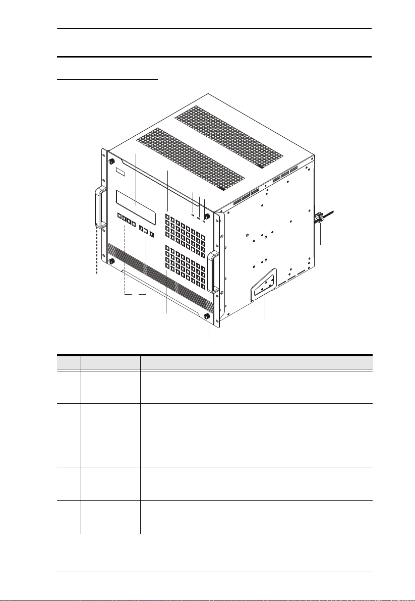
VM3200 Front View
Chapter 1. Introduction
No. Component Description
1 LCD Display The LCD Display shows the options for configuring and
operating the VM3200. See Front Panel Pushbuttons, page 35,
2 Function
Pushbuttons
for details.
Use the UP, DOWN and CANCEL buttons to navigate the LCD
display to configure the installation. Press the Video, Audio,
Menu and Profile buttons to use each function. See Front Panel
Pushbuttons, page 35, for details.
Note: The pushbuttons have LEDs that light to indicate they
have been selected.
3 Input
Pushbuttons
(1-32)
4 Output
Pushbuttons
(1-32)
These pushbuttons refer to the Input ports on the VM3200 rear
panel. Press to select the Input port. These pushbuttons may
also correspond to menu options, profiles and other selections.
These pushbuttons refer to the Output ports on the VM3200
rear panel. Press to select the Output port.
15
Page 30

Modular Matrix Solution User Manual
No. Component Description
5 Alarm LED The Alarm LED lights red to indicate the power or fan module
6 Redundant
Power LED
7 Primary Power
LED
8 Handles The two front handles are used to install the unit into a rack.
9 Recessed
Handles
10 Cable Strap A cable strap is provided to secure the power cord’s plug to the
has failed.
This LED lights green to indicate the redundant power module
is plugged in and working.
This LED lights green to indicate the primary power module is
plugged in and working.
The two side handles are used to transport the unit. Push in to
lock and unlock the handles so that they can be used to carry
the unit and be tucked away when not in use.
VM3200.
16
Page 31

VM3200 Rear View
7
1
2
3
4
5
6
8
9
Chapter 1. Introduction
No. Component Description
1 Power Switch This is a standard rocker switch that powers the unit
on and off.
2 RS-485 / RS-422
Serial Port
3 Ethernet Port In order to access the VM3200’s web Graphical User
4 RS-232 Serial Port Connect a computer or high-end system controller via
Connect a computer or high-end system controller via
this serial port.
Interface (GUI), the VM3200 must be connected to the
network. The cable that connects the VM3200 to your
LAN plugs in here. See Cable Connection, page 32,
for further details
this serial port.
5 Primary Power Supply This is a standard 3-pin power socket. The power cord
from a source plugs in here.
17
Page 32

Modular Matrix Solution User Manual
No. Component Description
6 Redundant Power
Slot (Optional)
7 Grounding Terminal The grounding wire attaches here. See Grounding,
8 Output Board slots Unscrew the cover to insert the output boards into
9 Input Board Slots Unscrew the cover to insert the Input boards into these
This slot with protective cover is used to install an
additional power supply for redundant power
protection.
Note: The extra power module is not included in the
VM3200 package.See , page 14, for details.
page 29, for further details.
these 8 vertical slots. The display devices connect to
the inserted Output boards.
8 vertical slots. The source devices connect to the
inserted Input boards.
18
Page 33

Chapter 1. Introduction
2
3
1
2
3
1
VM7514 Front View
No. Component Description
1 HDBaseT Input Ports Connect the Cat 5e cables from your HDBaseT
2 IR / RS-232
Input Ports
3 Status LED Indicates the working status of the unit.
transmitter to these ports.
Connect the cables from your IR transmitter to the mini
stereo jack ports, and connect the cables from your
RS-232 device to the RS-232 ports.
VM8514 Front View
No. Component Description
1 HDBaseT Output
Ports
2 IR / RS-232
Output Ports
3 Status LED Indicates the working status of the unit.
Connect the Cat 5e cables from your HDBaseT
receiver to these ports.
Connect the cables from your IR receiver to the mini
stereo jack ports, and connect the cables from your
RS-232 device to the RS-232 ports.
19
Page 34

Modular Matrix Solution User Manual
2
3
1
2
3
1
VM7904 Front View
No. Component Description
1 DisplayPort Input
Ports
2 Audio Input Ports Connect the cables from your audio source devices to
3 Status LED Indicates the working status of the unit.
Connect the cables from your DisplayPort video
source devices to these ports.
these ports.
VM7814/VM7804 Front View
No. Component Description
1 HDMI Input Ports Connect the cables from your HDMI video source
2 Audio Input Ports Connect the cables from your audio source devices to
3 Status LED Indicates the working status of the unit.
20
devices to these ports.
these ports.
Page 35

Chapter 1. Introduction
2
3
1
1
2
3
VM8814/VM8804 Front View
No. Component Description
1 HDMI Output Ports Connect the cables from your HDMI display devices
2 Audio Output Ports Connect the cables from your output audio devices or
3 Status LED Indicates the working status of the unit.
(monitors, projectors, TVs) to these ports.
speakers to these ports.
VM7604 Front View
No. Component Description
1 DVI Input Ports Connect the cables from your video source devices to
2 Audio Input Ports Connect the cables from your audio source devices to
3 Status LED Indicates the working status of the unit.
these ports.
these ports.
21
Page 36

Modular Matrix Solution User Manual
2
3
1
VM8604 Front View
1
2
No. Component Description
1 DVI Output Ports Connect the cables from display devices (monitors,
projectors, TVs) to these ports.
2 Audio Output Ports Connect the cables from your output audio devices or
speakers to these ports.
3 Status LED Indicates the working status of the unit.
VM7104 Front View
No. Component Description
1 VGA Input Ports Connect the cables from your VGA video source
devices to these ports.
2 Audio Input Ports Connect the cables from your audio source devices to
these ports.
3 Status LED Indicates the working status of the unit.
3
22
Page 37

Chapter 1. Introduction
1
2
3
VM7404 Front View
No. Component Description
1 SDI Input Ports Connect the cables from your video source devices to
2 Analog Stereo Audio
Input Ports
3 Status LED The VM7404 has an LED to indicate the working
these ports.
Connect the cables from your audio source devices to
these ports.
status.
23
Page 38

Modular Matrix Solution User Manual
542 3
1
76
VE805R / VE816R Front View
VE805R / VE816R Rear View
No. Component Description
1 LEDs Three LEDs – Power, Link and HDMI Out – light when
2 IRPort Connect the IR transmitter or receiver cable port into this
3 RS-232 Port Use the captive screw connectors (3 pole) to connect the
4 HDMI Output Port Connect the cable from your HDMI display device
5 Firmware Upgrade
Switch
6 HDBaseT Input Use a Cat 5e cable to connect the VE805R / VE816R to
7 Power Jack The power adapter cable plugs connects here.
the unit is properly connected to an appropriate source.
Power - lights Green to indicate the unit is receiving
power.
Link - lights Orange to indicate that communication
between VE805R / VE816R and output board is
established.
HDMI Out - lights Orange to indicate the HDMI output
signal is good. LED blinks Orange every second to
indicate that the device is in F/W upgrade mode.
mini stereo jack port.
cable from your serial device into the RS-232 port.
(monitors, projectors, TVs) into this port.
Set this switch to OFF (left) for normal operation. Set this
switch to ON (right) and reset the unit’s power to enter
firmware upgrade mode.
the VM8514 output board.
24
Page 39

Chapter 2
1. Important safety information regarding the placement of this
device is provided on page 161. Please review it before
proceeding.
2. Make sure that the power to all devices connected to the
installation are turned off. You must unplug the power cords of
any computers that have the Keyboard Power On function.
GROUNDGROUND
FAN
UP
Hardware Setup
Transporting and Storing the Unit
Its important to properly transport and store the VM3200. Follow the
instructions below to avoid damaging the VM3200 due to improper handling.
When not rack mounted, the VM3200 should be placed on a flat and level
surface with the bottom side down. The unit should never be placed with the
front, rear or sides facing the ground.
25
Page 40

Modular Matrix Solution User Manual
Rack Mounting
The Modular Matrix Swtich can be mounted in a 19” (1U) system rack. For the
most convenient front panel operation at the local site, mount the unit at the
front of the rack, as follows:
1. Position the unit in the front of the rack, and align the holes of the unit’s
built-in mounting brackets with the holes in the rack.
2. Use screws to attach the unit to the rack.
Note: 1. Please allow 1U (44 mm) of space between the top of the VM3200
and any object to prevent obstruct of the air flow.
2. To ensure the VM3200 has sufficient air flow, do not stack items on
top or in front of the unit. Proper air flow ensures safe operation and
prevents the unit from overheating.
26
Page 41

Chapter 2. Hardware Setup
PUSH (LOCK)
PUSH (LOCK)
Mounting with Brackets
You can also use mounting brackets to install the VM3200, as shown below.
Note: The Easy Installation Mounting Kit is not included with the package
(see page 14). To purchase a mounting kit please contact your dealer.
1. Screw the mounting brackets to the rack, as shown in the diagram.
2. Push in and lock the Recessed Handles, and then slide the unit along the
brackets.
27
Page 42

Modular Matrix Solution User Manual
3. Screw the front panel to the rack.
Note: 1. Please allow 1U (44 mm) of space between the top of the VM3200
and any object to prevent obstruct of the air flow.
2. To ensure the VM3200 has sufficient air flow, do not stack items on
top or in front of the unit. Proper air flow ensures safe operation and
prevents the unit from overheating.
28
Page 43

Chapter 2. Hardware Setup
Grounding
To prevent damage to your installation, it is important that all devices are
properly grounded.
1. Use a grounding wire to ground the installation using the VM3200’s rear
panel, by connecting one end of the wire to the grounding terminal, and
the other end of the wire to a suitable grounded object.
2. Make sure that all devices in your installation are properly grounded.
Note: The grounding wire is not included in the package. Please contact your
dealer for details about purchasing a grounding wire.
29
Page 44

Modular Matrix Solution User Manual
Input / Output Board Installation
To install the I/O boards in the VM3200, do the following:
Note: The eight right slots on the Modular Matrix Switch are for the Input
boards. The eight left slots on the Modular Matrix Switch are for the
Output boards.
1. On the rear of the VM3200, remove two screws from a left and right side
slot, and then remove both covers.
30
(Continues on next page.)
Page 45

Chapter 2. Hardware Setup
2. Slide an output board into a left side slot and then tighten the two screws to
secure the board to the VM3200.
3. Slide an input board into a right side slot and then tighten the screws to
secure the board to the VM3200.
4. Repeat steps 2 and 3 to install additional I/O boards.
5. Power on the VM3200.
31
Page 46

Modular Matrix Solution User Manual
Cable Connection
Refer to the installation diagram on the following page (the numbers in the
diagram correspond to the steps below), and do the following:
1. Use a grounding wire to ground the unit by connecting one end of the wire
to the grounding terminal, and the other end of the wire to a suitable
grounded object.
Note: Do not omit this step. Proper grounding helps to prevent damage to
the unit from surges or static electricity.
2. Unscrew the covers on the VM3200’s rear panel and insert the I/O boards
into the vertical slots (See Input / Output Board Installation, page 30, for
details).
3. Connect your A/V source device(s) to the Video and Audio port(s) of the
Input Board on the VM3200.
4. Connect your video display device(s) to the Video port(s) of the Output
Board on the VM3200.
5. Connect your speakers / audio output device(s) to the Audio port(s) of the
Output Board on the VM3200.
6. (Optional) If you are using the serial control function to control multiple
VM3200’s, use an appropriate serial cable to connect the computer or
serial controller to the VM3200’s female RS-485 / RS-422 captive screw
connector. The VM3200 package includes a terminal block that can be
used for this connection.
7. (Optional) To access the web interface or use the Video Matrix Control
app, plug a Cat 5e cable from the network to the VM3200’s Ethernet port.
8. (Optional) If you are using a serial control function, use an appropriate
serial cable to connect the computer or serial controller to the VM3200’s
female RS-232 serial port.
9. Plug the power cord supplied with the package into the VM3200’s 3-prong
socket, and then into a power source.
10. (Optional) Plug in an additional power module for redundancy if required.
Note: Secondary power modules are not included in the VM3200 package.
For supported power module models, see Optional Equipment,
page 14.
11. Power on the VM3200 and all devices in the installation.
32
Page 47
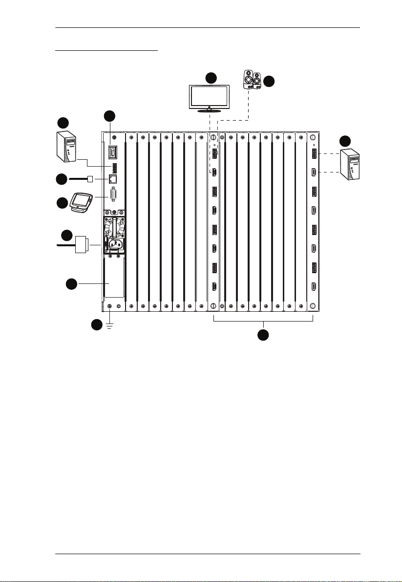
Installation Diagram
7
6
9
8
11
10
4
5
2
1
3
Chapter 2. Hardware Setup
33
Page 48

Modular Matrix Solution User Manual
This Page Intentionally Left Blank
34
Page 49

Chapter 3
Front Panel Operation
Overview
The Modular Matrix Switch installation can be configured and operated locally
via the VM3200 front panel LCD and pushbuttons.
Front Panel Pushbuttons
The VM3200 front panel has easy-to-use pushbuttons for selecting which
video/audio source shows on which display.
Basic Navigation
The VM3200’s front panel LCD display operation is easy and convenient.
Please note the following front panel button operations:
Press the VIDEO pushbutton to configure the video connections.
Press the AUDIO pushbutton to configure the audio connections.
Use the MENU pushbutton to access the Menu page options: IP Setting,
Serial Port Setting, Operation Mode, Security Mode, and Save to a Profile.
Use the PROFILE pushbutton to select a profile or switch between the
connection profiles which have been added to the Profile List (see
page 62). Pressing this pushbutton for longer than 3 seconds displays the
Save to a Profile page (see page 56).
Use the CANCEL ( ) pushbutton to go back a level, return to the Main
screen, stop or exit an operation.
Use the UP () and DOWN ( ) pushbuttons to go to the next or
previous options.
Use the Input / Output (1–32) pushbuttons to select the Input/Output port.
The pushbuttons may also correspond to menu options, profiles, and so on.
35
Page 50

Modular Matrix Solution User Manual
Enter Password: * * * *
Incorrect Password
Front Panel LCD
The VM3200 features an LCD display for convenient configuration. This
allows you to perform operations such as viewing the IP settings, configuring
the serial port, setting EDID/CEC/OSD/Output Status, selecting security
settings, and loading/saving connection profiles.
LCD Password
If the VM3200 has been configured to require a password for local operation
(see Security Mode, page 53), the password screen appears when the VM3200
is powered on, and the cursor flashes on the first digit. Enter a 4-digit password
to continue to the Main Screen.
Note: If you are accessing the VM3200 for the first time, the default password
is 1234.
To enter a password, do the following:
1. Check that the cursor is flashing on the first digit.
2. Use the front panel number pushbuttons (1-9) to enter a 4-digit password.
After the fourth digit, the cursor goes back to the first digit.
36
Page 51

Chapter 3. Front Panel Operation
3. Press Cancel to clear the password. The digits revert to 4 asterisks (*) and
the cursor returns to the first digit.
Note: 1. The VM3200 password can be any four digit combination
between 1111 to 9999.
2. If you enter an incorrect password, the cursor goes back to the
first digit and reverts to flashing. The Incorrect Password message
displays at the bottom of the screen, but clears as soon as a new
digit is entered.
3. If Password (see Security Mode, page 53) is Enabled, the LCD
display time-out is 5 minutes by default.
37
Page 52

Modular Matrix Solution User Manual
INPUT
OUTPUT
1 2 5 5* 1 1 3 4
1 2 3 4 5 6 7 8
INPUT
OUTPUT
1 2 5 5 1 1 3 4
V + A
9 10 11 12 13 14 15 16
P1
Port Switching
From the Main Screen, you can configure the Input-to-Output port connections
to associate an Input source device to an Output display.
Video / Audio Pushbutton
Before switching port connections, use the Video or Audio pushbuttons to
select whether to switch only the video or the audio signal exclusively.
Otherwise, both video and audio channels are configured together (default).
↓
:Next
Press the Video* pushbutton to configure Video connections. The built-in
LED lights up and the LCD displays Video on the lower right side. Press
the button again to cancel.
Press the Audio* pushbutton to configure Audio connections. The built-in
LED lights up and the LCD displays Audio on the lower right side. Press
the button again to cancel.
If both Video and Audio built-in LEDs are turned off, the video and audio
channels are configured together and the LCD displays V + A.
Note: Press the Video or Audio pushbutton to independently switch either
signal to a different source.
38
Page 53

Chapter 3. Front Panel Operation
INPUT
OUTPUT
1 2 5 5* 1 1 3 4
1 2 3 4 5 6 7 8
INPUT
OUTPUT
1 2 5 5 1 1 3 4
V + A
9 10 11 12 13 14 15 16
P1
Input Port Selection
Use the Input Port pushbuttons to select the Input port you want to configure.
↓
:Next
To select which input source displays on each output port, do the following:
1. Press any Input port pushbutton. The Output port LED(s) tied to the said
Input port will begin to flash. Available Output port LED(s) will light up
(steady).
In the example below, pressing Input port 1 shows it is tied to Output ports
1 and 2.
2. To disconnect an Output port from an Input port, press the corresponding
Output port pushbutton.
In the example below, Output port 2 has been disconnected from Input port
1.
(Continues on next page.)
39
Page 54

Modular Matrix Solution User Manual
3. To switch to another Input port, press any Input port pushbutton. The
Output port LED(s) tied to the said Input port will flash.
In the example below, pressing Input port 2 shows it is tied to Output ports
3 and 4.
4. To connect Output port 2 to Input port 2 in the example above, press the
Output port 2 pushbutton. The Output port 2 LED will also begin to flash
(0.5 sec on, 0.2 sec off). This indicates that Input port 2 is now connected
to Output ports 2, 3 and 4.
Once the signal from the selected Input port is successfully tied to the Output
port, the LEDs turn off and the LCD information is updated.
Note: 1. Pressing an Input port a second time deselects it.
2. Input ports that are not configured or tied to any output port do not
appear in the LCD screen.
3. Pressing the Cancel pushbutton once stops the Input Port Selection
operation and the LCD displays the active setting. Pressing the
Cancel pushbutton again turns all LEDs off.
4. After 10 seconds of inactivity, all the LEDs turn off.
40
Page 55

Chapter 3. Front Panel Operation
INPUT
OUTPUT
1 2 5 5* 1 1 3 4
1 2 3 4 5 6 7 8
INPUT
OUTPUT
1 2 5 5 1 1 3 4
V + A
9 10 11 12 13 14 15 16
P1
Output Port Selection
Use the Output Port pushbuttons to select the Output port you want to
configure.
↓
:Next
To select which output display corresponds to each input source, do the
following:
1. Press any Output port pushbutton (1-32). The selected Output port LED
lights steady.
In the example below, Output port 1 pushbutton has been pressed.
Available Input ports light up. Because no Input LEDs are flashing, no
ports have already been assigned to Output port 1.
2. If an Output port pushbutton is pressed a second time, it is deselected and
the LED turns off.
3. To connect the selected Output port(s) to an Input port, press the Input port
pushbutton to which you want the Output port(s) tied. The newly selected
Input port LED flashes (0.5 sec on, 0.2 sec off), and the LCD information
is updated.
In the example below, pressing Input port 2 ties it to Output ports 2, 3 and
4.
41
Page 56

Modular Matrix Solution User Manual
4. To switch Output ports 2, 3 and 4 to another Input port (and disconnect it
from Input port 2), press another Input port pushbutton to which you want
them tied.
In the example below, Input port 3 has been pressed and is now connected
to Output ports 2, 3 and 4.
Note: 1. Pressing an Output port a second time deselects it.
2. Pressing the Cancel pushbutton once stops the Output Port Selection
operation, and the LCD displays the active setting. Pressing the
Cancel pushbutton again turns all LEDs off.
3. After 10 seconds of inactivity, all the LEDs turn off.
42
Page 57

Chapter 3. Front Panel Operation
INPUT
OUTPUT
1 2 5 5* 1 1 3 4
1 2 3 4 5 6 7 8
INPUT
OUTPUT
1 2 5 5 1 1 3 4
9 10 11 12 13 14 15 16
V + A
P1
↓
:Next
Profile Pushbutton
From the Main screen; pressing the PROFILE pushbutton switches between
the connection profiles added to the Profile Selection list (see Profile List,
page 62). If a connection profile is in use, it is shown from the Main screen on
the lower right corner of the LCD display.
Use the front panel number pushbuttons to select a profile:
Input ports 1–32 correspond to Profile P1 to P32
Output ports 1–32 correspond to Profile P33 to P64
Note: If a Profile is available for selection, its corresponding Input/Output
port LED lights.
The selected pushbutton lights steady, and the VM3200 immediately
applies the port connections configured in the Profile. The selected Profile
is shown as P1-P64 in the LCD’s lower right corner.
Up and Down buttons correspond to the previous or next profile in the
Profile List, which can be edited via the GUI.
If there are no profiles configured, an error message “No Profile List
defined. Profile List can be edited via the Web GUI.” is displayed.
The Profile List and connections can be edited from the Profile List page
of the Browser GUI. See Profile List, page 62.
Press the Cancel pushbutton to turn off the Profile LED.
Pressing the Profile pushbutton for longer than 3 seconds displays the
Save to a Profile page (see Saving Configurations to Profile, page 56).
Note: To save a configuration to a profile using the Front Panel pushbuttons,
follow the steps in Saving Configurations to Profile, page 56.
43
Page 58

Modular Matrix Solution User Manual
LCD Menu
Use the Menu pushbutton to switch between the Main Screen and Menu page.
From the Main Screen press the Menu pushbutton to access the Menu page;
use the pushbuttons (1-32) to cycle through the menu options, starting from IP
Setting, in the order show in the table below:
Menu Page Sub-Menu Page(s)
IP Setting IP Address
Subnet Mask
Gateway
Serial Port Setting Baud Rate 9600 / 19200 / 38400 / 115200
Operation Mode EDID Default / Port1 / Remix / Customized
CEC On / NA
OSD On / NA
Output Status Video On / NA
Stereo Audio 01-32
Output
Resolution
Security Mode Mode None
Password Enable
Lock Screen
Change Password Old Password New Password
Save to a Profile Save to a Profile No. 01-32
Play/Stop the Profile Schedule
Turn Video Wall Off
01-32
Note: 1. The highlighted values are the default settings of the VM3200.
2. Upon VM3200 startup, check the front panel LCD to view the loading
progress. If the LCD Menu fails to load, an error message displays.
Reset the unit and try again.
44
Page 59

Chapter 3. Front Panel Operation
LCD Main Screen
The Main Screen shows the Input–Output port pairs, with the Output ports
shown in sequential order (1–16) at the bottom half.
INPUT
OUTPUT
INPUT
OUTPUT
1 2 5 5* 1 1 3 4
1 2 3 4 5 6 7 8
1 2 5 5 1 1 3 4
9 10 11 12 13 14 15 16
V + A
↓: Next
The front panel pushbutton label (1–32) corresponds to the Input ports
and Output ports on the unit’s rear panel.
Use the Down pushbutton to go to the next page to view ports 17–32.
Use the Menu pushbutton to go to the Menu page.
Use the Profile pushbutton to switch between profile connections (see
Profile List, page 62).
45
Page 60

Modular Matrix Solution User Manual
IP Setting
To view the VM3200’s IP settings, press the Menu pushbutton (lights). This
takes you to the Menu page, shown below:
1: IP Seng
2: Serial Port Seng
3: Operaon Mode
4: Security Mode
1. From the Menu page:
Press 1 to go to the IP Setting page.
Press 2 to go to the Serial Port Setting page.
Press 3 to go to the Operation Mode page.
Press 4 to go to the Security Mode page.
Press Down button to go to the next page.
Press Menu to return to the Menu Screen.
Press Cancel to return to the Main Screen.
2. After pressing 1, the IP address, Subnet Mask and Gateway information
are shown:
↓: Next
IP Address: 192.168.0.60
Subnet Mask: 255.255.255.0
Gateway: 192.168.0.1
*IP seng can be edited vis Web GUI
The default IP address is 192.168.0.60.
The default Subnet Mask is 255.255.255.0.
The default Gateway is 192.168.0.1.
3. Press Cancel to return to the previous step without change.
46
Page 61

Chapter 3. Front Panel Operation
1: IP Seng
2: Serial Port Seng
3: Operaon Mode
4: Security Mode
↓: Next
1: 9600
2: 19200 (In use)
3: 38400
4: 115200
Serial Port Setting
To configure the VM3200’s serial port settings, select Serial Port Setting from
the Menu page.
Baud Rate
1. Select Baud Rate Setting from the Serial Port Setting by pressing 1:
2. Press pushbuttons 1–4 to make your selection.
Baud Rate options are:
1: 9600
2: 19200
3: 38400
4: 115200
Note: The default baud rate is 19200.
3. Press Menu to return to the Menu page.
4. Press Cancel to return to the previous step without saving.
47
Page 62

Modular Matrix Solution User Manual
1: EDID Mode: Default
2: CEC
3: OSD
4: Output Status
↓: Next
1: EDID Mode: Default
2: CEC
3: OSD
4: Output Status
↓: Next
1: Port 1
2: Default (In use)
3: Remix
4: Customized
Operation Mode
The EDID, CEC, OSD, and Output Status features are adjusted from the
Operation Mode menu.
EDID (extended display identification data) is used to apply a preset video
configuration (EDID Mode), which utilizes the best resolution across
different monitors.
Consumer Electronics Control (CEC) allows interconnected HDMI
devices to communicate and respond to one remote control.
The OSD, when enabled for a port, displays real-time port switching
information on the screen.
The Output Status shows whether the video/audio of an Output port is
turned on or off.
EDID
To adjust the EDID mode, do the following:
1. From the Operation page, press pushbutton 1 to access the EDID Mode
page:
2. Press pushbuttons 1-4 to make your selection.
48
Page 63

Chapter 3. Front Panel Operation
EDID Mode options are:
EDID Option Description
1: Default ATEN’s default EDID data is passed to all video sources by
default when the system is powered on.
2: Port1 EDID data read from port 1 is passed to all video sources. The
system will enforce the Default EDID setting if port 1 is not
occupied.
3: Remix This mode reads the EDID data from all connected displays and
generates the optimum EDID for all video sources. The system
will not re-generate a new EDID when a new device is plugged in,
unless triggered by a pushbutton or command.
4: Customized This mode features an EDID Wizard that allows user-defined
EDID configurations for optimum output. See EDID Settings,
page 101.
3. Press Menu to return to the Menu page.
4. Press Cancel to return to the previous step without change.
Note: The default EDID setting is Default.
CEC
To configure the CEC settings, do the following:
1. From the Operation page, press pushbutton 2 to access the CEC page:
1: EDID Mode: Default
2: CEC
3: OSD
4: Output Status
↓: Next
49
Page 64

Modular Matrix Solution User Manual
OUTPUT
1 2 3 4 5 6 7 8
NA NA NA NA ON NA ON NA
OUTPUT
9 10 11 12 13 14 15 16
ON ON ON ON NA NA NA NA
↓: Next
1: EDID Mode: Default
2: CEC
3: OSD
4: Output Status
↓: Next
OUTPUT
1 2 3 4 5 6 7 8
NA NA NA NA ON NA ON NA
OUTPUT
9 10 11 12 13 14 15 16
ON ON ON ON NA NA NA NA
↓: Next
2. Press pushbuttons 1–32 to enable (ON) or disable (NA) the CEC feature
for the output port. If the port does not support CEC, an NA is shown.
Note: The default CEC setting is Off.
3. Press Menu to return to the Menu page.
4. Press Cancel to return to the previous step without saving.
OSD
The On-Screen Display or OSD feature enables real-time text updates to
appear on the display device’s screen for any configuration changes made to
the Output port via the VM3200’s front panel, remote control or Web GUI.
To configure the OSD setting for each output port, do the following:
1. From the Operation page, press pushbutton 3 to access the OSD page:
2. Press pushbuttons 1–32 to enable (ON) or disable (NA) the OSD feature
for the port.
Note: The default OSD setting is Off.
3. Press Menu to return to the Menu page.
50
Page 65

Chapter 3. Front Panel Operation
1: EDID Mode: Default
2: CEC
3: OSD
4: Output Status
↓: Next
1: Video
2: Stereo Audio
3: Output Resoluon
4. Press Cancel to return to the previous step without saving.
Output Status
To configure the Output Status settings for each output port, do the following:
1. From the Operation Mode screen, press pushbutton 4 to access the Output
Status page:
2. Press pushbuttons 1–3 to select whether you want to configure the video,
stereo audio, or output resolution for output ports.
3. If configuring the output port status for video, press pushbuttons 1–32 to
enable (ON) or disable (NA) the video channel:
Note: The default Output Status setting is On.
51
Page 66

Modular Matrix Solution User Manual
4. If configuring the output port status for stereo audio, press pushbuttons 1–
32 to select the output port. Adjust the audio volume for the port by
pressing the Up or Down pushbutton:
Note: The audio volume range from 0 (mute) and 1 (~27dB) to 10 (0dB).
The default audio volume is 10.
5. If configuring the output video resolution, press pushbuttons 1–32 to select
the output port. Next, select the preferred output resolution.
6. Press Menu to return to the Menu page.
7. Press Cancel to return to the previous step without saving.
52
Page 67

Chapter 3. Front Panel Operation
1: Mode
2: Change Password
Security Mode
The Security Mode page allows you to configure the VM3200’s passwordrelated settings; the Password page sets the VM3200 to require a password for
local operation after the LCD display times out (default time out: 5 minutes) or
is powered off/on. The Change Password option allows you to set a new
password for the VM3200.
To configure the VM3200’s password settings from the Main Screen, use the
Menu pushbutton to access the Menu page, then press pushbutton 4 to access
the Security Mode page.
Mode
1. To set the VM3200 so that it requires a password for local operation, press
pushbutton 1 in the Security Mode page.
2. To disable security settings, press pushbutton 1.
3. To require a password after the LCD display times out or is powered off/
on, press pushbutton 2.
1: Mode
2: Change Password
53
Page 68

Modular Matrix Solution User Manual
1: None
2: Password Enable
3: Lock Screen
1: Mode
2: Change Password
Old Password : * * * *
4. To enable a lock screen, press pushbutton 3. When Lock Screen is enabled,
pressing any pushbutton from the home screen will trigger the following
message: Please press “Menu” to start.
Note: By default the password requirement is disabled. If the password is
enabled, the LCD display’s default time-out is 5 minutes.
5. Press Menu to return to the Menu page.
6. Press Cancel to return to the previous step without saving.
Change Password
1. To change the password: from Security Mode, press pushbutton 2.
2. In the Old Password field, the cursor flashes at the first digit. Enter the old
password (see LCD Password, page 36). If the old password is entered
correctly, you can proceed to the next step. The default password is: 1234.
Note: If you enter an incorrect password, the cursor goes back to the first digit
and reverts to flashing. The Incorrect Password message clears as soon
as a new digit is entered.
54
Page 69

Chapter 3. Front Panel Operation
3. In the New Password field, the cursor flashes at the first digit. Enter the
new password using the front panel number pushbuttons (1111–9999).
Old Password : * * * *
New Password: * * * *
4. Re-enter the new password in the following screen. The new password is
applied by the VM3200 immediately.
Old Password : * * * *
New Password: * * * *
Re-enter New Password: * * * *
If the password you entered does not match the one entered in the previous
screen, an error message appears. Enter the new password correctly.
5. Press Menu to return to the Menu page.
6. Press Cancel to return to the previous step without saving.
55
Page 70

Modular Matrix Solution User Manual
1: Save to a Prole
2: Play the Prole Schedule
↓
:Prev
Save to a Profile: 1
(In1->32 = P1->P32; Out1->32 = P33->P64.
Press Profile to save.)
Saving Configurations to Profile
The VM3200 allows you to store up to 64 (P1–P64) different connection
profiles that can be saved and recalled later. When profiles are saved, they are
saved according to the current connection configuration on the Main Screen.
When you load a profile, the change is immediate and the profile number is
shown in the lower right corner of the LCD display. To save profiles, from the
Main Screen do the following:
1. Use the Menu pushbutton to access the Menu page, and Down to navigate
to the next page. Press pushbutton 1 to open the Save to a Profile page.
2. To save the active connection configuration as a profile use the front panel
number pushbuttons to select a profile into which you want to save the
configuration.
Input ports 1–32 correspond to Profile P1 to P32
Output ports 1–32 correspond to Profile P33 to P64
3. Press the Profile pushbutton to store the connection configuration – the
LCD shows a Profile Saved message.
4. Press Menu to return to the Menu page.
5. Press Cancel to return to the previous step without saving.
Note: You can also access the Save to a Profile page by pressing the Profile
pushbutton for longer than 3 seconds.
56
Page 71

Chapter 3. Front Panel Operation
↓
:Prev
1: Save to a prole
2: Play/stop the prole schedule
3: Turn video wall o
↓
:Prev
1: Save to a prole
2: Play/stop the prole schedule
3: Turn video wall o
Playing/Stopping the Profile Schedule
Inputting port pushbutton 2 will Play or Stop the active Profile Schedule.
Turning Video Wall Off
If a video wall is currently playing, a submenu will appear.
Selecting Turn Video Wall Off will return port assignments to their default
(i.e. disassemble the video wall).
57
Page 72

Modular Matrix Solution User Manual
This Page Intentionally Left Blank
58
Page 73

Chapter 4
Browser Operation
Overview
The VM3200 can be configured over a standard TCP/IP connection via its
built-in Graphical User Interface (GUI). Because it can be accessed from
anywhere over a network or the Internet, operators can easily log in via web
browser. Security is ensured by password protection and user-configurable
time-out. The VM3200 supports three levels of remote users with various
privileges, and up to 16 users can log into the GUI at one time. For full details
see the sections that follow.
Logging In
To access the GUI, type the VM3200’s IP address into the address bar of any
browser. If a Security Alert dialog box appears, accept the certificate – it can
be trusted. The login screen appears:
The default IP address is http://192.168.0.60
The default Username and Password are: administrator / password
Enter the username and password, then click Login.
Check Remember this account to save the Username and Password.
Use the drop-down menu to select the GUI language
Note: 1. The username supports lower case letters only.
2. The same user can not be logged in simultaneously.
59
Page 74

Modular Matrix Solution User Manual
Main Page
The Main Page opens to the Profile List. This is where you configure the input
to output connections by creating profiles. The page is divided into three parts:
the Menu Bar, Profile List, and Profile Scheduling.
60
Page 75

Chapter 4. Browser Operation
Menu Bar
The Menu Bar provides the following controls:
Control Description
Settings Click to access the system settings. For details, see System
Profile List Click to access settings on adding or editing profile adding/
Standby Click to set the VM3200 to standby mode. For details, see Profile
Logout Click to log out of the VM3200 web GUI.
Setting the Standby Mode
The standby mode is a low-power mode where the VM3200 operates
minimally by stopping all input and output transmissions and logging the user
out of the web GUI.
Settings, page 89.
editing, profile import/export, and profile scheduling. For details,
see Profile List, page 62.
List, page 62.
To enable the standby mode, click from the menu bar in the VM3200 web
GUI.
To disable the standby mode, do one of the following:
Press the Menu pushbutton from the device panel
Log in the web GUI with a valid credential
61
Page 76

Modular Matrix Solution User Manual
Profile List
The Profile List lets you configure the input to output port connections by
creating profiles to use. You can store up to 64 differently configured profiles
that can be saved and played later by two methods: locally via the unit’s front
panel pushbuttons or the web GUI.
62
Page 77

Chapter 4. Browser Operation
Creating a Profile
1. From the Profile List, click an empty profile icon. This window
appears.
2. Select New to create a new profile or Copy to use configuration from a
pre-existing profile. This screen appears.
In this example, the profile is set to a quad view (2 x 2 divisions) using 16
displays.
3. Click each monitor in the preview and define its video input and scaling
preference.
4. To configure the total number of displays, view mode, and more, see
Editing a Profile, page 65.
63
Page 78

Modular Matrix Solution User Manual
5. Click Save. This profile is added to the Profile List.
64
Page 79

Chapter 4. Browser Operation
Editing a Profile
1. Click a profile from the Profile List, and then click Edit. This screen
appears.
2. You can choose either the Normal View or the Grid View to edit the
profile.
Normal View
In a normal view, the profile is configured via a preview and a separate
audio settings page that opens by clicking the audio icon at the
top-right corner of the page.
On top of video and audio assignments, the Normal View also allows
you to configure the number of monitors and the bezel dimensions of
the profile.
65
Page 80

Modular Matrix Solution User Manual
For detailed information, see Editing a Profile in Normal View,
page 67.
Grid View
In grid view, the audio and video outputs are assigned by mapping the
audio/video input on the vertical axis to the audio/video output on a
horizontal axis.
For detailed information, see Editing a Profile in Grid View, page 76.
3. (Optional) Click Tes t to apply your configuration without saving it.
4. To save your configuration, click Save & Apply, Save, or Save As.
66
Page 81

Editing a Profile in Normal View
Profile Layout Settings
Chapter 4. Browser Operation
Control Description
Number of
Displays
Use the following controls to configure the layout type and the number
of displays.
Video Wall: Select this option for displays that are tiled together,
where multiple monitors form one large screen – in various
arrangements.
Select Template: Click to open a window that allows you to select a
predefined video wall layout.
Horizontal / Vertic al: Use these drop-down lists to select the
number of displays that make up the video wall (a maximum of 64
are supported). Match this to the physical layout of the displays.
Note: Click Apply to save the changes. A preview of the profile is shown
on the right of the screen.
Output Order Click any of the listed options to automatically assign output ports.
Bezel
Dimension
Monitor
Lock / Unlock
Use the four boxes to increase/decrease the frame size for each active
display.
Click the monitor icon to Lock the (4) bezel settings, so that when one
size is changed they all change.
Click the monitor icon to Unlock the (4) bezel settings, so that each
size can be set independently.
67
Page 82

Modular Matrix Solution User Manual
Display Preferences
To configure the display preferences for one or more displays, click the
display(s) in the preview, the Display Preference settings page appears.
Configure the settings as required.
Option Description
Output This indicates the selected displays.
Video Input Click to select a video source for the output(s). The chosen video
Radio Button
source (port number) is indicated at the center of the output(s) in the
preview.
Fit Width of Output(s): fits the video to the width of the display.
Fit Height of Output(s): fits the video to the height of the display.
Scale to Whole Output(s): fits the video on the entire display.
68
Page 83

Chapter 4. Browser Operation
Video Wall Settings
Each icon represents an Output port and the connected display. Use the icons
to create Independent and Grouped Outputs. Independent Outputs will display
video on a single monitor. Grouped Outputs will display video across multiple
monitors as one large screen.
Click an icon to choose its Output and Video Input from the Display
Preference menu (see Display Preferences, page 68).
Click multiple icons to Group Outputs (see Grouping, page 71).
Click Select All to select all outputs.
Click Unselect All to unselect all outputs.
Use the slidebar to zoom in and out of the display layout.
On the Top Bar click:
to rename the profile
+ to add another layout to the profile
to configure audio outputs
69
Page 84

Modular Matrix Solution User Manual
Null Input
Option Description
Null Icon Click Null Input icons to highlight icons in green and use the Display
Preferences menu to set the video options (
Preferences
Select a single icon to set the Output and Video Input for an
independent display (see Independent Output, page 70).
Select multiple icons and set the Video Input to group displays as
one screen (
Output port for each icon.
Drop-Down Menu Use the drop-down menu to select the Output port.
Independent Output
, page 68).
see Grouping, page 71). You must first set the
see Display
Option Description
Independent Independent Outputs are displays that have their own Video Input
and Output selected. Independent Outputs:
Display their own video
Icons have their own color and Video Input
Select an Independent Output and use the Display Preferences
menu to select the Video Input (see page 68).
Drop-down
Menu
Mute / Video Click the speaker icon to mute the audio on/off.
70
Use the drop-down menu (top-right corner) to select the Output
port.
Click the video icon to turn the video off/on.
Page 85

Chapter 4. Browser Operation
Grouping
Option Description
Grouping Click multiple icons to Group Outputs (highlighted in green) and
click
→|← to group the displays into one screen. Use the Display
Preferences menu to select the Video Input for the group - each
Output icon in the Group will appear with the same Video Input
Ungroup
number and icon color (
Select a group and click
see page 68).
← → to ungroup the displays.
Group
Option Description
Group A Group (of Outputs) shares the same Video Input and displays
the video together as one large screen. A Group of Outputs:
Displays video across multiple monitors to form one screen
Icons have the same color and Video Input number.
Select a Group and use the Display Preferences menu to select
the Video Input.
To group outputs see Grouping, page 71.
71
Page 86

Modular Matrix Solution User Manual
Option Description
Mute / Video Click the speaker icon to mute the audio on/off.
Click the video icon to turn the video off/on.
Video Wall Example 1
This example shows a video wall with 8 displays.
This video wall has 1 Group and 4 Independent displays.
Each Group and Independent Output has a unique color.
The Blue Group will show video Input 02 across all four displays as
one large screen.
The Independent displays will show the video from their own video
Input 10, 11, 12 and 13.
To include additional video wall layouts under the same profile, see
Video Wall Example 1, page 72.
72
Page 87

Chapter 4. Browser Operation
Video Wall Example 2
This example shows a video wall with 16 displays.
This video wall has 3 Groups and 2 Independent displays.
Each Group and Independent Output has a unique color.
The Blue Group will show video Input 02 across six displays as one
large screen.
The Brown Group will show video Input 10 across six displays as one
large screen with a section (video Input 16) of the viewing area
missing.
The Yellow Group will show video Input 16 across two displays as
one screen.
The Purple and Orange Independent displays will show the video
from their own video Input 08 and 12.
To include additional video wall layouts under the same profile, see
Video Wall Example 1, page 72.
73
Page 88

Modular Matrix Solution User Manual
Audio Output Settings
Use this page to configure digital and analog audio output settings. To access
these settings, click from the top-right corner in the profile settings page.
Digital Audio Output: Use this column to assign audio inputs to the
digital audio outputs.
Port: Use this field to apply the same audio setting to all digital audio
output ports.
All ports follow video path: Sets all digital audio outputs to
receive the digital audio inputs that come with their video inputs
as these videos display.
All ports embedded analog audio: Sets all digital audio outputs
to receive a specified embedded analog audio input.
All mute: Mute all digital audio outputs.
Port 1 - Port 32: Use these fields to assign different audio input for
each digital audio output port.
Follow video path: Sets the digital audio output port to receive
the digital audio input that comes with the video input as it
displays.
Embedded Analog Audio: Sets the digital audio output port to
receive the specified embedded analog audio input.
Mute: Mutes the digital audio output for the port.
74
Page 89

Chapter 4. Browser Operation
Analog Audio Output: Use this column to assign audio inputs to the
analog audio output ports.
Port: Use this field to apply the same audio setting to all analog audio
output ports.
All ports follow video path: Sets all analog audio outputs to
receive the digital audio inputs that come with their video inputs
as these videos display.
All ports embedded analog audio: Sets all analog audio outputs
to receive a specified embedded analog audio input.
All ports embedded digital audio: Sets all analog audio outputs
to receive a specified digital audio input.
All mute: Mute all analog audio outputs.
Port 1 - Port 32: Use these fields to assign different audio input for
each digital audio output port.
Follow video path: Sets the analog audio output port to receive
the digital audio input that comes with the video input as it
displays.
Embedded analog audio: Sets the analog audio output port to
receive a specified embedded analog audio input.
Embedded digital audio: Sets the analog audio output port to
receive a specified digital audio input.
Mute: Mute the analog audio output port.
75
Page 90

Modular Matrix Solution User Manual
Editing a Profile in Grid View
In a grid view, the audio and video outputs are assigned by mapping the audio/
video input on the vertical axis to the audio/video output on a horizontal axis.
1. Click Video Output, Digital Audio, Analog Audio to select the type of
settings.
2. Locate an input from the vertical axis and the output to which you wish
from the horizontal axis, and then click the block in the grid where the
input and output intercepts.
Example 1
In the following illustration, input 01 is assigned to output 01, and input 02
to output 02, and so forth.
76
Page 91

Chapter 4. Browser Operation
Example 2
To assign the same input for all outputs, click the input from the vertical
axis. In the following illustration, all output ports are assigned with input
01.
Example 3
To have an audio output automatically switch to the audio input that comes
along with the assigned video input, click AFV (audio following video). In
this illustration, all digital audio output ports are set to follow their video
input.
77
Page 92

Modular Matrix Solution User Manual
Playing a Profile
1. Click the profile you wish to apply and then click Apply.
2. The profile is immediately applied and appears in the large Play window.
78
Page 93

Chapter 4. Browser Operation
3. To adjust the played profile, click on the Play window. The following
controls appear.
Option Description
Show OSD Check Show OSD to show the current connection status via
Mute All Check Mute All to mute the audio for all ports.
Blank All Check Blank All to turn off the video to all displays.
OSD. When Show OSD is unchecked, the OSD will disappear.
Click this icon to show a source assignment for this profile.
On Sequence On Sequence appears when a profile schedule is playing.
< Click < to go back to the previous profile in the sequence, when
Profile Scheduling is in use. Only available with On Sequence.
> Click > to advance to the next profile in the sequence, when
Profile Scheduling is in use. Only available with On Sequence.
Positioning Click Positioning to open a window that allows you to adjust
the image position on each display. For Video Wall profiles, you
can also set the Bezel Dimension, which is the frame thickness
between each display.
Change Input Click Change Input to change the input for single and grouped
outputs, as explained on the next page.
Click this icon to delete the profile.
79
Page 94

Modular Matrix Solution User Manual
Change Input
The Change Input page gives you a preview of what’s displayed on all screens,
allows you to change the inputs and view a live stream of each input. To access
this page, click Change Input from the Play Window (see Change Input,
page 80).
The Change Input page displays still image frames of output configuration, the
left panel shows the profile’s output configuration, and the right column lists
the available inputs. The page provides the following options:
To change the input of a display, Drag and Drop an input from the
right column to any output in the left panel.
Click Switch to Grid View to use the grid view to change the input
and output connections (see Editing a Profile in Grid View, page 76).
Use the drop-down menu to show the input ports in Snapshot or List
mode.
Use the slide bar to zoom the layout in (+) or out (-). Click Fit to set
the layout to the default view.
Click any input in the right column to view a live stream of the video
source.
Click on the refresh icon, to refresh the Change Input page.
80
Page 95

Chapter 4. Browser Operation
Live Streaming View
This window gives you a live stream of the video source. To access this page
click an input from the right column on the Change Input page (see Change
Input, page 80).
Option Description
Click the icon to increase / decrease the size of the live preview
window.
Click the drop down menu to change the resolution, the available
resolutions are, 1080P / 720P / 480P.
Click on the icon, to close the window.
81
Page 96

Modular Matrix Solution User Manual
Importing/Exporting a Profile
To export the VM3200’s connection profiles, click Export Profiles. A
configuration file starts downloading.
To import connection profiles to the VM3200, do the following:
1. Click Import Profiles.
2. Browse to the configuration file, select it and click Open.
Note: Importing a connection profile database will overwrite the current
profiles.
82
Page 97

Chapter 4. Browser Operation
Profile Scheduling
To play profiles on schedules, follow the steps below.
1. Configure the profiles you need. For details, see Creating a Profile,
page 63.
2. Configure the profile schedules. For details, see Configuring Profile
Schedules, page 84.
3. Enable profile scheduling.
a) Go to the Profile List page.
b) Click the PROFILE SCHEDULING toggle button.
83
Page 98

Modular Matrix Solution User Manual
Configuring Profile Schedules
1. From the Profile List page, click PROFILE SCHEDULING. A profile
calendar appears.
2. To adjust the calendar and display a desired time frame, using the drop-
down lists and/or buttons.
3. Click Profile List at the bottom of the page. The Profile List appears.
4. From the Profile List, drag and drop profiles onto the desired time on the
calendar view. Optionally right-click the profile to copy, remove, or view
its settings.
84
Page 99

Chapter 4. Browser Operation
5. To view a playlist of the scheduled profiles, click All Playlist. A play list
appears.
You can have access to the following controls.
Control Description
Click to add profiles from the Profile List to the playlist.
View
Copy
Remove
Click to view the settings of the selected profile.
Click to create a copy of the selected profile to the playlist.
Click to remove the selected profile from the playlist.
.
85
Page 100

Modular Matrix Solution User Manual
Adding Profiles
Select All Playlist on the Profile Scheduling page, and then click Add Playlist,
a window opens to add profiles.
A new window will open to create schedule. You can select up to 20 profiles,
then click OK.
All Playlist
Manage all playlists on the Profile Scheduling by selecting All Playlist. A new
window opens; the options are: Name, Sequence, Start Time, End Time,
Frequence.
86
 Loading...