

8x8 Cat 5 A/V Matrix Switch
VM0808T
User Manual
www.aten.com
VM0808T User Manual
FCC, CE Information
FEDERAL COMMUNICATIONS COMMISSION INTERFERENCE STATEMENT:
This equipment has been tested and found to comply with the limits for a Class A digital
device, pursuant to Part 15 of the FCC Rules. These limits are designed to provide
reasonable protection against harmful interference when the equipment is operated in a
commercial environment. This equipment generates, uses, and can radiate radio
frequency energy and, if not installed and used in accordance with the instruction
manual, may cause harmful interference to radio communications. Operation of this
equipment in a residential area is likely to cause harmful interference in which case the
user will be required to correct the interference at his own expense.
FCC Caution: Any changes or modifications not expressly approved by the party
responsible for compliance could void the user's authority to operate this equipment.
CE Warning: This is a class A product. In a domestic environment this product may
cause radio interference in which case the user may be required to take adequate
measures.
RoHS
This product is RoHS compliant.
Safety
This product has been classified as Information Technology Equipment.
SJ/T 11364-2006
The following contains information that relates to China.
ii

VM0808T User Manual
User Information
Online Registration
Be sure to register your product at our online support center:
International http://eservice.aten.com
Telephone Support
For telephone support, call this number:
International 886-2-8692-6959
China 86-10-5255-0110
Japan 81-3-5615-5811
Korea 82-2-467-6789
North America 1-888-999-ATEN ext 4988
United Kingdom 44-8-4481-58923
User Notice
All information, documentation, and specifications contained in this manual
are subject to change without prior notification by the manufacturer. The
manufacturer makes no representations or warranties, either expressed or
implied, with respect to the contents hereof and specifically disclaims any
warranties as to merchantability or fitness for any particular purpose. Any of
the manufacturer's software described in this manual is sold or licensed as is.
Should the programs prove defective following their purchase, the buyer (and
not the manufacturer, its distributor, or its dealer), assumes the entire cost of all
necessary servicing, repair and any incidental or consequential damages
resulting from any defect in the software.
The manufacturer of this system is not responsible for any radio and/or TV
interference caused by unauthorized modifications to this device. It is the
responsibility of the user to correct such interference.
The manufacturer is not responsible for any damage incurred in the operation
of this system if the correct operational voltage setting was not selected prior
to operation. PLEASE VERIFY THAT THE VOLTAGE SETTING IS
CORRECT BEFORE USE.
iii

VM0808T User Manual
© Copyright 2010–2014 ATEN® International Co., Ltd.
Manual Part No. PAPE-0330-AT2G
Manual Date: 2014-07-07
ATEN and the ATEN logo are registered trademarks of ATEN International Co., Ltd. All rights reserved.
All other brand names and trademarks are the registered property of their respective owners.
Package Contents
The VM0808T package consists of:
1 VM0808T 8x8 Cat 5 A/V Matrix Switch
1Power Cord
1 Rack Mount Kit
3 Terminal Blocks
1 User Instructions*
Check to make sure that all the components are present and that nothing got
damaged in shipping. If you encounter a problem, contact your dealer.
Read this manual thoroughly and follow the installation and operation
procedures carefully to prevent any damage to the unit, and/or any of the
devices connected to it.
* Features may have been added to the VM0808T since this manual was
published. Please visit our website to download the most up-to-date version.
iv

VM0808T User Manual
Contents
FCC Information . . . . . . . . . . . . . . . . . . . . . . . . . . . . . . . . . . . . . . . . . . . . ii
SJ/T 11364-2006. . . . . . . . . . . . . . . . . . . . . . . . . . . . . . . . . . . . . . . . . . . . . ii
User Information . . . . . . . . . . . . . . . . . . . . . . . . . . . . . . . . . . . . . . . . . . . . iii
Online Registration . . . . . . . . . . . . . . . . . . . . . . . . . . . . . . . . . . . . . . . iii
Telephone Support . . . . . . . . . . . . . . . . . . . . . . . . . . . . . . . . . . . . . . . .iii
User Notice . . . . . . . . . . . . . . . . . . . . . . . . . . . . . . . . . . . . . . . . . . . . . iii
Package Contents. . . . . . . . . . . . . . . . . . . . . . . . . . . . . . . . . . . . . . . . . . . iv
Contents . . . . . . . . . . . . . . . . . . . . . . . . . . . . . . . . . . . . . . . . . . . . . . . . . . v
About this Manual . . . . . . . . . . . . . . . . . . . . . . . . . . . . . . . . . . . . . . . . . . viii
Conventions . . . . . . . . . . . . . . . . . . . . . . . . . . . . . . . . . . . . . . . . . . . . . . . ix
Product Information. . . . . . . . . . . . . . . . . . . . . . . . . . . . . . . . . . . . . . . . . . ix
1. Introduction
Overview . . . . . . . . . . . . . . . . . . . . . . . . . . . . . . . . . . . . . . . . . . . . . . . . . . .1
Features . . . . . . . . . . . . . . . . . . . . . . . . . . . . . . . . . . . . . . . . . . . . . . . . . . 2
Requirements . . . . . . . . . . . . . . . . . . . . . . . . . . . . . . . . . . . . . . . . . . . . . . . 3
Transmitters . . . . . . . . . . . . . . . . . . . . . . . . . . . . . . . . . . . . . . . . . . . . . 3
Receivers . . . . . . . . . . . . . . . . . . . . . . . . . . . . . . . . . . . . . . . . . . . . . . 3
Local Input / Output . . . . . . . . . . . . . . . . . . . . . . . . . . . . . . . . . . . . . . . 3
Cables . . . . . . . . . . . . . . . . . . . . . . . . . . . . . . . . . . . . . . . . . . . . . . . . . 3
Source Device Operating Systems . . . . . . . . . . . . . . . . . . . . . . . . . . . 4
Components . . . . . . . . . . . . . . . . . . . . . . . . . . . . . . . . . . . . . . . . . . . . . . . . 5
Front View . . . . . . . . . . . . . . . . . . . . . . . . . . . . . . . . . . . . . . . . . . . . . . 5
Rear View . . . . . . . . . . . . . . . . . . . . . . . . . . . . . . . . . . . . . . . . . . . . . . .6
2. Hardware Setup
Rack Mounting . . . . . . . . . . . . . . . . . . . . . . . . . . . . . . . . . . . . . . . . . . . . . .7
Grounding . . . . . . . . . . . . . . . . . . . . . . . . . . . . . . . . . . . . . . . . . . . . . . . . . 9
Cable Connection . . . . . . . . . . . . . . . . . . . . . . . . . . . . . . . . . . . . . . . . . . 11
Installation Diagram A . . . . . . . . . . . . . . . . . . . . . . . . . . . . . . . . . . . .13
Installation Diagram B . . . . . . . . . . . . . . . . . . . . . . . . . . . . . . . . . . . . . 14
3. Local Operation
Overview . . . . . . . . . . . . . . . . . . . . . . . . . . . . . . . . . . . . . . . . . . . . . . . . . .15
Front Panel Operation. . . . . . . . . . . . . . . . . . . . . . . . . . . . . . . . . . . . . . . .15
Basic Navigation . . . . . . . . . . . . . . . . . . . . . . . . . . . . . . . . . . . . . . . . .15
Menu Organization 16
Enter Password 17
Main Page 18
Video In Selection . . . . . . . . . . . . . . . . . . . . . . . . . . . . . . . . . . . . .18
Independent Audio In Selection. . . . . . . . . . . . . . . . . . . . . . . . . . . 19
Set IP Port . . . . . . . . . . . . . . . . . . . . . . . . . . . . . . . . . . . . . . . . . . . . .20
IP Address . . . . . . . . . . . . . . . . . . . . . . . . . . . . . . . . . . . . . . . . . . .20
v

VM0808T User Manual
Subnet Mask . . . . . . . . . . . . . . . . . . . . . . . . . . . . . . . . . . . . . . . . . 21
Gateway . . . . . . . . . . . . . . . . . . . . . . . . . . . . . . . . . . . . . . . . . . . . 21
Default IP Settings. . . . . . . . . . . . . . . . . . . . . . . . . . . . . . . . . . . . . 22
Save and Reset / Exit . . . . . . . . . . . . . . . . . . . . . . . . . . . . . . . . . . 22
Set Serial Port . . . . . . . . . . . . . . . . . . . . . . . . . . . . . . . . . . . . . . . . . . 23
Serial Port Address . . . . . . . . . . . . . . . . . . . . . . . . . . . . . . . . . . . . 23
Baud Rate . . . . . . . . . . . . . . . . . . . . . . . . . . . . . . . . . . . . . . . . . . . 23
Serial Port Mode . . . . . . . . . . . . . . . . . . . . . . . . . . . . . . . . . . . . . . 24
Default Serial Settings. . . . . . . . . . . . . . . . . . . . . . . . . . . . . . . . . . 24
Adjust Video . . . . . . . . . . . . . . . . . . . . . . . . . . . . . . . . . . . . . . . . . . . . 25
Adjust Audio . . . . . . . . . . . . . . . . . . . . . . . . . . . . . . . . . . . . . . . . . . . . 26
Save / Load Profile . . . . . . . . . . . . . . . . . . . . . . . . . . . . . . . . . . . . . . . 27
Security Mode . . . . . . . . . . . . . . . . . . . . . . . . . . . . . . . . . . . . . . . . . . 28
Password Settings. . . . . . . . . . . . . . . . . . . . . . . . . . . . . . . . . . . . 28
4. Remote Operation
Overview. . . . . . . . . . . . . . . . . . . . . . . . . . . . . . . . . . . . . . . . . . . . . . . . . . 29
Logging In . . . . . . . . . . . . . . . . . . . . . . . . . . . . . . . . . . . . . . . . . . . . . . . . . 29
Connections Page . . . . . . . . . . . . . . . . . . . . . . . . . . . . . . . . . . . . . . . . . . 30
Toolbar . . . . . . . . . . . . . . . . . . . . . . . . . . . . . . . . . . . . . . . . . . . . . . . 31
Configuring Connections. . . . . . . . . . . . . . . . . . . . . . . . . . . . . . . . . . . 31
Status Colors. . . . . . . . . . . . . . . . . . . . . . . . . . . . . . . . . . . . . . . . 31
Save / Load Connection Profiles . . . . . . . . . . . . . . . . . . . . . . . . . . . . 32
Operation Type . . . . . . . . . . . . . . . . . . . . . . . . . . . . . . . . . . . . . . . . . 32
Viewing Port Information . . . . . . . . . . . . . . . . . . . . . . . . . . . . . . . . . . 32
Optimizing Video. . . . . . . . . . . . . . . . . . . . . . . . . . . . . . . . . . . . . . . . 33
Adjust Audio . . . . . . . . . . . . . . . . . . . . . . . . . . . . . . . . . . . . . . . . . . . . 33
Setup . . . . . . . . . . . . . . . . . . . . . . . . . . . . . . . . . . . . . . . . . . . . . . . . . . . 34
Web Setup . . . . . . . . . . . . . . . . . . . . . . . . . . . . . . . . . . . . . . . . . . . . . 34
Telnet Configuration . . . . . . . . . . . . . . . . . . . . . . . . . . . . . . . . . . . 34
Serial Setup. . . . . . . . . . . . . . . . . . . . . . . . . . . . . . . . . . . . . . . . . . . . 34
Port Name. . . . . . . . . . . . . . . . . . . . . . . . . . . . . . . . . . . . . . . . . . . . . . 35
Firmware. . . . . . . . . . . . . . . . . . . . . . . . . . . . . . . . . . . . . . . . . . . . . . . . . 36
User Management . . . . . . . . . . . . . . . . . . . . . . . . . . . . . . . . . . . . . . . . . 37
Password. . . . . . . . . . . . . . . . . . . . . . . . . . . . . . . . . . . . . . . . . . . 37
Privileges. . . . . . . . . . . . . . . . . . . . . . . . . . . . . . . . . . . . . . . . . . . 37
Telnet Operation . . . . . . . . . . . . . . . . . . . . . . . . . . . . . . . . . . . . . . . . . . . 38
Configuration Menu. . . . . . . . . . . . . . . . . . . . . . . . . . . . . . . . . . . . . . . 38
1. H – Call up the command list for help . . . . . . . . . . . . . . . . . . . . 38
2. GT – Set gateway address . . . . . . . . . . . . . . . . . . . . . . . . . . . . 39
3. IM – Set IP subnet mask . . . . . . . . . . . . . . . . . . . . . . . . . . . . . . 39
4. IP – Set IP address . . . . . . . . . . . . . . . . . . . . . . . . . . . . . . . . . . 39
5. LO – Load connections from profile . . . . . . . . . . . . . . . . . . . . . 39
6. PW – Change password . . . . . . . . . . . . . . . . . . . . . . . . . . . . . . 39
7. RI – Read what input is connected to nn output . . . . . . . . . . . . 39
8. RO – Read what output is connected to nn input . . . . . . . . . . . 39
vi

VM0808T User Manual
9. SB – Set serial port baud rate . . . . . . . . . . . . . . . . . . . . . . . . . .40
10. SS – Switch input to specified output . . . . . . . . . . . . . . . . . . . 40
11. TI – Set timeout . . . . . . . . . . . . . . . . . . . . . . . . . . . . . . . . . . . .40
12. VR – Software version information . . . . . . . . . . . . . . . . . . . . .40
5. RS-232 Commands
RS-232 Serial Interface. . . . . . . . . . . . . . . . . . . . . . . . . . . . . . . . . . . . . . .41
Configuring the Serial Port . . . . . . . . . . . . . . . . . . . . . . . . . . . . . . . . .41
RS-232 Control Tool . . . . . . . . . . . . . . . . . . . . . . . . . . . . . . . . . . . . . 41
Switch Port Commands. . . . . . . . . . . . . . . . . . . . . . . . . . . . . . . . . . . 42
Possible Values . . . . . . . . . . . . . . . . . . . . . . . . . . . . . . . . . . . . . . .42
Mute Commands . . . . . . . . . . . . . . . . . . . . . . . . . . . . . . . . . . . . . . . . 44
Save/Load Profile Commands. . . . . . . . . . . . . . . . . . . . . . . . . . . . . . 45
Adjust Video Quality Commands. . . . . . . . . . . . . . . . . . . . . . . . . . . . 46
Adjust Audio Commands. . . . . . . . . . . . . . . . . . . . . . . . . . . . . . . . . . 47
Verification. . . . . . . . . . . . . . . . . . . . . . . . . . . . . . . . . . . . . . . . . . . . . 48
Appendix
Safety Instructions. . . . . . . . . . . . . . . . . . . . . . . . . . . . . . . . . . . . . . . . . . .49
General . . . . . . . . . . . . . . . . . . . . . . . . . . . . . . . . . . . . . . . . . . . . . . . 49
Rack Mounting . . . . . . . . . . . . . . . . . . . . . . . . . . . . . . . . . . . . . . . . . 51
Technical Support . . . . . . . . . . . . . . . . . . . . . . . . . . . . . . . . . . . . . . . . . . 52
International. . . . . . . . . . . . . . . . . . . . . . . . . . . . . . . . . . . . . . . . . . . . 52
North America . . . . . . . . . . . . . . . . . . . . . . . . . . . . . . . . . . . . . . . . . . 52
Specifications . . . . . . . . . . . . . . . . . . . . . . . . . . . . . . . . . . . . . . . . . . . . . 53
Troubleshooting . . . . . . . . . . . . . . . . . . . . . . . . . . . . . . . . . . . . . . . . . . . 54
Limited Warranty . . . . . . . . . . . . . . . . . . . . . . . . . . . . . . . . . . . . . . . . . . . . 54
vii

VM0808T User Manual
About this Manual
This User Manual is provided to help you get the most from your VM0808T
system. It covers all aspects of installation, configuration and operation. An
overview of the information found in the manual is provided below.
Introduction, introduces you to the VM0808T system. Its purpose, features
and benefits are presented, and its front and back panel components are
described.
Hardware Setup, describes how to set up your VM0808T installation. The
necessary steps – including how to connect up to the VE/300VE500 A/V Over
Cat 5 Extender system – are provided.
Local Operation, explains the fundamental concepts involved in operating
the VM0808T at the local site via the front panel LCD display and pushbuttons.
Remote Operation, provides a complete description of the VM0808T's
Browser Graphical User Interface (GUI), and how to use it to remotely
configure and operate the VM0808T.
RS-232 Commands, provides information about system control using the
VM0808T’s built-in bi-directional RS-232 serial interface.
An Appendix, provides specifications and other technical information
regarding the VM0808T.
viii

Conventions
This manual uses the following conventions:
Monospaced Indicates text that you should key in.
[ ] Indicates keys you should press. For example, [Enter] means to
press the Enter key. If keys need to be chorded, they appear
together in the same bracket with a plus sign between them:
[Ctrl+Alt].
1. Numbered lists represent procedures with sequential steps.
♦ Bullet lists provide information, but do not involve sequential steps.
→ Indicates selecting the option (on a menu or dialog box, for
example), that comes next. For example, Start
open the Start menu, and then select Run.
Indicates critical information.
Product Information
VM0808T User Manual
→ Run means to
For information about all ATEN products and how they can help you connect
without limits, visit ATEN on the Web or contact an ATEN Authorized
Reseller. Visit ATEN on the Web for a list of locations and telephone numbers:
International http://www.aten.com
North America http://www.aten-usa.com
ix

VM0808T User Manual
This Page Intentionally Left Blank
x

Chapter 1
Introduction
Overview
The ATEN VanCryst VM0808T 8x8 Cat5 A/V Matrix Switch is a versatile
audio/video over Cat 5 + serial solution that offers an easy and affordable way
to route any of 8 audio/video sources to any of 8 displays, in combination with
the ATEN VE500 A/V Over Cat 5 Extender system.
With eight Cat 5 A/V input ports, the VM0808T allows you to connect eight
source devices (via eight VE300T / VE500T transmitters) to eight monitors,
displays, or projectors (via eight VE300R / VE300RQ / VE500R / VE500RQ
receivers) at the same time. In addition to the eight Cat 5 connections, the unit
is also enabled with local audio/video inputs/outputs so that an extra source
device and monitor located in the same rack as the VM0808T can function as
a further transmitter and receiver.
As a Matrix Switch, each input can be independently connected to any or all
outputs, and the audio and video inputs from each source device can also be
switched independently, giving you the ultimate in flexibility and control in
any multi-display audio/video installation.
While the A/V signal travels over Cat 5 cable, the VM0808T unit can be
controlled over a standard TCP/IP connection, and so it will seamlessly
integrate with your existing network infrastructure. It allows convenient
configuration and operation via an intuitive Graphical User Interface (GUI),
accessed via web browser, as well as locally via front panel pushbuttons and
LCD display. The VM0808T can also be accessed via a remote terminal
session using Telnet.
Furthermore, for complete system and install integration, serial control is
standard through the VM0808T’s built-in RS-232 and RS-485/422 ports that
allows the switch to be controlled through a high-end controller or PC. The
unit’s bi-directional RS-232 serial port also allows serial devices, such as
touchscreens and barcode scanners, to be included in the installation.
In combination with the ATEN VE500 A/V Over Cat 5 Extender system, the
VM0808T 8x8 Cat5 A/V Matrix Switch supports distances up to 300 meters
between the transmitter and receiver units, making it the ideal solution for
applications that require A/V + serial information from multiple sources to be
conveniently delivered to any of multiple destinations.
1

VM0808T User Manual
Features
Connects any of 8 Cat 5 A/V inputs to any of 8 Cat 5 A/V outputs in
combination with ATEN VE300 or VE500 A/V Over Cat 5 Extender
system
Long signal range – supports up to 300 meters between VE300T or
VE500T transmitters and VE300R / VE300RQ or VE500R / VE500RQ
receivers
Easily switch between multiple sources and multiple displays
Local Operation:
Front panel LCD display and pushbuttons
Serial controller
Remote Operation:
Browser Graphical User Interface (GUI)
Tel net
Supports additional local input and local display – provides an extra input/
output source
Built-in bi-directional RS-232 serial port for high-end system control
Supports high-resolution video – up to 1920 x 1200@60Hz; DDC2B
Supports stereo and balanced audio
Automatic and adjustable video and audio quality
Independent switching of audio and video sources – any audio source can
be connected to any video source for output flexibility
Upgradeable firmware
Rack Mountable
Note: The VM0808T AP and GUI operation instructions can be downloaded
from the ATEN website (www.aten.com).
2

Chapter 1. Introduction
Requirements
The following equipment is required for a complete VM0808T installation:
Transmitters
8 x VE300T or VE500T Transmitters
Receivers
8 x VE300R / VE300RQ or VE500R / VE500RQ Receivers
Note: For further information about the ATEN VE300 and VE500 A/V
Over Cat 5 Extender systems, please visit the ATEN website or
contact your ATEN dealer.
Local Input / Output
A VGA, SVGA, XGA, SXGA, UXGA, WUXGA, or multisync display
device with an HDB-15 connector
Computer or A/V source device with VGA and stereo/balanced audio
output
Stereo and/or balanced audio speakers
Cables
Use VGA/Audio/RS-232 cables to connect the local computer (or other
audio/video source device) to the VM0808T
Use cat 5e cables to connect the VE300T / VE500T Transmitters and
VE300R/RQ or VE500R/RQ Receivers to the VM0808T
Note: Cables are not provided in the VM0808T package.
3

VM0808T User Manual
Source Device Operating Systems
Supported operating systems are shown in the table, below:
OS Ver sio n
Windows 2000 and higher
Linux RedHat 6.0 and higher
SuSE 8.2 and higher
Mandriva (Mandrake) 9.0 and higher
UNIX AIX 4.3 and higher
FreeBSD 3.51 and higher
Sun Solaris 8 and higher
Novell Netware 5.0 and higher
Mac OS 9 and higher
DOS 6.2 and higher
Note: For Windows 7 64-bit systems, the following must be installed first:
1) Microsoft Office 64-bit Access Database software; and
2) Microsoft 64-bit ODBC and OLEDB driver.
4
Chapter 1. Introduction
1 2
Components
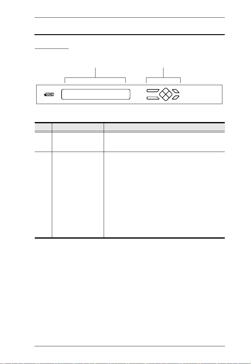
Front View
No. Component Description
1 LCD Display The LCD display shows the various options for
2 Front Panel
Pushbuttons
configuring and operating the VM0808T. For full
details, see Front Panel Operation, page 15.
Use the pushbuttons to navigate the LCD display to
configure and operate the VM0808T.
MENU – Press to invoke the Main Menu
AUDIO – Press to invoke the Audio page
ESC – Press to cancel the current selection
ENTER – Press to confirm the current selection
Use the directional pushbuttons to navigate up,
down, left, and right within the LCD display.
For full details, see Front Panel Operation, page 15.
Note: The MENU and AUDIO front panel pushbuttons
have built-in LEDs that light to indicate they have been
selected.
5
VM0808T User Manual
1234 5 6 7
8 9 10 11 12
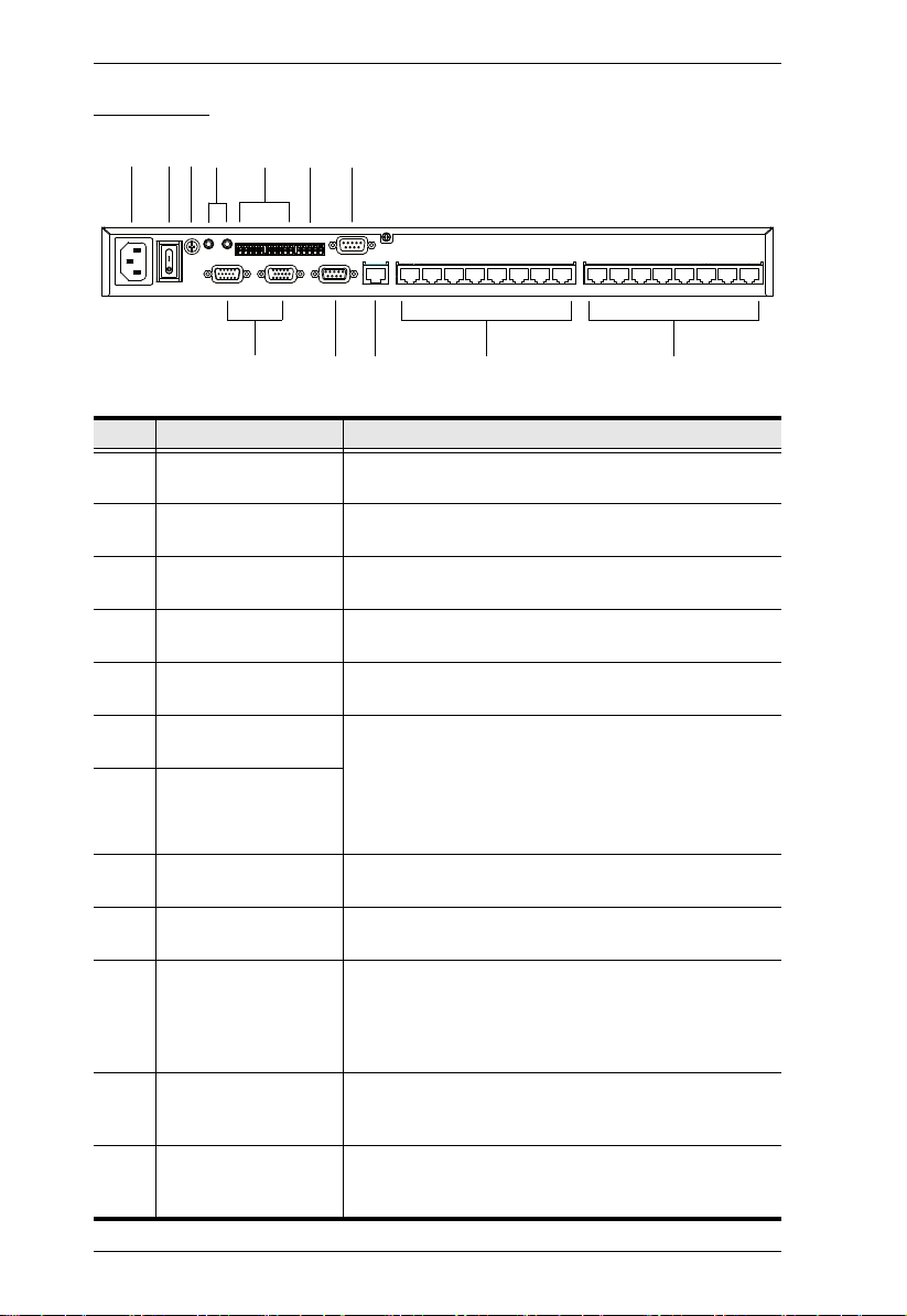
Rear View
No. Component Description
1 Power Socket This is a standard 3-pin AC power socket. The power
2 Power Switch This is a standard rocker switch that powers the unit
3 Grounding Terminal The grounding wire attaches here. See Grounding,
4 Local Stereo Audio
In / Out Ports
5 Local Balanced Audio
In / Out Ports
6 RS-485 / RS-422
Serial Port
7 RS-232 Serial Control
Port (Female)
8 Local Video In / Out
Ports
9 RS-232 Serial
Channel Port (Male)
10 Ethernet Port In order to access the VM0808T’s Browser Graphical
11 Cat 5 In Ports Use Cat 5e/6 cable to connect these ports to up to 8
12 Cat 5 Out Ports Use Cat 5e/6 cable to connect these ports to up to 8
cord from an AC source plugs in here.
on and off.
page 9, for further details.
These ports are for the local stereo audio source and
speakers.
These ports are for the local balanced audio source
and speakers.
These serial ports, comprising of one 5-pole captive
screw connector (RS-485 / RS-422) and one DB 9
(RS-232), are for serial control of the VM0808T.
Please download the appropriate software AP from
our website (www.aten.com) and reference the
Browser GUI chapter for operation (See p. 29)
These VGA ports are for connecting your local input
source and your local display.
RS-232 serial devices – such as touchscreens and
barcode scanners – plug into this port.
User Interface (GUI), the VM0808T must be
connected to your network. The cable that connects
the VM0808T to your LAN/WAN plugs in here. See
Cable Connection, page 11, for further details
VE500T transmitters. See Cable Connection, page 11,
for further details.
VE500R / VE500RQ receivers. See Cable Connection,
page 11, for further details.
6
Chapter 2
1. Important safety information regarding the placement of this
device is provided on page 49. Please review it before
proceeding.
2. Make sure that the power to all devices connected to the
installation are turned off. You must unplug the power cords of
any computers that have the Keyboard Power On function.
Hardware Setup
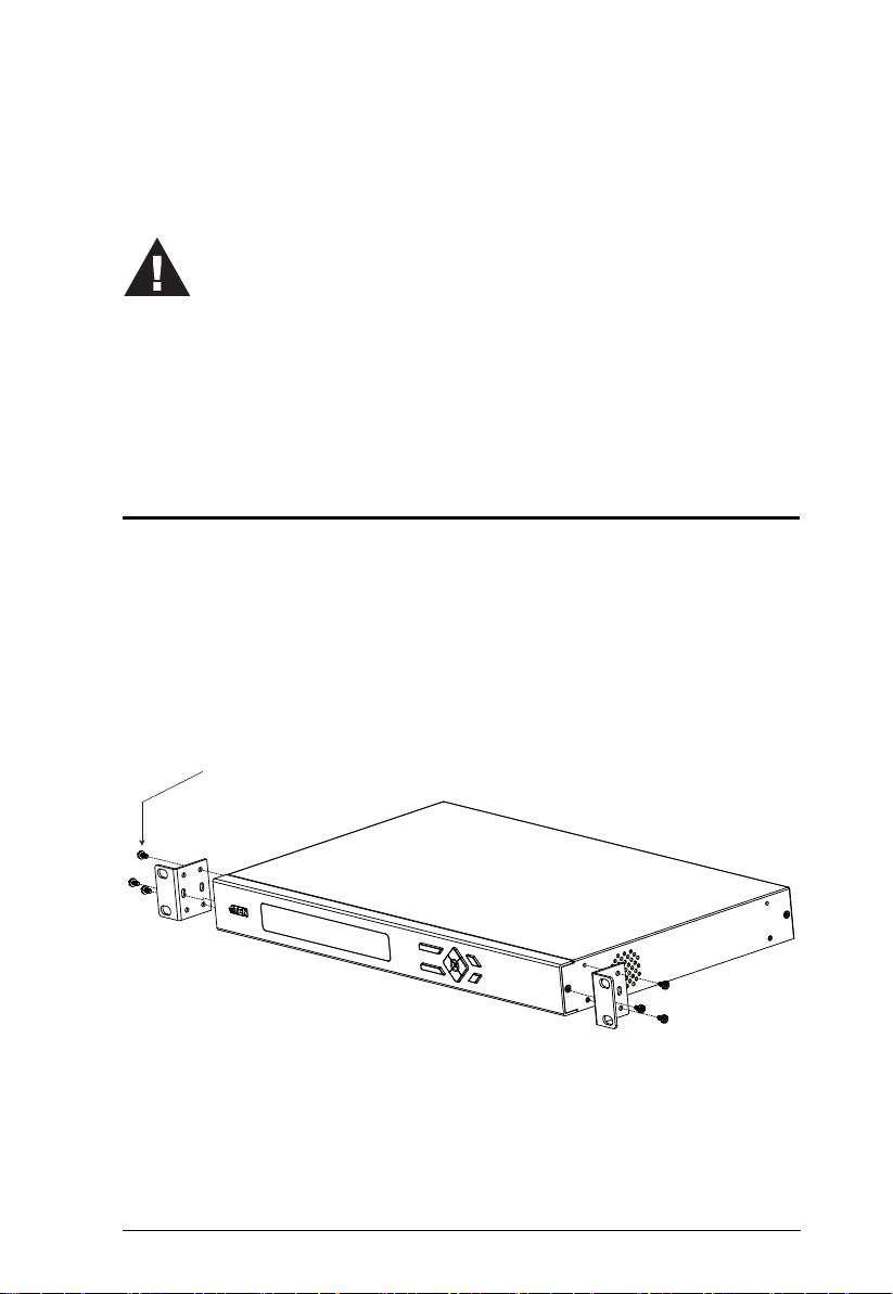
Rack Mounting
The VM0808T can be mounted in a 19” (1U) system rack. For the most
convenient front panel pushbutton configuration and operation at the local site,
mount the unit at the front of the rack, as follows:
1. Use the M3 x 8 Phillips head hex screws supplied with the Rack Mount
Kit to screw the rack mounting brackets onto the front of the unit.
Phillips head hex
M3 x 8
(Continues on next page.)
7
VM0808T User Manual
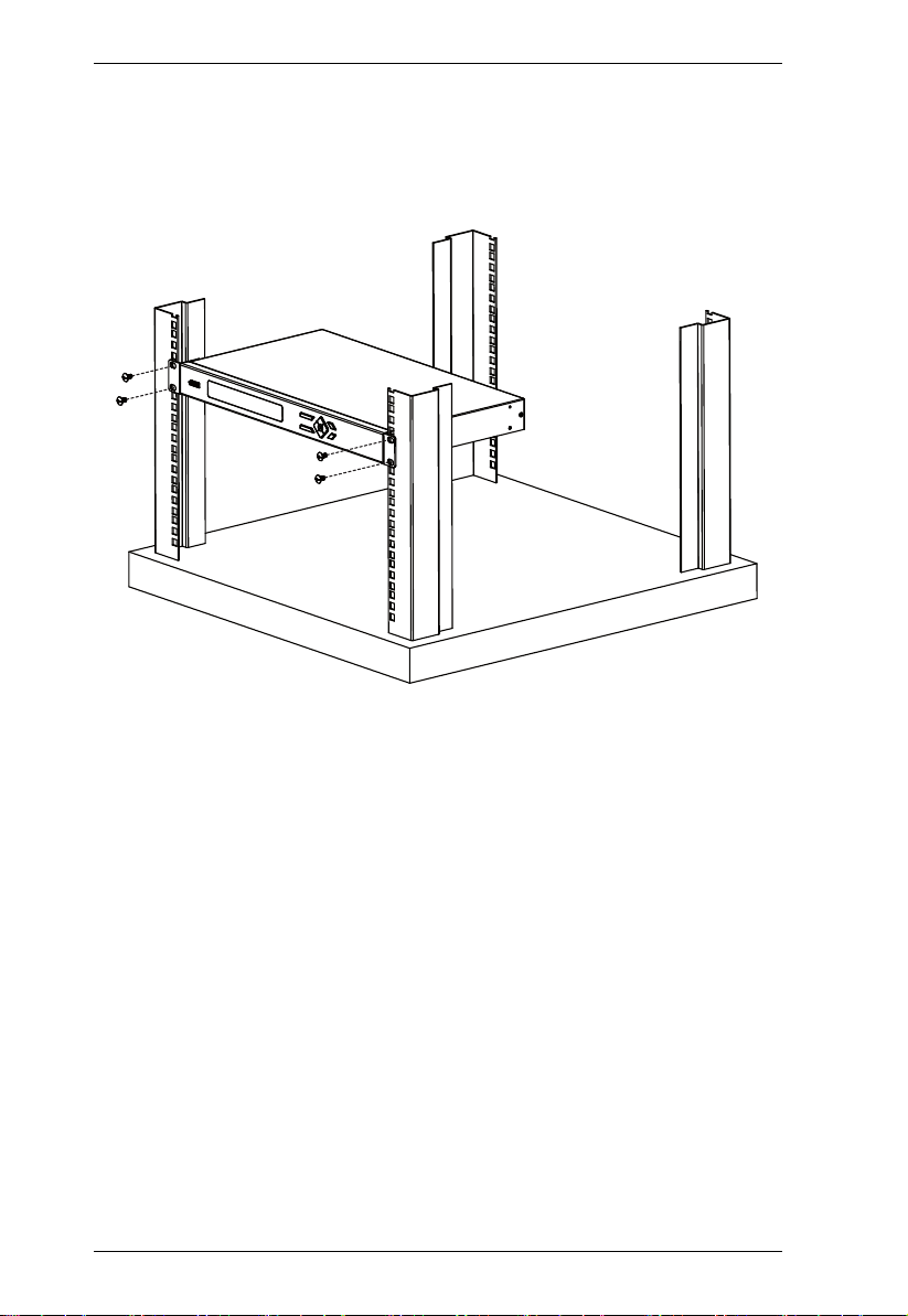
2. Position the unit in the front of the rack and align the holes in the mounting
brackets with the holes in the rack.
3. Screw the mounting brackets to the rack.
8
Chapter 2. Hardware Setup
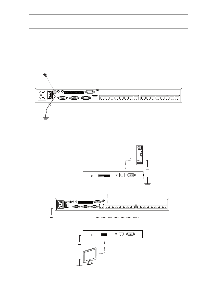
Grounding
To prevent damage to your installation, it is important that all devices are
properly grounded.
1. Use a grounding wire to ground the VM0808T by connecting one end of
the wire to the grounding terminal, and the other end of the wire to a
suitable grounded object.
2. Make sure that all devices in your VM0808T installation, including
transmitters and receivers, are properly grounded.
(Continues on next page.)
9
VM0808T User Manual
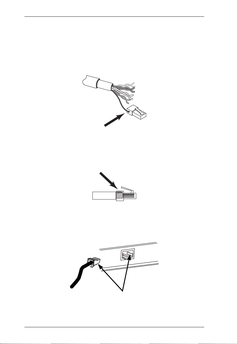
3. For increased grounding protection, use STP (shielded twisted pair) cable
to connect the Local and Remote Units. There are two methods that can be
used:
a) In addition to the eight paired wires, STP cable also contains a
grounding wire. Solder this wire to the RJ-45 connector as shown in the
diagram below:
b) The second method is to use the STP cable shielding for grounding. In
this case, make sure that the shielding makes tight contact with the top
inside of the RJ-45 connector as shown in the diagram below:
In either case, make sure that the sides of the RJ-45 connector make tight
contact with the grounding contacts on the sides of the RJ-45 socket as
shown in the diagram below:
10
 Loading...