

8x8 Video Matrix Switch + Audio
VM0808
User Manual
www.aten.com

VM0808 User Manual
FCC Information
This is an FCC Class A product. In a domestic environment this product may
cause radio interference in which case the user may be required to take
adequate measures.
This equipment has been tested and found to comply with the limits for a Class
A digital device, pursuant to Part 15 of the FCC Rules. These limits are
designed to provide reasonable protection against harmful interference when
the equipment is operated in a commercial environment. This equipment
generates, uses and can radiate radio frequency energy and, if not installed and
used in accordance with the instruction manual, may cause harmful
interference to radio communications. Operation of this equipment in a
residential area is likely to cause harmful interference in which case the user
will be required to correct the interference at his own expense.
RoHS
This product is RoHS compliant.
Safety
This product has been classified as Information Technology Equipment.
SJ/T 11364-2006
The following contains information that relates to China.
ii

VM0808 User Manual
User Information
Online Registration
Be sure to register your product at our online support center:
International http://support.aten.com
North America http://www.aten-usa.com/product_registration
Telephone Support
For telephone support, call this number:
International 886-2-8692-6959
China 86-10-5255-0110
Japan 81-3-5615-5811
Korea 82-2-467-6789
North America 1-888-999-ATEN ext 4988
United Kingdom 44-8-4481-58923
User Notice
All information, documentation, and specifications contained in this manual
are subject to change without prior notification by the manufacturer. The
manufacturer makes no representations or warranties, either expressed or
implied, with respect to the contents hereof and specifically disclaims any
warranties as to merchantability or fitness for any particular purpose. Any of
the manufacturer's software described in this manual is sold or licensed as is.
Should the programs prove defective following their purchase, the buyer (and
not the manufacturer, its distributor, or its dealer), assumes the entire cost of all
necessary servicing, repair and any incidental or consequential damages
resulting from any defect in the software.
The manufacturer of this system is not responsible for any radio and/or TV
interference caused by unauthorized modifications to this device. It is the
responsibility of the user to correct such interference.
The manufacturer is not responsible for any damage incurred in the operation
of this system if the correct operational voltage setting was not selected prior
to operation. PLEASE VERIFY THAT THE VOLTAGE SETTING IS
CORRECT BEFORE USE.
iii

VM0808 User Manual
© Copyright 2012 ATEN® International Co., Ltd.
Manual Date: 2012-11-14
ATEN and the ATEN logo are registered trademarks of ATEN International Co., Ltd. All rights reserved.
All other brand names and trademarks are the registered property of their respective owners.
Package Contents
The VM0808 package consists of:
1 VM0808 8x8 Video Matrix Switch
1Power Cord
1 IR Remote Control
1 IR Receiver
1 Mounting Kit
1 User Instructions*
Check to make sure that all the components are present and that nothing got
damaged in shipping. If you encounter a problem, contact your dealer.
Read this manual thoroughly and follow the installation and operation
procedures carefully to prevent any damage to the unit, and/or any of the
devices connected to it.
* Features may have been added to the VM0808 since this manual was
published. Please visit our website to download the most up-to-date version.
iv

VM0808 User Manual
Contents
FCC Information . . . . . . . . . . . . . . . . . . . . . . . . . . . . . . . . . . . . . . . . . . . . . ii
RoHS. . . . . . . . . . . . . . . . . . . . . . . . . . . . . . . . . . . . . . . . . . . . . . . . . . . . . . ii
Safety . . . . . . . . . . . . . . . . . . . . . . . . . . . . . . . . . . . . . . . . . . . . . . . . . . . . . ii
SJ/T 11364-2006. . . . . . . . . . . . . . . . . . . . . . . . . . . . . . . . . . . . . . . . . . . . . ii
User Information . . . . . . . . . . . . . . . . . . . . . . . . . . . . . . . . . . . . . . . . . . . . .iii
Online Registration . . . . . . . . . . . . . . . . . . . . . . . . . . . . . . . . . . . . . . . .iii
Telephone Support . . . . . . . . . . . . . . . . . . . . . . . . . . . . . . . . . . . . . . . .iii
User Notice . . . . . . . . . . . . . . . . . . . . . . . . . . . . . . . . . . . . . . . . . . . . . .iii
Package Contents . . . . . . . . . . . . . . . . . . . . . . . . . . . . . . . . . . . . . . . . . . iv
Contents . . . . . . . . . . . . . . . . . . . . . . . . . . . . . . . . . . . . . . . . . . . . . . . . . . . v
About this Manual . . . . . . . . . . . . . . . . . . . . . . . . . . . . . . . . . . . . . . . . . . vii
Conventions . . . . . . . . . . . . . . . . . . . . . . . . . . . . . . . . . . . . . . . . . . . . . . .viii
Product Information. . . . . . . . . . . . . . . . . . . . . . . . . . . . . . . . . . . . . . . . . .viii
1. Introduction
Overview . . . . . . . . . . . . . . . . . . . . . . . . . . . . . . . . . . . . . . . . . . . . . . . . . . .1
Features . . . . . . . . . . . . . . . . . . . . . . . . . . . . . . . . . . . . . . . . . . . . . . . . . . .2
Requirements . . . . . . . . . . . . . . . . . . . . . . . . . . . . . . . . . . . . . . . . . . . . . . . 3
Source Devices . . . . . . . . . . . . . . . . . . . . . . . . . . . . . . . . . . . . . . . . . .3
Display Devices . . . . . . . . . . . . . . . . . . . . . . . . . . . . . . . . . . . . . . . . . .3
Cables . . . . . . . . . . . . . . . . . . . . . . . . . . . . . . . . . . . . . . . . . . . . . . . . .3
Source Device Operating Systems . . . . . . . . . . . . . . . . . . . . . . . . . . . 4
Components . . . . . . . . . . . . . . . . . . . . . . . . . . . . . . . . . . . . . . . . . . . . . . . . 5
Front View . . . . . . . . . . . . . . . . . . . . . . . . . . . . . . . . . . . . . . . . . . . . . .5
Rear View . . . . . . . . . . . . . . . . . . . . . . . . . . . . . . . . . . . . . . . . . . . . . . .6
IR Remote Control . . . . . . . . . . . . . . . . . . . . . . . . . . . . . . . . . . . . . . . . 7
2. Hardware Setup
Rack Mounting . . . . . . . . . . . . . . . . . . . . . . . . . . . . . . . . . . . . . . . . . . . . . . 8
Cable Connections . . . . . . . . . . . . . . . . . . . . . . . . . . . . . . . . . . . . . . . . . .10
3. Operation
Overview . . . . . . . . . . . . . . . . . . . . . . . . . . . . . . . . . . . . . . . . . . . . . . . . . .11
Front Panel Operation. . . . . . . . . . . . . . . . . . . . . . . . . . . . . . . . . . . . . . . .11
Basic Navigation . . . . . . . . . . . . . . . . . . . . . . . . . . . . . . . . . . . . . . . . .11
Menu Organization . . . . . . . . . . . . . . . . . . . . . . . . . . . . . . . . . . . . . . .12
Enter Password . . . . . . . . . . . . . . . . . . . . . . . . . . . . . . . . . . . . . . . . .13
Main Screen . . . . . . . . . . . . . . . . . . . . . . . . . . . . . . . . . . . . . . . . . . . .14
Video In Selection . . . . . . . . . . . . . . . . . . . . . . . . . . . . . . . . . . . . .14
Independent Audio In Selection . . . . . . . . . . . . . . . . . . . . . . . . . . . . .15
Set Serial Port . . . . . . . . . . . . . . . . . . . . . . . . . . . . . . . . . . . . . . . . . .16
Default Serial Settings . . . . . . . . . . . . . . . . . . . . . . . . . . . . . . . . . .16
Baud Rate . . . . . . . . . . . . . . . . . . . . . . . . . . . . . . . . . . . . . . . . . . .16
v

VM0808 User Manual
Exit . . . . . . . . . . . . . . . . . . . . . . . . . . . . . . . . . . . . . . . . . . . . . . . . 17
Operation Mode . . . . . . . . . . . . . . . . . . . . . . . . . . . . . . . . . . . . . . . . . 18
Power on Detection . . . . . . . . . . . . . . . . . . . . . . . . . . . . . . . . . . . . 18
EDID . . . . . . . . . . . . . . . . . . . . . . . . . . . . . . . . . . . . . . . . . . . . . . . 19
Security Mode . . . . . . . . . . . . . . . . . . . . . . . . . . . . . . . . . . . . . . . . . . 20
Password Settings. . . . . . . . . . . . . . . . . . . . . . . . . . . . . . . . . . . . . 20
Save / Load Profile . . . . . . . . . . . . . . . . . . . . . . . . . . . . . . . . . . . . . . . 22
Profile Selection . . . . . . . . . . . . . . . . . . . . . . . . . . . . . . . . . . . . . . . . . 23
Remote Control Operation . . . . . . . . . . . . . . . . . . . . . . . . . . . . . . . . . . . . 26
Change the Input source of an Output port . . . . . . . . . . . . . . . . . . . . 26
Power on/off individual Output displays . . . . . . . . . . . . . . . . . . . . . . . 26
Power on/off all Output displays . . . . . . . . . . . . . . . . . . . . . . . . . . . . . 27
4. RS-232 Commands
Serial Control Protocol Commands . . . . . . . . . . . . . . . . . . . . . . . . . . . . . 28
Configuring the Serial Port . . . . . . . . . . . . . . . . . . . . . . . . . . . . . . . . . 28
Switch Port Commands: . . . . . . . . . . . . . . . . . . . . . . . . . . . . . . . . . . . 28
EDID Commands: . . . . . . . . . . . . . . . . . . . . . . . . . . . . . . . . . . . . . . . . 30
Mute Commands: . . . . . . . . . . . . . . . . . . . . . . . . . . . . . . . . . . . . . . . . 31
Save / Load Profile Commands: . . . . . . . . . . . . . . . . . . . . . . . . . . . . . 32
Appendix
Safety Instructions . . . . . . . . . . . . . . . . . . . . . . . . . . . . . . . . . . . . . . . . . . 34
General . . . . . . . . . . . . . . . . . . . . . . . . . . . . . . . . . . . . . . . . . . . . . . . 34
Rack Mounting . . . . . . . . . . . . . . . . . . . . . . . . . . . . . . . . . . . . . . . . . . 36
Technical Support . . . . . . . . . . . . . . . . . . . . . . . . . . . . . . . . . . . . . . . . . . 37
International . . . . . . . . . . . . . . . . . . . . . . . . . . . . . . . . . . . . . . . . . . . . 37
North America . . . . . . . . . . . . . . . . . . . . . . . . . . . . . . . . . . . . . . . . . . 37
Specifications . . . . . . . . . . . . . . . . . . . . . . . . . . . . . . . . . . . . . . . . . . . . . . 38
Limited Warranty. . . . . . . . . . . . . . . . . . . . . . . . . . . . . . . . . . . . . . . . . . . . 39
vi

VM0808 User Manual
About this Manual
This User Manual is provided to help you get the most from your VM0808
system. It covers all aspects of installation, configuration and operation. An
overview of the information found in the manual is provided below.
Chapter 1, Introduction, introduces you to the VM0808 system. Its
purpose, features and benefits are presented, and its front/back panel, and
remote control components are described.
Chapter 2, Hardware Setup, describes how to set up your VM0808
installation and all the necessary steps.
Chapter 3, Operation, explains the fundamental concepts involved in
operating the VM0808 via the front panel LCD display, and with the IR remote
control.
Chapter 4, RS-232 Protocol Commands, provides a complete list of the
serial control protocol commands used when utilizing the RS-232 Serial Port
so that an extra source device can function further as transmitter and receiver.
An Appendix, provides specifications and other technical information
regarding the VM0808.
vii

VM0808 User Manual
Conventions
This manual uses the following conventions:
Monospaced Indicates text that you should key in.
[ ] Indicates keys you should press. For example, [Enter] means to
press the Enter key. If keys need to be chorded, they appear
together in the same bracket with a plus sign between them:
[Ctrl+Alt].
1. Numbered lists represent procedures with sequential steps.
♦ Bullet lists provide information, but do not involve sequential steps.
→ Indicates selecting the option (on a menu or dialog box, for
example), that comes next. For example, Start
open the Start menu, and then select Run.
Indicates critical information.
Product Information
→ Run means to
For information about all ATEN products and how they can help you connect
without limits, visit ATEN on the Web or contact an ATEN Authorized
Reseller. Visit ATEN on the Web for a list of locations and telephone numbers:
International http://www.aten.com
North America http://www.aten-usa.com
viii

Chapter 1
Introduction
Overview
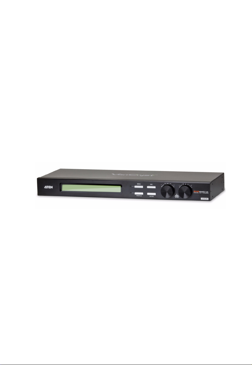
The ATEN VanCryst VM0808 8x8 Video Matrix Switch + Audio allows you
to connect eight VGA source devices to eight VGA monitors, displays, or
projectors- at the same time. It’s vastly unique features include: fast source/
display switching, IR remote control switching, unlimited matrix connections,
Power On Detection for automatic display-loss prevention, RS-232 for highend controllers, and independent audio matrix capabilities.
The VM0808 is a smart audio/video solution that offers an easy and affordable
way to route any of 8 audio/video sources to any of 8 audio/displays, in any
matrix combination.
As a Matrix Switch, each input can be independently connected to any or all
outputs, and the audio inputs from each source device can also be switched
independently, giving you the ultimate in flexibility and control in any multidisplay audio/video installation.
Furthermore, for more complete systems integrations, the VM0808’s includes
a built-in RS-232 port that allows the switch to be controlled through a highend controller or PC.
1

VM0808 User Manual
Features
Connects any of 8 VGA Video + Audio inputs to any of 8 VGA Video +
Audio outputs
Long signal range – supports up to 30 meters
Easily switch between multiple sources and multiple displays
Operation:
Front panel LCD display and pushbuttons
Tuner Dials with pushbutton
RS-232 Serial controller
IR Remote Control
Superior video quality – up to 1920 x 1440; VGA, SVGA, SXGA, UXGA,
and WUXGA (1920 x 1200)
Features EDID expert technology to set up different video configurations
via different EDID modes
Supports up to 500 MHz bandwidth
Supports stereo audio
Independent switching of audio and video sources – each input can be
independently connected to any or all outputs for flexibility
Power On Detection - If one of the video sources is powered off the
VM0808 automatically switches to the next powered-on source
Cascade Additional VM0808 Units up to three levels
Rack Mountable
All metal casing
Note: The VM0808 RS-232 AP and GUI instructions can be downloaded
from the ATEN website: www.aten.com.
2

Chapter 1. Introduction
Requirements
The following equipment is required for a complete VM0808 installation
Source Devices
Computer or A/V source device with VGA and stereo output
Display Devices
A VGA, SVGA, XGA, SXGA, UXGA, WUXGA, or multisync display
device with an HDB-15 connector
Stereo speakers
Cables
Use VGA/Audio/RS-232 cables to connect the computer (or other audio/
video source device) to the VM0808
Note: Cables are not provided in the VM0808 package.
3

VM0808 User Manual
Source Device Operating Systems
Supported operating systems are shown in the table, below:
OS Ver sio n
Windows 2000 and higher
Linux RedHat 6.0 and higher
SuSE 8.2 and higher
Mandriva (Mandrake) 9.0 and higher
UNIX AIX 4.3 and higher
FreeBSD 3.51 and higher
Sun Solaris 8 and higher
Novell Netware 5.0 and higher
Mac OS 9 and higher
DOS 6.2 and higher
4
Chapter 1. Introduction
1
2
MENU
ESC
PROFILE
ENTER
IN
OUT
Components
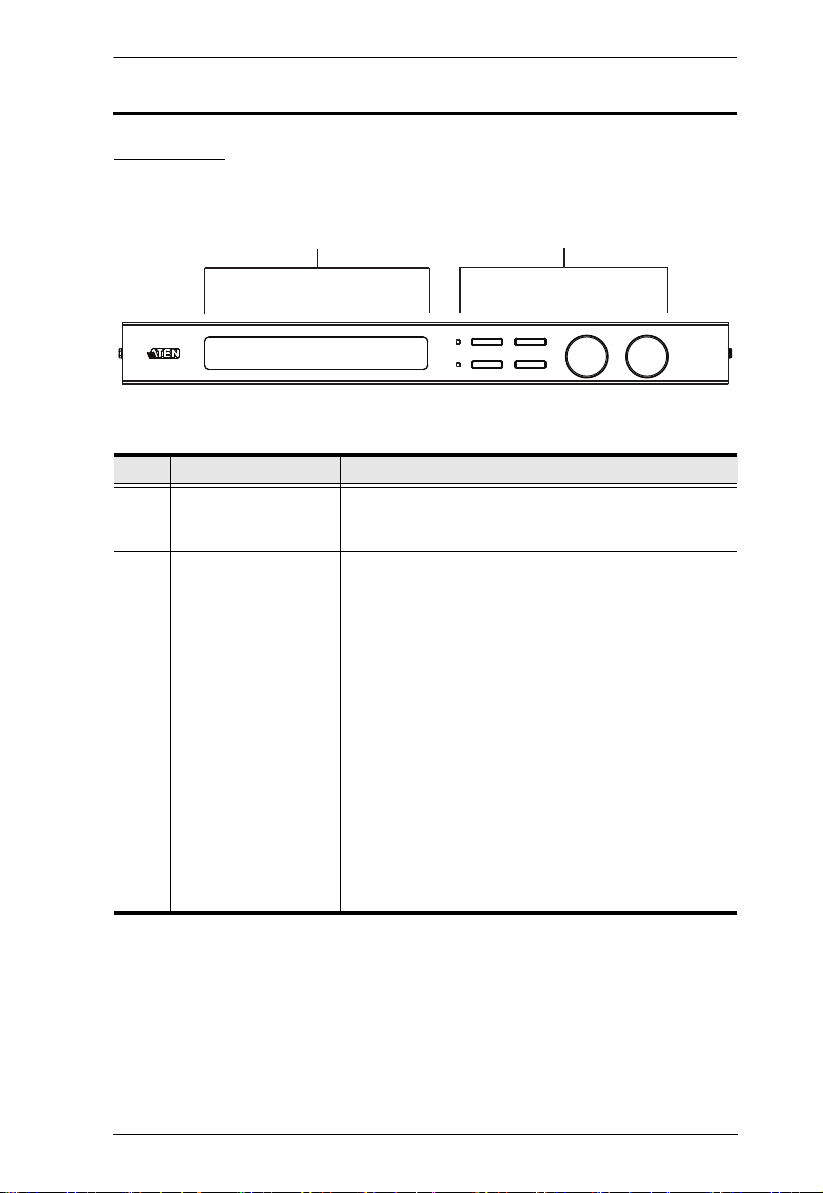
Front View
No. Component Description
1 LCD Display The LCD display shows the various options for
2 Front Panel
Pushbuttons and
Tuner Dials
configuring and operating the VM0808. For full details,
see Front Panel Operation, page 11.
Use the pushbuttons to navigate the LCD display to
configure and operate the VM0808.
MENU – Press to invoke the Menu page/Main
Screen
PROFILE – Press to switch between the video
source Profile Selection list
ESC – Press to cancel the current selection or exit
without saving changes
ENTER – Press to confirm the current selection
Tuner Dials - IN & OUT to navigate up, down, left,
and right or scroll selected options within the LCD
display.
For full details, see Front Panel Operation, page 11.
Note: The MENU and PROFILE front panel
pushbuttons have built-in LEDs that light to indicate
they have been selected.
5

VM0808 User Manual
1
2
3
4
56
Rear View
No. Component Description
1 Power Socket This is a standard 3-pin AC power socket. The power
2 Power Switch This is a standard rocker switch that powers the unit
3 External IR Receiver
Port
4 RS-232 Serial Port This serial remote port is for input source selection and
5 Audio/Video Input
Ports
6 Audio/Video Output
Ports
cord from an AC source plugs in here.
on and off.
3.5 mm Mini Stereo Jack which connects the IR
Receiver unit included with your product.
high-end system control.
The VGA ports are for connecting your input source.
The Mini Stereo Jack ports are for the audio source.
The VGA ports are for connecting your output
displays. The Mini Stereo Jack ports are for the audio
speakers.
6

IR Remote Control
1
2
3
Chapter 1. Introduction
No. Component Description
1 Power ON/OFF Use the ON and OFF pushbuttons to turn the Output
2 Output Pushbuttons
1–8
3 Input Pushbuttons
1–8
displays on or off- by individual port, or all ports. (see
Remote Control Operation, page 26)
Output display Pushbutton 1–8 to change Input source
for Output displays. (see Remote Control Operation,
page 26)
Input source Pushbutton 1–8 to change Input source
of an Output display. (see Remote Control Operation,
page 26)
7
 Loading...