

ATEN Control System
User Manual
www.aten.com

ATEN Control System User Manual
EMC Information
FEDERAL COMMUNICATIONS COMMISSION INTERFERENCE
STATEMENT
This equipment has been tested and found to comply with the limits for a Class A digital
device, pursuant to Part 15 of the FCC Rules. These limits are designed to provide
reasonable protection against harmful interference when the equipment is operated in a
commercial environment. This equipment generates, uses, and can radiate radio
frequency energy and, if not installed and used in accordance with the instruction
manual, may cause harmful interference to radio communications. Operation of this
equipment in a residential area is likely to cause harmful interference in which case the
user will be required to correct the interference at his own expense.
FCC Caution: Any changes or modifications not expressly approved by the party
responsible for compliance could void the user's authority to operate this equipment.
Warning: Operation of this equipment in a residential environment could cause radio
interference.
KCC Statement
유선 제품용 / A 급 기기 ( 업무용 방송 통신 기기 )
이 기기는 업무용 (A 급 ) 전자파적합기기로서 판매자 또는 사용자는 이
점을 주의하시기 바라며 , 가정 외의 지역에서 사용하는 것을 목적으로
합니다 .
RoHS
This product is RoHS compliant.
Safety
This product has been classified as Information Technology Equipment.
ii

ATEN Control System User Manual
User Information
Online Registration
Be sure to register your product at our online support center:
International http://eservice.aten.com
Telephone Support
For telephone support, call this number:
International 886-2-8692-6959
China 86-400-810-0-810
Japan 81-3-5615-5811
Korea 82-2-467-6789
North America 1-888-999-ATEN ext 4988
1-949-428-1111
User Notice
All information, documentation, and specifications contained in this manual
are subject to change without prior notification by the manufacturer. The
manufacturer makes no representations or warranties, either expressed or
implied, with respect to the contents hereof and specifically disclaims any
warranties as to merchantability or fitness for any particular purpose. Any of
the manufacturer's software described in this manual is sold or licensed as is.
Should the programs prove defective following their purchase, the buyer (and
not the manufacturer, its distributor, or its dealer), assumes the entire cost of all
necessary servicing, repair and any incidental or consequential damages
resulting from any defect in the software.
The manufacturer of this system is not responsible for any radio and/or TV
interference caused by unauthorized modifications to this device. It is the
responsibility of the user to correct such interference.
The manufacturer is not responsible for any damage incurred in the operation
of this system if the correct operational voltage setting was not selected prior
to operation. PLEASE VERIFY THAT THE VOLTAGE SETTING IS
CORRECT BEFORE USE.
iii

ATEN Control System User Manual
Package Contents
VK0100
The VK0100 package consists of:
1 VK0100 8-Button Control Pad (US, 1 Gang)
1 Button Pack
6 Terminal Blocks
1 Faceplate
1 User Instructions*
VK0200
The VK0200 package consists of:
1 VK0200 12-Button Control Pad (EU, 2 Gang)
1 Button Pack
6 Terminal Blocks
1 Faceplate
1 User Instructions*
VK1100
The VK1100 package consists of:
1 VK1100 Compact Control Box
4 Terminal Blocks
1Power Cord
1 User Instructions*
VK2100
The VK2100 package consists of:
1 VK2100 Control Box
1 Rack Mount Kit
9 Terminal Blocks
1Power Cord
1 User Instructions*
iv

ATEN Control System User Manual
Note:
Read this manual thoroughly and follow the installation and operation
procedures carefully to prevent any damage to the ATEN controller and
other connected devices.
The VK2100 product firmware may have been updated with new features
after the release of this manual. For an up-to-date VK2100 user manual,
visit http://www.aten.com/global/en/
v

ATEN Control System User Manual
Table of Contents
EMC Information. . . . . . . . . . . . . . . . . . . . . . . . . . . . . . . . . . . . . . . . . . . . . ii
Safety . . . . . . . . . . . . . . . . . . . . . . . . . . . . . . . . . . . . . . . . . . . . . . . . . . . . . ii
User Information . . . . . . . . . . . . . . . . . . . . . . . . . . . . . . . . . . . . . . . . . . . .iii
Telephone Support . . . . . . . . . . . . . . . . . . . . . . . . . . . . . . . . . . . . . . . .iii
Package Contents . . . . . . . . . . . . . . . . . . . . . . . . . . . . . . . . . . . . . . . . . . .iv
VK0100 . . . . . . . . . . . . . . . . . . . . . . . . . . . . . . . . . . . . . . . . . . . . . . . . .iv
VK0200 . . . . . . . . . . . . . . . . . . . . . . . . . . . . . . . . . . . . . . . . . . . . . . . . .iv
VK1100 . . . . . . . . . . . . . . . . . . . . . . . . . . . . . . . . . . . . . . . . . . . . . . . . .iv
VK2100 . . . . . . . . . . . . . . . . . . . . . . . . . . . . . . . . . . . . . . . . . . . . . . . . .iv
Table of Contents . . . . . . . . . . . . . . . . . . . . . . . . . . . . . . . . . . . . . . . . . . .vi
About this Manual . . . . . . . . . . . . . . . . . . . . . . . . . . . . . . . . . . . . . . . . . . . x
Conventions . . . . . . . . . . . . . . . . . . . . . . . . . . . . . . . . . . . . . . . . . . . . . . . .xi
Terminology . . . . . . . . . . . . . . . . . . . . . . . . . . . . . . . . . . . . . . . . . . . . . . . xii
Product Information . . . . . . . . . . . . . . . . . . . . . . . . . . . . . . . . . . . . . . . . . xii
1. Introduction
Overview. . . . . . . . . . . . . . . . . . . . . . . . . . . . . . . . . . . . . . . . . . . . . . . . . . . 1
Benefits . . . . . . . . . . . . . . . . . . . . . . . . . . . . . . . . . . . . . . . . . . . . . . . . . . . 3
Intelligent Control . . . . . . . . . . . . . . . . . . . . . . . . . . . . . . . . . . . . . . . . . 3
Features . . . . . . . . . . . . . . . . . . . . . . . . . . . . . . . . . . . . . . . . . . . . . . . . . . . 5
ATEN Control Pad . . . . . . . . . . . . . . . . . . . . . . . . . . . . . . . . . . . . . . . . 6
ATEN Configurator . . . . . . . . . . . . . . . . . . . . . . . . . . . . . . . . . . . . . . . . 7
ATEN Control System App . . . . . . . . . . . . . . . . . . . . . . . . . . . . . . . . . . 7
ATEN Keypads . . . . . . . . . . . . . . . . . . . . . . . . . . . . . . . . . . . . . . . . . . . 8
Requirements . . . . . . . . . . . . . . . . . . . . . . . . . . . . . . . . . . . . . . . . . . . . . . 9
Accessories . . . . . . . . . . . . . . . . . . . . . . . . . . . . . . . . . . . . . . . . . . . . . . . 10
2. Hardware Setup
ATEN Control Box . . . . . . . . . . . . . . . . . . . . . . . . . . . . . . . . . . . . . . . . . . 11
Panel Components . . . . . . . . . . . . . . . . . . . . . . . . . . . . . . . . . . . . . . . 11
VK2100 Front View . . . . . . . . . . . . . . . . . . . . . . . . . . . . . . . . . . . 11
VK2100 Rear View . . . . . . . . . . . . . . . . . . . . . . . . . . . . . . . . . . . . 13
VK1100 Front View . . . . . . . . . . . . . . . . . . . . . . . . . . . . . . . . . . . 14
VK1100 Rear View . . . . . . . . . . . . . . . . . . . . . . . . . . . . . . . . . . . . 15
Rack Mounting the ATEN Control Box . . . . . . . . . . . . . . . . . . . . . . . . 16
VK2100 . . . . . . . . . . . . . . . . . . . . . . . . . . . . . . . . . . . . . . . . . . . . . 16
VK1100 . . . . . . . . . . . . . . . . . . . . . . . . . . . . . . . . . . . . . . . . . . . . . 17
Control Box Connections . . . . . . . . . . . . . . . . . . . . . . . . . . . . . . . . . . 19
12VDC Power Output . . . . . . . . . . . . . . . . . . . . . . . . . . . . . . . . . . . . . 22
Relay . . . . . . . . . . . . . . . . . . . . . . . . . . . . . . . . . . . . . . . . . . . . . . . . . 26
IR / Serial . . . . . . . . . . . . . . . . . . . . . . . . . . . . . . . . . . . . . . . . . . . . . . 27
One IR Transmitter . . . . . . . . . . . . . . . . . . . . . . . . . . . . . . . . . . . . 28
Two IR Transmitters . . . . . . . . . . . . . . . . . . . . . . . . . . . . . . . . . . . 28
vi

ATEN Control System User Manual
Digital I/O . . . . . . . . . . . . . . . . . . . . . . . . . . . . . . . . . . . . . . . . . . . . . .29
RS-232 . . . . . . . . . . . . . . . . . . . . . . . . . . . . . . . . . . . . . . . . . . . . . . . .31
RS-232 / 422 / 485 . . . . . . . . . . . . . . . . . . . . . . . . . . . . . . . . . . . . . . . 32
Ethernet . . . . . . . . . . . . . . . . . . . . . . . . . . . . . . . . . . . . . . . . . . . . . . .33
ATEN Control Pad. . . . . . . . . . . . . . . . . . . . . . . . . . . . . . . . . . . . . . . . . . .34
Installing the Control Pads . . . . . . . . . . . . . . . . . . . . . . . . . . . . . . . . . 36
Installation Steps . . . . . . . . . . . . . . . . . . . . . . . . . . . . . . . . . . . . . .36
RS-232 Serial Connection . . . . . . . . . . . . . . . . . . . . . . . . . . . . . .41
Relay Connections . . . . . . . . . . . . . . . . . . . . . . . . . . . . . . . . . . . .42
Digital Input Device . . . . . . . . . . . . . . . . . . . . . . . . . . . . . . . . . . . . 43
Ethernet . . . . . . . . . . . . . . . . . . . . . . . . . . . . . . . . . . . . . . . . . . . .44
Accessories . . . . . . . . . . . . . . . . . . . . . . . . . . . . . . . . . . . . . . . . . . . . . . .45
ATEN Keypad . . . . . . . . . . . . . . . . . . . . . . . . . . . . . . . . . . . . . . . . . . . 46
Installation . . . . . . . . . . . . . . . . . . . . . . . . . . . . . . . . . . . . . . . . . . . 47
Component . . . . . . . . . . . . . . . . . . . . . . . . . . . . . . . . . . . . . . . . . .51
Layout Examples . . . . . . . . . . . . . . . . . . . . . . . . . . . . . . . . . . . . . . 52
3. Browser Operation
Overview . . . . . . . . . . . . . . . . . . . . . . . . . . . . . . . . . . . . . . . . . . . . . . . . . .53
Logging In . . . . . . . . . . . . . . . . . . . . . . . . . . . . . . . . . . . . . . . . . . . . . . . . .53
Dashboard . . . . . . . . . . . . . . . . . . . . . . . . . . . . . . . . . . . . . . . . . . . . . . . . 54
Settings . . . . . . . . . . . . . . . . . . . . . . . . . . . . . . . . . . . . . . . . . . . . . . . . . . 55
Licenses for Mobile Control . . . . . . . . . . . . . . . . . . . . . . . . . . . . . . . .57
Storage . . . . . . . . . . . . . . . . . . . . . . . . . . . . . . . . . . . . . . . . . . . . . . . .58
Access . . . . . . . . . . . . . . . . . . . . . . . . . . . . . . . . . . . . . . . . . . . . . . . .59
Monitor . . . . . . . . . . . . . . . . . . . . . . . . . . . . . . . . . . . . . . . . . . . . . . . . 61
Network . . . . . . . . . . . . . . . . . . . . . . . . . . . . . . . . . . . . . . . . . . . . . . . .62
Connections . . . . . . . . . . . . . . . . . . . . . . . . . . . . . . . . . . . . . . . . . . . . 63
Schedule . . . . . . . . . . . . . . . . . . . . . . . . . . . . . . . . . . . . . . . . . . . . . . .64
Security . . . . . . . . . . . . . . . . . . . . . . . . . . . . . . . . . . . . . . . . . . . . . . . 65
4. ATEN Configurator (VK6000)
Overview . . . . . . . . . . . . . . . . . . . . . . . . . . . . . . . . . . . . . . . . . . . . . . . . . .67
Installation. . . . . . . . . . . . . . . . . . . . . . . . . . . . . . . . . . . . . . . . . . . . . . . . .67
Getting Started Tasks . . . . . . . . . . . . . . . . . . . . . . . . . . . . . . . . . . . . . . . . 70
Main Page . . . . . . . . . . . . . . . . . . . . . . . . . . . . . . . . . . . . . . . . . . . . . . . .72
Menu Bar . . . . . . . . . . . . . . . . . . . . . . . . . . . . . . . . . . . . . . . . . . . . . . . . .73
Project . . . . . . . . . . . . . . . . . . . . . . . . . . . . . . . . . . . . . . . . . . . . . . . . . . .79
Device . . . . . . . . . . . . . . . . . . . . . . . . . . . . . . . . . . . . . . . . . . . . . . . . . . . 81
Adding Devices to ATEN Configurator . . . . . . . . . . . . . . . . . . . . . . . .82
The Device Configuration List . . . . . . . . . . . . . . . . . . . . . . . . . . . . . . .83
Left Sidebar . . . . . . . . . . . . . . . . . . . . . . . . . . . . . . . . . . . . . . . . . . . .84
Library . . . . . . . . . . . . . . . . . . . . . . . . . . . . . . . . . . . . . . . . . . . . . . . . 85
Device Library . . . . . . . . . . . . . . . . . . . . . . . . . . . . . . . . . . . . . . . . . .86
Properties . . . . . . . . . . . . . . . . . . . . . . . . . . . . . . . . . . . . . . . . . . . . . .87
Design . . . . . . . . . . . . . . . . . . . . . . . . . . . . . . . . . . . . . . . . . . . . . . . . . . .94
vii

ATEN Control System User Manual
Select Viewer . . . . . . . . . . . . . . . . . . . . . . . . . . . . . . . . . . . . . . . . . . . 95
Left Sidebar. . . . . . . . . . . . . . . . . . . . . . . . . . . . . . . . . . . . . . . . . . . . . 96
Viewer . . . . . . . . . . . . . . . . . . . . . . . . . . . . . . . . . . . . . . . . . . . . . 96
Pages . . . . . . . . . . . . . . . . . . . . . . . . . . . . . . . . . . . . . . . . . . . . . . 96
Right Sidebar . . . . . . . . . . . . . . . . . . . . . . . . . . . . . . . . . . . . . . . . . . . 97
Keypad . . . . . . . . . . . . . . . . . . . . . . . . . . . . . . . . . . . . . . . . . . . . . . . . 97
Page Overview . . . . . . . . . . . . . . . . . . . . . . . . . . . . . . . . . . . . . . . . . . 98
Edit . . . . . . . . . . . . . . . . . . . . . . . . . . . . . . . . . . . . . . . . . . . . . . . . . . . 99
Windows OS Button Limitation . . . . . . . . . . . . . . . . . . . . . . . . . . 100
Page Objects . . . . . . . . . . . . . . . . . . . . . . . . . . . . . . . . . . . . . . . 101
Properties . . . . . . . . . . . . . . . . . . . . . . . . . . . . . . . . . . . . . . . . . . 101
Button / Slider Bar Action . . . . . . . . . . . . . . . . . . . . . . . . . . . . . . 111
Adding Commands . . . . . . . . . . . . . . . . . . . . . . . . . . . . . . . . . . . 113
Advanced Options . . . . . . . . . . . . . . . . . . . . . . . . . . . . . . . . . . . 117
Layering Images . . . . . . . . . . . . . . . . . . . . . . . . . . . . . . . . . . . . . 130
Graphic Library . . . . . . . . . . . . . . . . . . . . . . . . . . . . . . . . . . . . . . . . . 131
Background Color . . . . . . . . . . . . . . . . . . . . . . . . . . . . . . . . . . . . 131
Button . . . . . . . . . . . . . . . . . . . . . . . . . . . . . . . . . . . . . . . . . . . . . 131
Icon . . . . . . . . . . . . . . . . . . . . . . . . . . . . . . . . . . . . . . . . . . . . . . . 132
Device Interface . . . . . . . . . . . . . . . . . . . . . . . . . . . . . . . . . . . . . 132
Library . . . . . . . . . . . . . . . . . . . . . . . . . . . . . . . . . . . . . . . . . . . . . . . . . . 133
Flag . . . . . . . . . . . . . . . . . . . . . . . . . . . . . . . . . . . . . . . . . . . . . . . . . 134
Monitor . . . . . . . . . . . . . . . . . . . . . . . . . . . . . . . . . . . . . . . . . . . . . . . 136
Condition & Action Overview. . . . . . . . . . . . . . . . . . . . . . . . . . . . 136
Creating an If Monitor . . . . . . . . . . . . . . . . . . . . . . . . . . . . . . . . . 139
Creating a Switch Monitor . . . . . . . . . . . . . . . . . . . . . . . . . . . . . 144
Creating a Bypass Monitor . . . . . . . . . . . . . . . . . . . . . . . . . . . . . 147
Macro . . . . . . . . . . . . . . . . . . . . . . . . . . . . . . . . . . . . . . . . . . . . . . . . 148
Scheduled Events . . . . . . . . . . . . . . . . . . . . . . . . . . . . . . . . . . . . . . . 150
Synced Variables . . . . . . . . . . . . . . . . . . . . . . . . . . . . . . . . . . . . . . . 151
Upload . . . . . . . . . . . . . . . . . . . . . . . . . . . . . . . . . . . . . . . . . . . . . . . . . . 156
Viewing Controller Information . . . . . . . . . . . . . . . . . . . . . . . . . . . . . 157
5. Remote PC Control Using ControlAssist
Overview. . . . . . . . . . . . . . . . . . . . . . . . . . . . . . . . . . . . . . . . . . . . . . . . . 159
Specifications . . . . . . . . . . . . . . . . . . . . . . . . . . . . . . . . . . . . . . . . . . . . . 159
Setting Up Remote PC Control . . . . . . . . . . . . . . . . . . . . . . . . . . . . . . . 161
Installing ControlAssist to a Computer . . . . . . . . . . . . . . . . . . . . . . . 161
Adding the Computer to the Control System. . . . . . . . . . . . . . . . . . . 163
Configuring a Control Interface . . . . . . . . . . . . . . . . . . . . . . . . . . . . . 165
Supported PC Control Actions . . . . . . . . . . . . . . . . . . . . . . . . . . 168
6. ATEN Control System App
Overview. . . . . . . . . . . . . . . . . . . . . . . . . . . . . . . . . . . . . . . . . . . . . . . . . 171
Installing the App . . . . . . . . . . . . . . . . . . . . . . . . . . . . . . . . . . . . . . . . . . 171
ATEN Control System App . . . . . . . . . . . . . . . . . . . . . . . . . . . . . . . . . . 172
viii

ATEN Control System User Manual
Demo . . . . . . . . . . . . . . . . . . . . . . . . . . . . . . . . . . . . . . . . . . . . . . . . . . .173
WinViewer1 / iPad / Android1 . . . . . . . . . . . . . . . . . . . . . . . . . . . . . . 173
Demo. . . . . . . . . . . . . . . . . . . . . . . . . . . . . . . . . . . . . . . . . . . . . . . . .174
Welcome . . . . . . . . . . . . . . . . . . . . . . . . . . . . . . . . . . . . . . . . . . . . . . . .176
Edit Viewer Profile . . . . . . . . . . . . . . . . . . . . . . . . . . . . . . . . . . . . . .177
Manage LAN Device . . . . . . . . . . . . . . . . . . . . . . . . . . . . . . . . . . . . 178
Controller . . . . . . . . . . . . . . . . . . . . . . . . . . . . . . . . . . . . . . . . . . .179
Set Password . . . . . . . . . . . . . . . . . . . . . . . . . . . . . . . . . . . . . . . . . . 181
Log Report . . . . . . . . . . . . . . . . . . . . . . . . . . . . . . . . . . . . . . . . . . . . 182
Report History . . . . . . . . . . . . . . . . . . . . . . . . . . . . . . . . . . . . . . . . .183
Information . . . . . . . . . . . . . . . . . . . . . . . . . . . . . . . . . . . . . . . . . . . .184
Download Viewer Profile . . . . . . . . . . . . . . . . . . . . . . . . . . . . . . . . . . . .185
Downloading Profiles . . . . . . . . . . . . . . . . . . . . . . . . . . . . . . . . . . . .186
Appendix
Safety Instructions. . . . . . . . . . . . . . . . . . . . . . . . . . . . . . . . . . . . . . . . . .187
Rack Mounting . . . . . . . . . . . . . . . . . . . . . . . . . . . . . . . . . . . . . . . . .189
Technical Support . . . . . . . . . . . . . . . . . . . . . . . . . . . . . . . . . . . . . . . . .190
Datapoint Types . . . . . . . . . . . . . . . . . . . . . . . . . . . . . . . . . . . . . . . . . . . 191
Specifications . . . . . . . . . . . . . . . . . . . . . . . . . . . . . . . . . . . . . . . . . . . . . 194
VK2100 . . . . . . . . . . . . . . . . . . . . . . . . . . . . . . . . . . . . . . . . . . . . . . . 194
VK1100 . . . . . . . . . . . . . . . . . . . . . . . . . . . . . . . . . . . . . . . . . . . . . . . 196
VK0100/VK0200 . . . . . . . . . . . . . . . . . . . . . . . . . . . . . . . . . . . . . . . .198
Limited Warranty . . . . . . . . . . . . . . . . . . . . . . . . . . . . . . . . . . . . . . . . . .200
ix

ATEN Control System User Manual
About this Manual
This user manual is provided to help you get the most from your ATEN Control
System. It covers all aspects of installation, configuration, and operation of the
ATEN controllers and their accessories, including:
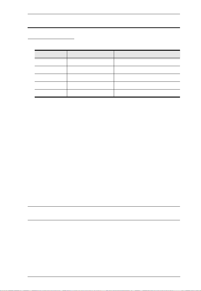
Device Category Device Model Device Name
ATEN Control Box VK1100 ATEN Compact Control Box
VK2100 ATEN Control Box
ATEN Control Pad VK0100 8-Button Control Pad (US, 1 Gang)
VK0200 12-Button Control Pad (EU, 2 Gang)
ATEN Keypad VK108US 8-Button Keypad (US, 1 Gang)
VK112EU 12-Button Keypad (EU, 2 Gang)
ATEN Extension Box VK224 4-Port Serial Expansion
VK236 6-Port IR/Serial Expansion Box
VK248 8-Channel Relay Expansion Box
An overview of the information found in the manual is provided below.
Chapter 1, Introduction
Introduces you to the ATEN Control System. Its purpose, features, and benefits
are presented, and panel components of the Control Box and Control Pad are
described.
Chapter 2, Hardware Setup
Provides the necessary steps to setup the ATEN Control System installation,
including how to wire the different types of hardware connections.
Chapter 3, Browser Operation
Provides information on Control Box and Control Pad’s web interface and how
to use it to remotely configure parts of the ATEN Control System installation.
Chapter 4, ATEN Configurator (VK6000)
Provides a complete description of the ATEN Configurator (VK6000) software
and how to use it to configure and operate the ATEN Control System.
Chapter 5, ATEN Database Generator
Provides a complete description of the Database Generator software and how
to use it to configure new devices to add to the VK6000 device library.
x

ATEN Control System User Manual
Chapter 6, Remote PC Control
Explains how to set up your computer for remote control from a licensed
device and provide a complete description of the supported control actions.
Chapter 7, ATEN Control System App
Provides a complete description of the ATEN mobile app and how to use it to
operate devices connected to the ATEN Control System.
An Appendix
Provides specifications and other technical information regarding the ATEN
Control System.
Conventions
This manual uses the following conventions:
Monospaced Indicates text that you should key in.
[ ] Indicates keys you should press. For example, [Enter] means to
press the Enter key. If keys need to be chorded, they appear
together in the same bracket with a plus sign between them:
[Ctrl+Alt].
1. Numbered lists represent procedures with sequential steps.
♦ Bullet lists provide information, but do not involve sequential steps.
→ Indicates selecting the option (on a menu or dialog box, for
example), that comes next. For example, Start
open the Start menu, and then select Run.
Indicates critical information.
→ Run means to
xi

ATEN Control System User Manual
Terminology
Ter min olo gy Description
Control Box The term is used to refer to all models of ATEN Control Box,
controller The term is used to refer to all models of ATEN Control Box
Viewer or profile A Viewer or profile is a software interface created using ATEN
project A project is a set of settings created using ATEN Configurator to
including the VK2100 Control Box and the VK1100 Compact
Control Box.
(VK1100 and VK2100) and ATEN Control Pad (VK0100 and
VK0200).
Configurator to be used on mobile devices to control devices
managed by controllers.
specify how devices are to be managed by ATEN controllers.
Product Information
For information about all ATEN products and how they can help you connect
without limits, visit ATEN on the Web or contact an ATEN Authorized
Reseller. Visit ATEN on the Web for a list of locations and telephone numbers:
International http://www.aten.com
North America http://www.aten-usa.com
xii

Chapter 1
Introduction
Overview
The ATEN Control System, incorporating the ATEN Control Box/ATEN
Control Pad (controller), the ATEN Configurator software (VK6000), and the
ATEN Control System App is a standard Ethernet-based management system
that connects all hardware devices in a room or large facility to provide
centralized control of devices directly and effortlessly via a mobile device. The
ATEN controller works as the main controller that provides great connectivity
to all sorts of hardware devices commonly seen in a room. After connecting the
hardware, the ATEN Configurator (VK6000) provides simple setup of the
devices with easy step by step configuration. The ATEN Control System App
then connects you to the controller from any iOS, Android or Windows mobile
device / tablet computer which empowers you with mobility to control all the
hardware devices, in different rooms, whenever and however you like.
ATEN Control Box/Control Pad easily deploys into an existing installation and
integrates seamlessly with ATEN VanCryst pro-AV products and nearly any
other hardware devices found in a room, including AV equipment, lighting,
conference systems, air conditioning, motion sensors, power switches and
many more. The controller serves as the central platform where hardware
devices are connected – to be monitored, managed, and controlled directly via
a tailor-made GUI from any iOS, Android, or Windows mobile device.
The VK6000 Configurator software facilitates quick setup and control of the
devices in a few easy steps via an intuitive GUI. The VK6000 walks you
through configuring the hardware, designing the interface and uploading
Profiles to the controller. To provide control of the hardware devices, Profiles,
which contain Viewers, are imported via the ATEN Control System App from
any iOS, Android or Windows mobile device. Through an Ethernet connection,
the ATEN Control System App enables you to import and update Profiles from
the controller via a point-n-tap user interface. Each Viewer is a customized
control interface that grants you quick access to target and control hardware
devices. Use of any profile is protected with password authentication to ensure
secure access.
1

ATEN Control System User Manual
The ATEN Control System is perfectly applicable in meeting rooms,
conference centers, boardrooms, classrooms or any room that requires central
and mobile control of a variety of hardware devices through a streamlined
management system with optimum efficiency and performance.
2

Chapter 1. Introduction
Benefits
Intelligent Control
The ATEN Control System makes the interactions between your hardware
devices smarter. Pre-programmed actions and triggers can provide a fully
automated series of advanced operations that allow your devices to respond to
each other intelligently, making your whole solution run smarter and smoother.
Optimized Performance
The ATEN Control System has optimized the communication protocols that
not only maintain a near-zero response time but also feature data encryption for
extra protection.
Simplified Setup
No matter how large the room or how complicated the hardware, the ATEN
Control System can be deployed in 3 easy steps: connect the hardware,
configure the system and upload profiles via a smart mobile app. Through an
intuitive GUI, the process for setting up the controls for every room is simple
and customizable, via straightforward predefined commands and macros, that
do not require you to have complicated programming skills.
Effortless Expandability
With a range of expansion boxes available, the ATEN Control System
installation can grow to accommodate additional Serial, Relay and IR devices.
Furthermore, the ATEN Library has 10,000+ device drivers and grows as you
add new devices to the existing database via the Database Generator, making
it expandable and easily manageable, whatever the size or scope of the
installation.
User Centered Convenience
An advanced, single-software solution creates an intuitive interface for any
mobile device, while specific needs are customizable by selecting from an
extensive library of actions and design elements to customize the control panel.
3

ATEN Control System User Manual
In addition, the ATEN Control System provides various support services that
include driver downloads, database generation and upgrade tools – to help
system integrators build easy-to-control environments effortlessly.
On-the-Go Control
Intuitive system control can start with one room and scale up to multiple rooms
in the same area or across regions. Toggling between profiles on an iOS,
Android or Windows mobile device facilitates control of different rooms with
simple point-n-tap operations. In addition, multiple mobile devices can be
authorized with access to control the same room or multiple rooms, providing
you with flexible, enhanced mobility, and tight security.
4
Chapter 1. Introduction
Features
ATEN Control Box
Supports various connection interfaces:
Interface VK2100 Control Box VK1100 Compact Control Box
Serial Port 6 2
IR/Serial Port 4 2
Relay Channel 4 4
I/O Channel 4 -
Ethernet Port 1 1
DC outputs for power supply connections
VK2100: equipped with 4 DC outputs
VK1100: equipped with 1 DC output
1 x USB port for easy profile upload
IR Learning function for adding IR device drivers
Supports native KNX IP for building management systems
Telnet, TCP, UDP, ONVIF, PJLink, HTTP, and HTTPS compliant
Supports project file backup
Supports up to 8 ATEN Keypads
Web GUI for easy system configuration
2 free licenses for mobile control*
Supports SSH communication for data monitoring
Rack-mountable
Note: If you need more than two licenses for mobile control, contact your
local sales representative.
5

ATEN Control System User Manual
ATEN Control Pad
Supports various connection interfaces:
2 RS-232 serial ports
2 relay channels
1 digital input port
1 Ethernet port
Designed to mount in 2-gang EU type and MK type junction boxes (for
VK0200)
Fully customizable layout
VK0100: 14 layout variations using 4 to 8 buttons
VK0200: 125 layout variations using 6 to 12 buttons
Customizable button text engraving service
System LED indicators for quick connection status check
Dual-color LEDs for clear indication in dark environments
Redundant power supplies (DC power and PoE)
Supports native KNX IP for building management systems
Telnet, TCP, UDP, ONVIF, PJLink, HTTP, and HTTPS compliant
Supports project file backup
Web GUI for easy system configuration
Supports SSH communication for data monitoring
Note: To control your setup using a mobile device, contact your local sales
representative to purchase licenses for mobile control.
6

Chapter 1. Introduction
ATEN Configurator
Simple profile setup with easy configuration steps via intuitive GUI
Customizable GUI to be used on mobile devices and PC
Supports ControlAssist that allows PC control (PC shutdown, media files,
PowerPoint files)*
Built-in Database Generator for device driver setup and overall device
management.
Built-in ATEN Library comprising 10,000+ device drivers and complete
ATEN VanCryst product drivers
Event scheduling
Two-way communication enables user-defined event monitoring to
automatically trigger the next actions
Test tool to verify commands in action before uploading the profile to the
ATEN controller
Simulator to simulate and review the customized GUI before uploading
Note: For details on the supported PC control actions, see Supported PC
Control Actions, page 168.
ATEN Control System App
Allows administrators central control of multiple rooms via profiles on a
mobile device or tablet computer
Restrict user access to profiles via password authentication
Synchronization of system controls amongst multiple mobile devices and
tablet computers
Any iOS, Android, or Windows mobile device can be used to control the
system – no need to purchase costly
7

ATEN Control System User Manual
ATEN Keypads
Fully customizable layout
VK108US: 14 layout variations using 4 to 8 buttons
VK112EU: 125 layout variations using 6 to 12 buttons
System LED indicators for quick connection status check
Dual-color LEDs for clear indication in dark environments
Easy ID pairing with ATEN controller for Ethernet communication
Scalability – an ATEN controller can connect up to 8 Keypads
Versatile modes support flexible behavior settings for each button
Intuitive Web GUI for easy configuration
Redundant power supplies (DC power and PoE)
Button engraving service
8

Chapter 1. Introduction
Requirements
Prepare the following equipment and make sure your equipment meets the
minimum requirements specified below.
Hardware devices to be controlled by your ATEN controller
Bi-directional RS-232/422/485 serial devices
One-way IR or serial transmitter hardware devices (for Control Box
only)
Relay hardware devices
Digital input hardware devices (for VK2100 and Control Pad only)
Digital output hardware devices (for VK2100 only)
Ethernet-controlled PJLink, Telnet, ONVIF, TCP, UDP, HTTP, or
HTTPS devices
KNX IP interfaces for connecting KNX-compliant devices
Cables
One Cat 5e/6 Ethernet cable used to connect the ATEN controller to
the local area network
(Optional) For serial devices with DB9 connectors, use standard
straight-through cables.
A computer for configuring your ATEN Control System
Make sure the computer runs Windows 7, 8, 8.1, 10, or any of the later
versions.
(Optional) Up to 10 mobile devices for remote control
Note: A license is required for each mobile device. For detailed
information, see Licenses for Mobile Control, page 57.
9

ATEN Control System User Manual
Accessories
Optionally purchase ATEN accessories to enhance the functionality of your
Control System. For more information, visit the ATEN website. Contact your
ATEN dealer to purchase these accessories.
Model Description
2XRT-0004G Full Range IR Emitter (1.8 m)
2X-031G Single Rack Mount Kit for VK1100
VK108US 8-button Keypad (US, 1 Gang)
VK112EU 12-button Keypad (EU, 2 Gang)
VK224 4-Port Serial Expansion Box
VK236 6-Port IR/Serial Expansion Box
VK248 8-Channel Relay Expansion Box
SA0141 DB9-F to RJ45-F Adapter
SA0145 RJ45-F to DB9-M Adapter
10
ATEN Control Box
1. Important safety information regarding the placement of this
device is provided on Safety Instructions, page 187. Please
review it before proceeding.
2. Make sure that the power to all devices connected to the
installation are turned off. You must unplug the power cords of
any computers that have the Keyboard Power On function.
Panel Components
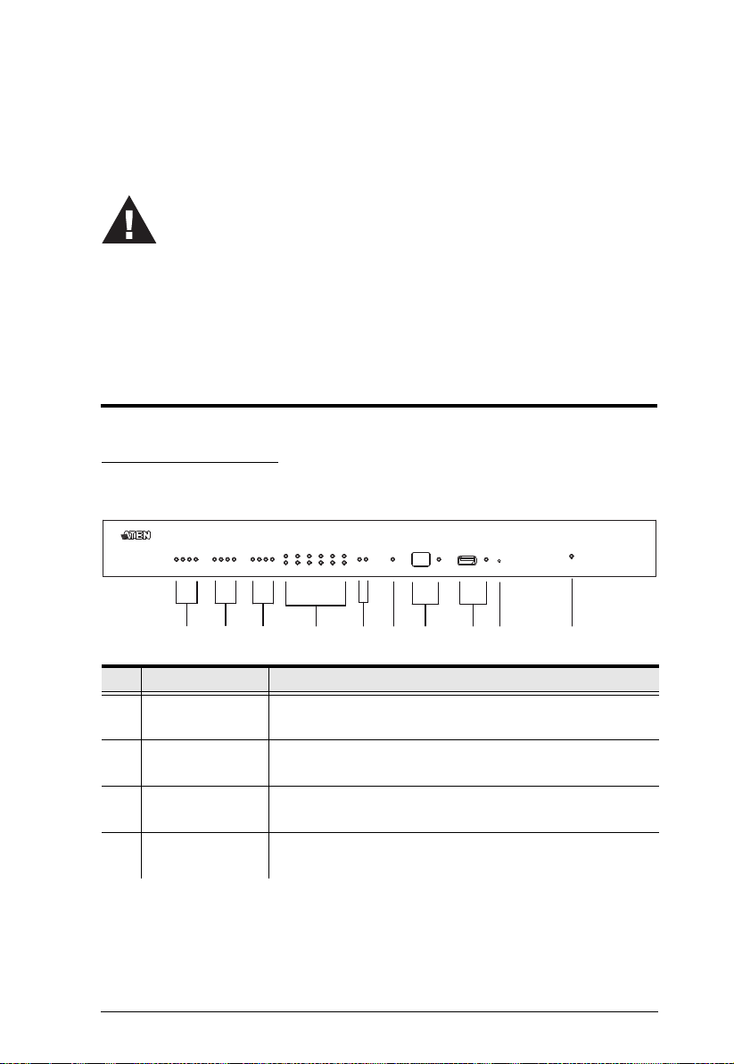
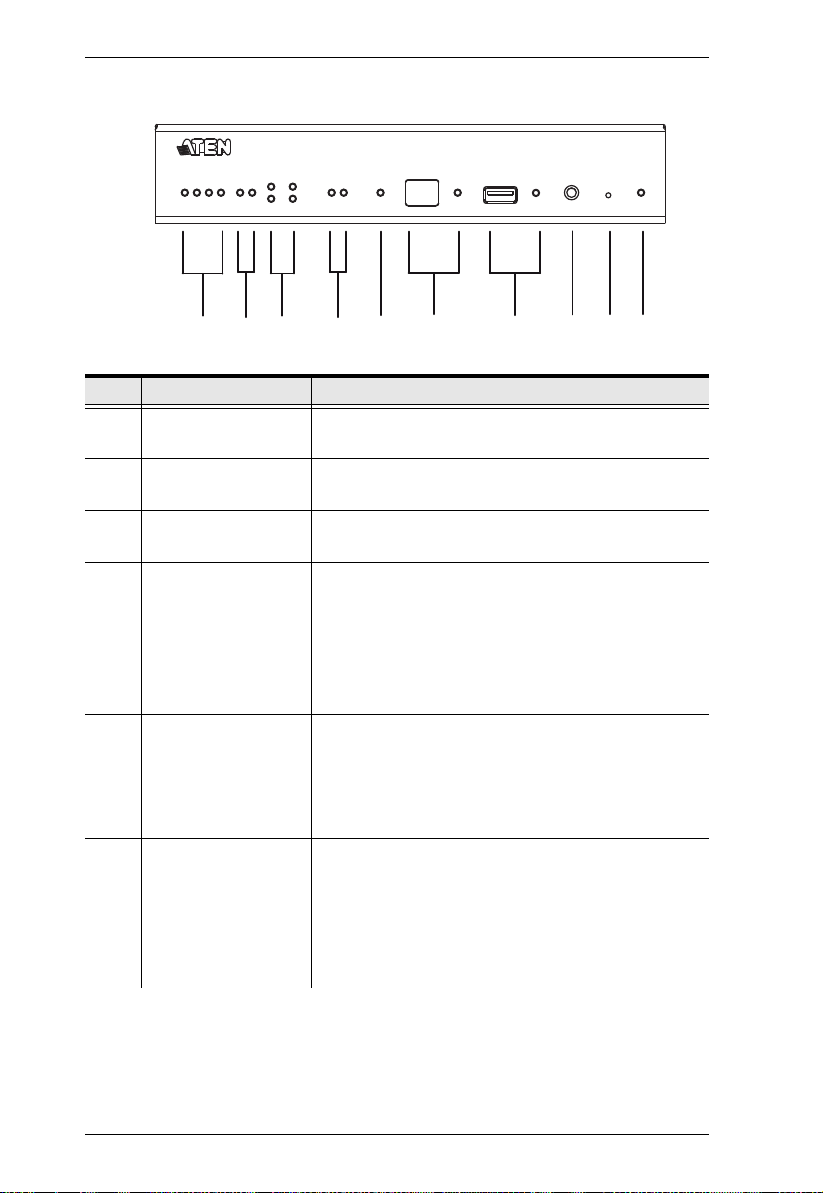
VK2100 Front View
Chapter 2
Hardware Setup
2
1
No. Component Description
1 Relay LED The LED lights green to indicate an active device connection
2 IR/Serial LED The LED lights green to indicate an active device connection
3 I/O LED The LED lights green to indicate an active device connection
4 Serial LED The LED (1~6) lights green to indicate serial signals are
4
3
(closed loop).
and IR/Serial signals are being transmitted.
and I/O signals are being transmitted.
being transmitted.
5
6
8
7
9
10
11

ATEN Control System User Manual
No. Component Description
5 Ethernet LED The LEDs provide information about the network
connection:
Link: The LED blinks green to indicate Ethernet signals
are being transmitted.
ACT: The LED lights green to indicate 100Mbps transmis-
sions.
6 DC Overload LED The LED lights orange to indicate DC output exceeds
maximum output.
Note: When the LED lights orange, please unplug any of the
connected devices to keep its total output under 24W.
7 IR Receiver / LED This IR receiver passes the functions of a remote control to
the VK2100 in learning mode. The distance between the IR
remote and the receiver window should be kept under 10cm
with a direct line of sight.
The LED blinks green to indicate the unit is ready to
receive signals from an IR remote control.
8 USB Port / LED This is where a USB device plugs in to upload Viewer files to
the VK2100.
The LED blinks green to indicate Viewer files are being
uploaded, and lights green to indicate a successful upload
of Viewer files.
The LED lights orange to indicate Viewer files failed to
upload.
9 Reset This semi-recessed pushbutton can be pressed to reset the
VK2100’s network settings.
10 Power LED Lights green when the unit is turned on.
12
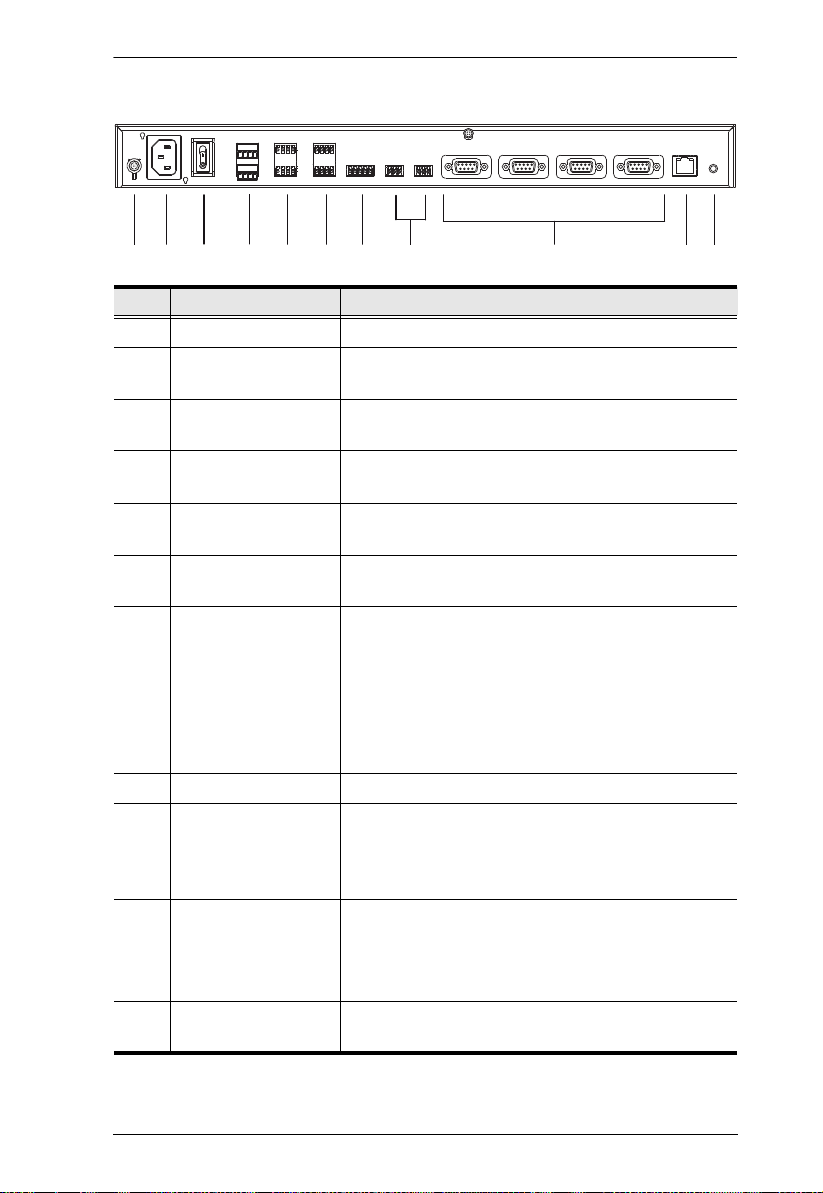
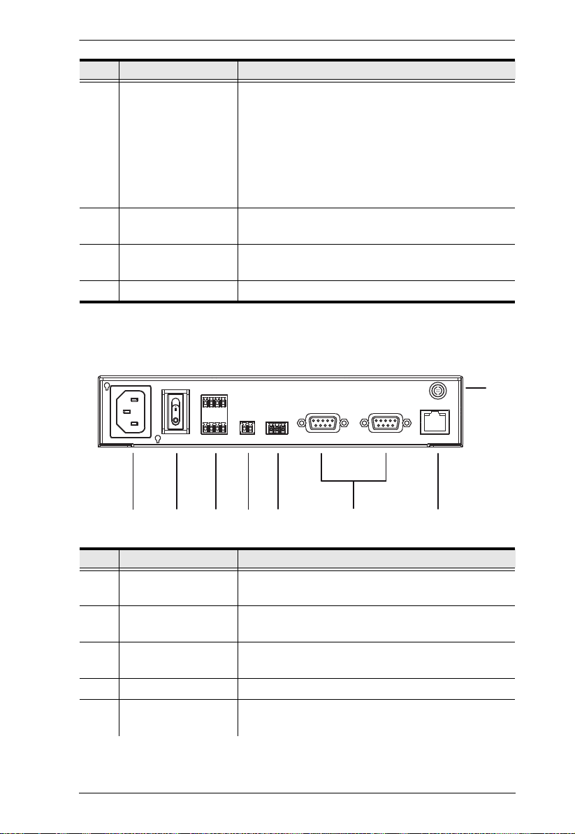
VK2100 Rear View
Chapter 2. Hardware Setup
2 3
1
4
5 687
9
10
No. Component Description
1 Grounding Terminal The grounding wire attaches here.
2 Power Socket This is a standard 3-pin AC power socket. The power
cord from an AC source plugs in here.
3 Power Switch This is a standard rocker switch that powers the unit
on and off.
4 DC Output Ports Four outputs provide a total power output of 24W /2A
max.
5 Relay Channels Four channels; normally open, isolated relays with a
contact rating of 24VDC, 2A max.
6 IR / Serial Ports Four IR ports that can also be configured as RS-232
TX ports. pin1: Signal / pin2: Ground.
7 I/O Channels Four channels that can be configured as digital input
or digital output ports.
Digital Input: 0-24VDC programmable input range or
contact closure with +12VDC pull-up
Digital Output: 250mA sink from 12VDC
Pin1~4: Signal / Pin5: Ground
8 RS-232 Serial Ports Two RS-232 ports with TX/RX functions supported.
9 RS-232/422/485
Serial Ports
10 Ethernet Port This RJ-45 port is used for the network connection. If
11 Controller ID Switch This 16-segment switch is used for controller ID
Four ports with supported RS-232/422/485 conversion
by pin assignment and RTS/CTS flow control. The
RS232, RS422, or RS485 connection is defined by
pin. For pin assignments, see page 32.
no IP address is assigned within 30 seconds, the
default IP settings will be used:
IP: 192.168.0.60 / mask: 255.255.255.0
selection.
11
13
ATEN Control System User Manual
1
2
3
56 7 8
4
9 10
VK1100 Front View
No. Component Description
1 Relay LED The LED lights green to indicate an active device
connection (closed loop).
2 IR/Serial LED The LED lights green to indicate an active device
connection and IR/Serial signals are being transmitted.
3 Serial LED The LED (1~2) lights green to indicate serial signals
are being transmitted.
4 Ethernet Link / ACT
LED
The LEDs provide information about the network
connection:
Link: The LED blinks green to indicate Ethernet sig-
nals are being transmitted.
ACT: The LED lights green to indicate 100Mbps
transmissions.
5 DC Output Overload
LED
6 IR Receiver / LED This IR receiver passes the functions of a remote
The LED lights orange to indicate DC output exceeds
maximum output.
Note: When the LED lights orange, please unplug any
of the connected devices to keep its total output under
12W.
control to the VK1100 in learning mode. The distance
between the IR remote and the receiver window
should be kept under 10cm with a direct line of sight.
The LED blinks green to indicate the unit is ready to
receive signals from an IR remote control.
14
Chapter 2. Hardware Setup
1 2 3 4 5 76
8
No. Component Description
7 USB Port / LED This is where a USB device plugs in to upload Viewer
files to the VK1100.
The LED blinks green to indicate Viewer files are
being uploaded, and lights green to indicate a
successful upload of Viewer files.
The LED lights orange to indicate Viewer files failed
to upload.
8 Controller ID Switch This 16-segment switch is used for controller ID
selection.
9 Reset This semi-recessed pushbutton can be pressed to
reset the VK1100’s network settings.
10 Power LED Lights green when the unit is turned on.
VK1100 Rear View
No. Component Description
1 Power Socket This is a standard 3-pin AC power socket. The power
cord from an AC source plugs in here.
2 Power Switch This is a standard rocker switch that powers the unit
on and off.
3 Relay Channels Four channels; normally open, isolated relays with a
contact rating of 24VDC, 2A max.
4 DC Output Ports One output provides a total power output of 12W max.
5 IR / Serial Ports Two IR ports that can also be configured as RS-232
TX ports. pin1: Signal / pin2: Ground.
15
ATEN Control System User Manual
No. Component Description
6 RS-232/422/485
Serial Ports
7 Ethernet Port This RJ-45 port is used for the network connection. If
8 Grounding Terminal The grounding wire attaches here.
Two ports with supported RS-232/422/485 conversion
by pin assignment and RTS/CTS flow control. The
RS232, RS422, or RS485 connection is defined by
pin. For pin assignments, see page 32.
no IP address is assigned within 30 seconds, the
default IP settings will be used:
IP: 192.168.0.60 / mask: 255.255.255.0
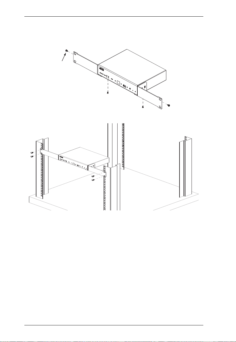
Rack Mounting the ATEN Control Box
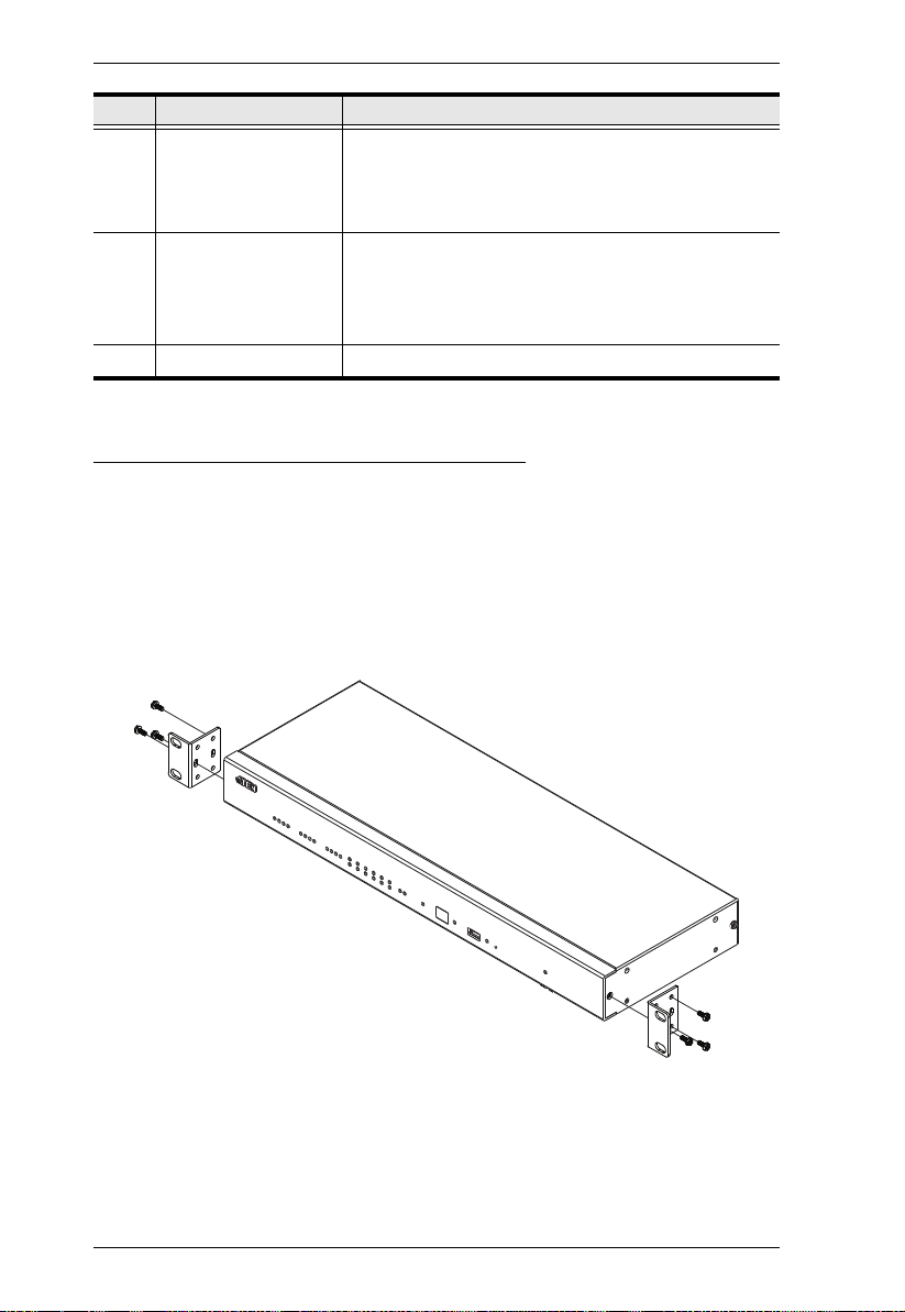
VK2100
The VK2100 can be mounted in a 19” (1U) system rack. To install the device
in a rack, do the following:
1. Use the M3 x 8 Phillips head hex screws supplied with the Rack Mount
Kit to screw the rack mounting brackets onto the front of the unit.
2. Position the unit in the front of the rack and align the holes in the mounting
brackets with the holes in the rack.
16
3. Screw the mounting brackets to the rack.
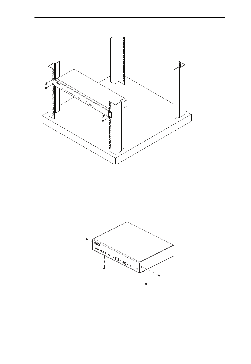
VK1100
Chapter 2. Hardware Setup
Optionally purchase an ATEN Rack Mount Kit to install VK1100 in a 19” (1U)
system rack. To install the device in a rack, do the following:
1. Remove the side and bottom screws from the front of the VK1000.
17
ATEN Control System User Manual
M3X6
Hexagon
Screw
2. Use the two bottom screws removed in step 1 to secure the bottom of the
brackets, and two M3X6 hexagon screws (from the rack mount kit) to
secure the side of the bracket to the VK1100.
3. Screw the mounting brackets to the rack.
18
 Loading...