

Aten VE8900, VE8950 Users guide
HDMI over IP Video Extender
VE8900 / VE8950 User Manual
www.aten.com

VE8900 / VE8950 User Manual
EMC Information
FEDERAL COMMUNICATIONS COMMISSION INTERFERENCE
STATEMENT: This equipment has been tested and found to comply with the
limits for a Class A digital device, pursuant to Part 15 of the FCC Rules. These
limits are designed to provide reasonable protection against harmful
interference when the equipment is operated in a commercial environment.
This equipment generates, uses, and can radiate radio frequency energy and, if
not installed and used in accordance with the instruction manual, may cause
harmful interference to radio communications. Operation of this equipment in
a residential area is likely to cause harmful interference in which case the user
will be required to correct the interference at his own expense.
FCC Caution: Any changes or modifications not expressly approved by the
party responsible for compliance could void the user's authority to operate this
equipment.
Warning: Operation of this equipment in a residential environment could cause
radio interference.
Suggestion: Shielded twisted pair (STP) cables must be used with the unit to
ensure compliance with FCC & CE standards.
This device complies with Part 15 of the FCC Rules. Operation is subject to the
following two conditions: (1) this device may not cause harmful interference,
and (2) this device must accept any interference received, including
interference that may cause undesired operation.
RoHS
This product is RoHS compliant.
ii

VE8900 / VE8950 User Manual
About This Manual
This User Manual is provided to help you get the most from your VE8900 /
VE8950 device and the ATEN VE Manager. It covers all aspects of
installation, configuration, and operation. An overview of the information
found in the manual is provided below.
Chapter 1, Introduction and Getting Started, introduces you to the
features and purposes of VE8900 / VE8950 HDMI over IP Video Extenders.
Chapter 2, Hardware Setup, introduces you to panel components and
provides step-by-step instructions for installing and setting up your VE8900 /
VE8950 hardware.
Chapter 3, Panel Operation, provides LED indicator information and
functions of the panel pushbuttons.
Chapter 4, Management, provides an overview of the VE Manager’s main
screen and step-by-step instructions of creating and editing display layouts.
Chapter 5, System Settings, provides information on the general settings,
and how to back up, restore, and upgrade the VE8900 / VE8950 system
firmware.
Chapter 6, CLI Commands, provides information on required
configurations for establishing sessions via telnet, TCP, or RS-232 serial
signals, and list of supported CLI commands.
Chapter 7, Mobile Control App, provides information on installing,
configuring, and using the application.
Appendix, provides product safety instructions, technical support details, and
product specifications.
iii

VE8900 / VE8950 User Manual
Conventions
This manual uses the following conventions:
Monospaced Indicates text that you should key in.
[ ] Indicates keys you should press. For example, [Enter] means
to press the Enter key. If keys need to be chorded, they appear
together in the same bracket with a plus sign between them:
[Ctrl+Alt].
1. Numbered lists represent procedures with sequential steps.
♦ Bullet lists provide information, but do not involve sequential
steps.
→ Indicates selecting the option (on a menu or dialog box, for
example), that comes next. For example, Start
to open the Start menu, and then select Run.
Indicates critical information.
Product Information
→ Run means
For information about all ATEN products and how they can help you connect
without limits, visit ATEN on the Web or contact an ATEN Authorized
Reseller. Visit ATEN on the Web for a list of locations and telephone numbers:
International http://www.aten.com
North America http://www.aten-usa.com
iv

VE8900 / VE8950 User Manual
User Information
Online Registration
Be sure to register your product at our online support center:
International http://eservice.aten.com
Telephone Support
For telephone support, call this number:
International 886-2-8692-6959
China 86-400-810-0-810
Japan 81-3-5615-5811
Korea 82-2-467-6789
North America 1-888-999-ATEN ext 4988
1-949-428-1111
User Notice
All information, documentation, and specifications contained in this manual
are subject to change without prior notification by the manufacturer. The
manufacturer makes no representations or warranties, either expressed or
implied, with respect to the contents hereof and specifically disclaims any
warranties as to merchantability or fitness for any particular purpose. Any of
the manufacturer's software described in this manual is sold or licensed as is.
Should the programs prove defective following their purchase, the buyer (and
not the manufacturer, its distributor, or its dealer), assumes the entire cost of all
necessary servicing, repair and any incidental or consequential damages
resulting from any defect in the software.
The manufacturer of this system is not responsible for any radio and/or TV
interference caused by unauthorized modifications to this device. It is the
responsibility of the user to correct such interference.
The manufacturer is not responsible for any damage incurred in the operation
of this system if the correct operational voltage setting was not selected prior
to operation. PLEASE VERIFY THAT THE VOLTAGE SETTING IS
CORRECT BEFORE USE.
v

VE8900 / VE8950 User Manual
Package Contents
Check to make sure that all of the components are present and in good order.
If anything is missing or was damaged in shipping, contact your dealer.
VE8900T
1 VE8900 HDMI over IP Transmitter
1 RS-232 Terminal Block
1 5V Power Adapter
1 User Instructions
VE8900R
1 VE8900 HDMI over IP Receiver
1 RS-232 Terminal Block
1 5V Power Adapter
1 User Instructions
VE8950T
1 VE8950 4K HDMI over IP Transmitter
1 RS-232 Terminal Block
1 5V Power Adapter
1 User Instructions
VE8950R
1 VE8950 4K HDMI over IP Receiver
1 RS-232 Terminal Block
1 5V Power Adapter
1 User Instructions
vi

VE8900 / VE8950 User Manual
Read this manual thoroughly and follow the installation and operation
procedures carefully to prevent any damage to the device or to any other
connected devices.
Note: The VE8900 / VE8950 product firmware may have been updated with
new features after the release of this manual. For an up-to-date VE8900
/ VE8950 user manual, visit http://www.aten.com/global/en/
vii

VE8900 / VE8950 User Manual
Contents
EMC Information. . . . . . . . . . . . . . . . . . . . . . . . . . . . . . . . . . . . . . . . . . . . . ii
About This Manual . . . . . . . . . . . . . . . . . . . . . . . . . . . . . . . . . . . . . . . . . . .iii
Conventions . . . . . . . . . . . . . . . . . . . . . . . . . . . . . . . . . . . . . . . . . . . . . . . .iv
Product Information . . . . . . . . . . . . . . . . . . . . . . . . . . . . . . . . . . . . . . . . . .iv
User Information . . . . . . . . . . . . . . . . . . . . . . . . . . . . . . . . . . . . . . . . . . . . v
Package Contents . . . . . . . . . . . . . . . . . . . . . . . . . . . . . . . . . . . . . . . . . . .vi
Contents . . . . . . . . . . . . . . . . . . . . . . . . . . . . . . . . . . . . . . . . . . . . . . . . . viii
1. Introduction and Getting Started
Overview. . . . . . . . . . . . . . . . . . . . . . . . . . . . . . . . . . . . . . . . . . . . . . . . . . . 1
Features and Benefits. . . . . . . . . . . . . . . . . . . . . . . . . . . . . . . . . . . . . . . . . 2
Getting Started Tasks. . . . . . . . . . . . . . . . . . . . . . . . . . . . . . . . . . . . . . . . . 6
2. Hardware Setup
Components . . . . . . . . . . . . . . . . . . . . . . . . . . . . . . . . . . . . . . . . . . . . . . . . 7
VE8900T / VE8950T Rear View . . . . . . . . . . . . . . . . . . . . . . . . . . . . . . 8
VE8900R / VE8950R Front View . . . . . . . . . . . . . . . . . . . . . . . . . . . . . 8
Mounting the VE8900 / VE8950 Device . . . . . . . . . . . . . . . . . . . . . . . . . . 10
Wall Mount . . . . . . . . . . . . . . . . . . . . . . . . . . . . . . . . . . . . . . . . . . . . . 10
Rack Mount . . . . . . . . . . . . . . . . . . . . . . . . . . . . . . . . . . . . . . . . . . . . . 10
Connecting VE8900 / VE8950 . . . . . . . . . . . . . . . . . . . . . . . . . . . . . . . . . 11
3. Panel Operation
Overview. . . . . . . . . . . . . . . . . . . . . . . . . . . . . . . . . . . . . . . . . . . . . . . . . . 15
Status LEDs . . . . . . . . . . . . . . . . . . . . . . . . . . . . . . . . . . . . . . . . . . . . . . . 15
Panel Controls . . . . . . . . . . . . . . . . . . . . . . . . . . . . . . . . . . . . . . . . . . . . . 16
Assigning Sources Using the Device Panel . . . . . . . . . . . . . . . . . . . . . . . 18
4. Management
Overview. . . . . . . . . . . . . . . . . . . . . . . . . . . . . . . . . . . . . . . . . . . . . . . . . . 19
Looking Up the Login IP Address . . . . . . . . . . . . . . . . . . . . . . . . . . . . . . . 20
Find My VE Extension . . . . . . . . . . . . . . . . . . . . . . . . . . . . . . . . . . . . . . . 21
Start VE Manager using Find My VE Extension . . . . . . . . . . . . . . . . . 23
Logging In and Configuring VE Manager . . . . . . . . . . . . . . . . . . . . . . . . . 25
The Main Screen . . . . . . . . . . . . . . . . . . . . . . . . . . . . . . . . . . . . . . . . . . . 28
Apply / Auto Apply. . . . . . . . . . . . . . . . . . . . . . . . . . . . . . . . . . . . . . . . 29
Assigning Sources Using VE Manager . . . . . . . . . . . . . . . . . . . . . . . . . . 30
Configuring and Setting Up a Video Wall . . . . . . . . . . . . . . . . . . . . . . . . . 33
Creating a Video Wall Layout . . . . . . . . . . . . . . . . . . . . . . . . . . . . . . . 34
Editing a Video Wall Layout . . . . . . . . . . . . . . . . . . . . . . . . . . . . . . . . 36
Editing a Preview . . . . . . . . . . . . . . . . . . . . . . . . . . . . . . . . . . . . . . . . 37
Profile . . . . . . . . . . . . . . . . . . . . . . . . . . . . . . . . . . . . . . . . . . . . . . . . . . . . 38
viii

VE8900 / VE8950 User Manual
Creating a Profile. . . . . . . . . . . . . . . . . . . . . . . . . . . . . . . . . . . . . . . . .38
Edit, Delete and Disconnect Profile. . . . . . . . . . . . . . . . . . . . . . . . . . . 40
Edit. . . . . . . . . . . . . . . . . . . . . . . . . . . . . . . . . . . . . . . . . . . . . . . . .40
Delete . . . . . . . . . . . . . . . . . . . . . . . . . . . . . . . . . . . . . . . . . . . . . .41
Disconnect . . . . . . . . . . . . . . . . . . . . . . . . . . . . . . . . . . . . . . . . . . . 41
Select / Apply Profile . . . . . . . . . . . . . . . . . . . . . . . . . . . . . . . . . . . . . 42
Setup Profile Schedules . . . . . . . . . . . . . . . . . . . . . . . . . . . . . . . . . . . 43
Managing VE8900 / VE8950 Devices . . . . . . . . . . . . . . . . . . . . . . . . . . . 46
Checking VE8900 / VE8950 Statuses. . . . . . . . . . . . . . . . . . . . . . . . . 46
5. System Settings
Overview . . . . . . . . . . . . . . . . . . . . . . . . . . . . . . . . . . . . . . . . . . . . . . . . . .47
General Settings . . . . . . . . . . . . . . . . . . . . . . . . . . . . . . . . . . . . . . . . . . . .47
Transmitter Settings . . . . . . . . . . . . . . . . . . . . . . . . . . . . . . . . . . . . . . . . . 49
Receiver Settings . . . . . . . . . . . . . . . . . . . . . . . . . . . . . . . . . . . . . . . . . . . 51
Batch Configuration . . . . . . . . . . . . . . . . . . . . . . . . . . . . . . . . . . . . . . . . . 53
Maintenance . . . . . . . . . . . . . . . . . . . . . . . . . . . . . . . . . . . . . . . . . . . . . . .55
Upgrading VE8900 / VE8950 Device Firmware . . . . . . . . . . . . . . . . .55
Synchronizing All Devices . . . . . . . . . . . . . . . . . . . . . . . . . . . . . . . . . .56
Backing Up VE8900 / VE8950 Device Settings . . . . . . . . . . . . . . . . . 56
Restoring VE8900 / VE8950 Device Settings . . . . . . . . . . . . . . . . . . 57
Account Settings . . . . . . . . . . . . . . . . . . . . . . . . . . . . . . . . . . . . . . . . . . . 58
6. CLI Commands
Overview . . . . . . . . . . . . . . . . . . . . . . . . . . . . . . . . . . . . . . . . . . . . . . . . . .59
Before You Start . . . . . . . . . . . . . . . . . . . . . . . . . . . . . . . . . . . . . . . . . . . .59
Executing Commands . . . . . . . . . . . . . . . . . . . . . . . . . . . . . . . . . . . . . . .60
Commands . . . . . . . . . . . . . . . . . . . . . . . . . . . . . . . . . . . . . . . . . . . . . . . . 62
Guidelines . . . . . . . . . . . . . . . . . . . . . . . . . . . . . . . . . . . . . . . . . . . . . .62
Switching Sources . . . . . . . . . . . . . . . . . . . . . . . . . . . . . . . . . . . . . . .63
Examples . . . . . . . . . . . . . . . . . . . . . . . . . . . . . . . . . . . . . . . . . . . .63
Switching Video, USB, RS-232, and/or IR Paths . . . . . . . . . . . . . . . . 64
Examples . . . . . . . . . . . . . . . . . . . . . . . . . . . . . . . . . . . . . . . . . . . .64
Disabling Video, USB, RS-232, and/or IR Paths . . . . . . . . . . . . . . . . 65
Example. . . . . . . . . . . . . . . . . . . . . . . . . . . . . . . . . . . . . . . . . . . . .65
Displaying Port-Switching Alerts . . . . . . . . . . . . . . . . . . . . . . . . . . . .66
Looking Up System Settings . . . . . . . . . . . . . . . . . . . . . . . . . . . . . . .67
Configuring Video Wall Settings . . . . . . . . . . . . . . . . . . . . . . . . . . . . .68
Examples . . . . . . . . . . . . . . . . . . . . . . . . . . . . . . . . . . . . . . . . . . . .68
Muting VE8900 / VE8950 Receivers or Video Walls . . . . . . . . . . . . .69
Examples . . . . . . . . . . . . . . . . . . . . . . . . . . . . . . . . . . . . . . . . . . . .69
Disabling a Video Output . . . . . . . . . . . . . . . . . . . . . . . . . . . . . . . . . .70
Enabling/Disabling the OSD Display of a Receiver . . . . . . . . . . . . . .71
Configuring the EDID Mode . . . . . . . . . . . . . . . . . . . . . . . . . . . . . . . . 72
Rebooting the VE8900 / VE8950 . . . . . . . . . . . . . . . . . . . . . . . . . . . .73
Examples . . . . . . . . . . . . . . . . . . . . . . . . . . . . . . . . . . . . . . . . . . . .73
ix

VE8900 / VE8950 User Manual
Setting the Baud Rate . . . . . . . . . . . . . . . . . . . . . . . . . . . . . . . . . . . . 74
Examples. . . . . . . . . . . . . . . . . . . . . . . . . . . . . . . . . . . . . . . . . . . . 74
Displaying Device Status . . . . . . . . . . . . . . . . . . . . . . . . . . . . . . . . . . 75
Examples. . . . . . . . . . . . . . . . . . . . . . . . . . . . . . . . . . . . . . . . . . . . 75
7. Mobile Control App
Overview. . . . . . . . . . . . . . . . . . . . . . . . . . . . . . . . . . . . . . . . . . . . . . . . . . 77
Requirements . . . . . . . . . . . . . . . . . . . . . . . . . . . . . . . . . . . . . . . . . . . 77
Main Page . . . . . . . . . . . . . . . . . . . . . . . . . . . . . . . . . . . . . . . . . . . . . 78
Live Views. . . . . . . . . . . . . . . . . . . . . . . . . . . . . . . . . . . . . . . . . . . . . . 79
Switching a Source . . . . . . . . . . . . . . . . . . . . . . . . . . . . . . . . . . . . . . . 79
Switching Multiple Sources and Displays . . . . . . . . . . . . . . . . . . . . . . 81
Changing the Operation Mode of a Video Wall/Display . . . . . . . . . . . 84
Applying a Display Profile . . . . . . . . . . . . . . . . . . . . . . . . . . . . . . . . . . 85
Configuring the Profile Schedule . . . . . . . . . . . . . . . . . . . . . . . . . . . . 86
System Settings and Status . . . . . . . . . . . . . . . . . . . . . . . . . . . . . . . . 88
Appendix
Safety Instructions . . . . . . . . . . . . . . . . . . . . . . . . . . . . . . . . . . . . . . . . . . 89
General . . . . . . . . . . . . . . . . . . . . . . . . . . . . . . . . . . . . . . . . . . . . . . . . 89
Rack Mounting . . . . . . . . . . . . . . . . . . . . . . . . . . . . . . . . . . . . . . . . . . 91
Technical Support . . . . . . . . . . . . . . . . . . . . . . . . . . . . . . . . . . . . . . . . . . 92
Specifications . . . . . . . . . . . . . . . . . . . . . . . . . . . . . . . . . . . . . . . . . . . . . . 93
Supported Browsers . . . . . . . . . . . . . . . . . . . . . . . . . . . . . . . . . . . . . . . . 95
Limited Warranty. . . . . . . . . . . . . . . . . . . . . . . . . . . . . . . . . . . . . . . . . . . . 96
x

Chapter 1
Introduction and Getting Started
Overview
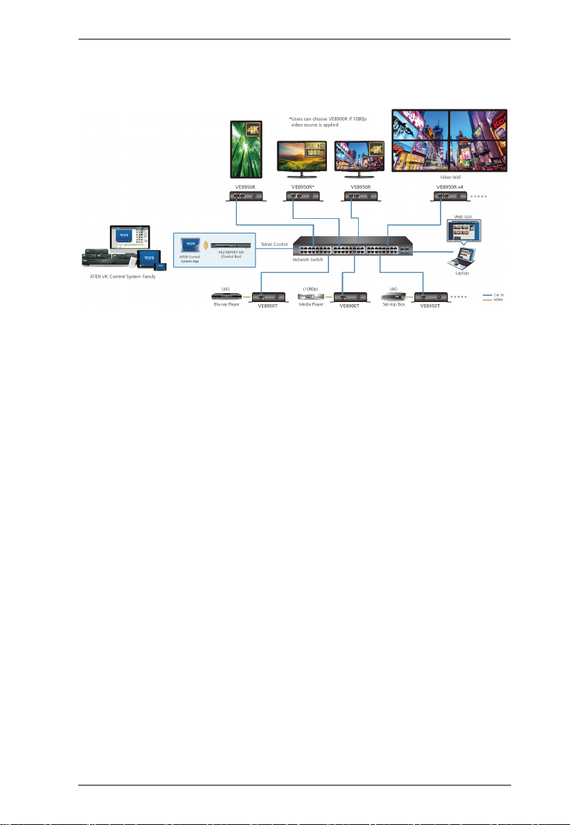
The ATEN VE8900 / VE8950 Video over IP Extenders deliver visually
lossless 1080p / 4K AV signals with low latency over long distance via a
standard Gigabit network switch.
The VE8900 / VE8950 provides an effective, easy-to-use, and economical
digital signage solution with the following features and advantages that
directly address the challenges system integrators encounter when
implementing AV over IP systems:
Limitless scalability and flexibility
No complicated IP setup
No additional server PCs or software required
Go further for less with daisy chaining
Engineered to meet today’s demands of large scale, multi-display, 1080p/4K
signal transmission, and designed to be easy to set up and operate, the
VE8900 / VE8950 Video over IP Extender is an ideal product for a wide range
of environments, such as trade shows, airports, university campuses,
conference centers, and shopping centers.
1

VE8900 / VE8950 User Manual
Features and Benefits
Light weight Compression with Ultra-low Latency
Delivers visually lossless high-quality video up to 1080p @ 60 Hz
(VE8900) / 4K @ 30 Hz 4:4:4 (VE8950)
Ensures stunning quality video using ATEN advanced video lossless
compression technology
EDID Expert™ selects the optimum EDID settings for smooth power-up,
high-quality display and the best video resolution across different screens
Offers different levels of video compression rate including Smooth,
Balance, and High Quality for users to choose depending on practical
usage
Limitless Scalability and Flexibility
Extends AV connections from a simple point-to-point to a multi-point to
multi-point setup via LAN without distance limitations
Offers multi-functionality in extender, splitter, matrix switch, video wall
and daisy chain applications
Mix and match the latest 4K displays and 1080p screens. The built-in
scaler automatically scales up incoming video signal to match the
maximum resolution of the connected display devices
Collaboration with ATEN Control System
Integrated solution – Compatible with ATEN Control System, allowing
users to directly operate VE8900/8950 via CLI Telnet or RS-232 protocol
2
Chapter 1. Introduction and Getting Started
Effortless operation – One click to effectively operate VE Manager, TV,
projector, source player, and related equipments via touch panel and
keypad
Spontaneous Scheduling Management
Offers an user-friendly scheduling management function for users to pre-
plan the display schedule
Provides robust and intuitive scheduling management options to help users
to manage all events in the calendar to as detailed as to setting events to
minute intervals
Integrates all VE89 units to arrange the profile by grouping individual
receiver or video wall
Multiple profiles can be arranged to play in any order over a selected
period of time
No Complicated IP Setup
Simple configuration that requires no extensive IT experience or extra
learning
Effortlessly switches among input sources via top panel pushbuttons
Web GUI-Based Management, No Additional Server PCs or Software
Required
Simple Access – Without typing IP address on Chrome browser, users are
allowed to directly link to VE Manager via one click on “Find My VE”
Chrome based free tool
3
VE8900 / VE8950 User Manual
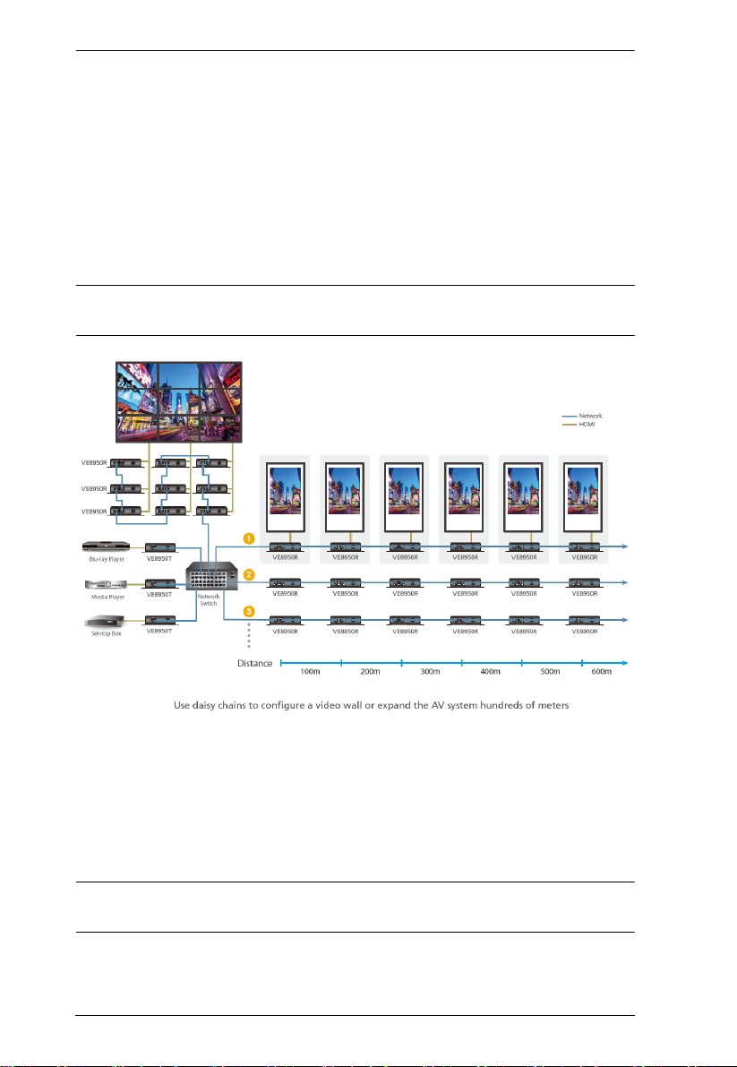
Go Further For Less with Daisy Chaining
Connects multiple displays through a single port to utilize every port of the
network switch and maximize their value
Easily expandable – cabling and system deployment is easy with no huge
network switches and fewer cables needed
Perfect for large-scale deployment covering hundreds of meters, such as
hotel facilities, airports, university campuses, stations, shopping malls, and
exhibition centers
Note: Depending on your network architecture, we recommend daisy
chaining up to 30 units. Please contact ATEN representatives for more details.
Video Wall Support
Supports up to 8 x 8 video wall (64 displays)
Supports horizontal or vertical (90° and 270° rotation) display orientation
Easily switches layout profiles, preview and drag-and-drop video sources
via the intuitive web GUI
Note: If you experience issues related to your network architecture, please
contact ATEN representatives for support.
4

Chapter 1. Introduction and Getting Started
Embedded / De-embedded Audio Support
For VE8900T / VE8950T – separate audio signal can be embedded into
the HDMI stream
For VE8900R / VE8950R – audio stream can be extracted from the HDMI
stream and delivered as a separate audio signal
Multiple Control Channels
Multiple control methods – the system can be managed via Ethernet or
top-panel pushbuttons
USB Connectivity – USB port (USB 2.0) allows for connection of devices
such as keyboard, mouse, flash drive, printer, and other USB peripherals*
Bi-directional IR Channel – IR transmission is processed one way at a
time
RS-232 Channel – bi-directional RS-232 serial port allows for connection
of peripherals such as touch screens and bar code scanners
Note: Each VE8900/8950 transmitter can be controlled by a total of 4 USB
touch screens installed to VE8900/8950 receivers.
5

VE8900 / VE8950 User Manual
Getting Started Tasks
Follow the steps below to install, connect, configure, and getting started with
your VE8900 / VE8950 devices.
1. Decide your network architecture and configuration. For more
information, see the Implementation Guide.
2. Mount your VE8900 / VE8950 devices on walls or racks. For more
information, see Mounting the VE8900 / VE8950 Device, page 10.
3. Connect the VE8900 / VE8950 devices to sources, displays, network, and
other hardware devices as required. For more information, see Connecting
VE8900 / VE8950, page 11.
4. Use one of the following methods to assign input sources.
Note: Skip this step if you have a point-to-point setup. In a point-to-point
setup, source input is automatically assigned.
Assign input sources using the device panel.
For more information, see Assigning Sources Using the Device Panel,
page 18.
Assign input sources using VE Manager.
For more information, see Logging In and Configuring VE Manager,
page 25 and Find My VE Extension, page 21.
6
Components
Before you proceed to hardware setup:
1. Please review the safety information regarding the placement of
this device in Safety Instructions, page 89.
2. Do not power on the VE8900 / VE8950 device until all the
necessary hardware is connected.
1
2
2
3
4
5
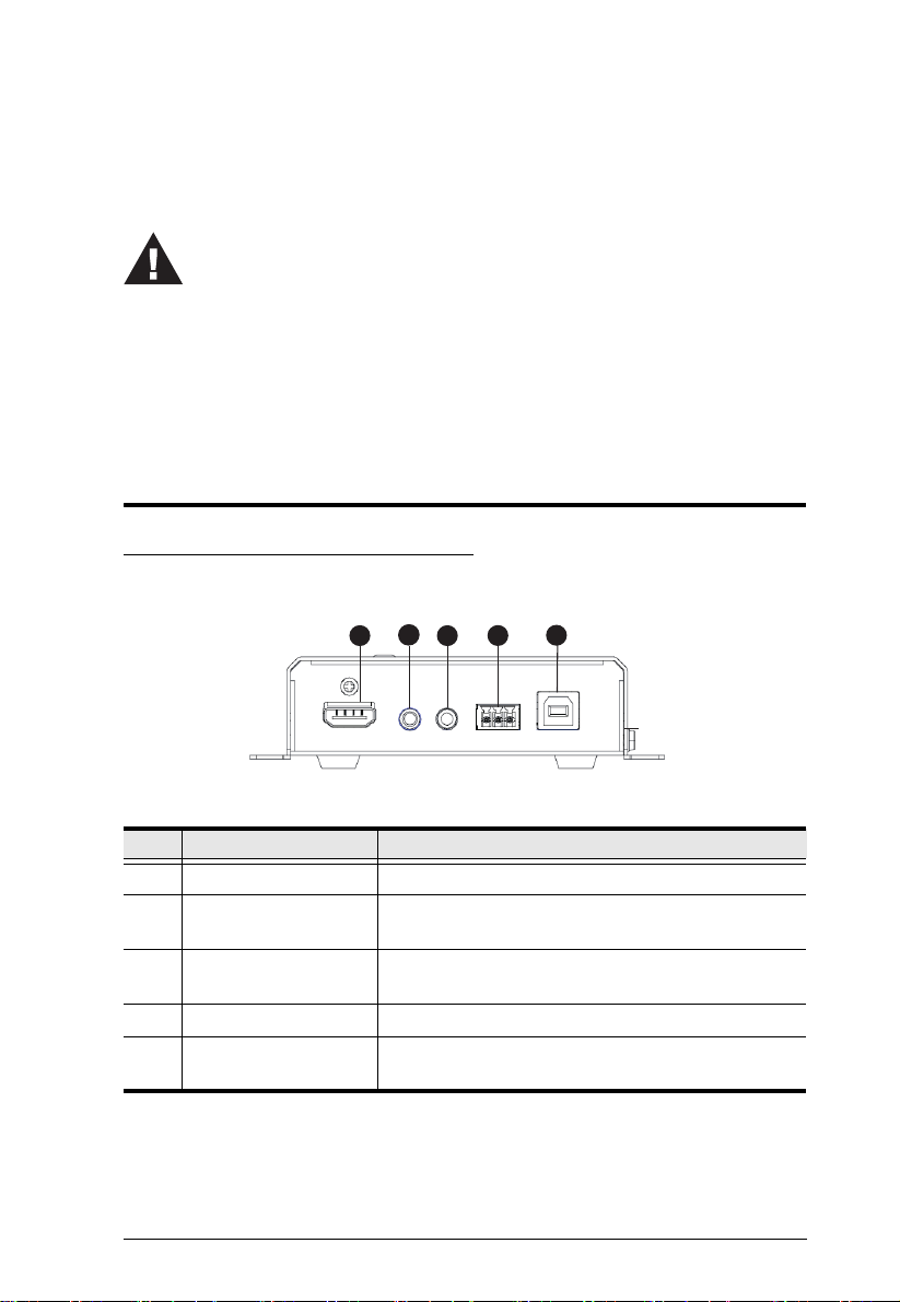
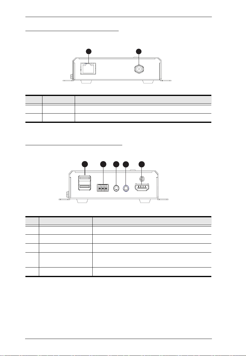
VE8900T / VE8950T Front View
Chapter 2
Hardware Setup
No. Component Function
1 HDMI In Connects an HDMI cable from the source device.
2 Audio Jack Connects to an analog audio player from the source
3 IR Port Connects to an IR receiver/transmitter to allow for
4 RS-232 Terminal Block Connects to a computer for serial control.
5 USB Type-B Connects to a virtual media or a USB peripheral
device. Note that microphones are not supported.
configuration using a remote control.
device.
7
VE8900 / VE8950 User Manual
1
2
1
2
3
4
5
VE8900T / VE8950T Rear View
No. Component Function
1 LAN Port Connects the unit to LAN with a network cable.
2 Power Jack Connects to the DC power adapter to provide power to the unit.
VE8900R / VE8950R Front View
No. Component Function
1 USB Type-A Connects to virtual media or a USB peripheral device.
2 RS-232 Terminal Block Connects to a serial device.
3 Audio Jack Connects to a speaker from the output device.
4 IR Port Connects to an IR receiver/transmitter to allow for
configuration using a remote control.
5 HDMI Out Connects to an HDMI cable from the output device.
8
Chapter 2. Hardware Setup
1
2
3
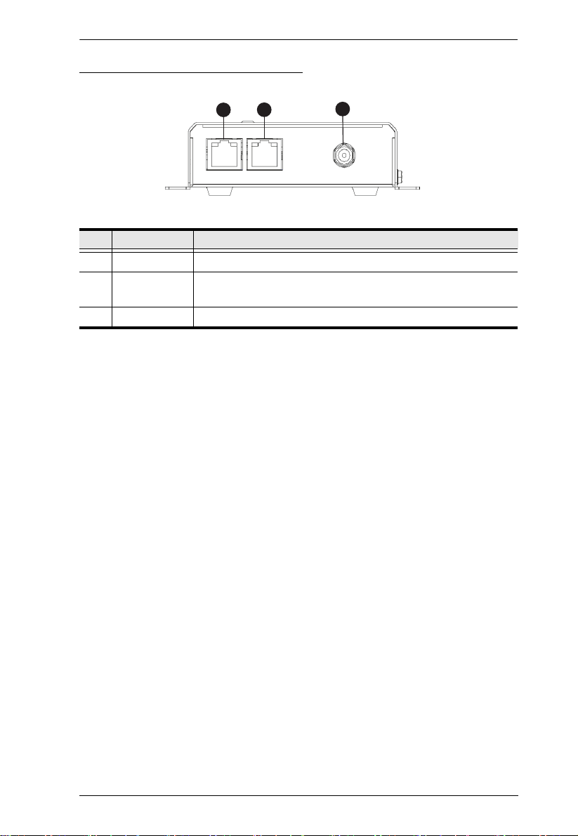
VE8900R / VE8950R Rear View
No. Component Function
1 LAN 1 Port Connects the unit to LAN with a network cable.
2 LAN 2 Port Connects to another VE8900R / VE8950R with a network cable
in a daisy-chain setup.
3 Power Jack Connects to the DC power adapter to provide power to the unit.
9
VE8900 / VE8950 User Manual
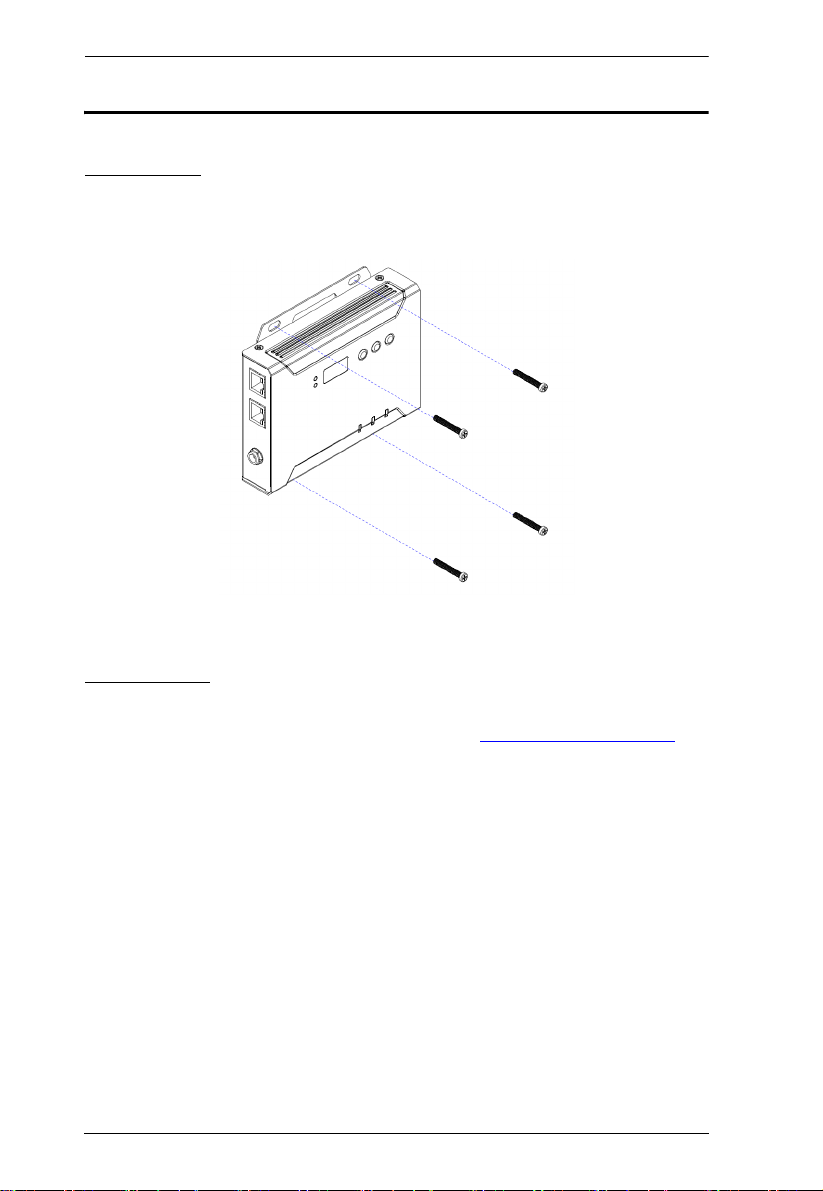
Mounting the VE8900 / VE8950 Device
Wall Mount
Secure or hang the VE8900 / VE8950 device to the wall using the built-in
brackets.
Rack Mount
Use the VE-RMK1U Rack Mount Kit to rack-mount the VE8900 / VE8950.
For more information about this accessory, go to www.aten.com/products
10
Chapter 2. Hardware Setup
Serial Device
Remote HDMI
Device
HDMI Source
Device
VE8900R
VE8900T
HDMI Display
RS-232 to
Serial Device
or
PC Control
by USB
IR Transmitter
Audio Speaker
7
HDMI
USB
Cat 5e
RS-232
Audio
IR
USB Peripherals
Audio Player
(Rear)
(Front)
(Rear)
(Front)
LAN
1
5
8
6
3
2
4
4
6
7
8
5
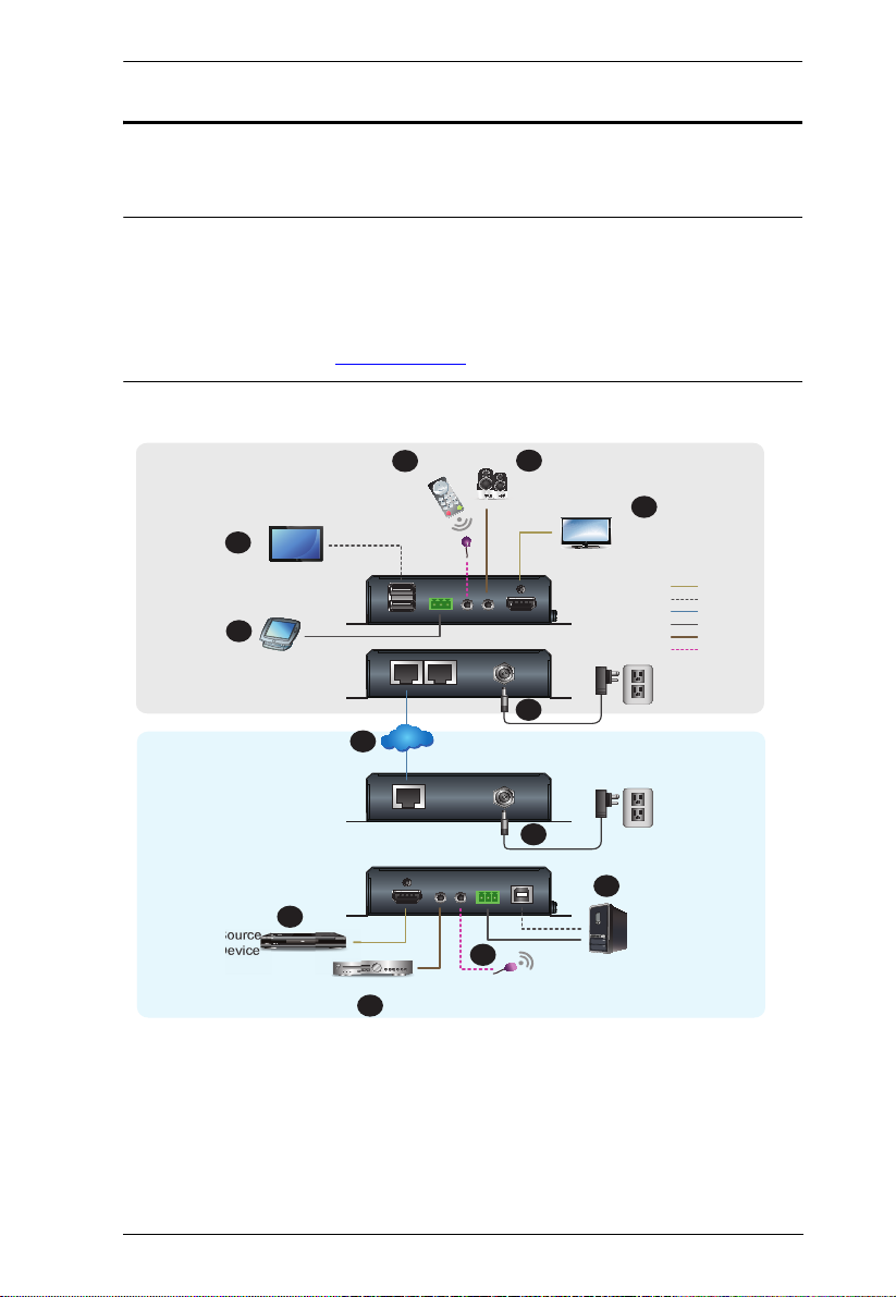
Connecting VE8900 / VE8950
Follow the steps below to connect your VE8900 / VE8950 devices with the
hardware as required.
Note:
For details on LED indicators to help you identify statuses of connection
or signal transmission, see Status LEDs, page 15.
For a list of compatible ATEN products, visit the VE8900 / VE8950
product web page at www.aten.com
11

VE8900 / VE8950 User Manual
1. Connect the HDMI In port on the VE8900T / VE8950T device to the
HDMI Out port on your video source device using an HDMI cable.
2. Connect the HDMI Out port on the VE8900R / VE8950R device to the
HDMI In port on your display device using an HDMI cable.
3. Depending on your deployment type, connect your VE8900T / VE8950T
and VE8900R / VE8950R to the same LAN.
Point-to-point deployment: directly connect the LAN 1 Ports of your
VE8900T / VE8950T and VE8900R / VE8950R with an RJ-45 cable.
Splitter and matrix deployment: connect the LAN 1 Ports of your
VE8900T / VE8950T and VE8900R / VE8950R to the same network
switch with RJ-45 cables.
4. Plug the Power Adapter into the Power Jack on the VE8900T / VE8950T
and VE8900R / VE8950R devices.
5. (Optional) Connect an RS-232 serial device or peripheral to the RS-232
Terminal Block on your VE8900R / VE8950R device. This device can be
a computer, a touch screen, a bar code scanner, or a control system.
[1]
6. (Optional) Connect an IR transmitter/receiver cable to the IR Ports of your
VE8900T / VE8950T and VE8900R / VE8950R devices.
[1]
7. (Optional) Connect USB peripherals to the USB ports on your VE8900T /
VE8950T and VE8900R / VE8950R devices.
[1] [2]
8. (Optional) Connect an audio device to the VE8900R / VE8950R Audio
[3]
Jack.
12
Chapter 2. Hardware Setup
Note:
1. The IR, RS-232, and USB signal transmissions are disabled by default. To
enable the functions, go to System Settings > Receiver > IR/RS232 or
USB in VE Manager and select the signal source.
2. Each VE8900 / VE8950 transmitter can be controlled by a total of 4 USB
touch screens installed to VE8900 / VE8950 receivers.
3. To receive HDMI audio on the VE8900 / VE8950 transmitter, make sure
to configure the following in VE Manager:
Set the transmitter to receive HDMI audio:
Go to System Settings > Transmitt er > Audio In in VE Manager and
change the setting to HDMI.
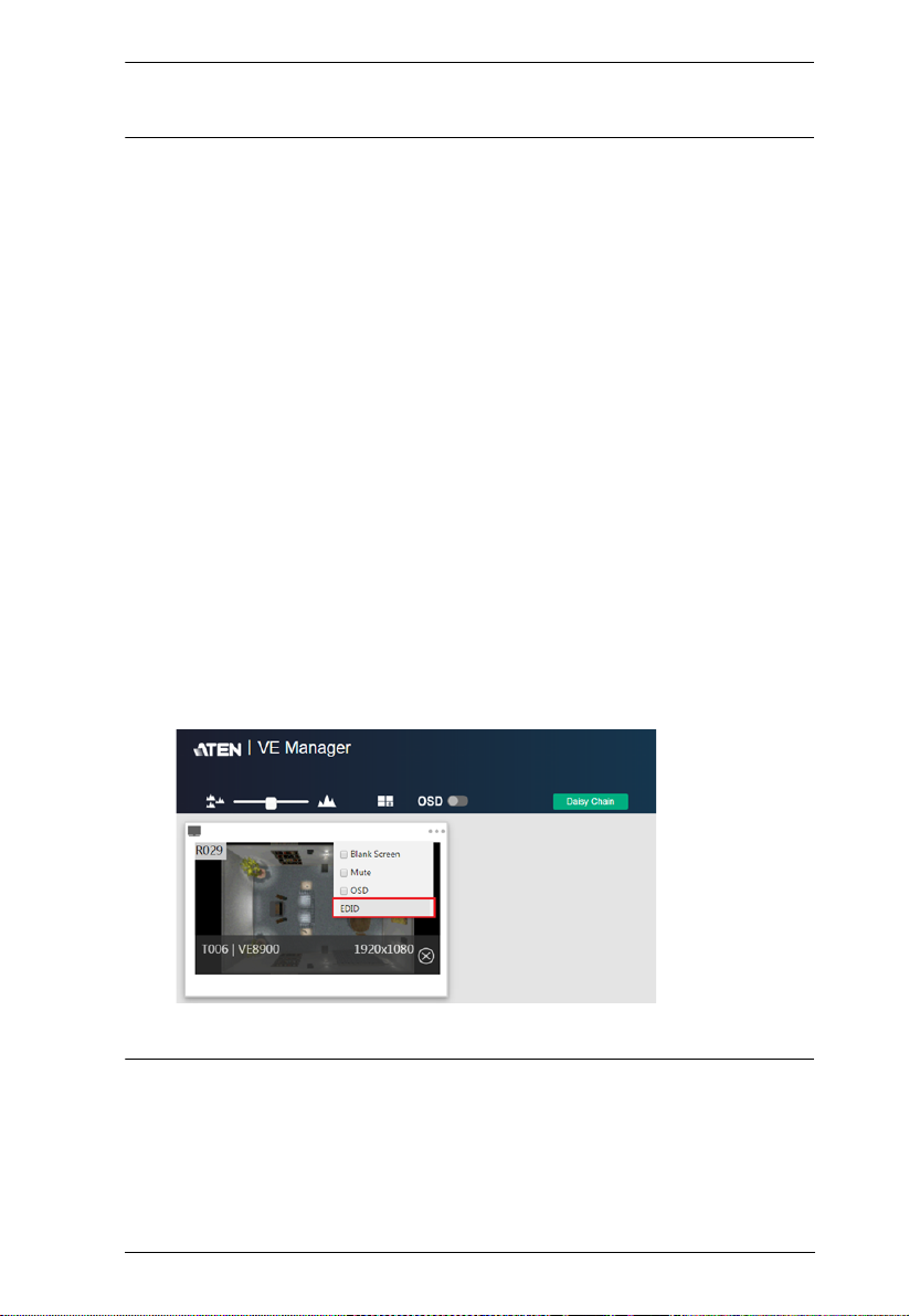
To allow for 5.1 or 7.1 surround sound on a VE8900 / VE8950
receiver, do the following:
a) In VE Manager, go to System Settings > Tra nsmitt er, access the
configuration window for the corresponding transmitter, and then set
EDID to Manual.
b) From the VE Manager’s preview area, click on the ... icon and select
EDID to allow transmission of the receiver’s EDID to the transmitter.
13

VE8900 / VE8950 User Manual
This Page Intentionally Left Blank
14

Chapter 3
Panel Operation
Overview
This chapter provides information on panel LEDs and instructions to operate
the VE8900 / VE8950 using the panel buttons.
Status LEDs
Both the VE8900 / VE8950 Transmitter and Receiver have front panel LEDs
to indicate their operating and power status.
LED Indication Description
Power Lights green The device is powered on.
Off Power is off.
LINK Lights orange LAN is connected.
Off LAN is not connected.
HDMI Out Lights orange The video output is stable.
Blinks orange The video output is unstable.
Off The video output is not transmitted.
RJ-45 Connector
(Left LED)
RJ-45 Connector
(Right LED)
Lights orange Data is being transmitted at 100Mpbs.
Lights green Data is being transmitted at 1Gpbs.
Lights green LAN is connected and no data is being
transmitted.
Blinks green LAN is connected and data is being
transmitted.
Note: The HDMI Out LED is only available on VE8900 / VE8950 receivers.
15
VE8900 / VE8950 User Manual
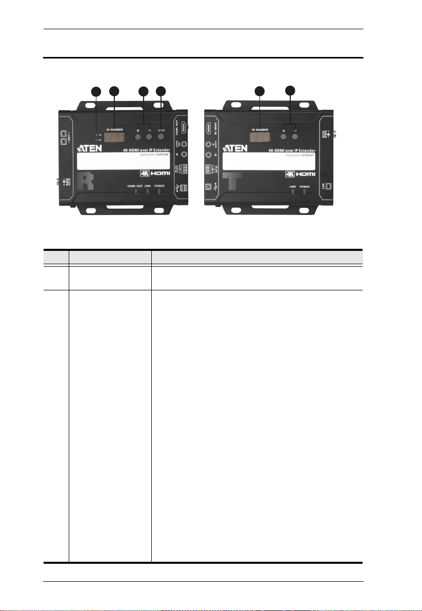
1
2
4
2
3
3
VE8950 Receiver
VE8950 Transmitter
Panel Controls
No. Name Description
1. Tx/Rx LEDs Lights to indicate whether the displayed ID number is of
2. ID Number
Tx or Rx.
Transmitter side: Identifies its ID number.
Receiver side:
Identifies its ID number or the transmitter’s ID
number when the panel control is switched to
Tx.
If the ID number exceeds 3 digits, letter A, b, c,
d, E, and F are used to replace the first two
digits.
A= 10, A00 ~ A99 to display ID number 1000 ~
1099.
b= 11, b00 ~ b99 to display ID number 1100 ~
1199.
c= 12, c00 ~ c99 to display ID number 1200 ~
1299.
d= 13, d00 ~ d99 to display ID number 1300 ~
1399.
E= 14, E00 ~ E99 to display ID number 1400 ~
1499.
F= 15, F00 ~ F99 to display ID number 1500 ~
1599.
An ID Number blinks to indicate that it is been used by
another VE8900 / VE8950 device.
16

Chapter 3. Panel Operation
No. Name Description
3. Up (+) / Down (-)
Buttons
4. Tx/Rx Switch Button Press to switch control between a receiver and its
Assign ID numbers on VE8900 / VE8950 devices.
Assign the source video (transmitter) for the receiver
corresponding transmitter.
Note:
The VE8900 / VE8950 device automatically locks its panel when it idles
for 1 minute. To unlock the panel, press and hold the Down (-) button for 3
seconds.
Tx/Rx LEDs and Tx/Rx Switch Button are only available on VE8900 /
VE8950 receivers.
17

VE8900 / VE8950 User Manual
Assigning Sources Using the Device Panel
1. Assign an ID number to each of your VE8900R / VE8950R devices.
a) On a VE8900R / VE8950R device, make sure the control is switched to
Rx, in which case the Rx LED lights up. If not, press the Tx/Rx switch
button.
b) Use the Up (+) and Down (-) buttons to assign an ID number to this
receiver.
c) Repeat steps 1 (a) and 1 (b) on each of your VE8900R / VE8950R
devices.
2. For a matrix setup, assign an ID number to each of your VE8900T /
VE8950T devices.
a) On a VE8900T / VE8950T device, use the Up (+) and Down (-) buttons
to assign an ID number to this transmitter.
b) Repeat step 2 (a) on each of your VE8900T / VE8950T devices.
3. Assign source inputs to your VE8900R / VE8950R devices.
a) On a VE8900R / VE8950R device, press the Tx/Rx switch button to
switch the control to Tx, in which case the Tx LED lights up.
b) Use the Up (+) and Down (-) buttons to assign a source input to this
receiver.
c) Repeat steps 3 (a) and 3 (b) on each of your VE8900R / VE8950R
devices.
18

Chapter 4
Management
Overview
ATEN VE8900 / VE8950 HDMI over IP Video Extenders can be remotely and
centrally managed using a built-in utility program, the ATEN VE Manager.
Accessed through a web browser, this utility provides a central platform that
allows you to do the following:
Feature Details
Configure transmitter and receiver
settings
Monitor transmitter and receiver
statuses
Create display templates See Creating a Video Wall Layout,
See Transmitter Settings, page 49 and
Receiver Settings, page 51.
See Checking VE8900 / VE8950
Statuses, page 46.
page 34.
19

VE8900 / VE8950x User Manual
Looking Up the Login IP Address
Follow the steps below to download IP Installer utility, and use the utility to
look up the IP address of your VE8900 / VE8950 transmitter.
1. Go to the download link below:
https://www.aten.com/global/en/supportcenter/downloads/
2. Type in VE8900 in the field below “Download materials for other
products” and press OK.
3. Scroll down the page and click either VE8900T or VE8900R.
4. Scroll down the page to find IP Installer zip file under “Software &
Drivers”. Click the file to download.
5. Unzip and execute the downloaded IP Installer. The Network Device IP
Installer screen appears.
6. Click Enumerate to search for ATEN devices in the network. The
detected devices are shown in Device List.
7. Use the IP address of any VE8900 / VE8950 transmitter to log in VE
Manager.
20
 Loading...