

ATEN VE829 User guide
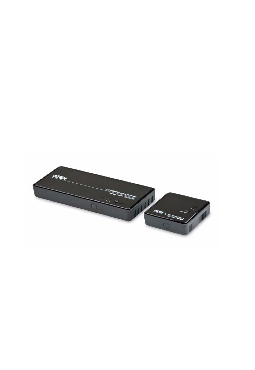
5x2 HDMI Wireless Extender
VE829
User Manual
www.aten.com
VE829 User Manual
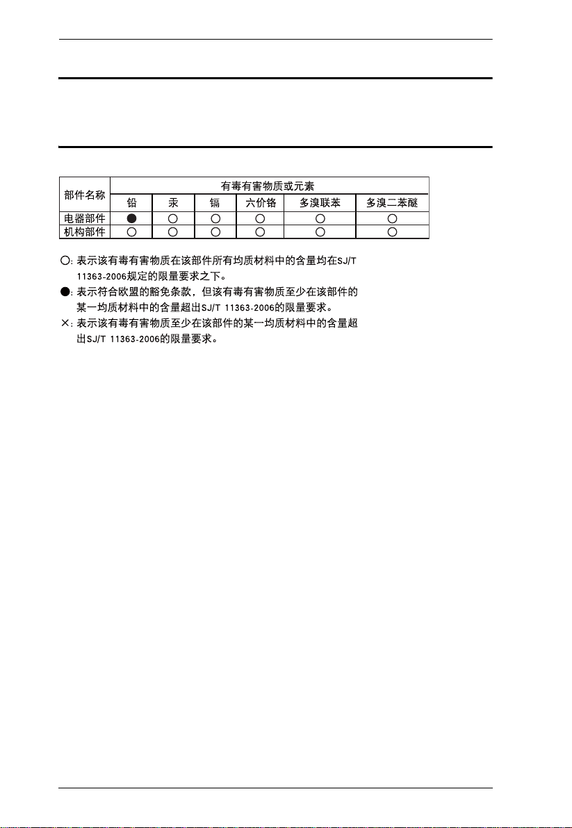
RoHS
This product is RoHS compliant.
SJ/T 11364-2006
The following contains information that relates to China.
ii

VE829 User Manual
User Information
Online Registration
Be sure to register your product at our online support center:
International http://eservice.aten.com
Telephone Support
For telephone support, call this number:
International 886-2-8692-6959
China 86-10-5255-0110
Japan 81-3-5615-5811
Korea 82-2-467-6789
North America 1-888-999-ATEN ext 4988
United Kingdom 44-8-4481-58923
User Notice
All information, documentation, and specifications contained in this manual
are subject to change without prior notification by the manufacturer. The
manufacturer makes no representations or warranties, either expressed or
implied, with respect to the contents hereof and specifically disclaims any
warranties as to merchantability or fitness for any particular purpose. Any of
the manufacturer's software described in this manual is sold or licensed as is.
Should the programs prove defective following their purchase, the buyer (and
not the manufacturer, its distributor, or its dealer), assumes the entire cost of all
necessary servicing, repair and any incidental or consequential damages
resulting from any defect in the software.
The manufacturer of this system is not responsible for any radio and/or TV
interference caused by unauthorized modifications to this device. It is the
responsibility of the user to correct such interference.
The manufacturer is not responsible for any damage incurred in the operation
of this system if the correct operational voltage setting was not selected prior
to operation. PLEASE VERIFY THAT THE VOLTAGE SETTING IS
CORRECT BEFORE USE.
iii

VE829 User Manual
Package Contents
The VE829 package consists of:
1 VE829T 5x2 HDMI Wireless Extender
1 VE829R 5x2 HDMI Wireless Extender
2 IR Remote Control with batteries
1 Component Adapter Cable
1 IR Blaster Cable (Transmitter)
1 IR Sensor Extender Cable (Receiver)
1 HDMI cable
2 Power Adapter
1 User Instructions*
Check to make sure that all the components are present and that nothing got
damaged in shipping. If you encounter a problem, contact your dealer.
Read this manual thoroughly and follow the installation and operation
procedures carefully to prevent any damage to the unit, and/or any of the
devices connected to it.
* Features may have been added to the VE829 since this manual was printed.
Please visit our website to download the most up-to-date version.
© Copyright 2013 ATEN® International Co., Ltd.
ATEN and the ATEN logo are registered trademarks of ATEN International Co., Ltd. All rights reserved.
All other brand names and trademarks are the registered property of their respective owne rs.
iv
Manual Date: 2013-10-02

VE829 User Manual
Contents
User Information . . . . . . . . . . . . . . . . . . . . . . . . . . . . . . . . . . . . . . . . . . . . iii
Online Registration . . . . . . . . . . . . . . . . . . . . . . . . . . . . . . . . . . . . . . . iii
Telephone Support . . . . . . . . . . . . . . . . . . . . . . . . . . . . . . . . . . . . . . . .iii
User Notice . . . . . . . . . . . . . . . . . . . . . . . . . . . . . . . . . . . . . . . . . . . . . .iii
Package Contents. . . . . . . . . . . . . . . . . . . . . . . . . . . . . . . . . . . . . . . . . . . iv
About this Manual . . . . . . . . . . . . . . . . . . . . . . . . . . . . . . . . . . . . . . . . . . . vii
Conventions . . . . . . . . . . . . . . . . . . . . . . . . . . . . . . . . . . . . . . . . . . . . . . viii
Product Information. . . . . . . . . . . . . . . . . . . . . . . . . . . . . . . . . . . . . . . . . . viii
1. Introduction
Overview. . . . . . . . . . . . . . . . . . . . . . . . . . . . . . . . . . . . . . . . . . . . . . . . . . .1
Features . . . . . . . . . . . . . . . . . . . . . . . . . . . . . . . . . . . . . . . . . . . . . . . . . . 2
Requirements . . . . . . . . . . . . . . . . . . . . . . . . . . . . . . . . . . . . . . . . . . . . . . 3
Consoles . . . . . . . . . . . . . . . . . . . . . . . . . . . . . . . . . . . . . . . . . . . . . . . 3
Sources. . . . . . . . . . . . . . . . . . . . . . . . . . . . . . . . . . . . . . . . . . . . . . . . .3
Cables. . . . . . . . . . . . . . . . . . . . . . . . . . . . . . . . . . . . . . . . . . . . . . . . . .3
Components . . . . . . . . . . . . . . . . . . . . . . . . . . . . . . . . . . . . . . . . . . . . . . . 4
VE829T Top View . . . . . . . . . . . . . . . . . . . . . . . . . . . . . . . . . . . . . .4
VE829R Top View . . . . . . . . . . . . . . . . . . . . . . . . . . . . . . . . . . . . . 5
VE829R Rear View . . . . . . . . . . . . . . . . . . . . . . . . . . . . . . . . . . . . .6
Front View . . . . . . . . . . . . . . . . . . . . . . . . . . . . . . . . . . . . . . . . . . . .7
2. Hardware Setup
Wall Mounting . . . . . . . . . . . . . . . . . . . . . . . . . . . . . . . . . . . . . . . . . . . . . . .9
Single Station Installation . . . . . . . . . . . . . . . . . . . . . . . . . . . . . . . . . . . . 11
IR Blaster Extender Cable Setup . . . . . . . . . . . . . . . . . . . . . . . . . . . 13
Transmitter. . . . . . . . . . . . . . . . . . . . . . . . . . . . . . . . . . . . . . . . . . 13
Receiver . . . . . . . . . . . . . . . . . . . . . . . . . . . . . . . . . . . . . . . . . . . .13
3. Basic Operation
Overview. . . . . . . . . . . . . . . . . . . . . . . . . . . . . . . . . . . . . . . . . . . . . . . . . .15
Transmitter and Receiver Link . . . . . . . . . . . . . . . . . . . . . . . . . . . . . . . . .15
Manual Switching . . . . . . . . . . . . . . . . . . . . . . . . . . . . . . . . . . . . . . . . . . 16
Front Panel Pushbutton. . . . . . . . . . . . . . . . . . . . . . . . . . . . . . . . . . . .16
Remote Control. . . . . . . . . . . . . . . . . . . . . . . . . . . . . . . . . . . . . . . . . .16
LED Display. . . . . . . . . . . . . . . . . . . . . . . . . . . . . . . . . . . . . . . . . . . . 17
Naming Source Devices . . . . . . . . . . . . . . . . . . . . . . . . . . . . . . . . . . . . . 18
Device Pairing. . . . . . . . . . . . . . . . . . . . . . . . . . . . . . . . . . . . . . . . . . . . . .18
Powering Off and Restarting. . . . . . . . . . . . . . . . . . . . . . . . . . . . . . . . . . 19
v

VE829 User Manual
4. OSD Operation
Overview. . . . . . . . . . . . . . . . . . . . . . . . . . . . . . . . . . . . . . . . . . . . . . . . . . 21
Source Device Switching . . . . . . . . . . . . . . . . . . . . . . . . . . . . . . . . . . . . .21
Adding and Selecting Active Transmitter . . . . . . . . . . . . . . . . . . . . . . . . . 21
Remove Transmitter . . . . . . . . . . . . . . . . . . . . . . . . . . . . . . . . . . . . . 23
Modify Transmitter Name . . . . . . . . . . . . . . . . . . . . . . . . . . . . . . . . . .23
Appendix
Safety Instructions . . . . . . . . . . . . . . . . . . . . . . . . . . . . . . . . . . . . . . . . . .25
Technical Support. . . . . . . . . . . . . . . . . . . . . . . . . . . . . . . . . . . . . . . . . . 27
International . . . . . . . . . . . . . . . . . . . . . . . . . . . . . . . . . . . . . . . . . . . 27
North America. . . . . . . . . . . . . . . . . . . . . . . . . . . . . . . . . . . . . . . . . . 27
Specifications . . . . . . . . . . . . . . . . . . . . . . . . . . . . . . . . . . . . . . . . . . . . . 28
Video and Audio Format Supported . . . . . . . . . . . . . . . . . . . . . . . . . 29
Troubleshooting . . . . . . . . . . . . . . . . . . . . . . . . . . . . . . . . . . . . . . . . . . . 30
Limited Warranty. . . . . . . . . . . . . . . . . . . . . . . . . . . . . . . . . . . . . . . . . . . . 32
vi

VE829 User Manual
About this Manual
This User Manual is provided to help you get the most from your system. It
covers all aspects of installation, configuration and operation. An overview of
the information found in the manual is provided below.
Chapter 1, Introduction, introduces you to the VE829 system. Its purpose,
features and benefits are presented, and its front and back panel components
are described.
Chapter 2, Hardware Setup, describes how to set up your installation.
Diagrams showing the necessary steps are provided.
Chapter 3, Basic Operation, explains the fundamental concepts involved
in operating the VE829.
Chapter 4, OSD Operation, provides a complete description of the
VE829’s On-Screen Display (OSD), and how to work with it.
An Appendix, provides specifications and other technical information
regarding the VE829.
vii

VE829 User Manual
Conventions
This manual uses the following conventions:
Monospaced Indicates text that you should key in.
[ ] Indicates keys you should press. For example, [Enter] means to
press the Enter key. If keys need to be chorded, they appear
together in the same bracket with a plus sign between them:
[Ctrl+Alt].
1. Numbered lists represent procedures with sequential steps.
♦ Bullet lists provide information, but do not involve sequential steps.
→ Indicates selecting the option (on a menu or dialog box, for
example), that comes next. For example, Start
open the Start menu, and then select Run.
Indicates critical information.
Product Information
→ Run means to
For information about all ATEN products and how they can help you connect
without limits, visit ATEN on the Web or contact an ATEN Authorized
Reseller. Visit ATEN on the Web for a list of locations and telephone numbers:
International http://www.aten.com
North America http://www.aten-usa.com
viii

Chapter 1
Introduction
Overview
The VE829 5x2 HDMI Wireless Extender is the first of its kind to send full
uncompressed HD 1080p, while connecting up to 5 source devices and
allowing users to switch and independently select any source to display on two
HDTVs. Its wireless matrix feature is the biggest breakthough in Audio / Video
solutions to date. This means you can watch cable TV in one location
(transmitter side) and, at the same time, independently select a Blu-ray movie
to watch in another location (receiver side). The VE829 is capable of streaming
Full HD 1080p with support for 3D content and digital audio up to 30m away,
within the home or any desired setup.
Note: Distance, quality and signal may vary depending on the environment;
solid structures, such as steel, concrete and brick may result to shorter
distance coverage or complete loss of signal.
The solution consists of a Wireless Transmitter and a Wireless Receiver with
connections for the HDMI and Component, along with a loop through (local
port) for advanced two-HDTV setups. It also features USB HID connectivity
for adding a computer / laptop to the installment, giving you wireless control
from the VE829R. Infrared (IR) pass-through enables wireless control of your
source devices and helps consolidate your HD A/V electronics, such as a
DVDs / Blu-ray players, DVRs / Cable boxes, Game consoles and computers
allowing you to design your own custom entertainment space.
1

VE829 User Manual
Features
Wireless transmission of fully uncompressed HD videos up to 30m for two
HDTVs
Note: Distance, quality and signal may vary depending on the
environment; solid structures, such as steel, concrete and brick may
result to shorter distance coverage or complete loss of signal.
Allows you to switch and independently select any of 5 sources (4 x
HDMI connectors, 1 x component connector) between 2 HDTVs
Supports full uncompressed HD, 1080P, 3D content, and 5.1 channel
digital audio
Superior video quality – 480P, 720P, 1080i, 1080P
USB HID ports on Transmitter and Receiver units enable wireless
keyboard connectivity to control attached computers/laptops
Based on WHDI™ technology – Low latency < 1 ms
HDMI (3D), HDCP compatible
No software or driver installation needed
2

Introduction
Requirements
Consoles
2 HDMI displays with HDMI Type A output connectors
Keyboard / mouse (optional, USB HID function)
Sources
Up to 4 video source devices with an HDMI Type A input connector
1 video source with component output connector
Computer or laptop (optional)
Cables
Up to 4 HDMI cables for the source devices you will be connecting
Note: The package includes 1 HDMI cable.
2 HDMI cables for the display devices you will be using
1 Component adapter cable
1 Component cable (not included with this package)
1 IR Blaster Cable (optional)
1 IR Sensor Extender Cable (optional)
1 mini USB to Type A USB cable (optional)
3
VE829 User Manual
12
3
Components
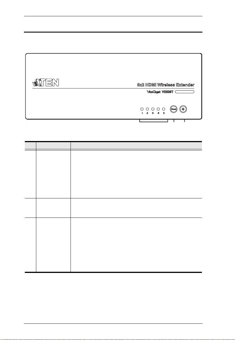
VE829T Top View
No. Component Description
1 Source LEDs These LEDs light green to indicate active connection to a
source.
The LEDs blink to indicate that it is trying to link with a
Receiver.
The LEDs blink quickly when no source is detected.
The LEDs blink slowly if the video from the source cannot be
recognized.
2 Source
Selection
Button
3 Power Button /
LED
Press this to manually switch between ports.
Press this button to power on/off the VE829T.
Note: The HDMI Out on the Transmitter is always ON even
when the Transmitter is in standby mode.
The LED lights green to indicate that the device is receiving
power.
The LED turns red when the device is in standby mode.
The LED blink to indicate that it is trying to link with a
Receiver.
4
Introduction
1
2
3
4
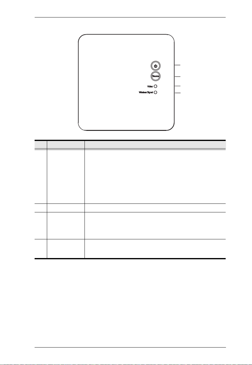
VE829R Top View
No. Component Description
1 Power Button /
LED
2 Source Button Press this to manually switch between ports.
3 Video LED The LED blinks to indicate that the VE829R does not detect an
4 Wireless Signal
LED
Press this button to power on/off the VE829R.
Note: The HDMI Out on the Transmitter is always ON even
when the Receiver is in standby mode.
The LED lights green to indicate that the device is receiving
power.
The LED turns red when the device is in standby mode.
The LED blinks to indicate that it is trying to link with a
Transmitter.
input source and/or the video format is not recognized.
The lights green when the video from the input source is
recognized.
The LED blinks to indicate that it is trying to link with the
Transmitter, and lights green when the connection is
established.
5
 Loading...