

ATEN SN3001, SN3002, SN3001P, SN3002P User guide

User Manual
ATEN Altusen™
SN3001 / SN3001P
SN3002 / SN3002P
RS-232 Secure Device Server

Secure Device Server User Manual
EMC Information
FEDERAL COMMUNICATIONS COMMISSION INTERFERENCE
STATEMENT
This equipment has been tested and found to comply with the limits for a Class
A digital device, pursuant to Part 15 of the FCC Rules. These limits are
designed to provide reasonable protection against harmful interference when
the equipment is operated in a commercial environment. This equipment
ge nerates , uses, and can radia te radio f requenc y energy a nd, if not installed and
used in accordance with the instruction manual, may cause harmful
interference to radio communications. Operation of this equipment in a
residential area is likely to cause harmful interference in which case the user
will be required to correct the interference at his own expense.
This device complies with Part 15 of the FCC Rules. Operation is subject to the
following two conditions: (1) this device may not cause harmful interference,
and (2) this device must accept any interference received, including
interference that may cause undesired operation.
FCC Caution
Any changes or modifications not expressly approved by the party responsible
for compliance could void the user's authority to operate this equipment.
Warning
Operation of this equipment in a residential environment could cause radio
interference.
Achtung
Der Gebrauch dieses Geräts in Wohnumgebung kann Funkstörungen
verursachen.
KCC Statement:
Industry Canada Statement
This Class A digital apparatus complies with Canadian ICES-003.
ii
Secure Device Server User Manual
RoHS
This product is RoHS compliant.
About This Manual
This manual is provided to help you get the most out of your Secure Device
Server. It covers all aspects of the device, including installation, configuration,
and operation.
The Secure Device Server models covered in this user manuals include:
Models Product Names
SN3001 1-Port RS-232 Secure Device Server
SN3001P 1-Port RS-232 Secure Device Server with PoE
SN3002 2-Port RS-232 Secure Device Server
SN3002P 2-Port RS-232 Secure Device Server with PoE
An overview of the information found in the manual is provided below.
Chapter 1, Introduction, introduces Secure Device Server. Its purpose,
features and benefits are presented, and its front and back panel components
are described.
Chapter 2, Hardware Setup, provides step-by-step instructions for setting
up Secure Device Server.
Chapter 3, Network Configuration and Login, explains how to log into
the Secure Device Server from a web browser.
Chapter 4, Web Console, explains the administrative procedures that are
employed to configure the Secure Device Server’s working environment.
Chapter 5, User Management, details login accounts and third-party
authentication services supported, such as RADIUS.
Chapter 6, Port Operating Modes, introduces the Secure Device Server’s
operating modes, and explains the purpose of each.
Chapter 7, Port Access, describes how to access the COM ports of the
Secure Device Server and start SNViewer.
iii

Secure Device Server User Manual
Chapter 8, Remote Terminal Operation, describes how the Secure
Device Server can be accessed via remote terminal sessions, such as Telnet,
SSH, and PuTTY.
Chapter 9, Virtual Serial Port Manager, shows how to install the virtual
COM port driver and to set up and manage the virtual COM port.
Chapter 10, Serial Network Device Manager, explains how to use the
Serial Network Device Management utility to create and maintain device
groups for easy management of the serial ports on your installation; and as an
AP alternative to the browser-based management utilities.
Appendix, provides technical and troubleshooting information at the end of
the manual.
Conventions
This manual uses the following conventions:
Monospaced Indicates text that you should key in.
[ ] Indicates keys you should press. For example, [Enter] means to
1. Numbered lists represent procedures with sequential steps.
♦ Bullet lists provide information, but do not involve sequential
> Indicates selecting an option (such as on a menu or dialog box),
press the Enter key. If keys need to be chorded, they appear
together in the same bracket with a plus sign between them:
[Ctrl+Alt].
steps.
>
that comes next. For example, Start
Start menu, and then select Run.
Indicates critical information.
Run means to open the
iv

Secure Device Server User Manual
Package Contents
SN3001 / SN3002
The standard SN3001 / SN3002 package consists of:
1 Secure Device Server (SN3001 / SN3002)
1 power adapter
1 terminal block
1 foot pad set (4 pcs)
1 DIN rail mount kit
1 user instructions*
SN3001P / SN3002P
The standard SN3001P / SN3002P package consists of:
1 Secure Device Server with PoE (SN3001P / SN3002P)
1 terminal block
1 foot pad set (4 pcs)
1 DIN rail mount kit
1 user instructions*
Check to make sure that all of the components are present and in good order.
If anything is missing, or was damaged in shipping, contact your dealer for
assistance.
Read this manual thoroughly and follow the installation and operation
procedures carefully to avoid any damage to the Secure Device Server or to any
other devices on the Secure Device Server installation.
* Features may have been added to the Secure Device Server since this manual
was released. Please visit our website to download the most up to date
version of the manual.
v
Secure Device Server User Manual
Product Information
For information about all ATEN products and how they can help you connect
without limits, visit ATEN on the web or contact an ATEN authorized reseller.
Visit ATEN on the web for a list of locations and telephone numbers:
International http://www.aten.com
North America http://www.aten-usa.com
User Information
Online Registration
Be sure to register your product at our online support center:
International http://eservice.aten.com
Telephone Support
For telephone support, call this number:
International 886-2-8692-6959
China 86-400-810-0-810
Japan 81-3-5615-5811
Korea 82-2-467-6789
North America 1-888-999-ATEN ext 4988
1- 949-428-1111
vi

Secure Device Server User Manual
User Notice
All information, documentation, and specifications contained in this manual
are subject to change without prior notification by the manufacturer. The
manufacturer makes no representations or warranties, either expressed or
implied, with respect to the contents hereof and specifically disclaims any
warranties as to merchantability or fitness for any particular purpose. Any of
the manufacturer's software described in this manual is sold or licensed as is.
Should the programs prove defective following their purchase, the buyer (and
not the manufacturer, its distributor, or its dealer), assumes the entire cost of all
necessary servicing, repair and any incidental or consequential damages
resulting from any defect in the software.
The manufacturer of this system is not responsible for any radio and/or TV
interference caused by unauthorized modifications to this device. It is the
responsibility of the user to correct such interference.
The manufacturer is not responsible for any damage incurred in the operation
of this system if the correct operational voltage setting was not selected prior
to operation. PLEASE VERIFY THAT THE VOLTAGE SETTING IS
CORRECT BEFORE USE.
vii

Secure Device Server User Manual
Contents
EMC Information. . . . . . . . . . . . . . . . . . . . . . . . . . . . . . . . . . . . . . . . . . . . . ii
About This Manual . . . . . . . . . . . . . . . . . . . . . . . . . . . . . . . . . . . . . . . . . . .iii
Conventions . . . . . . . . . . . . . . . . . . . . . . . . . . . . . . . . . . . . . . . . . . . . .iv
Package Contents . . . . . . . . . . . . . . . . . . . . . . . . . . . . . . . . . . . . . . . . . . . v
SN3001 / SN3002 . . . . . . . . . . . . . . . . . . . . . . . . . . . . . . . . . . . . . . . . . v
SN3001P / SN3002P . . . . . . . . . . . . . . . . . . . . . . . . . . . . . . . . . . . . . . v
Product Information . . . . . . . . . . . . . . . . . . . . . . . . . . . . . . . . . . . . . . . . . .vi
User Information . . . . . . . . . . . . . . . . . . . . . . . . . . . . . . . . . . . . . . . . . . . . .vi
Online Registration . . . . . . . . . . . . . . . . . . . . . . . . . . . . . . . . . . . . . . . .vi
Telephone Support . . . . . . . . . . . . . . . . . . . . . . . . . . . . . . . . . . . . . . . .vi
User Notice . . . . . . . . . . . . . . . . . . . . . . . . . . . . . . . . . . . . . . . . . . . . . vii
Contents . . . . . . . . . . . . . . . . . . . . . . . . . . . . . . . . . . . . . . . . . . . . . . . . . . viii
Chapter 1.
Introduction
Overview. . . . . . . . . . . . . . . . . . . . . . . . . . . . . . . . . . . . . . . . . . . . . . . . . . . 1
Features . . . . . . . . . . . . . . . . . . . . . . . . . . . . . . . . . . . . . . . . . . . . . . . . . . . 2
Serial-to-Ethernet Connectivity . . . . . . . . . . . . . . . . . . . . . . . . . . . . . . . 2
Hardware. . . . . . . . . . . . . . . . . . . . . . . . . . . . . . . . . . . . . . . . . . . . . . . . 2
Security . . . . . . . . . . . . . . . . . . . . . . . . . . . . . . . . . . . . . . . . . . . . . . . . . 3
System Management . . . . . . . . . . . . . . . . . . . . . . . . . . . . . . . . . . . . . . 3
SN3001 / SN3001P / SN3002 / SN3002P Front View . . . . . . . . . . . . . . . . 4
SN3001 / SN3001P / SN3002 / SN3002P Rear View . . . . . . . . . . . . . . . . 4
SN3001 / SN3001P / SN3002 / SN3002P Top View . . . . . . . . . . . . . . . . . 5
Chapter 2.
Hardware Setup
Before you Begin . . . . . . . . . . . . . . . . . . . . . . . . . . . . . . . . . . . . . . . . . . . . 7
Placement Options . . . . . . . . . . . . . . . . . . . . . . . . . . . . . . . . . . . . . . . . . . . 7
Wall Mount . . . . . . . . . . . . . . . . . . . . . . . . . . . . . . . . . . . . . . . . . . . . . . 7
DIN Rail Mount . . . . . . . . . . . . . . . . . . . . . . . . . . . . . . . . . . . . . . . . . . . 8
Parallel DIN Rail Mount. . . . . . . . . . . . . . . . . . . . . . . . . . . . . . . . . . 8
Perpendicular DIN Rail Mount . . . . . . . . . . . . . . . . . . . . . . . . . . . . . 9
Rack Mount. . . . . . . . . . . . . . . . . . . . . . . . . . . . . . . . . . . . . . . . . . . . . 10
Installation. . . . . . . . . . . . . . . . . . . . . . . . . . . . . . . . . . . . . . . . . . . . . . . . . 13
Serial Port Pin Assignments . . . . . . . . . . . . . . . . . . . . . . . . . . . . . . . . . . . 15
Chapter 3.
Network Configuration and Login
IP Address Determination. . . . . . . . . . . . . . . . . . . . . . . . . . . . . . . . . . . . . 17
viii

Secure Device Server User Manual
IP Installer Utility . . . . . . . . . . . . . . . . . . . . . . . . . . . . . . . . . . . . . . . . . 17
Without IP Installer (non-DHCP only) . . . . . . . . . . . . . . . . . . . . . . . . .18
Logging In . . . . . . . . . . . . . . . . . . . . . . . . . . . . . . . . . . . . . . . . . . . . . . . . . 19
Quick Setup Wizard . . . . . . . . . . . . . . . . . . . . . . . . . . . . . . . . . . . . . . . . . 20
General . . . . . . . . . . . . . . . . . . . . . . . . . . . . . . . . . . . . . . . . . . . . . . . .20
Network . . . . . . . . . . . . . . . . . . . . . . . . . . . . . . . . . . . . . . . . . . . . . . . . 21
Serial . . . . . . . . . . . . . . . . . . . . . . . . . . . . . . . . . . . . . . . . . . . . . . . . . . 22
Chapter 4.
Web Console
Web Interface . . . . . . . . . . . . . . . . . . . . . . . . . . . . . . . . . . . . . . . . . . . . . . 23
Serial Ports . . . . . . . . . . . . . . . . . . . . . . . . . . . . . . . . . . . . . . . . . . . . . . . . 24
Editing Serial Ports . . . . . . . . . . . . . . . . . . . . . . . . . . . . . . . . . . . . . . .24
Properties . . . . . . . . . . . . . . . . . . . . . . . . . . . . . . . . . . . . . . . . . . . 25
Port Buffering. . . . . . . . . . . . . . . . . . . . . . . . . . . . . . . . . . . . . . . . . 26
Operating Mode. . . . . . . . . . . . . . . . . . . . . . . . . . . . . . . . . . . . . . .27
Network. . . . . . . . . . . . . . . . . . . . . . . . . . . . . . . . . . . . . . . . . . . . . . . . . . . 32
System . . . . . . . . . . . . . . . . . . . . . . . . . . . . . . . . . . . . . . . . . . . . . . . . . . .33
General Settings . . . . . . . . . . . . . . . . . . . . . . . . . . . . . . . . . . . . . . . . .34
General . . . . . . . . . . . . . . . . . . . . . . . . . . . . . . . . . . . . . . . . . . . . .34
Time. . . . . . . . . . . . . . . . . . . . . . . . . . . . . . . . . . . . . . . . . . . . . . . . 36
Notification. . . . . . . . . . . . . . . . . . . . . . . . . . . . . . . . . . . . . . . . . . . . . . 37
SMTP. . . . . . . . . . . . . . . . . . . . . . . . . . . . . . . . . . . . . . . . . . . . . . . 37
SNMP . . . . . . . . . . . . . . . . . . . . . . . . . . . . . . . . . . . . . . . . . . . . . . 38
Syslog . . . . . . . . . . . . . . . . . . . . . . . . . . . . . . . . . . . . . . . . . . . . . .39
Advanced. . . . . . . . . . . . . . . . . . . . . . . . . . . . . . . . . . . . . . . . . . . .40
Security . . . . . . . . . . . . . . . . . . . . . . . . . . . . . . . . . . . . . . . . . . . . . . . . 41
Access Protection (IP Filter) . . . . . . . . . . . . . . . . . . . . . . . . . . . . .41
Security Level . . . . . . . . . . . . . . . . . . . . . . . . . . . . . . . . . . . . . . . . 42
Account Policy . . . . . . . . . . . . . . . . . . . . . . . . . . . . . . . . . . . . . . . . 42
Security Certificate. . . . . . . . . . . . . . . . . . . . . . . . . . . . . . . . . . . . .43
Update & Restore . . . . . . . . . . . . . . . . . . . . . . . . . . . . . . . . . . . . . . . . 44
Firmware Update . . . . . . . . . . . . . . . . . . . . . . . . . . . . . . . . . . . . . . 44
Backup & Restore . . . . . . . . . . . . . . . . . . . . . . . . . . . . . . . . . . . . . 45
User Accounts. . . . . . . . . . . . . . . . . . . . . . . . . . . . . . . . . . . . . . . . . . . . . .46
Logs . . . . . . . . . . . . . . . . . . . . . . . . . . . . . . . . . . . . . . . . . . . . . . . . . . . . .47
Chapter 5.
User Management
Overview . . . . . . . . . . . . . . . . . . . . . . . . . . . . . . . . . . . . . . . . . . . . . . . . . .49
User. . . . . . . . . . . . . . . . . . . . . . . . . . . . . . . . . . . . . . . . . . . . . . . . . . . . . . 49
Adding Users. . . . . . . . . . . . . . . . . . . . . . . . . . . . . . . . . . . . . . . . . . . .50
Editing Users. . . . . . . . . . . . . . . . . . . . . . . . . . . . . . . . . . . . . . . . . . . .51
Deleting Users. . . . . . . . . . . . . . . . . . . . . . . . . . . . . . . . . . . . . . . . . . .52
ix

Secure Device Server User Manual
Online Users . . . . . . . . . . . . . . . . . . . . . . . . . . . . . . . . . . . . . . . . . . . . 52
Authentication Services . . . . . . . . . . . . . . . . . . . . . . . . . . . . . . . . . . . . . . 53
RADIUS. . . . . . . . . . . . . . . . . . . . . . . . . . . . . . . . . . . . . . . . . . . . . . . . 53
Chapter 6.
Port Operating Modes
Overview. . . . . . . . . . . . . . . . . . . . . . . . . . . . . . . . . . . . . . . . . . . . . . . . . . 55
Selecting Operating Mode . . . . . . . . . . . . . . . . . . . . . . . . . . . . . . . . . . . . 55
Operating Mode . . . . . . . . . . . . . . . . . . . . . . . . . . . . . . . . . . . . . . . . . . . . 57
Real COM . . . . . . . . . . . . . . . . . . . . . . . . . . . . . . . . . . . . . . . . . . . . . . 57
TCP Server & Client . . . . . . . . . . . . . . . . . . . . . . . . . . . . . . . . . . . . . . 57
TCP Server . . . . . . . . . . . . . . . . . . . . . . . . . . . . . . . . . . . . . . . . . . 57
TCP Client . . . . . . . . . . . . . . . . . . . . . . . . . . . . . . . . . . . . . . . . . . . 58
Serial Tunneling Server & Client . . . . . . . . . . . . . . . . . . . . . . . . . . . . . 58
UDP Mode. . . . . . . . . . . . . . . . . . . . . . . . . . . . . . . . . . . . . . . . . . . . . . 58
Console Management. . . . . . . . . . . . . . . . . . . . . . . . . . . . . . . . . . . . . 59
Console Management Direct. . . . . . . . . . . . . . . . . . . . . . . . . . . . . . . . 59
Disable . . . . . . . . . . . . . . . . . . . . . . . . . . . . . . . . . . . . . . . . . . . . . . . . 60
Chapter 7.
Port Access
Overview. . . . . . . . . . . . . . . . . . . . . . . . . . . . . . . . . . . . . . . . . . . . . . . . . . 61
Telnet / SSH . . . . . . . . . . . . . . . . . . . . . . . . . . . . . . . . . . . . . . . . . . . . . . . 62
SNViewer . . . . . . . . . . . . . . . . . . . . . . . . . . . . . . . . . . . . . . . . . . . . . . 62
Control Panel Functions . . . . . . . . . . . . . . . . . . . . . . . . . . . . . . . . 63
Data Import . . . . . . . . . . . . . . . . . . . . . . . . . . . . . . . . . . . . . . . . . . 64
Encode . . . . . . . . . . . . . . . . . . . . . . . . . . . . . . . . . . . . . . . . . . . . . 64
Terminal Settings . . . . . . . . . . . . . . . . . . . . . . . . . . . . . . . . . . . . . 64
Chapter 8.
Remote Terminal Operation
Overview. . . . . . . . . . . . . . . . . . . . . . . . . . . . . . . . . . . . . . . . . . . . . . . . . . 67
Terminal Login . . . . . . . . . . . . . . . . . . . . . . . . . . . . . . . . . . . . . . . . . . . . . 67
Telnet Login . . . . . . . . . . . . . . . . . . . . . . . . . . . . . . . . . . . . . . . . . . . . 67
SSH Login (Linux). . . . . . . . . . . . . . . . . . . . . . . . . . . . . . . . . . . . . . . . 68
Third-party Utility (Windows) . . . . . . . . . . . . . . . . . . . . . . . . . . . . . . . . 68
Terminal Main Menu. . . . . . . . . . . . . . . . . . . . . . . . . . . . . . . . . . . . . . . . . 69
Chapter 9.
Virtual Serial Port Manager
Overview. . . . . . . . . . . . . . . . . . . . . . . . . . . . . . . . . . . . . . . . . . . . . . . . . . 71
x

Secure Device Server User Manual
Real COM Port Management — Virtual Serial Port Manager. . . . . . . . . .72
Utility Interface. . . . . . . . . . . . . . . . . . . . . . . . . . . . . . . . . . . . . . . . . . . 72
Menu and Toolbar . . . . . . . . . . . . . . . . . . . . . . . . . . . . . . . . . . . . .73
Target Information . . . . . . . . . . . . . . . . . . . . . . . . . . . . . . . . . . . . .73
Target List . . . . . . . . . . . . . . . . . . . . . . . . . . . . . . . . . . . . . . . . . . .74
Port List . . . . . . . . . . . . . . . . . . . . . . . . . . . . . . . . . . . . . . . . . . . . . 75
Port Mapping and Unmapping. . . . . . . . . . . . . . . . . . . . . . . . . . . . . . . 76
Port Mapping . . . . . . . . . . . . . . . . . . . . . . . . . . . . . . . . . . . . . . . . . 76
Mapped COM Port. . . . . . . . . . . . . . . . . . . . . . . . . . . . . . . . . . . . . 76
Port Unmapping. . . . . . . . . . . . . . . . . . . . . . . . . . . . . . . . . . . . . . . 77
Real COM Port Management — Linux Commands . . . . . . . . . . . . . . . . . 78
Mapping / Unmapping Virtual Ports. . . . . . . . . . . . . . . . . . . . . . . . . . . 78
Virtual Port Naming Rules. . . . . . . . . . . . . . . . . . . . . . . . . . . . . . . . . . 78
Appendix
Safety Instructions. . . . . . . . . . . . . . . . . . . . . . . . . . . . . . . . . . . . . . . . . . . 79
General . . . . . . . . . . . . . . . . . . . . . . . . . . . . . . . . . . . . . . . . . . . . . . . .79
DC Power . . . . . . . . . . . . . . . . . . . . . . . . . . . . . . . . . . . . . . . . . . . . . .81
Rack Mounting . . . . . . . . . . . . . . . . . . . . . . . . . . . . . . . . . . . . . . . . . . 82
Technical Support . . . . . . . . . . . . . . . . . . . . . . . . . . . . . . . . . . . . . . . . . . .83
International. . . . . . . . . . . . . . . . . . . . . . . . . . . . . . . . . . . . . . . . . . . . . 83
North America . . . . . . . . . . . . . . . . . . . . . . . . . . . . . . . . . . . . . . . . . . . 83
Specifications . . . . . . . . . . . . . . . . . . . . . . . . . . . . . . . . . . . . . . . . . . . . . .84
Clear Login Information. . . . . . . . . . . . . . . . . . . . . . . . . . . . . . . . . . . . . . .86
Troubleshooting . . . . . . . . . . . . . . . . . . . . . . . . . . . . . . . . . . . . . . . . . . . . 87
Limited Warranty. . . . . . . . . . . . . . . . . . . . . . . . . . . . . . . . . . . . . . . . . . . . 88
xi

Secure Device Server User Manual
This Page Intentionally Left Blank
xii

Chapter 1
Introduction
Overview
The Secure Device Server provides security-assuring, IP-based LAN
connectivity for RS-232 serial devices and supports a wide range of operation
modes. It empowers everyday RS-232 serial device — PLCs, meters, and
sensors — to be connected to a network, and allowing them to be accessed and
managed from anywhere over the network.
Equipped with extensive security features, such as Secure Real COM, Secure
TCP Client and Server, Secure Serial Tunneling, and Secure Console
Management, the Secure Device Server is the ideal solution for managing RS232 serial device in a wide range of security-critical applications.
Fully compatible with existing serial communication software, the Secure
Device Server ensures that your former investments in software development
are protected. Software designed to work with COM or TTY ports can access
the serial devices connected over a TCP/IP network by utilizing the Secure
Device Server’s Real COM or TTY drivers. This feature also breaks through
the port number and distance limitation barriers encountered with PC
hardware.
Wi th SSL and SSH proto c ol suppo rt — for e n cryptin g data trans mission — the
Secure Device Server ensures secured data transmission over both private and
public networks.
Installing the Secure Device Server is fast and easy: plugging cables into their
appropriate ports is all that is entailed. It also offers a browser-based GUI,
Telnet / SSH console sessions, and a Windows software utility, making
configuration and operation swift and smooth.
SN3001P / SN3002P provides PoE function, IEEE 802.3af compliant, thus can
be powered through an Ethernet cable, by a PoE switch/adapter, without
requiring an additional power supply.
All in all, with its advanced features and ease of operation, the Secure Device
Server is the most convenient, reliable, and cost-effective way to remotely
manage your serial devices.
1

Secure Device Server User Manual
Features
Serial-to-Ethernet Connectivity
1 or 2 RS-232 serial ports for secured serial data over Ethernet
transmission
Secured operation modes — Secured Real COM, Secured TCP Server/
Client, Secured Serial Tunneling, Console Management (SSH), and
Console Management Direct (SSH)
Standard operation modes — Real COM, TCP Server/Client, Serial
Tunneling, UDP, Console Management (Telnet), and Console
Management Direct (Telnet)
Real COM, Real TTY, and Fixed TTY drivers for Windows, Linux, and
UNIX
Convenient console management access via Java viewer (SSH/Telnet) or
third-party clients such as PuTTY
Easy console port access via Java viewer and Sun Solaris ready (“break-
free”)
Multiple users can simultaneously access the same port — up to 16
connections per port
Hardware
Redundant power input (power jack and terminal block) for fail-safe
power
IEEE 802.3af-compliant PoE power device equipment (SN3001P /
SN3002P only)
Surge protection for serial, Ethernet, and power
Wall and DIN-rail mounting, rack mounting (optional kit VE-RMK1U
required), and desktop installation available
Supports baud rates of 110, 134, 150, 300, 600, 1200, 1800, 2400, 4800,
7200, 9600, 19200, 38400, 57600, 115200, 230.4k, 460.8k, 921.6k bps
2

Chapter 1. Introduction
Security
Supports secured login from browsers with TLS 1.2 data encryption and
RSA 2048-bit certificates
Configurable user permissions for port access and control
Local and remote authentication and login
Third-party authentication (e.g. RADIUS)
IP address filter for security protection
System Management
Browser access with an intuitive GUI
Web-based quick setup wizard for fast configuration
Terminal-based access with a menu-driven UI via Telnet / SSH
Online / offline detection of connected serial devices (including terminal
blocks) — automatically send event notifications when the devices are
offline (e.g. power failure) for device status monitoring
System event logs will be saved to internal memory or Syslog server
Port logs will be saved to internal memory or Syslog server
SNMP agent (v1/v2c)
Event notification — supports notification of SMTP email and SNMP trap
(v1/v2c)
Backup / restore system configuration and upgradable firmware
64 Kbyte port buffer prevents data loss when the network is down
NTP for time server synchronization
Multi-language web-based GUI
3
Secure Device Server User Manual
32
42 5
3
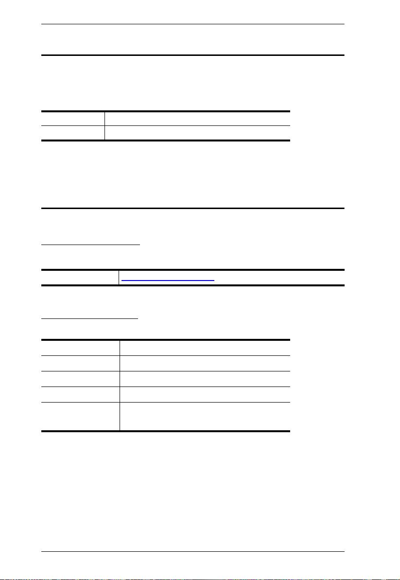
SN3001 / SN3001P / SN3002 / SN3002P Front View
No. Component Description
1 RS-232 serial
port 1
2 RS-232 serial
port 2
Connects to an RS-232 serial device.
Connects to a second RS-232 serial device. (SN3002 /
SN3002P only)
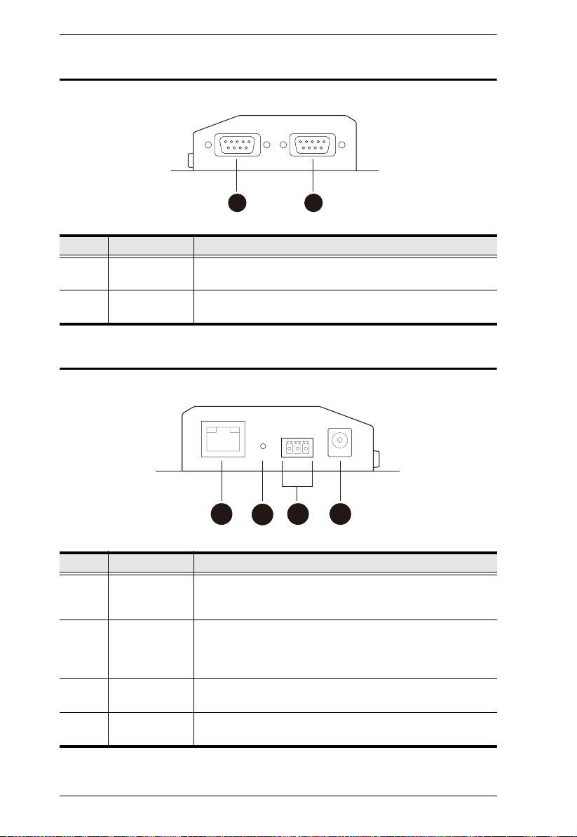
SN3001 / SN3001P / SN3002 / SN3002P Rear View
No. Component Description
1 LAN port Connects the Secure Device Server to the network. For
2 reset button Pressing and holding for less than three seconds performs
3 power terminal Connects the Secure Device Server to power via DC
4 power jack Connects the Secure Device Server to power using a power
4
SN3001P / SN3002P (PoE 802.3af compliant), it can be
simultaneously supplied power through a PoE switch.
a system restart. Pressing and holding for more than three
seconds returns its settings (excluding user account
settings and privileges) to their default status.
electric leads and the terminal block provided.
adapter.
Chapter 1. Introduction
532 64
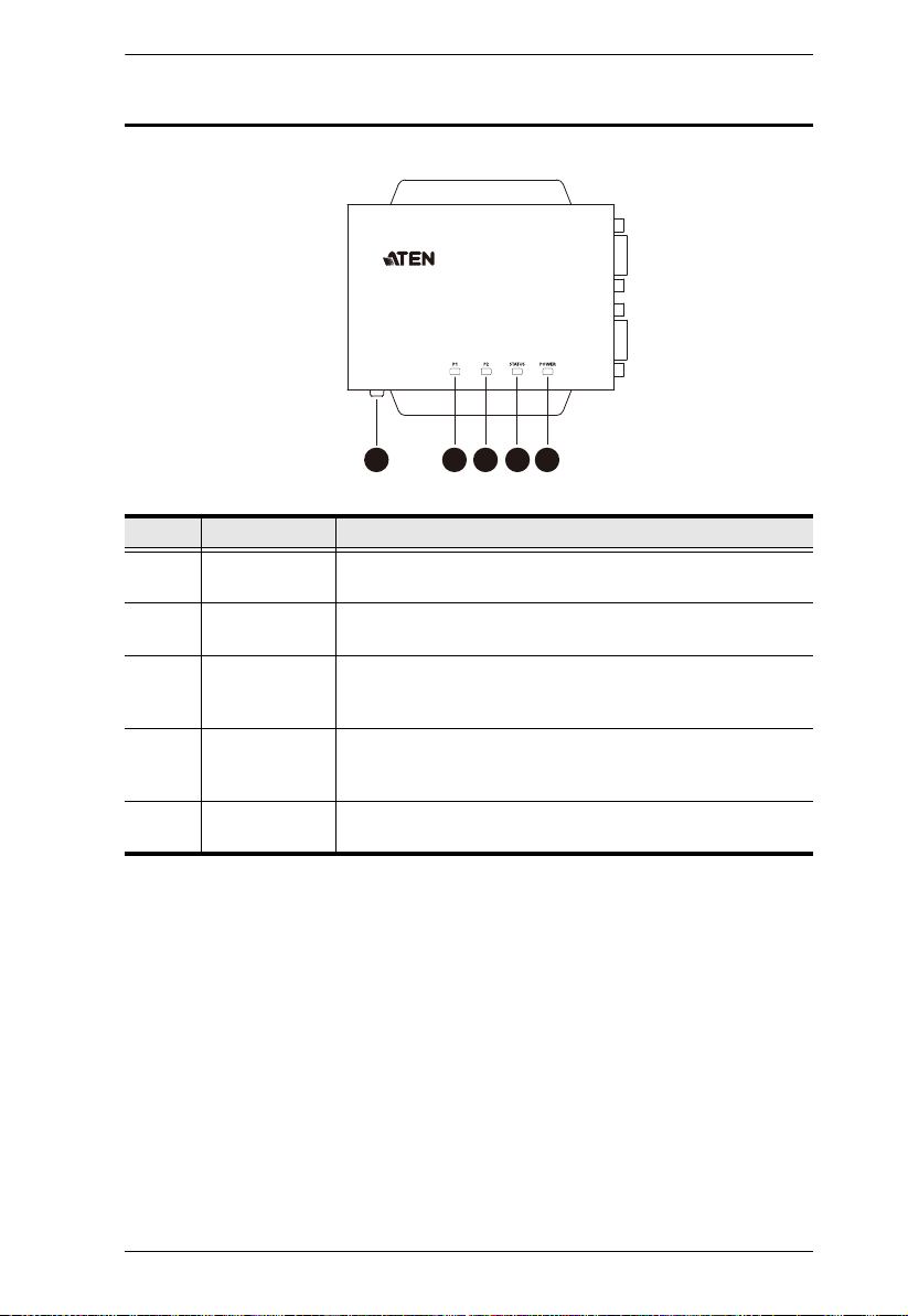
SN3001 / SN3001P / SN3002 / SN3002P Top View
No. Component Description
1 grounding
terminal
2 serial port 1
LED
3 serial port 2
LED
4 status LED Lights or blinks yellow/green respectively for normal
5 power LED Lights green when the Secure Device Server is powered
Grounds the unit by connecting to a suitable grounded
object using a grounding wire.
Lights green or orange when data is being sent or received
via the unit’s RS-232 serial port 1.
Lights green or orange when data is being sent or received
via the unit’s RS-232 serial port 2. (SN3002 / SN3002P
only)
operation or startup, and lights red when an error (i.e.
hardware failure and DHCP irregularity) occurs.
and ready.
5

Secure Device Server User Manual
This Page Intentionally Left Blank
6
Chapter 2
1. Important safety information regarding the placement of this
device is provided on page 79. Please review it before
proceeding.
2. Make sure the power of all devices to be connected have been
turned off.
Hardware Setup
Before you Begin
Placement Options
For flexibility and convenience, Secure Device Server can be mounted onto a
wall or DIN rail, as described below.
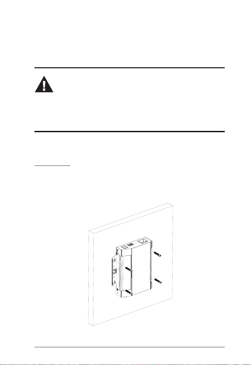
Wall Mount
To wall mount the Secure Device Server, doe the following:
Using 4 self-supplied screws, users can mount the unit onto a wall via the screw
holes at its sides, as shown below.
7
Secure Device Server User Manual
DIN Rail Mount
Use the DIN rail mount kit included to mount the Secure Device Server onto a
DIN rail, as instructed below:
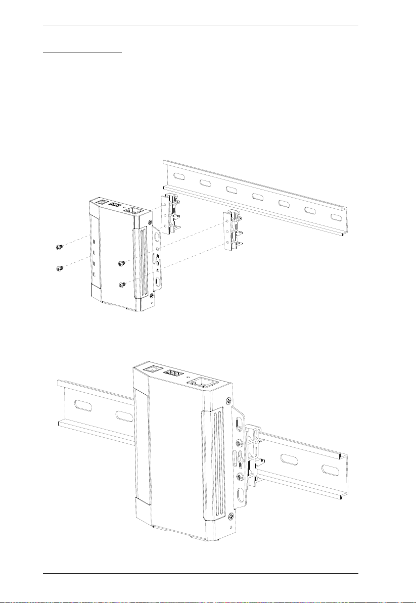
Parallel DIN Rail Mount
1. To mount the unit parallel to the DIN rail, attach 2 DIN rail mount brackets
onto the unit with the 4 screws provided, via its center screw holes.
2. Hang the unit onto the DIN rail.
8
Chapter 2. Hardware Setup
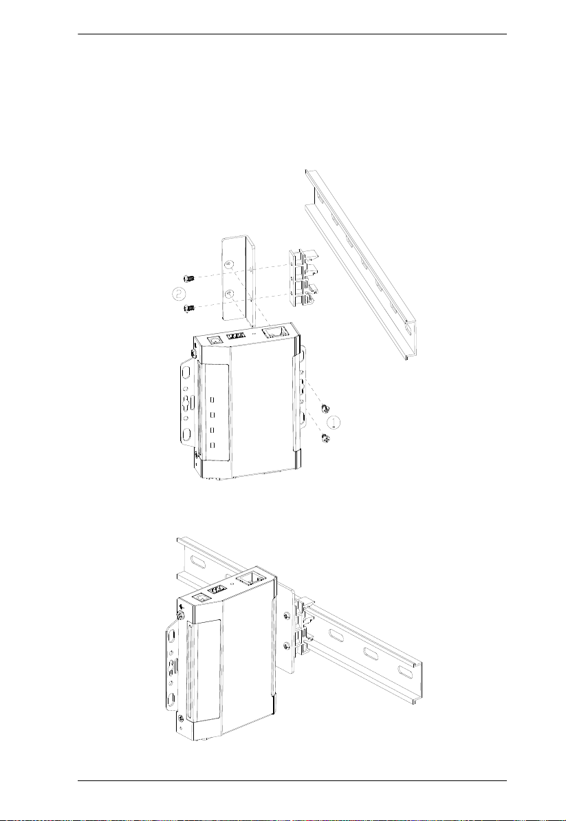
Perpendicular DIN Rail Mount
1. Attach the L-shape mounting bracket onto the unit with 2 M3x6 screws,
via its center screw holes at the side opposite to its grounding terminal.
2. Using 2 of the 4 screws enclosed, attach 1 DIN rail mount bracket onto the
side of the L-shape mounting bracket.
3. Hang the unit onto the DIN rail.
9
Secure Device Server User Manual
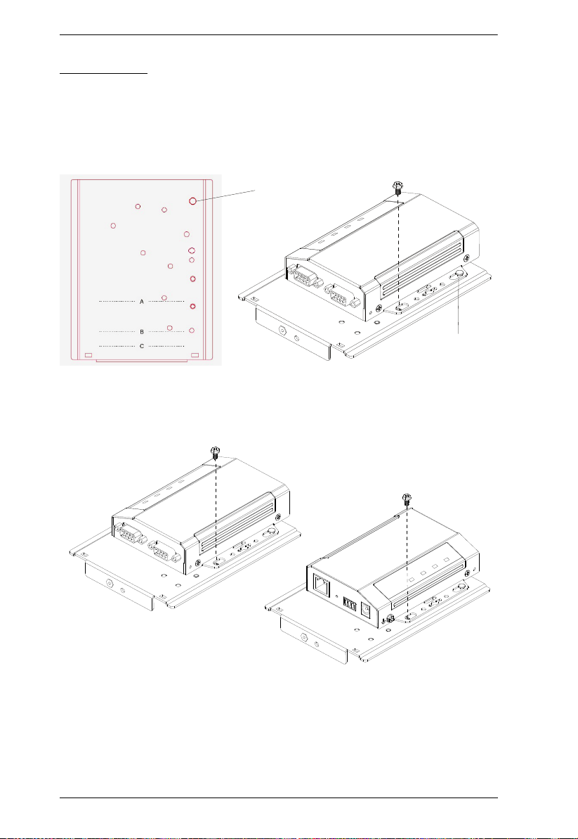
Mounting Plate
Protruded dot
Protruded dot
Rack Mount
The Rack Mount Kit (VE-RMK1U) is required for mounting the Secure
Device Server onto a rack, as instructed below:
1. Place the device onto the mounting plate while latching one of its rack ears
onto the plate’s protruded dot, as illustrated below.
2. Secure the device to the mounting plate using the hexagon head screw
supplied. Users can secure the Secure Device Server either with its serial
port(s) facing inward or outward.
10
Chapter 2. Hardware Setup
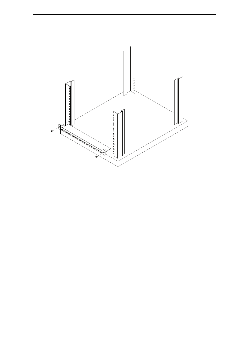
3. Position and align the holes on the VE-RMK1U frame with that of the
rack, and secure the frame onto the rack with 2 self-supplied screws, as
illustrated below.
11
Secure Device Server User Manual
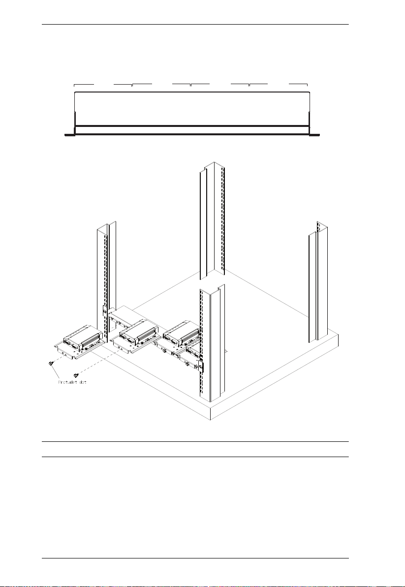
VE-RMK1U Frame
slot 1
slot 2
slot 3
slot 4
4. Align the device and mounting plate assembly to one of the slots on the
VE-RMK1U frame, and then secure the mounting plate to the frame with
the plastic captive screw provided.
Note: Up to 4 Secure Device Servers can be secured onto a VE-RMK1U frame.
12
Chapter 2. Hardware Setup
2
3
ST.343ST.343
Installation
To install the Secure Device Server, follow the steps below and refer to the
diagram on the following page (the number labels correspond to the installation
steps).
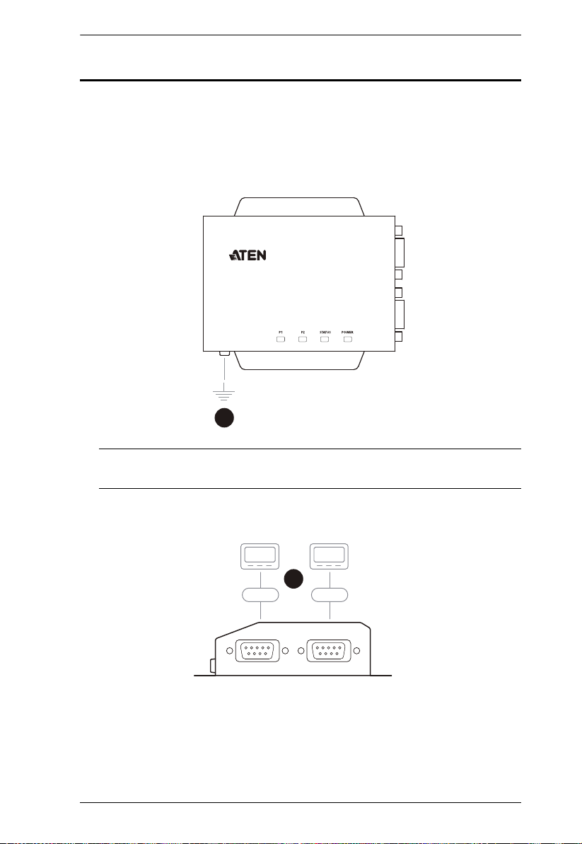
1. Use a grounding wire to ground the unit by connecting one end of the
grounding terminal and the other end to a suitable grounded object.
Note: Do not omit this step. Proper grounding helps prevent damage to the
unit from power surges and static electricity.
2. Connect the unit’s RS-232 serial port(s) to one or up to two serial
device(s).
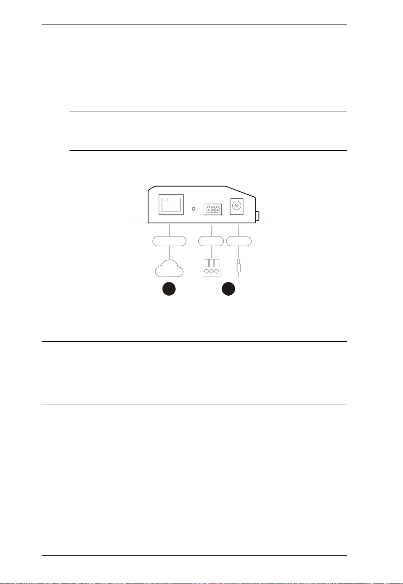
3. Connect the unit’s LAN port to the network using a Cat 5e/6 cable. For
SN3001P / SN3002P (PoE 802.3af compliant), users can simultaneously
supply power to the unit through a PoE switch and skip 4.
13
Secure Device Server User Manual
4 5
QpxfsQpxfsOfuxpsl
4. Connect the unit to power, thereby turning it on, by doing one, or both of
the following for power redundancy:
Plug the power adapter provided (not included for SN3001P /
SN3002P) into an AC power source, and plug its cable into the unit’s
power jack.
Note: The temperature tolerance of the power adapter is 0 – 40 °C. If
your environment temperature is 40 – 60 °C, you can only power
the device via the power terminal.
Connect DC + and - wires (DC 9 – 48 V) to the unit’s power terminal
with the terminal block provided.
5. After supplying power, wait for about 50 seconds for the Secure Device
Server to be ready and lights its status LED in constant green.
Note: When more than one power supply is connected, the additional power
connections maintain operation when the other is interrupted. For example, if
you have the device connected to power via both its power jack and power
terminal, the power terminal maintains operation when the power from the
power jack fails, and vice versa.
14
Chapter 2. Hardware Setup
Serial Port Pin Assignments
The pin assignments of Secure Device Server’s RS-232 serial ports are
provided below:
Pin
1 DCD
2RxD
3TxD
4DTR
5GND
6DSR
7RTS
8CTS
Configuration
RS-232
15

Secure Device Server User Manual
This Page Intentionally Left Blank
16
Chapter 3
Network Configuration and Login
IP Address Determination
Before you start, make sure the PC you’re using is within the same LAN as the
Secure Device Server.
There are two methods for determining / setting the IP address of your Secure
Device Server, one through the IP Installer Utility on a Windows PC, and one
just using a PC (only applicable to non-DHCP network), as described below:
IP Installer Utility
Using a Windows PC, users can search for Secure Device Server’s IP address
or assign an IP address to it, in a DHCP or non-DHCP network, with the IP
Installer Utility.
1. Download IP Installer zip file under the Support and Downloads tab from
the product web page.
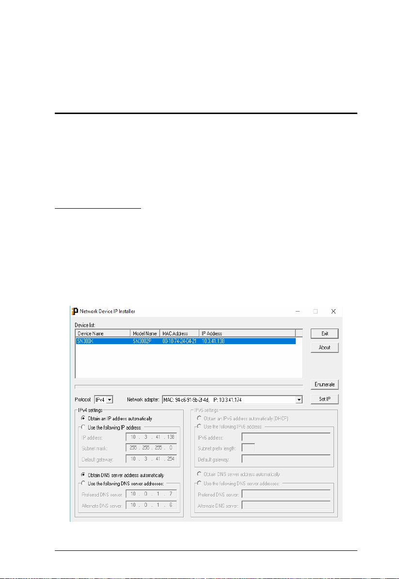
2. Extract and execute IPInstaller.exe. A dialog box similar to the one below
appears.
17

Secure Device Server User Manual
3. :Select the Secure Device Server in the Device List.
Note: 1. If the list is empty, or your device doesn't appear, double-check
that you have the correct network adapter selected and click
Enumerate to refresh the Device List.
2. If there is more than one device in the list, use the MAC address
to distinguish your device. The Secure Device Server’s MAC
address is located on its bottom panel.
4. To check the IP address of the Secure Device Server or set an IP address
for it, respectively select Obtain an IP address automatically or Use the
following IP address.
For setting an IP address, fill in the required IP address, subnet mask
and gateway information according to your network environment.
5. Click Set IP. The IP address of the Secure Device Server is displayed in
the Device List.
6. Click Exit to close the program.
Without IP Installer (non-DHCP only)
On a non-Windows system, under non-DHCP network, users can assign a static
IP address to the Secure Device Server, different from its default of
192.168.0.60, by following the steps below.
1. Set your PC’s IP address to 192.168.0.XXX, where XXX can be any
number except for 10.
2. Type the device’s default IP address — 192.168.0.60 — in your browser’s
URL location bar.
3. Log in with a valid username and password (see page 19).
4. On the Secure Device Server’s web interface, assign a fixed IP address for
it according to your network environment.
5. Save the settings and log out. After you log out, make sure to reset your
PC’s IP address to its original value.
18
 Loading...