

Page 1
Serial Console Server
SN0108CO / SN0116CO / SN0132CO / SN0148CO /
SN9108CO / SN9116CO / SN0108COD / SN0116COD /
SN0132COD / SN0148COD
User Manual
www.aten.com
Page 2
Serial Console Server User Manual
EMC Information
FEDERAL COMMUNICATIONS COMMISSION INTERFERENCE
STATEMENT: This equipment has been tested and found to comply with the
limits for a Class A digital device, pursuant to Part 15 of the FCC Rules. These
limits are designed to provide reasonable protection against harmful
interference when the equipment is operated in a commercial environment.
This equipment generates, uses, and can radiate radio frequency energy and, if
not installed and used in accordance with the instruction manual, may cause
harmful interference to radio communications. Operation of this equipment in
a residential area is likely to cause harmful interference in which case the user
will be required to correct the interference at his own expense.
This device complies with Part 15 of the FCC Rules. Operation is subject to the
following two conditions: (1) this device mat not cause harmful interference,
and (2) this device must accept any interference received, including
interference that may cause undesired operation.
FCC Caution: Any changes or modifications not expressly approved by the
party responsible for compliance could void the user's authority to operate this
equipment.
Warning: Operation of this equipment in a residential environment could
cause radio interference.
KCC Statement:
RoHS
This product is RoHS compliant.
ii
Page 3

Battery Safety Notice
There is a risk of explosion if the battery is replaced with an
incorrect type. Dispose of used batteries according to the
relevant instructions.
Batterie avis de sécurité
Il existe un risque d'explosion si la batterie est remplacée par
un incorrect tapez. Jeter les piles usagées selon la pertinente
instructions.
Serial Console Server User Manual
iii
Page 4

Serial Console Server User Manual
User Information
Online Registration
Be sure to register your product at our online support center:
International http://eservice.aten.com
Telephone Support
For telephone support, call this number:
International 886-2-8692-6959
China 86-400-810-0-810
Japan 81-3-5615-5811
Korea 82-2-467-6789
North America 1-888-999-ATEN ext 4988
1-949-428-1111
User Notice
All information, documentation, and specifications contained in this manual
are subject to change without prior notification by the manufacturer. The
manufacturer makes no representations or warranties, either expressed or
implied, with respect to the contents hereof and specifically disclaims any
warranties as to merchantability or fitness for any particular purpose. Any of
the manufacturer's software described in this manual is sold or licensed as is.
Should the programs prove defective following their purchase, the buyer (and
not the manufacturer, its distributor, or its dealer), assumes the entire cost of all
necessary servicing, repair and any incidental or consequential damages
resulting from any defect in the software.
The manufacturer of this system is not responsible for any radio and/or TV
interference caused by unauthorized modifications to this device. It is the
responsibility of the user to correct such interference.
The manufacturer is not responsible for any damage incurred in the operation
of this system if the correct operational voltage setting was not selected prior
to operation. PLEASE VERIFY THAT THE VOLTAGE SETTING IS
CORRECT BEFORE USE.
iv
Page 5

Serial Console Server User Manual
Package Contents
The Serial Console Server package consists of:
SN0108CO / SN0116CO
1 SN0108CO / SN0116CO Serial Console Server
1 Laptop USB Console Cable
2 Power Cords
1 Mounting Kit
2 Lok-U-Plugs
1 Lok-U-Plug Installation Tool
1 Foot Pad Set (4 pcs.)
1 User Instructions*
SN0108COD / SN0116COD
1 SN0108COD / SN0116COD Serial Console Server
1 Laptop USB Console Cable
1 Mounting Kit
1 Foot Pad Set (4 pcs.)
1 User Instructions*
SN0132CO / SN0148CO
1 SN0132CO / SN0148CO Serial Console Server
1 Laptop USB Console Cable
2 Power Cords
1 Mounting Kit
1 Foot Pad Set (4 pcs.)
1 User Instructions*
v
Page 6

Serial Console Server User Manual
Copyright © 2018 ATEN® International Co., Ltd.
Manual Date: 2019-01-24
Altusen and the Altusen logo are registered trademarks of ATEN International Co., Ltd. All rights reserved.
All other brand names and trademarks are the registered property of their respective owners.
SN0132COD / SN0148COD
1 SN0132COD / SN0148COD Serial Console Server
1 Laptop USB Console Cable
1 Mounting Kit
1 Foot Pad Set (4 pcs.)
1 User Instructions*
SN9108CO / SN9116CO
1 SN9108CO / SN9116CO Serial Console Server
1Power Cord
1 Mounting Kit
1 Lok-U-Plug
1 Lok-U-Plug Installation Tool
1 Foot Pad Set (4 pcs.)
1 User Instructions*
*Features may have been added since this manual was published. Please visit
our website to download the most up-to-date version of the manual
Check to make sure that all of the components are present and in good order.
If anything is missing, or was damaged in shipping, contact your dealer. Read
this manual thoroughly and follow the installation and operation procedures
carefully to prevent any damage to the Serial Console Server or to any other
devices on the installation.
vi
.
Page 7

Serial Console Server User Manual
Contents
EMC Information . . . . . . . . . . . . . . . . . . . . . . . . . . . . . . . . . . . . . . . . . . . . ii
Battery Safety Notice. . . . . . . . . . . . . . . . . . . . . . . . . . . . . . . . . . . . . . .iii
Batterie avis de sécurité . . . . . . . . . . . . . . . . . . . . . . . . . . . . . . . . . . . .iii
User Information . . . . . . . . . . . . . . . . . . . . . . . . . . . . . . . . . . . . . . . . . . . . iv
Online Registration . . . . . . . . . . . . . . . . . . . . . . . . . . . . . . . . . . . . . . . iv
Telephone Support . . . . . . . . . . . . . . . . . . . . . . . . . . . . . . . . . . . . . . . iv
User Notice . . . . . . . . . . . . . . . . . . . . . . . . . . . . . . . . . . . . . . . . . . . . . iv
Package Contents . . . . . . . . . . . . . . . . . . . . . . . . . . . . . . . . . . . . . . . . . . . v
SN0108CO / SN0116CO. . . . . . . . . . . . . . . . . . . . . . . . . . . . . . . . . . . . v
SN0108COD / SN0116COD . . . . . . . . . . . . . . . . . . . . . . . . . . . . . . . . v
SN0132CO / SN0148CO . . . . . . . . . . . . . . . . . . . . . . . . . . . . . . . . . . . v
SN0132COD / SN0148COD . . . . . . . . . . . . . . . . . . . . . . . . . . . . . . . vi
SN9108CO / SN9116CO . . . . . . . . . . . . . . . . . . . . . . . . . . . . . . . . . . vi
Contents . . . . . . . . . . . . . . . . . . . . . . . . . . . . . . . . . . . . . . . . . . . . . . . . . . vii
About This Manual . . . . . . . . . . . . . . . . . . . . . . . . . . . . . . . . . . . . . . . . . . xii
Overview . . . . . . . . . . . . . . . . . . . . . . . . . . . . . . . . . . . . . . . . . . . . . . . xii
Conventions . . . . . . . . . . . . . . . . . . . . . . . . . . . . . . . . . . . . . . . . . . . .xiii
Terminology . . . . . . . . . . . . . . . . . . . . . . . . . . . . . . . . . . . . . . . . . . . .xiv
Chapter 1.
Overview . . . . . . . . . . . . . . . . . . . . . . . . . . . . . . . . . . . . . . . . . . . . . . . . . . . 1
Features . . . . . . . . . . . . . . . . . . . . . . . . . . . . . . . . . . . . . . . . . . . . . . . . . . . 3
Requirements . . . . . . . . . . . . . . . . . . . . . . . . . . . . . . . . . . . . . . . . . . . . . . .6
Components . . . . . . . . . . . . . . . . . . . . . . . . . . . . . . . . . . . . . . . . . . . . . . . .9
Introduction
System Accessibility and Availability. . . . . . . . . . . . . . . . . . . . . . . . . . . 3
Serial Console Management. . . . . . . . . . . . . . . . . . . . . . . . . . . . . . . . . 3
Security . . . . . . . . . . . . . . . . . . . . . . . . . . . . . . . . . . . . . . . . . . . . . . . . .4
System Management . . . . . . . . . . . . . . . . . . . . . . . . . . . . . . . . . . . . . .4
Serial Device Management . . . . . . . . . . . . . . . . . . . . . . . . . . . . . . . . . .5
Language . . . . . . . . . . . . . . . . . . . . . . . . . . . . . . . . . . . . . . . . . . . . . . .5
DTE/DCE Auto-Sensing . . . . . . . . . . . . . . . . . . . . . . . . . . . . . . . . . . . .7
Browsers . . . . . . . . . . . . . . . . . . . . . . . . . . . . . . . . . . . . . . . . . . . . . . .8
SN0108CO / SN0108COD Front View . . . . . . . . . . . . . . . . . . . . . . . . . 9
SN0116CO / SN0116COD Front View . . . . . . . . . . . . . . . . . . . . . . . . . 9
SN0132CO / SN0132COD Front View . . . . . . . . . . . . . . . . . . . . . . . . 11
SN0148CO / SN0148COD Front View . . . . . . . . . . . . . . . . . . . . . . . . 11
SN9108CO Front View . . . . . . . . . . . . . . . . . . . . . . . . . . . . . . . . . . . .13
SN9116CO Front View . . . . . . . . . . . . . . . . . . . . . . . . . . . . . . . . . . . .13
SN0108CO Rear View . . . . . . . . . . . . . . . . . . . . . . . . . . . . . . . . . . . .15
SN0116CO Rear View . . . . . . . . . . . . . . . . . . . . . . . . . . . . . . . . . . . .15
SN0108COD Rear View (DC Power) . . . . . . . . . . . . . . . . . . . . . . . . . 16
SN0116COD Rear View (DC Power) . . . . . . . . . . . . . . . . . . . . . . . . . 16
SN0132CO Rear View . . . . . . . . . . . . . . . . . . . . . . . . . . . . . . . . . . . .17
SN0148CO Rear View . . . . . . . . . . . . . . . . . . . . . . . . . . . . . . . . . . . .17
vii
Page 8

Serial Console Server User Manual
SN0132COD Rear View (DC Power) . . . . . . . . . . . . . . . . . . . . . . . . . 18
SN0148COD Rear View (DC Power) . . . . . . . . . . . . . . . . . . . . . . . . . 18
SN9108CO Rear View . . . . . . . . . . . . . . . . . . . . . . . . . . . . . . . . . . . . 19
SN9116CO Rear View . . . . . . . . . . . . . . . . . . . . . . . . . . . . . . . . . . . . 19
Chapter 2.
Before You Begin . . . . . . . . . . . . . . . . . . . . . . . . . . . . . . . . . . . . . . . . . . . 21
Stacking and Rack Mounting . . . . . . . . . . . . . . . . . . . . . . . . . . . . . . . . . . 21
Serial Console Server Installation . . . . . . . . . . . . . . . . . . . . . . . . . . . . . . 27
Chapter 3.
Overview. . . . . . . . . . . . . . . . . . . . . . . . . . . . . . . . . . . . . . . . . . . . . . . . . . 33
First Time Setup . . . . . . . . . . . . . . . . . . . . . . . . . . . . . . . . . . . . . . . . . . . . 33
Setup . . . . . . . . . . . . . . . . . . . . . . . . . . . . . . . . . . . . . . . . . . . . . . . . . . . . 38
Chapter 4.
Overview . . . . . . . . . . . . . . . . . . . . . . . . . . . . . . . . . . . . . . . . . . . . . . . . . 41
Access . . . . . . . . . . . . . . . . . . . . . . . . . . . . . . . . . . . . . . . . . . . . . . . . . . . 41
Local Console Operation . . . . . . . . . . . . . . . . . . . . . . . . . . . . . . . . . . . . . 42
Remote Operation . . . . . . . . . . . . . . . . . . . . . . . . . . . . . . . . . . . . . . . . . . 43
Hardware Setup
Stacking . . . . . . . . . . . . . . . . . . . . . . . . . . . . . . . . . . . . . . . . . . . . . . . 21
Rack Mounting . . . . . . . . . . . . . . . . . . . . . . . . . . . . . . . . . . . . . . . . . . 23
Rack Mounting - Front. . . . . . . . . . . . . . . . . . . . . . . . . . . . . . . . . . 23
Rack Mounting - Rear . . . . . . . . . . . . . . . . . . . . . . . . . . . . . . . . . . 25
SN0108CO / SN0116CO / SN0132CO / SN0148CO Installation . . . . 27
SN9108CO / SN9116CO Installation . . . . . . . . . . . . . . . . . . . . . . . . . 30
Super Administrator Setup
Local Login . . . . . . . . . . . . . . . . . . . . . . . . . . . . . . . . . . . . . . . . . . . . . 33
Laptop USB Console (LUC) Login - SNViewerUSB . . . . . . . . . . . 34
Console Login - HyperTerminal. . . . . . . . . . . . . . . . . . . . . . . . . . . 34
Local Console Main Menu. . . . . . . . . . . . . . . . . . . . . . . . . . . . . . . 35
Remote Login . . . . . . . . . . . . . . . . . . . . . . . . . . . . . . . . . . . . . . . . . . . 36
Telnet Login. . . . . . . . . . . . . . . . . . . . . . . . . . . . . . . . . . . . . . . . . . 36
PuTTY Login . . . . . . . . . . . . . . . . . . . . . . . . . . . . . . . . . . . . . . . . . 36
Browser Login . . . . . . . . . . . . . . . . . . . . . . . . . . . . . . . . . . . . . . . 37
Network Setup. . . . . . . . . . . . . . . . . . . . . . . . . . . . . . . . . . . . . . . . . . . 38
Changing the Super Administrator Login . . . . . . . . . . . . . . . . . . . . . . 39
The User Interface
Web Browser Login. . . . . . . . . . . . . . . . . . . . . . . . . . . . . . . . . . . . . . . 43
The Web Browser Main Page . . . . . . . . . . . . . . . . . . . . . . . . . . . . . . 44
Page Components . . . . . . . . . . . . . . . . . . . . . . . . . . . . . . . . . . . . . . . 44
The Tab Bar . . . . . . . . . . . . . . . . . . . . . . . . . . . . . . . . . . . . . . . . . . . . 46
SNViewer . . . . . . . . . . . . . . . . . . . . . . . . . . . . . . . . . . . . . . . . . . . . . . 47
SNViewer Control Panel . . . . . . . . . . . . . . . . . . . . . . . . . . . . . . . . 47
Control Panel Functions . . . . . . . . . . . . . . . . . . . . . . . . . . . . . . . . . . . 48
Data Import . . . . . . . . . . . . . . . . . . . . . . . . . . . . . . . . . . . . . . . . . . . . 49
Encode . . . . . . . . . . . . . . . . . . . . . . . . . . . . . . . . . . . . . . . . . . . . . . . . 50
The Message Board . . . . . . . . . . . . . . . . . . . . . . . . . . . . . . . . . . . . . . 50
Message Display Panel. . . . . . . . . . . . . . . . . . . . . . . . . . . . . . . . . 50
viii
Page 9

Serial Console Server User Manual
Compose Panel . . . . . . . . . . . . . . . . . . . . . . . . . . . . . . . . . . . . . . .50
User List Panel . . . . . . . . . . . . . . . . . . . . . . . . . . . . . . . . . . . . . . .50
Macros . . . . . . . . . . . . . . . . . . . . . . . . . . . . . . . . . . . . . . . . . . . . . . . .51
Terminal Settings . . . . . . . . . . . . . . . . . . . . . . . . . . . . . . . . . . . . . . . .52
Terminal Application . . . . . . . . . . . . . . . . . . . . . . . . . . . . . . . . . . . . . . 54
Telnet Menu-Driven Text UI. . . . . . . . . . . . . . . . . . . . . . . . . . . . . .54
Chapter 5.
Overview . . . . . . . . . . . . . . . . . . . . . . . . . . . . . . . . . . . . . . . . . . . . . . . . . . 55
Operating Mode . . . . . . . . . . . . . . . . . . . . . . . . . . . . . . . . . . . . . . . . . . . .56
Chapter 6.
Overview . . . . . . . . . . . . . . . . . . . . . . . . . . . . . . . . . . . . . . . . . . . . . . . . . . 59
The Sidebar . . . . . . . . . . . . . . . . . . . . . . . . . . . . . . . . . . . . . . . . . . . . . . .60
Connections . . . . . . . . . . . . . . . . . . . . . . . . . . . . . . . . . . . . . . . . . . . . . . .62
Favorites . . . . . . . . . . . . . . . . . . . . . . . . . . . . . . . . . . . . . . . . . . . . . . . . .65
History. . . . . . . . . . . . . . . . . . . . . . . . . . . . . . . . . . . . . . . . . . . . . . . . . . . . 65
Preferences. . . . . . . . . . . . . . . . . . . . . . . . . . . . . . . . . . . . . . . . . . . . . . . .66
Sessions . . . . . . . . . . . . . . . . . . . . . . . . . . . . . . . . . . . . . . . . . . . . . . . . . .67
Access. . . . . . . . . . . . . . . . . . . . . . . . . . . . . . . . . . . . . . . . . . . . . . . . . . . . 68
Properties . . . . . . . . . . . . . . . . . . . . . . . . . . . . . . . . . . . . . . . . . . . . . . . . .70
Port Operating Modes
Console Management . . . . . . . . . . . . . . . . . . . . . . . . . . . . . . . . . . . . .56
Real COM Port . . . . . . . . . . . . . . . . . . . . . . . . . . . . . . . . . . . . . . . . . . 56
TCP Server / TCP Client (Serial Tunnel). . . . . . . . . . . . . . . . . . . . . . .56
TCP Server (RAW TCP) . . . . . . . . . . . . . . . . . . . . . . . . . . . . . . . .56
TCP Client . . . . . . . . . . . . . . . . . . . . . . . . . . . . . . . . . . . . . . . . . . .57
UDP Mode. . . . . . . . . . . . . . . . . . . . . . . . . . . . . . . . . . . . . . . . . . . . . .57
Virtual Modem . . . . . . . . . . . . . . . . . . . . . . . . . . . . . . . . . . . . . . . . . . .57
Console Management Direct. . . . . . . . . . . . . . . . . . . . . . . . . . . . . . . .58
Disabled . . . . . . . . . . . . . . . . . . . . . . . . . . . . . . . . . . . . . . . . . . . . . . .58
Port Access
The Sidebar Tree Structure. . . . . . . . . . . . . . . . . . . . . . . . . . . . . . . . .60
Filter . . . . . . . . . . . . . . . . . . . . . . . . . . . . . . . . . . . . . . . . . . . . . . . . . .61
Telnet/SSH . . . . . . . . . . . . . . . . . . . . . . . . . . . . . . . . . . . . . . . . . . . . . 63
Port Attributes . . . . . . . . . . . . . . . . . . . . . . . . . . . . . . . . . . . . . . . . . . .63
Save & Copy . . . . . . . . . . . . . . . . . . . . . . . . . . . . . . . . . . . . . . . . . 71
Port Buffering . . . . . . . . . . . . . . . . . . . . . . . . . . . . . . . . . . . . . . . . . . .72
Operating Mode . . . . . . . . . . . . . . . . . . . . . . . . . . . . . . . . . . . . . . . . .73
Alert Strings . . . . . . . . . . . . . . . . . . . . . . . . . . . . . . . . . . . . . . . . . .74
Command Filters . . . . . . . . . . . . . . . . . . . . . . . . . . . . . . . . . . . . .75
Chapter 7.
Overview . . . . . . . . . . . . . . . . . . . . . . . . . . . . . . . . . . . . . . . . . . . . . . . . . . 81
Users . . . . . . . . . . . . . . . . . . . . . . . . . . . . . . . . . . . . . . . . . . . . . . . . . . . .82
Groups . . . . . . . . . . . . . . . . . . . . . . . . . . . . . . . . . . . . . . . . . . . . . . . . . . .86
User Management
Adding Users . . . . . . . . . . . . . . . . . . . . . . . . . . . . . . . . . . . . . . . . . . . 82
Modifying User Accounts . . . . . . . . . . . . . . . . . . . . . . . . . . . . . . . . . .85
Deleting User Accounts . . . . . . . . . . . . . . . . . . . . . . . . . . . . . . . . . . . 85
ix
Page 10

Serial Console Server User Manual
Creating Groups . . . . . . . . . . . . . . . . . . . . . . . . . . . . . . . . . . . . . . . . . 86
Modifying Groups . . . . . . . . . . . . . . . . . . . . . . . . . . . . . . . . . . . . . . . . 88
Deleting Groups . . . . . . . . . . . . . . . . . . . . . . . . . . . . . . . . . . . . . . . . . 88
Users and Groups . . . . . . . . . . . . . . . . . . . . . . . . . . . . . . . . . . . . . . . . . . 89
Assigning Users to a Group From the User’s Notebook. . . . . . . . . . . 89
Removing Users From a Group From the User’s Notebook . . . . . . . 91
Assigning Users to a Group From the Group’s Notebook . . . . . . . . . 92
Removing Users From a Group From the Group’s Notebook . . . . . . 93
Device Assignment . . . . . . . . . . . . . . . . . . . . . . . . . . . . . . . . . . . . . . . . . 94
Assigning Device Permissions under User Settings. . . . . . . . . . . . . . 94
Assigning Device Permissions under Group Settings . . . . . . . . . . . . 96
Chapter 8.
Devices . . . . . . . . . . . . . . . . . . . . . . . . . . . . . . . . . . . . . . . . . . . . . . . . . . . 97
Device Management
General . . . . . . . . . . . . . . . . . . . . . . . . . . . . . . . . . . . . . . . . . . . . . 97
Mounted Devices. . . . . . . . . . . . . . . . . . . . . . . . . . . . . . . . . . . . . . 98
Network . . . . . . . . . . . . . . . . . . . . . . . . . . . . . . . . . . . . . . . . . . . . . . 100
IP Installer . . . . . . . . . . . . . . . . . . . . . . . . . . . . . . . . . . . . . . . . . 101
Service Ports. . . . . . . . . . . . . . . . . . . . . . . . . . . . . . . . . . . . . . . . 101
Network Configuration . . . . . . . . . . . . . . . . . . . . . . . . . . . . . . . . 102
ANMS . . . . . . . . . . . . . . . . . . . . . . . . . . . . . . . . . . . . . . . . . . . . . . . . 105
Event Destination . . . . . . . . . . . . . . . . . . . . . . . . . . . . . . . . . . . . 105
Authentication and Authorization . . . . . . . . . . . . . . . . . . . . . . . . 109
CC Management Settings . . . . . . . . . . . . . . . . . . . . . . . . . . . . . 113
OOBC . . . . . . . . . . . . . . . . . . . . . . . . . . . . . . . . . . . . . . . . . . . . . . . . 114
Enable Dial Back . . . . . . . . . . . . . . . . . . . . . . . . . . . . . . . . . . . . 117
Enable Dial Out . . . . . . . . . . . . . . . . . . . . . . . . . . . . . . . . . . . . . . 117
Security . . . . . . . . . . . . . . . . . . . . . . . . . . . . . . . . . . . . . . . . . . . . . . 119
Login Failures . . . . . . . . . . . . . . . . . . . . . . . . . . . . . . . . . . . . . . . 119
Security Level . . . . . . . . . . . . . . . . . . . . . . . . . . . . . . . . . . . . . . . 120
Working Mode . . . . . . . . . . . . . . . . . . . . . . . . . . . . . . . . . . . . . . . 120
IP/MAC Filter . . . . . . . . . . . . . . . . . . . . . . . . . . . . . . . . . . . . . . . . 121
Account Policy . . . . . . . . . . . . . . . . . . . . . . . . . . . . . . . . . . . . . . 123
Association . . . . . . . . . . . . . . . . . . . . . . . . . . . . . . . . . . . . . . . . . . . . 124
Date/Time . . . . . . . . . . . . . . . . . . . . . . . . . . . . . . . . . . . . . . . . . . . . . 125
Current System Time . . . . . . . . . . . . . . . . . . . . . . . . . . . . . . . . . 125
New System Time . . . . . . . . . . . . . . . . . . . . . . . . . . . . . . . . . . . 126
Time Zone . . . . . . . . . . . . . . . . . . . . . . . . . . . . . . . . . . . . . . . . . . 126
Chapter 9.
Overview. . . . . . . . . . . . . . . . . . . . . . . . . . . . . . . . . . . . . . . . . . . . . . . . . 127
System Log. . . . . . . . . . . . . . . . . . . . . . . . . . . . . . . . . . . . . . . . . . . . . . . 127
Log Notification Settings . . . . . . . . . . . . . . . . . . . . . . . . . . . . . . . . . . . . 130
Chapter 10.
Overview. . . . . . . . . . . . . . . . . . . . . . . . . . . . . . . . . . . . . . . . . . . . . . . . . 131
x
Log
Filter . . . . . . . . . . . . . . . . . . . . . . . . . . . . . . . . . . . . . . . . . . . . . . . . . 128
Maintenance
Page 11

Serial Console Server User Manual
Backup / Restore. . . . . . . . . . . . . . . . . . . . . . . . . . . . . . . . . . . . . . . . . . . 131
Backup . . . . . . . . . . . . . . . . . . . . . . . . . . . . . . . . . . . . . . . . . . . . . . .132
Restore . . . . . . . . . . . . . . . . . . . . . . . . . . . . . . . . . . . . . . . . . . . . . . .132
Firmware Upgrade . . . . . . . . . . . . . . . . . . . . . . . . . . . . . . . . . . . . . . . . .133
Certificates . . . . . . . . . . . . . . . . . . . . . . . . . . . . . . . . . . . . . . . . . . . . . . .134
Private Certificate . . . . . . . . . . . . . . . . . . . . . . . . . . . . . . . . . . . . 134
Certificate Signing Request . . . . . . . . . . . . . . . . . . . . . . . . . . . .136
Appendix
Safety Instructions. . . . . . . . . . . . . . . . . . . . . . . . . . . . . . . . . . . . . . . . . .139
General . . . . . . . . . . . . . . . . . . . . . . . . . . . . . . . . . . . . . . . . . . . . . . .139
DC Power . . . . . . . . . . . . . . . . . . . . . . . . . . . . . . . . . . . . . . . . . . . . .142
Rack Mounting . . . . . . . . . . . . . . . . . . . . . . . . . . . . . . . . . . . . . . . . .143
Technical Support . . . . . . . . . . . . . . . . . . . . . . . . . . . . . . . . . . . . . . . . . 144
International . . . . . . . . . . . . . . . . . . . . . . . . . . . . . . . . . . . . . . . . . . .144
North America . . . . . . . . . . . . . . . . . . . . . . . . . . . . . . . . . . . . . . . . .144
Specifications . . . . . . . . . . . . . . . . . . . . . . . . . . . . . . . . . . . . . . . . . . . . .145
SN0108CO / SN0116CO . . . . . . . . . . . . . . . . . . . . . . . . . . . . . . . . .145
SN0108COD / SN0116COD . . . . . . . . . . . . . . . . . . . . . . . . . . . . . .146
SN0132CO / SN0148CO . . . . . . . . . . . . . . . . . . . . . . . . . . . . . . . . .147
SN0132COD / SN0148COD . . . . . . . . . . . . . . . . . . . . . . . . . . . . . .148
SN9108CO / SN9116CO . . . . . . . . . . . . . . . . . . . . . . . . . . . . . . . . .149
IP Address Determination . . . . . . . . . . . . . . . . . . . . . . . . . . . . . . . . . . .150
The Local Console . . . . . . . . . . . . . . . . . . . . . . . . . . . . . . . . . . . . . .150
IP Installer . . . . . . . . . . . . . . . . . . . . . . . . . . . . . . . . . . . . . . . . . . . . .150
Browser . . . . . . . . . . . . . . . . . . . . . . . . . . . . . . . . . . . . . . . . . . . . . .151
IPv6 152
Link Local IPv6 Address . . . . . . . . . . . . . . . . . . . . . . . . . . . . . . . . . . 152
IPv6 Stateless Autoconfiguration . . . . . . . . . . . . . . . . . . . . . . . . . . .153
Virtual Modem Details . . . . . . . . . . . . . . . . . . . . . . . . . . . . . . . . . . . . . .154
AT Command Set Support . . . . . . . . . . . . . . . . . . . . . . . . . . . . . . . .154
Port Forwarding . . . . . . . . . . . . . . . . . . . . . . . . . . . . . . . . . . . . . . . . . . .156
Clear Login Information . . . . . . . . . . . . . . . . . . . . . . . . . . . . . . . . . . . . .157
Pin Assignment . . . . . . . . . . . . . . . . . . . . . . . . . . . . . . . . . . . . . . . . . . . 158
DCE Mode Pin Assignment . . . . . . . . . . . . . . . . . . . . . . . . . . . . .158
DTE Mode Pin Assignment . . . . . . . . . . . . . . . . . . . . . . . . . . . . .158
DB-9/DB-25 Interface . . . . . . . . . . . . . . . . . . . . . . . . . . . . . . . . . . . .159
DB-9. . . . . . . . . . . . . . . . . . . . . . . . . . . . . . . . . . . . . . . . . . . . . . .159
DB-25. . . . . . . . . . . . . . . . . . . . . . . . . . . . . . . . . . . . . . . . . . . . . .159
Limited Warranty. . . . . . . . . . . . . . . . . . . . . . . . . . . . . . . . . . . . . . . . . . .160
xi
Page 12

Serial Console Server User Manual
About This Manual
This User Manual is provided to help you get the most from your Serial
Console Server system. It covers all aspects of installation, configuration and
operation. An overview of the information found in the manual is provided
below.
Overview
Chapter 1, Introduction, introduces you to the Serial Console Server. Its
purpose, features and benefits are presented, and its front and back panel
components are described.
Chapter 2, Hardware Setup, provides step-by-step instructions for setting
up your installation, and explains some basic operation procedures.
Chapter 3, Super Administrator Setup, explains the procedures that the
super administrator employs to set up the Serial Console Server network
environment, and change the default username and password.
Chapter 4, The User Interface, describes the layout and explains the
components of the Serial Console Server user interface. Describes how to log
in to the Serial Console Server with each of the available access methods: from
a local console, an Internet browser, and Windows application (AP) programs.
Chapter 5, Port Operating Modes, describes the port operating modes,
including Console Management and Console Management Direct modes for
device control; and Real COM Port, Virtual Modem, TCP Server, TCP Client,
and UDP Mode for Serial-to-Ethernet connectivity and applications that
require COM ports, serial tunneling, or where TCP/UDP Socket functionality
is needed.
Chapter 6, Port Access, describes the Port Access page and how to
configure the options it provides regarding port and power outlet manipulation.
Chapter 7, User Management, shows super administrators and
administrators how to create, modify, and delete users and groups, and assign
attributes to them.
Chapter 8, Device Management, shows super administrators how to
configure and control overall Serial Console Server operations.
Chapter 9, Log, explains how to install and configure the Log Server.
Chapter 10, Maintenance, explains how to backup, restore, and upgrade the
Serial Console Server and its firmware, as well as providing information about
private certificates.
xii
Page 13

Serial Console Server User Manual
An Appendix, at the end of the manual provides technical and
troubleshooting information.
Conventions
This manual uses the following conventions:
Monospaced Indicates text that you should key in.
[ ] Indicates keys you should press. For example, [Enter] means
1. Numbered lists represent procedures with sequential steps.
♦ Bullet lists provide information, but do not involve sequential
→ Indicates selecting the option (on a menu or dialog box, for
to press the Enter key. If keys need to be chorded, they appear
together in the same bracket with a plus sign between them:
[Ctrl+Alt].
steps.
→
example), that comes next. For example, Start
to open the Start menu, and then select Run.
Indicates critical information.
Run means
xiii
Page 14

Serial Console Server User Manual
Terminology
Throughout the manual we make reference to the terms Local and Remote in
regard to the operators and equipment deployed in a Serial Console Server
installation. Depending on the point of view, users and servers can be
considered Local under some circumstances, and Remote under others:
Serial Console Server’s Point of View
Remote users – We refer to a user as a Remote user when we think of
him as someone who logs into the Serial Console Server over the net
from a location that is remote from the Serial Console Server.
Local Console – a computer connected directly to the Serial Console
Server by a physical connection.
Servers, Serial Device, or Port Device – any device attached to the
Serial Console Server’s ports via cable.
User’s Point of View
Local client users – We refer to a user as a Local user when we think of
him as sitting at his computer performing operations on the devices
connected to the Serial Console Server that is remote from him.
When we describe the overall system architecture we are usually speaking
from the Serial Console Server’s point of view – in which case the users are
considered remote. When we speak about operations users perform via the
browser, viewers, and AP programs over the net, we are usually speaking from
the user’s point of view – in which case the Serial Console Server and the
devices connected to it are considered remote.
International http://www.aten.com
North America http://www.aten.com/us/en/
xiv
Page 15

Chapter 1
Introduction
Overview
The SN01xxCO and SN91xxCO Series features Cisco pin-outs and autosensing DTE/DCE function, providing a direct connection to Cisco network
switches (and other compatible devices) without rollover cables for even more
time-saving IT infrastructure deployment. In addition, the SN01xxCO and
SN91xxCO models support online detection of connected serial devices
(including terminal blocks) for device status monitoring. A notification email
alert will be sent to the administrator when connected devices are offline.
With dual Ethernet ports and power supplies, the SN01xxCO supports power
redundancy as well as failover, or dual IP addresses access, ensuring 24/7
availability of access to serial devices. The SN01xxCO Series also offers dual
DC (see Note) options for more flexible implementation.
Note: Available with DC power at customer’s request (SN0108COD /
SN0116COD / SN0132COD / SN0148COD).
Available in 8-, 16-, 32- and 48-port models, the serial console servers offer
both in-band and out-of-band (OOB) remote serial console access to servers
and network devices via a direct Telnet/SSH client and Java viewer. The OOB
management enables IT administrators to manage network devices (e.g. router,
switch, UPS) in server rooms using management networks that are separated
from the main/production networks. Where access difficulty occurs in the
production network, the administrators can still access them via the console
server. The serial console servers offer out-of-band access methods such as
direct console connection from a local computer, USB console connection
from a laptop, PSTN connection via modem, or hybrid network connection via
the dual LAN ports (one connected to the production network and the other
connected to the management network).
Implemented with various security technologies such as TLS 1.2 data
encryption, RSA 2048-bit certificates, configurable user permissions for port
access and control, local/remote/third-party authentication and authorization,
IP/MAC address filter, and FIPS 140-2 certified cryptography, the SN01xxCO
and SN91xxCO serial console servers assure administrators the security for
easy and high-level access. For instance, access rights and privileges can be
applied to 8/16/32/48 serial ports individually. Data encryption is provided to
1
Page 16

Serial Console Server User Manual
ensure that information and control are always protected. Logging and alerting
of system events help to quickly resolve issues and mitigate risks. While
secured by the above examples, the consolidated password authentication
simplifies management.
The SN01xxCO and SN91xxCO Series are used to connect serial devices to an
Ethernet network to allow access and control of demanding applications that
manage industrial control, data acquisition, environment monitoring, remote
facility operations and equipment management. Multiple operational modes
are available to administrators including Console Management, Console
Management Direct, Real Com Port, TCP Server/Client, UDP Server/Client,
and Virtual Modem. Furthermore, the SN01xxCO Series works in tandem with
ATEN’s PDU (see Note) remote power management systems. Both can be
utilized through ATEN’s CC2000 software to provide centralized serial device
access and integrated power management.
Note: PON port reserved for PG Series PDU.
With their comprehensive features, the SN01xxCO and SN91xxCO Series help
to maximize IT productivity, increase scalability, as well as reduce installation
and operational costs with easy and secure remote management of serial
devices. The serial console servers save you time and money by allowing
administrators to manage their data centers from practically anywhere –
minimizing travel and MTTR (Mean Time to Repair) costs, ensuring the
highest availability for data center services.
2
Page 17

Chapter 1. Introduction
Features
System Accessibility and Availability
Secure in-band and out-of-band remote serial console access
Browser access with an intuitive GUI
Terminal-based access with a menu-driven UI
Modem dial-in/dial-back/dial-out access
Front USB ports for storage or USB-based PC cards*
Laptop USB Console (LUC) port for local console access via laptop*
Dual Ethernet ports allow fail control or dual IP address access*
Dual power supply*
Note: SN01xxCO only.
Serial Console Management
Auto-sensing DTE/DCE feature supports a direct connection to Cisco
network switches (and other compatible devices) without rollover cables
for more convenient IT infrastructure deployment
Online/Offline detection of connected serial devices (including terminal
blocks) – automatically send event notifications when the devices are
offline for device status monitoring
Convenient and simple serial device access via selectable Telnet/SSH and
third-party clients such as PuTTY
Easy port access via selectable ActiveX or Java serial viewer
Comprehensive viewer functions – copy/paste, logging, data import,
macros, broadcasting and message board
Sun Solaris ready – Sun “break-safe”
Alert Strings – whenever one of the pre-defined strings matches the
message sent from the serial devices, you will be informed by serial
console server via SNMP Trap alert and/or an email
Command filter – administrators can restrict users to execute only pre-
defined commands
Multiple users can simultaneously access the same port – up to 16
connections per port
Modes for simultaneous access – Exclusive/Occupy/Share
3
Page 18

Serial Console Server User Manual
Integrates with ATEN PDU* products for power management of each port
(SN01xxCO only)
Note: PON port reserved for PG Series PDU.
Security
Supports secure login from browsers with TLS 1.2 data encryption and
RSA 2048-bit certificates
Configurable user permissions for port access and control
Local and remote authentication and login
Third-party authentication via RADIUS, TACACS+, LDAP/AD and
Kerberos
IP and MAC address filter for enhanced security protection
High-Grade Security – supports FIPS 140-2 level 1 security standards that
use an embedded FIPS 140-2 certified OpenSSL cryptographic module
(Certificate #1747, #2398, #2473)
System Management
System configuration via web browser, Telnet/SSH client and local
console
System log and event login
Event Destination – Event logs will be saved to Log server, Syslog server,
and USB drive*
SNMP agent
Event notification – supports notification of SMTP email, SNMP Trap,
and SMS* (with additional mobile devices)
Backup / Restore system configuration and upgradeable firmware
Multi-browser support – Internet Explorer, Chrome, Firefox
NTP for time server synchronization
IPv4 / IPv6 support
Integrates into CC2000 software for centralized data center management
Integrates into CCVSR software for user session recording
Note: SN01xxCO only.
4
Page 19

Chapter 1. Introduction
Serial Device Management
Versatile serial operating modes – Console Management, Console
Management Direct, Real Com Port, TCP Server/Client, UDP Server/
Client, and Virtual Modem
Real COM driver for Windows 2000 or higher and Windows Server 2003/
2008
Real TTY driver for Linux
Fixed TTY driver for UNIX
Supports baud rates of 300, 600, 1200, 1800, 2400, 4800, 9600, 19200,
28800, 38400, 57600, 115200, 230400 bps
Language
Multi-language web-based GUI – available in English, German, Japanese,
Korean, Russian, Simplified Chinese and Traditional Chinese
Note: Fixed TTY Driver Supports 1) OpenServer (Sco Unix); 2) UnixWare 7,
SVR 5; 3) UnixWare 2.1, SVR 4.2; 4) QNX 4.25, QNX 6; 5) FreeBSD;
6) Solaris 10; 7) AIX 5.x; 8) HP-UX 11i.
5
Page 20

Serial Console Server User Manual
Requirements
The devices that connect to the Serial Console Server must support the
following serial protocol:
RS-232 (protocol or terminal operations)
For Console Management operating mode; Telnet/SSH client, a third party
client such as PuTTY, or web browser must be installed
For the browser-based WinClient ActiveX, SNViewer for console
operating mode, and DirectX 8 must be present, and at least 2MB of
memory must be available after installation.
For the browser-based Java Viewer SNViewer for console management
operating mode, Java Runtime Environment (JRE) 8 or higher must be
installed, and at least 2MB of memory must be available after installation.
Java is available for free download from the Sun Java website:
http://java.sun.com
The Virtual COM port driver (Real COM port) support requires Windows
2000 or higher.
Under Vista (32-bit version), only the administrator can install the Virtual
Port Management Utility – ordinary users can only operate the mapped
Real COM ports.
The current Linux TTY driver supports kernels 2.2, 2.4, 2.6 (up to 2.6.39),
and 3.1 (up to 3.1.5-23).
The Fixed TTY driver for UNIX supports: Unix, OpenServer; Unix War e
7, SVR 5; Unix Ware 2.1, SVR 4.2; QNX 4.25, QNX 6; FreeBSD; Solaris
10; AIX 5.x; and HP-UX 11i.
For the Log Server, you must have the Microsoft Jet OLEDB 4.0 or higher
driver installed.
6
Page 21

Chapter 1. Introduction
DTE/DCE Auto-Sensing
To connect to RJ45 cosole ports
With Cisco pinouts and auto-sensing DTE/DCE feature, serial console
server can connect to Cisco switches (and other compatible devices) with
straight-through Cat 5e cables.
For serial port pin outs, please refer to Pin Assignment on page 158.
To connect to DB9 or DB25 device interface
Serial console server can connect to PC COM port (DB9) with Cisco
Console Cable.
If you wish to make a DB9 or DB25 adapter, please refer to DB-9/DB-25
Interface on page 159.
7
Page 22

Serial Console Server User Manual
Browsers
Supported browsers for logging into the device include the following:
Browser Version
IE 11 and higher
Chrome 70 and higher
Firefox 63 and higher
Safari 12 and higher
8
Page 23
Components
1 2
4789
3
56
1 2
4789
3
56
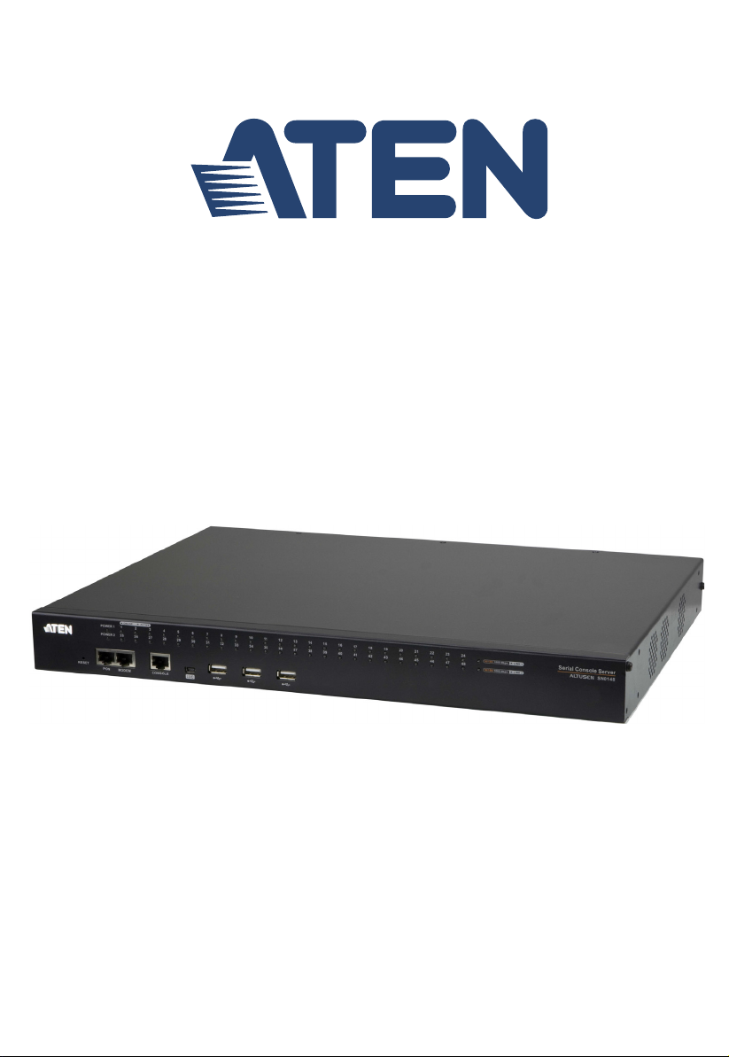
SN0108CO / SN0108COD Front View
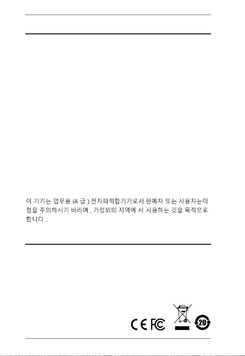
SN0116CO / SN0116COD Front View
Chapter 1. Introduction
No. Component Description
1 Power LEDs Lights when the unit is powered up and ready to operate.
2 Port LEDs The Port
Flashes Green: Active – data is being transmitted through
the port
3 LAN LEDs Primary and Secondary 10/100/1000 Mbps LAN LEDs.
RED: 10 Mbps
RED + GREEN (ORANGE): 100 Mbps
GREEN: 1000 Mbps
Flashes to indicate that the Serial Console Server is being
accessed over the LAN.
9
Page 24

Serial Console Server User Manual
No. Component Description
4 Reset Switch Note: This switch is recessed and must be pushed with a small
5 PON Port Reserved.
6 Modem Port For dial in connection should the unit be unavailable over the
7 Local Console
Port
8 Laptop USB
Console Port
9 USB Ports These three Type A female USB ports can be used to connect
object such as the end of a paper clip, or a ballpoint pen.
Pressing and releasing this switch when the unit is running
performs a system reset.
Pressing and holding this switch in for more than three
seconds when the unit is running resets its configuration to
the factory default settings.
Note: This does not clear User Account information.
See Clear Login Information, page 157, for
information on clearing user account information.
Pressing and holding this switch while powering on the
switch returns the unit to its factory default firmware level,
rather than the firmware version that the switch has been
upgraded to. This allows you to recover from a f ailed
firmware upgrade and gives you the opportunity to try
upgrading the firmware again.
Note: This operation should only be performed in the event
of a firmware upgrade failure that results in the device
becoming inoperable.
network. See Serial Console Server Installation, page 27, step
6 for installation details.
This RJ45 port allows for local administration and access
through a serial terminal connection to a computer. An SA0141
(DTE to DTE) adapter (included in the package) is required for
this connection.
This mini-USB port allows a PC or laptop to be connected for
local access and control. Connect to a PC or laptop to
automatically launch a terminal emulator to access the SN text
menu.
USB devices, such as USB storage devices (pen drive / hard
drive), USB hubs and USB SIM card Reader.
10
Page 25
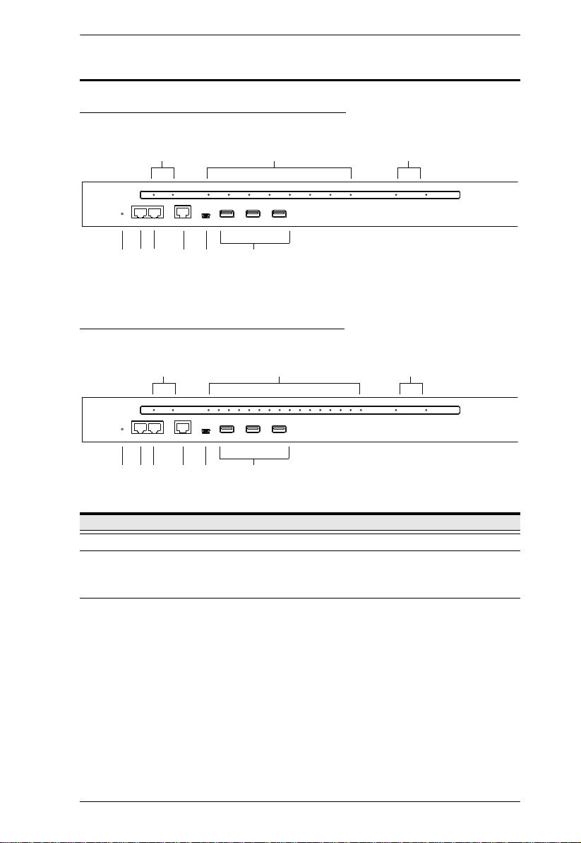
SN0132CO / SN0132COD Front View
Chapter 1. Introduction
1
56
4789
2
3
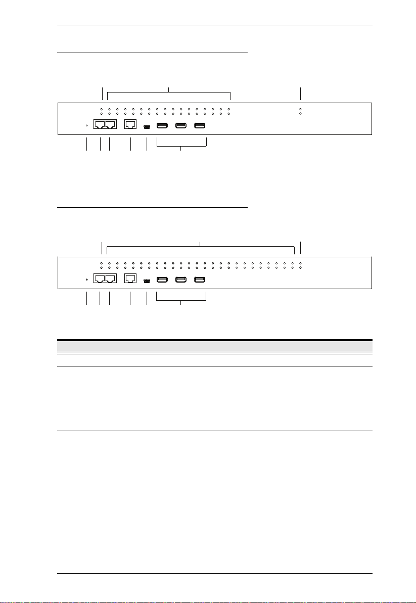
SN0148CO / SN0148COD Front View
1
56
4789
No. Component Description
1 Power LEDs Lights when the unit is powered up and ready to operate.
2 Port LEDs The Port LEDs provide status information about their
3 LAN LEDs Primary and Secondary 10/100/1000 Mbps LAN LEDs.
corresponding serial ports.
Lights Green: Online – the serial device attached to the port
is powered on and ready.
Flashes Green: Active – data is being transmitted through
the port
RED: 10 Mbps
RED + GREEN (ORANGE): 100 Mbps
GREEN: 1000 Mbps
Flashes to indicate that the Serial Console Server is being
accessed over the LAN.
2
3
11
Page 26

Serial Console Server User Manual
No. Component Description
4Reset SwitchNote: This switch is recessed and must be pushed with a small
5 PON Port Reserved.
6 Modem Port For dial in connection should the unit be unavailable over the
7 Local Console
Port
8 Laptop USB
Console Port
9 USB Ports These three Type A female USB ports can be used to connect
object such as the end of a paper clip, or a ballpoint pen.
Pressing and releasing this switch when the unit is running
performs a system reset.
Pressing and holding this switch in for more than three
seconds when the unit is running resets its configuration to
the factory default settings.
Note: This does not clear User Account information.
See Clear Login Information, page 157, for
information on clearing user account information.
Pressing and holding this switch while powering on the
switch returns the unit to its factory default firmware level,
rather than the firmware version that the switch has been
upgraded to. This allows you to recover from a failed
firmware upgrade and gives you the opportunity to try
upgrading the firmware again.
Note: This operation should only be performed in the event
of a firmware upgrade failure that results in the device
becoming inoperable.
network. See Serial Console Server Installation, page 27, step
6 for installation details.
This RJ45 port allows for local administration and access
through a serial terminal connection to a computer. An SA0141
(DTE to DTE) adapter (included in the package) is required for
this connection.
This mini-USB port allows a PC or laptop to be connected for
local access and control. Connect to a PC or laptop to
automatically launch a terminal emulator to access the SN text
menu.
USB devices, such as USB storage devices (pen drive / hard
drive), USB hubs and USB SIM card Reader.
12
Page 27
SN9108CO Front View
1 243
1 243
SN9116CO Front View
Chapter 1. Introduction
No. Component Description
1 Power LED Lights when the unit is powered up and ready to operate.
2 Port LEDs The Port LEDs provide status information about their
3 LAN LED Primary and Secondary 10/100/1000 Mbps LAN LEDs.
corresponding serial ports.
Lights Green: Online – the serial device attached to the port
is powered on and ready.
Flashes Green: Active – data is being transmitted through
the port
RED: 10 Mbps
RED + GREEN (ORANGE): 100 Mbps
GREEN: 1000 Mbps
Flashes to indicate that the Serial Console Server is being
accessed over the LAN.
13
Page 28

Serial Console Server User Manual
No. Component Description
4Reset SwitchNote: This switch is recessed and must be pushed with a small
object such as the end of a paper clip, or a ballpoint pen.
Pressing and releasing this switch when the unit is running
performs a system reset.
Pressing and holding this switch in for more than three
seconds when the unit is running resets its configuration to
the factory default settings.
Note: This does not clear User Account information.
See Clear Login Information, page 157, for
information on clearing user account information.
Pressing and holding this switch while powering on the
switch returns the unit to its factory default firmware level,
rather than the firmware version that the switch has been
upgraded to. This allows you to recover from a failed
firmware upgrade and gives you the opportunity to try
upgrading the firmware again.
Note: This operation should only be performed in the event
of a firmware upgrade failure that results in the device
becoming inoperable.
14
Page 29
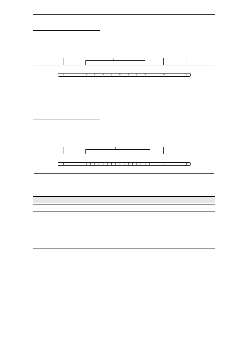
SN0108CO Rear View
Chapter 1. Introduction
1
2 3
4
SN0116CO Rear View
1
No. Component Description
1 Grounding
2 Power
3 LAN Ports The cables that connect the unit to the primary and the
4 Power Sockets The power cable(s) plugs in here.
5 Serial Ports The Cat 5e cables that connect to the serial devices or
2 3
4
Terminal
Switches
5
The grounding wire that is used to ground the unit attaches
here.
These standard rocker switches power the unit on and off.
backup network interfaces (10/100/1000 Mbps) plug in here.
RJ45-to-Serial adapters plug in here.
5
15
Page 30
Serial Console Server User Manual
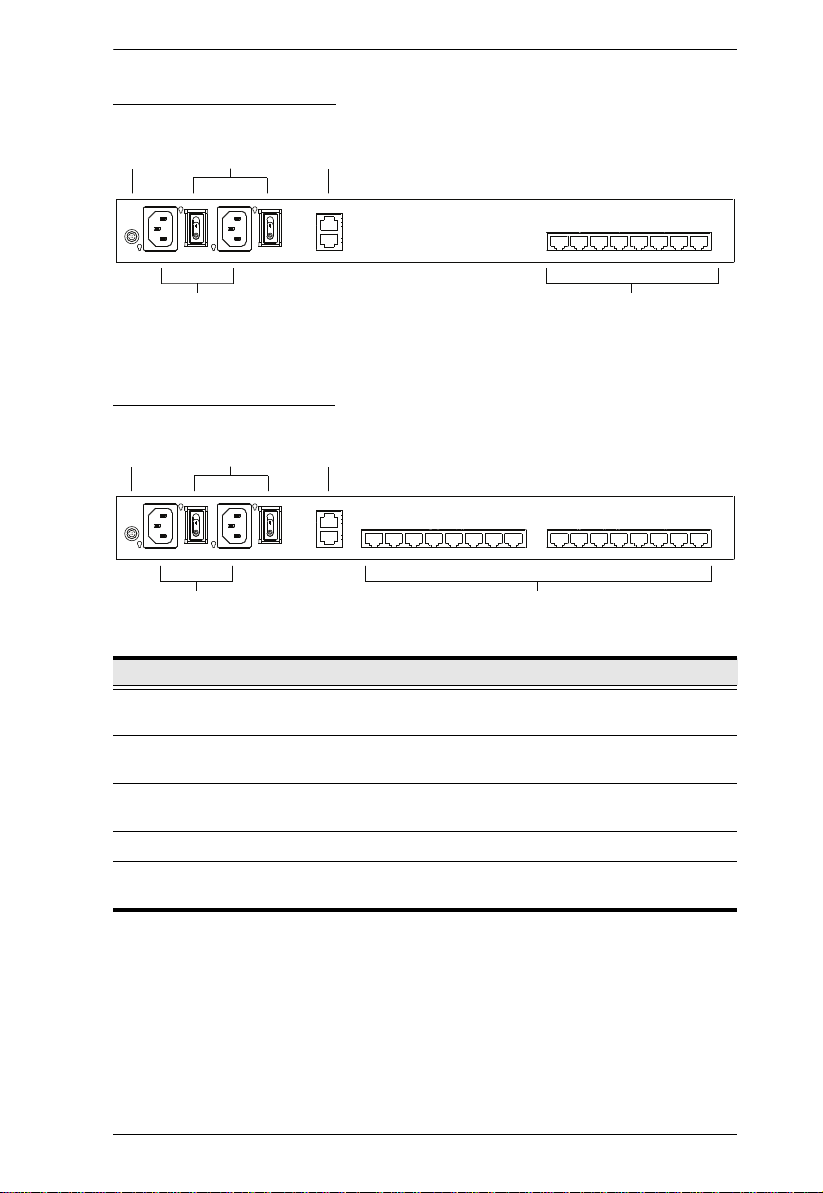
SN0108COD Rear View (DC Power)
12
4
5
3
SN0116COD Rear View (DC Power)
312
5
4
No. Component Description
1 Power
Switches
2 LAN Ports The cables that connect the unit to the primary and the
3 Serial Ports The Cat 5e cables that connect to the serial devices or
4 Grounding
Terminal
5 DC Terminal
Block
These standard rocker switches power the unit on and off.
backup network interfaces (10/100/1000 Mbps) plug in here.
RJ45-to-Serial adapters plug in here.
The grounding wire that is used to ground the unit attaches
here.
The electric leads from your power source connect to this
DC terminal block.
16
Page 31

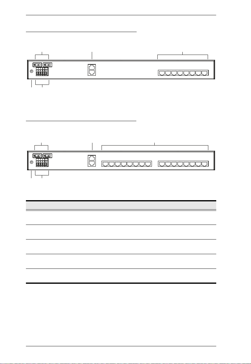
SN0132CO Rear View
Chapter 1. Introduction
142
3
5
SN0148CO Rear View
142
No. Component Description
1 Grounding
2 Power
3 LAN Ports The cables that connect the unit to the primary and the
4 Serial Ports The Cat 5e cables that connect to the serial devices or
5 Power Sockets The power cable(s) plugs in here.
5
3
Terminal
Switches
The grounding wire that is used to ground the unit attaches
here.
These standard rocker switches power the unit on and off.
backup network interfaces (10/100/1000 Mbps) plug in here.
RJ45-to-Serial adapters plug in here.
17
Page 32

Serial Console Server User Manual
4
3
12
5
312
4
5
SN0132COD Rear View (DC Power)
SN0148COD Rear View (DC Power)
No. Component Description
1 Power
These standard rocker switches power the unit on and off.
Switches
2 LAN Ports The cables that connect the unit to the primary and the
backup network interfaces (10/100/1000 Mbps) plug in here.
3 Serial Ports The Cat 5e cables that connect to the serial devices or
RJ45-to-Serial adapters plug in here.
4 Grounding
Terminal
5 DC Terminal
Block
The grounding wire that is used to ground the unit attaches
here.
The electric leads from your power source connect to this
DC terminal block.
18
Page 33

SN9108CO Rear View
152
3 4
152
3 4
SN9116CO Rear View
Chapter 1. Introduction
No. Component Description
1 Power Socket The power cable(s) plugs in here.
2 Power Switch This standard rocker switches power the unit on and off.
3 Grounding
Terminal
4 LAN Port The cable that connect the unit to the network interface (10/
5 Serial Ports The Cat 5e cables that connect to the serial devices or
The grounding wire that is used to ground the unit attaches
here.
100/1000 Mbps) plugs in here.
RJ45-to-Serial adapters plug in here.
19
Page 34

Serial Console Server User Manual
This Page Intentionally Left Blank
20
Page 35

Chapter 2
1. Important safety information regarding the placement of this
device is provided on page 139. Please review it before
proceeding.
2.
Make sure that the power to any device that you connect to the
installation has been turned off. You m
ust unplug the power cords
Hardware Setup
Before You Begin
Stacking and Rack Mounting
The Serial Console Server can be stacked on the desktop or rack mounted in a
variety of ways. The following sections take you through the procedures for
each method.
Stacking
The Serial Console Server can be placed on any appropriate level surface that
can safely support its weight plus the weight of its attached cables. To place the
device, or to stack units if you are daisy-chaining them, remove the backing
material from the bottom of the rubber feet that came with your package, and
stick them onto the device’s bottom panel at the corners, as shown in the
diagram, on the following page:
21
Page 36

Serial Console Server User Manual
Note: To ensure adequate ventilation, allow at least 5.1 cm on each side, and
12.7 cm behind the unit for power cord and cable clearance.
22
Page 37

Chapter 2. Hardware Setup
Phillips hex head
M3x8
Rack Mounting
The Serial Console Server can be mounted in a 19" (1U) rack. The mounting
brackets can screw into either the front or the back of the unit so that it can
attach to the front or the back of the rack.
Rack Mounting - Front
To mount the unit at the front of the rack, do the following:
1. Remove the two screws at the front of the unit.
2. Use the M3 x 8 Phillips head hex screws supplied with the rack mount kit
to screw the rack mounting brackets into the front of the unit.
23
Page 38

Serial Console Server User Manual
3. Position the device in the front of the rack and align the holes in the
mounting brackets with the holes in the rack.
4. Screw the mounting brackets to the rack.
Note: Cage nuts are provided for racks that are not pre-threaded.
24
Page 39

Chapter 2. Hardware Setup
Phillips hex head
M3x8
Rack Mounting - Rear
To mount the unit at the rear of the rack, do the following:
1. Remove the two screws at the rear of the unit.
2. Use the M3 x 8 Phillips head hex screws supplied with the rack mounting
kit to screw the rack mounting brackets into the rear of the unit.
3. Position the device in the rack and align the holes in the mounting brackets
with the holes in the rack.
25
Page 40

Serial Console Server User Manual
4. Screw the mounting brackets to the rear of the rack.
Note: Cage nuts are provided for racks that are not pre-threaded.
26
Page 41

Chapter 2. Hardware Setup
Serial Console Server Installation
SN0108CO / SN0116CO / SN0132CO / SN0148CO Installation
To set up your SN0108CO / SN0116CO / SN0132CO / SN0148CO
installation, refer to the Installation Diagram on page 29. The numbers in the
diagram correspond to the numbers of the instruction steps, below:
1. Use a grounding wire to ground the unit by connecting one end of the wire
to the Serial Console Server’s grounding terminal (located on the back
panel), and the other end of the wire to a suitable grounded object.
Note: Do not omit this step. Proper grounding helps to prevent damage to
the unit from surges or static electricity.
2. For each server or serial device with a DB-9 connector, connect a Cisco
Console Cable or a Cat 5e cable with RJ-45-to-DB-9(F) adapter between
its serial port and any available RJ-45 port on the Serial Console Server’s
rear panel.
Note: Refer to DB-9/DB-25 Interface on page 159 for pin assignments.
3. Connect a Cat 5e cable between a Cisco Network Switch (or any
compatible network switch) and any available RJ-45 port on the Serial
Console Server’s rear panel.
Note: For a compatible network switch, please make sure the RJ-45 port
pin definition of the target device matches the Serial Console Server.
4. Connect the Serial Console Server to the network by connecting both the
primary and backup LAN ports, located on the unit’s rear panel, to the
network with Cat 5e cables.
5. (Optional) If you choose to install a serial modem for OOB operation,
connect a Cisco Console Cable to a null modem adapter. Plug the DB-9
connector into the Modem and the RJ-45 connector into the Modem Port
on the Serial Console Server’s front panel.
6. (Optional) Connect a Cat 5e cable between an ATEN PDU and the PON
Port on the Serial Console Server’s front panel for power management.
7. (Optional) If you wish to use a console terminal connection, use a Cisco
Console Cable to connect between the Serial Console Server’s Local
27
Page 42

Serial Console Server User Manual
Console Port on the front panel and the DB-9 connector of a console
terminal (or a computer).
For the console terminal or computer without DB-9 connector, you can use
a Cat 5e cable with UC232B to connect between the Local Console Port
and the USB port of the console terminal (or the computer).
Note: The UC232B USB to RJ-45 (RS-232) Console Adapter is sold
separately. Contact you ATEN dealer for product information.
8. (Optional) If you are using a laptop USB console to control the Serial
Console Server locally, use the laptop USB console cable included in the
package to connect the laptop to the LUC port on the Serial Console
Server’s front panel.
9. (Optional) If you are using USB devices (such as USB storage devices)
with your Serial Console Server, connect them to these three Type A
female USB ports.
10. For AC models: Use the AC power cord provided with this package to
connect the SN0108CO/SN0116CO/SN0132CO/SN0148CO's Power
Socket to an AC power source. For DC models: Connect the DC power
source to the SN0108COD/SN0116COD/SN0132COD/SN0148COD's
DC terminal block.
11. Turn on the power switch.
28
Page 43

SN0108CO / SN0116CO / SN0132CO / SN0148CO Installation
7
8
9
56
4
10
11
2
3
1
Modem
ATEN PDU
Cat5
PC (COM)
Cisco Console Cable
USB LUC
Laptop
Cisco Console Cable
+ Null modem adapter
Cat5
PC (COM)
Cisco Console Cable
USB USB USB
SN0148CO (Front View)
SN0148CO (Rear View)
SELECT
PDU
CURRENT
OUTLET
CURRENTIPADDRESS
SENSOR1SENSOR
2
OUTLET STATUS
Network Switch
CISCO
Diagram
Chapter 2. Hardware Setup
Note: The example above shows a SN0148CO Serial Console Server. The
SN0108CO / SN0116CO / SN0132CO units have the same ports and switches
but with slightly different layouts.
See Components, page 9 for details.
29
Page 44

Serial Console Server User Manual
SN9108CO / SN9116CO Installation
To set up your SN9108CO / SN9116CO installation, refer to the Installation
Diagram on page 31. The numbers in the diagram correspond to the numbers
of the instruction steps, below:
1. Use a grounding wire to ground the unit by connecting one end of the wire
to the Serial Console Server’s grounding terminal (located on the back
panel), and the other end of the wire to a suitable grounded object.
Note: Do not omit this step. Proper grounding helps to prevent damage to
the unit from surges or static electricity.
2. For each server or serial device with a DB-9 connector, connect a Cisco
Console Cable or a Cat 5e cable with RJ-45-to-DB-9(F) adapter between
its serial port and any available RJ-45 port on the Serial Console Server’s
rear panel.
Note: Refer to DB-9/DB-25 Interface on page 159 for pin assignments.
3. Connect a Cat 5e cable between a Cisco Network Switch (or any
compatible network switch) and any available RJ-45 port on the Serial
Console Server’s rear panel.
Note: For a compatible network switch, please make sure the RJ-45 port
pin definition of the target device matches the Serial Console Server.
4. Connect the Serial Console Server to the network by connecting the LAN
port to the network with Cat 5e cables.
5. (Optional) If you choose to install a serial modem for OOB operation,
connect a Cisco Console Cable to a null modem adapter. Plug the DB-9
connector into the Modem and the RJ-45 connector into any available RJ45 port on the Serial Console Server’s front panel.
6. For AC models: Use the AC power cord provided with this package to
connect the SN9108CO/SN9116CO's Power Socket to an AC power
source.
7. Turn on the power switch.
30
Page 45

SN9108CO / SN9116CO Installation Diagram
Chapter 2. Hardware Setup
31
Page 46

Serial Console Server User Manual
This Page Intentionally Left Blank
32
Page 47

Chapter 3
Super Administrator Setup
Overview
This chapter discusses the administrative procedures that the Super
Administrator performs to get the Serial Console Server set up for the first
time.
First Time Setup
Once the Serial Console Server has been cabled up, the Super Administrator
needs to set up the unit for operation. This involves setting the network
parameters, and changing the default Super Administrator login. The most
convenient way to do this for the first time is from a local console (local VT
console or a local computer running terminal application software, such as
Microsoft HyperTerminal), or a Laptop USB Console (LUC) running the
SNViewerUSB application (SN0108CO / SN0116CO / SN0132CO /
SN0148CO only). Setup can also be done remotely over the Web via the GUI
using the unit’s IP address.
Note: For remote methods of setting up the network, see IP Address
Determination, page 150.
Local Login
You can log in locally from a computer or laptop (SN0108CO / SN0116CO /
SN0132CO / SN0148CO only) connected directly to the Serial Console Server
(see Serial Console Server Installation, page 27). There are two methods for
logging in locally SNViewerUSB and HyperTerminal.
The local login Main Menu is the text based equivalent of the browser based
configuration and control functions described throughout this manual. You can
reference the detailed information provided for the web browser version
(Browser Login, page 37) as you work your way through the sub-menus to
configure the settings discussed in this chapter.
33
Page 48

Serial Console Server User Manual
Laptop USB Console (LUC) Login - SNViewerUSB
The SNViewerUSB application appears automatically when a Laptop USB
Console (LUC) connection (SN0108CO / SN0116CO / SN0132CO /
SN0148CO only) has been established, and you will be prompted to log in, as
shown here:
Since this is the first time you are logging in, use the default Username:
administrator; and the default Password: password.
Console Login - HyperTerminal
Once a physical connection from a computer to the Serial Console Server has
been made you can establish a HyperTerminal session using the instructions
below.
1. Open HyperTerminal, and configure the port settings for the COM1 port:
34
Page 49

Chapter 3. Super Administrator Setup
Bits per Second: 9600, Data Bits: 8, Parity: None, Stop bits: 1, Flow Control:
None.
2. When configured correctly the login prompt appears, as shown here:
Since this is the first time you are logging in, use the default Username:
administrator; and the default Password: password.
Local Console Main Menu
After you log in via HyperTerminal or SNViewerUSB the text based menu
appears:
The Main Menu is the text based equivalent of the browser based configuration
and control functions described throughout this manual. You can reference the
information provided for the browser version as you work your way through
the sub-menus.
35
Page 50

Serial Console Server User Manual
Remote Login
You can log in remotely from a computer running Telnet, PuTTY, or via Web
Browser.
The remote login Main Menu for Telnet and PuTTY are a text bas ed equivalent
of the browser based GUI and control functions as described throughout this
manual. You can reference the detailed information provided for the web
browser version (Browser Login, page 37) as you work your way through the
text sub-menus and configure the settings discussed in this chapter.
Telnet Login
Start Telnet, type “open 192.168.0.60”, press Enter, and a login prompt will
appear, as show here:
Since this is the first time you are logging in, use the default Username:
administrator; and the default Password: password.
PuTTY Login
Start PuTTY, enter the Serial Console Server’s default IP address
(192.168.0.60), click Open, and a login prompt will appear, as shown here:
Since this is the first time you are logging in, use the default Username:
administrator; and the default Password: password.
36
Page 51

Chapter 3. Super Administrator Setup
Browser Login
Once the Serial Console Server has been connected to the LAN, it can be
accessed via an Internet browser running on any platform. To access the Serial
Console Server, do the following:
1. Open the web browser and specify the default IP address (192.168.0.60) of
the Serial Console Server in the browser's location bar, and press Enter.
2. When a Security Alert dialog box appears, accept the certificate, it can be
trusted.
Once you accept the certificate(s), the login page appears:
3. Since this is the first time you are logging in, use the default Username:
administrator; and the default Password: password.
Note: For security purposes, you should change these to a unique Username
and Password. (See Changing the Super Administrator Login, page 39
for details.)
After you successfully log in, the Main Page appears:
37
Page 52

Serial Console Server User Manual
Setup
Network Setup
To set up the network, do the following:
1. Click the Device Management tab.
2. Select the Network tab.
3. Fill in the fields according to the information provided under Network,
page 100.
38
Page 53

Chapter 3. Super Administrator Setup
Changing the Super Administrator Login
To change the default Super Administrator Username and Password, do the
following:
1. At the top of the screen, click the User Management tab.
The User Management page has a list of Users and Groups in the Sidebar
at the left, and a more detailed list of users – with more information about
them – in the large central panel. Since this is the first time the page is
being accessed, only the Super Administrator appears:
2. Click on the account in the left panel or select it in the central panel, then
click Modify (at the bottom of the page.)
The User Information page appears:
3. Change the Username and Password to something unique.
39
Page 54

Serial Console Server User Manual
4. Enter the password again in the Confirm Password field to confirm it is
correct.
5. Click Save (located at the bottom of the page).
6. When the dialog box informing you that the change completed
successfully appears, Click OK.
40
Page 55

Chapter 4
The User Interface
Overview
Once you have successfully logged in, the Serial Console Server’s Main Page
appears. The look of the page varies slightly, depending on which method you
used to log in. Each of the interfaces is described in the sections that follow.
Access
The Serial Console Server can be accessed from a local console (locally
connected computer or laptop) running terminal application software (such as
Microsoft HyperTerminal) or the SNViewerUSB application; or from a remote
computer using Telnet (SSH), PuTTY, or web-based browser (see First Time
Setup, page 33 for details).
No matter which access method you choose, the Serial Console Server’s
authentication procedure requires you to submit a valid username and
password. If you supply invalid login information, the authentication routine
will return an Invalid Username or Password, or Login Failed message. If you
see this type of message, log in again with a correct username and password.
Note: If the number of invalid login attempts exceeds a specified amount, a
timeout period is invoked. You must wait until the timeout period
expires before you can attempt to log in again. See Login Failures,
page 119 for further details.
41
Page 56

Serial Console Server User Manual
Local Console Operation
When a local console is attached (SN0108CO / SN0116CO / SN0132CO /
SN0148CO only, see page 27), you can use the HyperTerminal or
SNViewerUSB application to log in (See Local Login, page 33 for details).
Simply key in your valid Username and Password, then hit [Enter] to b ring up
the Local Console Main Page.
The Main Menu is the text based equivalent of the browser based configuration
and control functions described throughout this manual. You can reference the
information provided for the browser version as you work your way through
the sub-menus.
Note: 1. As with the browser version, access to many of these sub-menus are
restricted by the user’s permissions. If you select a submenu that you
are not authorized for, nothing happens.
2. Some of the sub-menus do not have an Exit choice. In these cases, you
can return to the previous menu without making changes by pressing
Enter twice.
3. You can bring up the Main Menu at any time during your session.
4. This menu can also be accessed from remote terminal sessions, such
as Windows Telnet Client, and PuTTY.
When you have finished with your session, bring up the Main Menu and press
Q to log out. After you are offline, you can simply close the window.
42
Page 57

Chapter 4. The User Interface
Remote Operation
You can access the Serial Console Server remotely using a web browser, or text
based terminal application such as Telnet or PuTTY, as described below.
Web Browser Login
Serial Console Server units can be accessed via an Internet browser running on
any platform. To access the Serial Console Server, do the following:
1. Open the browser and specify the IP address (See Browser Login, page 37
for details) of the Serial Console Server you want to access in the
browser's location bar.
2. When a Security Alert dialog box appears, accept the certificate – it can be
trusted. If a second certificate appears, accept it as well.
Once you accept the certificate(s), the login page appears:
3. Provide your username and password (see Browser Login, page 37), then
click Login to bring up the Web Browser Main Page, described on the
next page.
43
Page 58

Serial Console Server User Manual
The Web Browser Main Page
To ensure multi-platform operability, access to the Serial Console Server can
be accomplished with most standard web browsers. The chapters following this
one give detailed information about each section of the web browser. Once
users log in and are authenticated (see page 43), the Web Browser Main Page
comes up, with the Port Access page displayed:
Note: The screen depicts a Super Administrator’s page. Depending on a user’s
type and permissions, not all of these elements appear.
Page Components
The web page screen components are described in the table, below:
No. Item Description
1 Tab Bar The tab bar contains the Serial Console Server main
2 Menu Bar The menu bar contains operational sub-categories
3 Sidebar The Sidebar provides a tree view listing of ports that
44
operation categories. The items that appear in the
tab bar are determined by the user’s type, and the
authorization options that were selected when the
user’s account was created.
that pertain to the item selected in the tab bar. The
items that appear in the menu bar are determined by
the user’s type, and the authorization options that
were selected when the user’s account was created.
relate to the various tab bar and menu bar selections.
Clicking a node in the Sidebar brings up a page with
the details that are relevant to it.
There is a Filter button at the bottom of the Sidebar
that lets you expand or narrow the scope of the ports
that appear in the tree.
Page 59

Chapter 4. The User Interface
No. Item Description
4 About About provides information regarding the Serial
Console Server’s current firmware version.
5 Logout Click this button to log out of your Serial Console
Server session.
6 Welcome Message If this function is enabled (see Welcome Message,
page 67), a welcome message displays here.
7 Interactive Display Panel This is your main work area. The screens that appear
here reflect your menu choices and Sidebar node
selection.
45
Page 60

Serial Console Server User Manual
The Tab Bar
The number and type of icons that appear on the Tab Bar at the top of the page
are determined by the user’s type (Super Administrator, Administrator, User)
and the permissions assigned when the user’s account was created. The
chapters following this one give detailed information about each section of the
web browser. The functions associated with each of the icons are explained in
the table below:
Icon Function
Port Access: The Port Access page is used to access and control the
devices on the Serial Console Server installation. This page is
available to all users. Port Access is discussed on page 59.
User Management: The User Management page is used to create
and manage Users and Groups. It can also be used to assign devices
to them. This tab is available to the Super Administrator, as well as
administrators and users who have been given User Management
permission. The tab doesn’t appear for other administrators and users.
User Management is discussed on page 81.
Device Management: The Device Management page is used to
configure and control the overall operation of the Serial Console
Server. This page is available to the Super Administrator, as well as
administrators and users who have been given Device Management
permission. The tab doesn’t appear for other administrators and users.
Device Management is discussed on page 97.
Log: The Log page displays the contents of the log file. The Log page
is discussed on page 127.
Maintenance: The Maintenance page is used to install new firmware;
backup and restore configuration and account information; restore
default values; and import Certificates. This page is available to the
Super Administrator (and Administrators and Users with Maintenance
permission). The icon doesn’t display on the page of ordinary
administrators and users. The Maintenance page is discussed on
page 131.
There are two small icons at the extreme right of the page. Their functions are
described in the table, below:
Icon Function
Click this icon to bring up a panel with information about the Serial
Console Server’s firmware version.
Click this icon to log out and end your Serial Console Server session.
46
Page 61

Chapter 4. The User Interface
SNViewer
The SNViewer is the main application used to access serial devices via web
browser. The SNViewer opens from the Port Access - Connections page, when
you click the Telnet or SSH button for a serial device (see Telnet/SSH, page 63
for details). When the SNViewer opens there is a Control Panel toolbar that
appears when your mouse moves over it, which allows you to configure your
session, as shown here:
SNViewer Control Panel
The SNViewer provides a Control Panel that is hidden at the upper center of
the screen, and becomes visible when your mouse moves over it. The panel
consists of three rows: an icon row at the top, and two text rows below it:
By default, the upper text row shows the width and height of the window
size. As the mouse pointer moves over the icons in the icon bar, however,
the information in the upper text row changes to describe the icon's
function. In addition, if a message from another user is entered in the
message board, and you have not opened the message board in your
session, the message board window will pop open automatically.
The lower row shows the IP address and port of the device you are
accessing on the left side, and the connection status on the right.
47
Page 62

Serial Console Server User Manual
Control Panel Functions
The Control Panel functions are described below and in the following sections:
Icon Function
This is a toggle. Click to make the Control Panel appear Always On
–
i.e., always displays on top of the SNViewer screen. Click
To p
–
again to have it display in Auto Hide mode
appear when the mouse is moved over it.
Use this to copy the selected text on the screen.
Use this to copy all text that is displayed on the screen.
Use this to paste the copied text.
Use this icon to toggle Logging on / Logging off. This starts a log file
of characters sent from the serial device to the SNViewer. You must
first create and import a text based log file (See Terminal Settings,
Others - Log File, page 53).
allowing it to only
48
Use this to browse for data files to import (see Data Import,
page 49).
Use this to change the page encoding (see Encode, page 50).
Use this icon to enable broadcasting. Broadcasting allows you to
access and make changes on a single port and the same changes
will be made across all Broadcast Ports. Before using the
broadcast function, set the Broadcast Timeout and Broadcast Ports
(see Preferences, page 66 for details).
For broadcasting to work, you must first access a port set as a
Broadcast Port and then click the Broadcast icon on the control
panel.
Click to send a Break command.
Page 63

Icon Function
Use this to reset the terminal to its default settings.
Click to bring up the Message Board (see The Message Board,
page 50).
Click to open a window and create a list of custom text macros (see
Macros, page 51).
Use this to change the font, color and other SNViewer settings (see
Terminal Settings, page 52).
Use this button to adjust the width of the SNViewer window.
Click to exit the viewer.
Chapter 4. The User Interface
Data Import
The Data Import page opens a standard browse menu to import data
files, as shown below:
49
Page 64

Serial Console Server User Manual
Encode
Encoding allows you select which type of encoding you want to use.
Make your selection from the drop down menu and click OK, as
shown below:
The Message Board
The Serial Console Server supports multiple user logins, which may
cause access conflicts. To alleviate the problem, a message board has
been provided, which allows users to communicate with each other:
Message Display Panel
Messages that users post to the board are display in this panel.
Compose Panel
Key in the messages that you want to post to the board in this panel. Click Send
to post the message to the board.
User List Panel
The username and IP address of all the logged in users are listed in this panel.
50
Page 65

Chapter 4. The User Interface
If you check All Users, messages are posted to all users. To post a
message to one individual user, select the user's name before sending your
message.
If a user's name is selected, and you want to post a message to all users,
select All Users before sending your message.
Macros
Macros allow you to create custom text macros to use within the
SNViewer application. When you click the Macros icon the following
screen appears:
Simply check a box, type in the text macro and click Save. Use the associated
function key (F1-F12) to run the custom text macro(s) you created.Terminal
Application
You can log in remotely using a text based terminal application such as Telnet,
or PuTTY. For information on how to connect and login, see Remote Login,
page 36 for details.
The Telnet and PuTTY Main Menus are the text based equivalent of the
browser based configuration and control functions described throughout this
manual. You can reference the information provided for the browser version as
you work your way through the sub-menus. Once you login, the following text
based menu’s appear:
51
Page 66

Serial Console Server User Manual
Terminal Settings
The Terminal Settings page allows you make changes to the
appearance of the terminal window, as described below:
Category Description
Font Click Change to configure the SNViewer’s Font settings. You can
Color Select an Option: Foreground color, Background Color, Cursor Text
change the Font type, Size, and Style. On the right side of the
window you can view an example of the font you have set.
color, or Cursor Color, and Click Change to adjust the color settings.
Use the HSL, Swatches, and HSV tabs to make detailed adjustments
and select the colors.
Below the tab is a Preview section you can use to see how the color
change will look.
Click OK to save the changes; Cancel to remove the changes and
exit; or Reset to revert to the default color settings.
52
Page 67

Category Description
Others Use this section to set:
Implicit CR in every LF: Checking this box adds an extra Carriage
Return when the [Enter] key is used, so the cursor returns flush on
the left margin. Use this function if the text is not lining up on the
left margin after you hit [Enter].
Backspace is Delete Key
Local echo: An echo is a response from the serial device of
character(s) that have been input.
Auto: Characters that are typed in are echoed but not
displayed on the screen.
Force On: Characters that are typed in are echoed and
displayed on the screen as they are entered. Passwords are
displayed on the screen if this mode is used.
Force Off: Characters are not echoed from the serial device.
Buffer Size: This is the maximum size of the Log file.
Log File: The log file generates a log of characters sent from the
connected serial device to the SNViewer. The log must first be
created as a text file using an external editor such as Note or
Microsoft Word, then opened here. Next you must turn Logging on
from the SNViewer Control Panel (see Control Panel Functions,
page 48).
Chapter 4. The User Interface
53
Page 68

Serial Console Server User Manual
Terminal Application
You can log in remotely using a text based terminal application such as Teln et,
or PuTTY. For information on how to connect and login,see Remote Login,
page 36 for details.
The Telnet and PuTTY Main Menus are the text based equivalent of the
browser based configuration and control functions described throughout this
manual. You can reference the information provided for the browser version as
you work your way through the sub-menus. Once you login, the following text
based menu’s appear:
Telnet Menu-Driven Text UI
PuTTY Menu-Driven Text UI
54
Page 69

Chapter 5
Port Operating Modes
Overview
To cover a broad range of serial applications, the Serial Console Server’s COM
ports support several port operating modes. These include Console
Management and Console Management Direct modes for device control; and
Real COM Port, Virtual Modem, TCP Server, TCP Client, and UDP Mode for
Serial-to-Ethernet connectivity and applications that require COM ports, serial
tunneling, or where TCP/UDP Socket functionality is needed. An explanation
of the functions performed by the various operating modes is provided in the
sections that follow.
The Operating Mode is selectable from the Port Access - Properties page,
under the Operation Mode tab, as shown above. From this page you can set the
Port Operating Modes that are discussed in this chapter. See Operating Mode,
page 73, for further details on configuring all the settings.
55
Page 70

Serial Console Server User Manual
Operating Mode
For detailed information about the settings in each of the Operating Modes, see
Operating Mode, page 73.
Console Management
Console Management mode is the most common Operating Mode used,
allowing users to establish Telnet or SSH sessions to the Serial Console Server
to manage the serial devices. In this mode users can log in using the web
browser’s built in SNViewer application via Telnet or SSH; remotely via Telnet
or PuTTY; or directly using the HyperTerminal or SNViewerUSB
applications.
For information about configuring Console Management settings, see page 73.
Note: Be sure that the Socket entry specified on the Network page corresponds
to the port that the device listens on. 5001 is the Serial Console Server’s
default setting (see Network, page 100, and Base Socket, page 101).
Real COM Port
This mode is used in conjunction with a virtual COM port driver installed on
the remote user’s local computer. When the Serial Console Server’s COM port
is set to this mode, the device connected to the port appears as if it were a
device directly connected to a COM port on the remote user’s local computer.
This m ode is use ful with de vices such PO S terminals, Bar Code Readers, Serial
printers, etc. since it allows you to use software that was written for pure serial
communication applications.
The Serial Console Server comes with Real COM drivers for Windows
systems and TTY drivers for Linux systems.
For information about configuring Real COM Port settings, see page 73.
TCP Server / TCP Client (Serial Tunnel)
TCP (Transmission Control Protocol) provides a reliable transport layer for
transmitting serial data over the TCP protocol via socket programming.
TCP Server (RAW TCP)
In TCP Server (RAW TCP) mode, data transmission is bidirectional. In this
mode, the host computer initiates contact with the Serial Console Server and
requests a connection to its serial port.
56
Page 71

Chapter 5. Port Operating Modes
Once the connection is established, the host receives data from the serial
device. From this point on, data can be transmitted between the host and the
device in both directions.128-bit/256-bit SSL (TLS v1.0 / TLS v1.1 / TLS v1.2)
data encryption is supported in this operating mode.
The Serial Console Server supports simultaneous connections from up to 16
host computers in this mode, allowing multiple computers to communicate
with the serial device at the same time.
For information about configuring TCP Server settings, see page 76.
Note: Be sure that the Socket entry specified on the Network page corresponds
to the port that the device listens on. 5301 is the Serial Console Server’s
default setting. (see Network, page 100, and Base Socket, page 101).
TCP Client
In TCP Client mode, when serial data comes into the Serial Console Server’s
serial port, the Serial Console Server initiates contact with the host computer
and begins sending serial data to the to the host. The Serial Console Server can
send data to up to 16 host computers simultaneously, and supports 128-bit/256bit SSL (TLS v1.0 / TLS v1.1 / TLS v1.2) data encryption in this operating
mode.
For information about configuring TCP Client settings, see page 76.
UDP Mode
UDP (User Datagram Protocol) Mode is faster and more efficient at
communications than TCP. In UDP mode, communications are bilateral. A
serial device can send data to, and receive data from, up to 16 host computers
via the Serial Console Server’s COM port.
Because it doesn’t perform error checking in the thorough way that TCP does,
UDP is more suitable for real time applications (such as message display) than
the slower TCP which is optimized for data accuracy.
For information about configuring UDP Mode settings, see page 78.
Virtual Modem
In Virtual Modem mode, the Serial Console Server’s COM port emulates a
modem. The port acts as if it were a real modem for communication with a
remote server. This allows software designed to transmit data over a serial
modem-to-modem link, to perform serial operations over a TCP/IP Ethernet
connection. In this mode, the Serial Console Server “dials into” the remote
57
Page 72

Serial Console Server User Manual
server’s IP specifying the appropriate port address for the transmission. For
example:
atd 10.0.100.101:5000
A detailed description of the data structures and related functions of the Serial
Console Server’s virtual modem function is provided on page 154.
For information about configuring Virtual Modem settings, see page 78.
Note: 128-bit/256-bit SSL (TLS v1.0 / TLS v1.1 / TLS v1.2) data encryption
is supported in this operating mode.
Console Management Direct
In this mode, users establish a Telnet or SSH session directly from a PC to a
server or serial device connected to a port. There is no need to log in to the
Serial Console Server via web browser to establish the connection. Users can
log in to a serial device using Telnet, SSH or PuTTY directly from a PC.
For information about configuring Console Management Direct settings, see
page 78.
Disabled
In this mode, the serial port on the Serial Console Server is disabled.
58
Page 73

Chapter 6
Port Access
Overview
Once you have logged in from a web browser, the Main Screen appears with
the Port Access - Connections page displayed:
The Connections page is organized into several main areas. All the devices,
ports, and outlets that a user is permitted to access are listed in the Sidebar at
the left of the page.
After selecting a port in the Sidebar, clicking entries on the menu bar opens
information and configuration pages related to the item selected in the Sidebar.
59
Page 74

Serial Console Server User Manual
The Sidebar
All connected Serial Console Servers, port devices and PDU devices –
including their ports and outlets – are listed in a tree structure in the Sidebar at
the left of the screen:
The Sidebar Tree Structure
The characteristics of the Sidebar tree structure are:
Users are only allowed to see the devices and ports that they have access
permission for.
Ports become green to show that the serial device is online.
Ports become green and a green tick is shown when they are accessed by a
user.
Ports and child devices can be nested under their parent devices. Click the
+ in front of a device to expand the tree and see the ports nested
underneath it. Click the - to collapse the tree and hide the nested ports.
60
Page 75

Chapter 6. Port Access
Filter
A “Show” is displayed on the bottom-left hand corner of the page. It is a filter
function that allows you to control the number and type of ports that display in
the Sidebar. When you click “Show”, the bottom of the panel changes to look
similar to the image below:
The meanings of the choices are explained in the following table:
Choices Explanation
Search If you key in a search string and click Search, only port names
that match the search string display in the tree. Wildcards (?
for single characters; * for multiple characters) and the
keyword or are supported, so that more than one port can
show up in the list.
For example:
1. If you key in Web*, both Web Server 1 and Web Server 2
show up in the list.
2. If you key in W*1 or M*2, both Web Server 1 and Mail
Server 2 show up in the list.
61
Page 76

Serial Console Server User Manual
Connections
The main panel on the Connections page displays the Port List. From here you
can select and connect to the serial devices via the port they are connected to.
Heading Description
Port Number This column represents the physical port that the device is
Port Name This column shows the port name which can be changed from
Status This column shows the On or Off status of a device connected to
Busy This column will show Busy when the port is being accessed by
Operation Mode This column lists the Work Mode that the port is set to for
Operation Lists Console Management access methods: Teln et and SSH for
Port Shows the respective Telnet and SSH Port number configured for
connected to on the rear of the Serial Console Server.
the Port Access - Properties page (See page 70 for details).
the port. If no device is connected to the port a “-” will appear.
a user through the Serial Console Server.
access. The most common setting is Console Management,
which is set on the Port Access - Properties page, under the
Operation Mode tab (See Operating Mode, page 73 for details).
Note: Console Management is the means of accessing a serial
device for operations on it.
managing a port device. Clicking either one opens the SNViewer
application to manage that serial device (See Telnet/SSH,
page 63, below). Dump Buffer: This button allows you to dump
and view the buffer log of activity conducted on the device. Click
to save the log. (See Save & Copy, page 71 for details).
access to the serial device (See Service Ports, page 101 for
details).
62
Page 77

Chapter 6. Port Access
Telnet/SSH
To access a serial device connected to the Serial Console Server, click the
port’s Telnet or SSH button from the Port Access - Connections page:
The Serial Console Server opens SNViewer to start your session with the serial
device, and a screen similar to the one below appears:
From the SNViewer can you login and perform management activities on the
serial device. For more information on using the SNViewer, see SNViewer,
page 47 for details.
Port Attributes
Clicking a device on the sidebar from the Port Access - Connections page
brings up the Port Attributes page with detailed information about the device
and Power Over the Net™ reboot options, as shown here:
63
Page 78

Serial Console Server User Manual
From here you can use the Telnet, SSH, and Dump Buffer buttons at the
bottom of the page.
64
Page 79

Chapter 6. Port Access
Favorites
The Favorites tab allows you to keep all the connections that you access most
frequently in one convenient place. To add a port to Favorites, right-click on it
from the sidebar and select Add to Favorites, or select a port and click Add.
The layout and functions available on the Favorites tab are exactly the same as
those found on the Port List tab (See Connections, page 62 for details).
History
The History page provides a record of each time that a port was accessed. It
provides quick access to the most recently used ports. You can access a port
shown in the main panel by clicking it’s Telnet or SSH button.
If there are more entries than there is room on the screen, a scroll bar
appears to let you scroll up and down to see the entire record.
To clear the record, click the Delete button at the bottom right of the page.
You can change the sort order by clicking the column headings.
65
Page 80

Serial Console Server User Manual
Preferences
The Preferences page allows users to set up their own, individual, working
environments. The Serial Console Server stores a separate configuration record
for each user profile, and sets up the working configuration according to the
Username that was keyed into the Login dialog box:
The page settings are explained in the following table:
Setting Function
Language Select the language that the web GUI uses.
Logout Timeout If there is no user input for the amount of time set with this
Broadcast Timeout If there is no user input for the amount of time set here, the
Viewer You can choose which viewer is used when accessing a serial
66
function, the user is automatically logged out. Once logged out, a
login is necessary before the Serial Console Server can be
accessed again.
Broadcast function is automatically ended. Key in a value from
0
–
240 seconds. A setting of 0 (zero) has the same effect as
disabling the function.
For more information on the Broadcast function, see Broadcast
Ports within this table.
device:
Auto Detect will select the appropriate viewer based on the
web browser used; WinClient for Windows Internet Explorer,
Java Client for other web browsers (ex. Firefox).
Java Client will open the Java based viewer regardless of the
web browser being used.
Page 81

Chapter 6. Port Access
Setting Function
Welcome Message You can choose to hide or show the Welcome Message and/or
Broadcast Ports Select the ports to receive broadcast commands by selecting the
Save Click Save to save any changes made to the Preferences
Changing a
Password
User Name displayed in the submenu bar. The default is
disabled.
boxes. Selecting Broadcast Ports allows you to access and make
changes on a single port and the same change will be made
across all Broadcast Ports.
Note: For broadcasting to work, you must access a Broadcast
Port using the SNViewer and turn Broadcast on from the Control
Panel (See Control Panel Functions, page 48).
settings.
In the Browser GUI, to change a user’s password, key in the
old password and new password into their input boxes; key the
new password into the Confirm input box, then click Change
Password to apply the change.
Sessions
The Session page lets the administrator and users with User Management
permissions see at a glance which users are currently logged into the Serial
Console Server, and provides information about each of their sessions.
Note: 1. The Session page is not available for ordinary users.
2. Users with User Management permissions can only see the sessions
of ordinary users.
67
Page 82

Serial Console Server User Manual
3. The sort order of the information displayed can be changed by
clicking the column headings.
The meanings of the headings at the top of the page are fairly straightforward.
Heading Description
Username Refers to the user that logged in.
Service Displays the type of session (HTTP, HTTPS) established to log in.
IP Refers to the IP address that the user has logged in from.
Login Time Indicates the date and time the user logged in.
Last Access Indicates when the user last accessed the system for use.
User Type Lists the type of user who has logged in: SA (Super Administrator),
Administrator (Administrator), or Normal user (User).
This page also gives the administrator the option of forcing a user logout by
checking the Select box for the user and clicking Kill Session at the bottom of
the main panel.
Access
Administrators use the Access page to set user and group access and
configuration rights for Serial Console Server ports and PDU devices. The
Access page only appears for those users with User Management permissions
and is not available for other users. Access rights can be set on a user-by-user
or a group-by-group basis. See User Management, page 81, to setup groups
and users.
68
Page 83

Chapter 6. Port Access
Use the radio buttons to configure access rights on the User Access and Group
Access page. The meaning of the columns are given in the table, below:
User Access Each User created on the Serial Console Server (excluding Super
Group Access Each Group created on the Serial Console Server is listed to set
Access Rights The Access columns are where access rights are set. The
Config Sets or denies permission for the user to make changes to a
Power Supply This column permits/restricts the configuration and power
Administrator accounts) is listed to set access and configuration
rights for each device listed on the sidebar. Select a device from
the Sidebar to set the access and configuration rights of each
User.
access and configuration rights for each device listed on the
sidebar. Select a device from the Sidebar to set the access and
configuration rights of each Group.
meaning of each is explained below.
Full Access The user can view the device and can
perform operations on the device.
View Only The user can only view the device; he
No Access The device will not show up on the
port’s configuration settings. A check mark
user has permission; an empty box means that the user does not
have permission.
operation of ports that have Power Over the Net™ devices
connected to them. A check mark
permission; an empty box means that the user does not have
permission.
cannot perform any operations on it.
User's list on the Main Screen.
( √ )
indicates that the
( √ )
indicates that the user has
69
Page 84

Serial Console Server User Manual
Properties
When you click the Properties tab, the Port Settings List page appears:
When a port is double clicked from the Port Settings List or from the Sidebar,
the Properties page appears and looks similar to the one below:
This panel allow s you to make configuration settings for the selected port, as
explained in the table below:
Setting Meaning
Port ID Each port on the Serial Console Server has a port ID number. The
70
value in this field indicates the port that is being configured.
Page 85

Chapter 6. Port Access
Setting Meaning
Port Name You can give a port an appropriate name by editing the Port Name
Interface Choose between Auto (default), DTE or DCE.
Baud Rate
Data Bits This sets the number of bits used to transmit one character of data.
Parity This bit checks the integrity of the transmitted data. Choices are:
Stop Bits This indicates that a character has been transmitted. Set this to match
Flow Control This allows you to choose how the data flow will be controlled.
Toggle DTR Enabling this parameter allows the DTR signal to toggle between
field.
This sets the port’s data transfer speed. Choices are from 300
230400 (drop down the list to see all options). Set this to match the
baud rate setting of the connected device. Default is 9600 (which is a
default setting for many serial devices).
Choices are: 5, 6, 7 and 8. Set this to match the data bit setting of the
connected device. Default is 8 (which is a default setting for many
serial devices).
None; Odd; Even. Set this to match the parity setting of the connected
device. Default is None (which is a default setting for many serial
devices).
the stop bit setting of the connected device. Choices are: 1, 1.5, and
2. Default is 1 (which is a default setting for many serial devices).
Choices are: None, Hardware (RTS/CTS), and XON/XOFF. Set this to
match the flow control setting of the connected device. Default is
None.
enabled and disabled. A check mark
( √ )
enables Toggle DTR.
–
Save & Copy
At the bottom right side of each Properties page you can click Save to save the
settings for the selected port, or Save&Copy which allows you to copy and save
the current port settings for any/all other ports, as shown here:
Simply select the ports you want to save the current setting to and click OK.
71
Page 86

Serial Console Server User Manual
Port Buffering
Port Buffering creates a log of activity conducted when a port is accessed. You
can save the log to memory on the Serial Console Server, or to a USB drive. A
USB drive provides more storage space, while the Serial Console Server is
limited to it’s internal memory.
Note: USB drive is only supported on SN01xxCO models.
To enable Port Buffering, from the drop-down menu: select Memory, NFS,
Syslog Server or select a mounted USB drive. Select Disable to disable Port
Buffering. Use the check box to enable/disable Time Stamps.
If you selected a mounted USB drive, addition information is provided:
The Buffer File Name allows you to customize the file name of the log saved
to the USB drive.
For more information on Syslog Server, NFS and mounted USB drive, please
refer to Devices on page 97.
72
Page 87

Chapter 6. Port Access
Operating Mode
The Operating Mode page allows you to configure settings for access and
management of each port. This determines how each serial device is accessed
via operating modes. For a detailed explanation of each Operating Mode, see
Operating Mode, page 56
Operating Mode – This sets the mode you use to access the port device for
management. The most common setting is Console Management, which
allows for Telnet/SSH sessions from the Port Access - Connections page.
Select the port’s work mode from the drop-down menu.
Note: See Port Operating Modes, page 55, for full details of the different port
operating modes that are available from the drop-down list.
Console Management
Setting Meaning
Max Sessions Set the maximum number of concurrent sessions here.
Suspend
Character
The Suspend character is used to bring up the Suspend Menu in
Telnet sessions. Valid characters are A–Z, except H, I, J, and M which may not be used.
73
Page 88

Serial Console Server User Manual
Setting Meaning
Access Mode Defines how the port is to be accessed when multiple users have
Occupy
Timeout
Logout
Timeout
Exit Macro Set the Exit Macro here.You can create a macro that will execute
Connection
Protocol
CRLF
Translation
logged on, as follows:
Exclusive: The first user to access the port has exclusive control over
the port. No other users can view the port. The Timeout function
does not apply to ports which have this setting.
Occupy: The first user to access the port has control over the port.
However, additional users may view the port. If the user who
controls the port is inactive for longer than the time set in the
Timeout box, port control is transferred to the next user who makes
a change on the system.
Share: Users simultaneously share control over the port. Input from
the users is placed in a queue and executed chronologically.
If there is no input on this port for the amount of time set with this
function, the port is released for use by another user.
Some applications do not require a user to login and in such a
situation the Occupy Timeout setting will not work since the timer is
set according to the user’s operations. In such a case, use the Logout
Timeout option. With this feature, if there is no user input for the
amount of time set, the user is automatically logged out. Once logged
out, a login is necessary before the device can be accessed again.
when exiting the serial device.
Use the check boxes to enable/disable SSH and Telnet connection
protocols.
This allows you to select whether to send a Carriage Return and Line
Feed signal (CRLF).
Alert Strings
The Port Alert Strings dialog box provides a way for you to be informed about
problems that occur on the devices connected to the Serial Console Server's
ports.
74
Page 89

Chapter 6. Port Access
When a device has a problem – such as a critical error that requires a reboot, or
an SNMP Trap event has been triggered – debug messages can be sent through
its serial port to the Serial Console Server’s COM port.
When the Serial Console Server receives such a message, it can send an SNMP
Trap alert and/or an email to inform the user specified here of t he proble m. Yo u
can specify up to 10 types of alerts.
After setting up this page, whenever one of the specified alerts is generated,
you will be informed of its occurrence.
Command Filters
On this page you can specify up to 16 command filters.
Real COM Port
Check Enable to encrypt all data being transfered through the session.
75
Page 90

Serial Console Server User Manual
TCP Server
Setting Meaning
TCP Alive
Check Time
Inactivity Time This setting defines how long to wait when there is no data transfered
Max
Connections
Secure Check Enable to encrypt all data being transfered through the
This setting defines how often the Serial Console Server should check
the TCP socket connection to the host computer to determine whether
it is up, or if it has gone down. Enter the number of minutes the Serial
Console Server should wait before checking the TCP connection to
the host computer.
between the Serial Console Server and host computer before the
connection drops. Enter the number of minutes that can pass before
the Serial Console Server drops the connection.
Enter the maximum number of concurrent connections allowed. The
Serial Console Server can establish up to 16 connections
simultaneously.
session.
76
Page 91

TCP Client
Chapter 6. Port Access
Setting Meaning
Secure Check Enable to encrypt all data being transfered through the
Destination
Host / Port
session.
Key-in the IP address and service port of Destination Host or another
Serial Console Server (TCP Server) to create a serial tunnel for
transmitting the data by between. The Serial Console Server can
send data to up to 16 host computers simultaneously.
77
Page 92

Serial Console Server User Manual
UDP Mode
Setting Meaning
Host Start IP /
Host End IP
and Port
Use this setting to establish connections via the UDP protocol. Enter a
single or range of IP addresses and the TCP/IP port number.
Virtual Modem
Check Enable to encrypt all data being transfered through the session.
78
Page 93

Chapter 6. Port Access
Console Management Direct
Setting Meaning
Max Sessions Set the maximum number of concurrent sessions here.
Suspend
Character
Access Mode Defines how the port is to be accessed when multiple users have
Occupy
Timeout
Logout
Timeout
Exit Macro Set the Exit Macro here.You can create a macro that will execute
Connection
Protocol
The Suspend character is used to bring up the Suspend Menu in
Telnet sessions. Valid characters are A–Z, except H, I, J, and M which may not be used.
logged on, as follows:
Exclusive: The first user to access the port has exclusive control over
the port. No other users can view the port. The Timeout function
does not apply to ports which have this setting.
Occupy: The first user to access the port has control over the port.
However, additional users may view the port. If the user who
controls the port is inactive for longer than the time set in the
Timeout box, port control is transferred to the next user who makes
a change on the system.
Share: Users simultaneously share control over the port. Input from
the users is placed in a queue and executed chronologically.
If there is no input on this port for the amount of time set with this
function, the port is released for use by another user.
Some applications do not require a user to login and in such a
situation the Occupy Timeout setting will not work since the timer is
set according to the user’s operations. In such a case, use the Logout
Timeout option. With this feature, if there is no user input for the
amount of time set, the user is automatically logged out. Once logged
out, a login is necessary before the device can be accessed again.
when exiting the serial device.
Use the check boxes to enable/disable SSH and Telnet connection
protocols.
79
Page 94

Serial Console Server User Manual
Setting Meaning
CRLF
Translation
This allows you to select whether to send a Carriage Return and Line
Feed signal (CRLF).
For information regarding the Alert Strings and Command Filters, see page 74.
Disabled
Select this option to disable use of the serial port on the Serial Console Server.
80
Page 95

Chapter 7
User Management
Overview
When you select the User Management tab the screen comes up with the
Accounts page displayed:
The page is organized into two main areas: the Sidebar at the left, and the large
main panel at the right.
Users and groups appear in the panel at the left of the page. The large
panel at the right provides more detailed information at-a-glance for each.
The Browser GUI has separate menu bar entries for Accounts (Users)
and Groups. Depending on the menu item selected, either Users or
Groups are listed in the Sidebar.
In the Browser GUI, the sort order of the information displayed can be
changed by clicking the main panel column headings.
The buttons below the main panel are used to manage users and groups, as
shown in the sections that follow.
81
Page 96

Serial Console Server User Manual
Users
The Serial Console Server supports three user types, as shown in the table
bellow:
User Type Role
Super Administrator Access and manage ports and devices. Manage Users, and
Administrator Access and manage authorized ports and devices. Manage
User Access authorized ports and devices. Manage authorized
Adding Users
To add a user, and assign user permissions, do the following:
1. Select Users in the Sidebar.
2. Click Add at the bottom of the main panel. The User notebook opens, with
the User tab selected:
Groups. Configure the overall installation. Configure
personal working environment.
Users and Groups. Configure personal working environment.
ports and devices; configure personal working environment.
Note: Users who have been given permission to do so, may
also manage other users.
82
Page 97

Chapter 7. User Management
3. Enter the required information in the appropriate fields. A description of
each of the fields is given in the table below:
Field Description
Username From 1 to16 characters are allowed depending on the
Password From 0 to16 characters are allowed depending on the
Confirm Password To be sure there is no mistake in the password, you are
Description Additional information about the user that you may wish to
Role There are three categories: Super Administrator,
Permissions
Account Policy settings. See Account Policy, page 123.
Account Policy settings. See Account Policy, page 123.
asked to enter it again. The two entries must match.
include.
Administrator and User. There is no limitation on the number
of accounts that can be created in each category.
The Super Administrator is responsible for the overall
installation configuration and maintenance; user
management; and device and port assignments. The
Super Administrator’s permissions are automatically
assigned by the system and cannot be altered.
The Administrators default permissions include everything
except Device Admin and User Admin, but the
permissions can be altered for each Administrator by
checking or unchecking any of the permissions
checkboxes.
The Users default permissions include PDU User and
Broadcast User, but the permissions can be altered for
each User by checking or unchecking any of the
permissions checkboxes.
Enabling Device Admin allows a user to configure and
control the settings for overall Serial Console Server
operations (see Device Management, page 97).
Enabling User Admin allows a user to create, modify, and
delete user and group accounts.
Enabling Maintenance Admin allows a user to perform all
the Maintenance operations available under the
Maintenance tab (see Maintenance, page 131).
Enabling Logs Admin allows a user to access the system
log (see Log, page 127).
Enabling PDU User allows users to configure Power Over
the Net™ devices
Enabling Broadcast User allows the use of Broadcasting
Enabling View Only User limits users to only being able to
view the display of connected devices. They cannot
control port access, nor can they input any keyboard or
mouse signals to the devices they view.
83
Page 98

Serial Console Server User Manual
Field Description
Status Status allows you to control the user’s account and access
to the installation, as follows:
Disable Account lets you suspend a user’s account
without actually deleting it, so that it can be easily
reinstated in the future.
If you don’t want to limit the time scope of the account,
select Account never expires; if you do want to limit the
amount of time that the account remains in effect, select
Account expires on, and key in the expiration date.
To require a user to change his password at the next
logon, select User must change password at next logon.
This can be used by the administrator to give the user a
temporary password to log in for the first time, and then let
the user set the password of his choice for future logins.
To make a password permanent, so that the user cannot
change it to something else, select User cannot change
password.
For security purposes, administrators may want users to
change their passwords from time to time.
If not, select Password never expires. This allows
users to keep their current passwords for as long as
they like.
If so, select Password expires after, and key in the
number of days allowed before the password expires.
Once the time is up, a new password must be set.
4. At this point you can assign the new user to a group by selecting the
Groups tab – the Groups page is discussed on page 89. You can also assign
the user’s port access rights by selecting the Devices tab – the Devices
page is discussed on page 94.
Note: Optionally, you can skip this step now to add more users and create
groups, and come back to it later.
5. When your selections have been made click Save.
6. When the Operation Succeeded message appears, click OK.
84
Page 99

Chapter 7. User Management
7. Click Users in the Sidebar to return to the main screen. The new user
appears in the Sidebar list and in the main panel, as well.
The Sidebar Users list can expand and collapse. If the list is expanded,
click the minus symbol ( – ) next to the Users icon to collapse it; if it is
collapsed there is a plus symbol ( + ) next to the icon. Click the plus
symbol to expand it.
The icon for super administrators has two black bands; the icon for
administrators has one red band.
The large main panel shows the user’s name; the description that was
given when the account was created; and whether the account is
currently active or has been disabled.
Modifying User Accounts
To modify a user account, do the following:
1. In the Sidebar User list, click the user’s name
– or –
In the main panel, select the user’s name
2. Click Modify.
3. In the User page that comes up, make your changes, then click Save.
Note: The User page is discussed on page 82; the Groups page is
discussed on page 89, the Devices page is discussed on page 94.
Deleting User Accounts
To delete a user account do the following:
1. In the main panel, select the user’s name.
2. Click Delete.
3. Click OK.
85
Page 100

Serial Console Server User Manual
Groups
Groups allow administrators to easily and efficiently manage users and
devices. Since device access rights apply to anyone who is a member of the
group, administrators need only set them once for the group, instead of having
to set them for each user individually. Multiple groups can be defined to allow
some users access to specific devices, while restricting other users from
accessing them.
Creating Groups
To create a group, do the following:
1. Select Groups on the menu bar.
2. Click Add at the bottom of the main panel. The Group notebook opens,
with the Group tab selected:
86
 Loading...