

Serial Console Server
SN0108A / SN0108AD / SN0116A / SN0116AD / SN0132 /
SN0132D / SN0148 / SN0148D / SN9108 / SN9116
User Manual
www.aten.com

Serial Console Server User Manual
EMC Information
FEDERAL COMMUNICATIONS COMMISSION INTERFERENCE
STATEMENT: This equipment has been tested and found to comply with the
limits for a Class A digital device, pursuant to Part 15 of the FCC Rules. These
limits are designed to provide reasonable protection against harmful
interference when the equipment is operated in a commercial environment.
This equipment generates, uses, and can radiate radio frequency energy and, if
not installed and used in accordance with the instruction manual, may cause
harmful interference to radio communications. Operation of this equipment in
a residential area is likely to cause harmful interference in which case the user
will be required to correct the interference at his own expense.
This device complies with Part 15 of the FCC Rules. Operation is subject to the
following two conditions: (1) this device mat not cause harmful interference,
and (2) this device must accept any interference received, including
interference that may cause undesired operation.
FCC Caution: Any changes or modifications not expressly approved by the
party responsible for compliance could void the user's authority to operate this
equipment.
Warning: This equipment is compliant with Class A of CISPR 32. In a
residential environment this equipment may cause radio interference.
Warning: Operation of this equipment in a residential environment could
cause radio interference.
KCC Statement: 이기기는업무용(A급) 전자파적합기기로서판매자
또는 사용자는 이점을 주의하시기 바라며 , 가정외의 지역에
서 사용하는 것을 목적으로 합니다 .
RoHS
This product is RoHS compliant.
ii

Battery Safety Notice
There is a risk of explosion if the battery is replaced with an
incorrect type. Dispose of used batteries according to the
relevant instructions.
Batterie avis de sécurité
Il existe un risque d'explosion si la batterie est remplacée par
un incorrect tapez. Jeter les piles usagées selon la pertinente
instructions.
Serial Console Server User Manual
iii
Serial Console Server User Manual
User Information
Online Registration
Be sure to register your product at our online support center:
International http://eservice.aten.com
Telephone Support
For telephone support, call this number:
International 886-2-8692-6959
China 86-400-810-0-810
Japan 81-3-5615-5811
Korea 82-2-467-6789
North America 1-888-999-ATEN ext 4988
United Kingdom 44-8-4481-58923
User Notice
All information, documentation, and specifications contained in this m anual
are subject to change without prior notification by the manufacturer. The
manufacturer makes no representations or warranties, either expressed or
implied, with respect to the contents hereof and specifically disclaims any
warranties as to merchantability or fitness for any particular purpose. Any of
the manufacturer's software described in this manual is sold or licensed as is.
Should the programs prove defective following their purchase, the buyer (and
not the manufacturer, its distributor, or its dealer), assumes the entire cost of all
necessary servicing, repair and any incidental or consequential damages
resulting from any defect in the software.
The manufacturer of this system is not responsible for any radio and/or TV
interference caused by unauthorized modifications to this device. It is the
responsibility of the user to correct such interference.
The manufacturer is not responsible for any damage incurred in the operation
of this system if the correct operational voltage setting was not selected prior
to operation. PLEASE VERIFY THAT TH E VOLTAGE SETTING IS
CORRECT BEFORE USE.
iv

Serial Console Server User Manual
Package Contents
The Serial Console Server package consists of:
SN0108A / SN0116A
1 SN0108A / SN0116A Serial Console Server
1 SA0142 Serial Adapter (RJ45-F to DB9-M; DTE to DCE)
1 SA0141 Serial Adapter (RJ45-F to DB9-F; DTE to DTE)
1 CD-ROM with management software and Real COM drivers
1 Laptop USB Console Cable
1 Foot Pad Set (4 pcs.)
2Power Cords
1 Rack Mount Kit
2 Lok-U-Plugs
1 User Instructions*
SN0108AD / SN0116AD
1 SN0108AD / SN0116AD Serial Console Server
1 SA0142 Serial Adapter (RJ45-F to DB9-M; DTE to DCE)
1 SA0141 Serial Adapter (RJ45-F to DB9-F; DTE to DTE)
1 CD-ROM with management software and Real COM drivers
1 Laptop USB Console Cable
1 Foot Pad Set (4 pcs.)
1 Rack Mount Kit
1 User Instructions*
SN0132 / SN0148
1 SN0132 / SN0148 Serial Console Server
1 SA0142 Serial Adapter (RJ45-F to DB9-M; DTE to DCE)
v

Serial Console Server User Manual
1 SA0141 Serial Adapter (RJ45-F to DB9-F; DTE to DTE)
1 Laptop USB Console Cable
2Power Cords
1 Rack Mount Kit
1 Foot Pad Set (4 pcs.)
1 User Instructions*
SN0132D / SN0148D
1 SN0132D / SN0148D Serial Console Server
1 SA0142 Serial Adapter (RJ45-F to DB9-M; DTE to DCE)
1 SA0141 Serial Adapter (RJ45-F to DB9-F; DTE to DTE)
1 Laptop USB Console Cable
1 Rack Mount Kit
1 Foot Pad Set (4 pcs.)
1 User Instructions*
SN9108 / SN9116
1 SN9108 / SN9116 Serial Console Server
1 CD-ROM with management software and Real COM drivers
1Power Cord
1 Rack Mount Kit
1 Lok-U-Plugs
1 User Instructions*
*Features may have been added since this manual was published. Please visit
our website to download the most up-to-date version of the manual
Check to make sure that all of the components are present and in good order.
If anything is missing, or was damaged in shipping, contact your dealer. Read
this manual thoroughly and follow the installation and operation procedures
vi
.

Serial Console Server User Manual
Copyright © 2017 ATEN® International Co., Ltd.
Manual Date: 2017-04-19
Altusen and the Altusen logo are registered trademarks of ATEN International Co., Ltd. All rights reserved.
All other brand names and trademarks are the registered property of their respective owners.
carefully to prevent any damage to the Serial Console Server or to any other
devices on the installation.
vii

Serial Console Server User Manual
Contents
EMC Information . . . . . . . . . . . . . . . . . . . . . . . . . . . . . . . . . . . . . . . . . . . . . ii
Battery Safety Notice . . . . . . . . . . . . . . . . . . . . . . . . . . . . . . . . . . . . . .iii
Batterie avis de sécurité . . . . . . . . . . . . . . . . . . . . . . . . . . . . . . . . . . . .iii
User Information. . . . . . . . . . . . . . . . . . . . . . . . . . . . . . . . . . . . . . . . . . . . .iv
Online Registration . . . . . . . . . . . . . . . . . . . . . . . . . . . . . . . . . . . . . . . .iv
Telephone Support . . . . . . . . . . . . . . . . . . . . . . . . . . . . . . . . . . . . . . . .iv
User Notice . . . . . . . . . . . . . . . . . . . . . . . . . . . . . . . . . . . . . . . . . . . . . .iv
Package Contents . . . . . . . . . . . . . . . . . . . . . . . . . . . . . . . . . . . . . . . . . . . v
SN0108A / SN0116A . . . . . . . . . . . . . . . . . . . . . . . . . . . . . . . . . . . . . . v
SN0108AD / SN0116AD. . . . . . . . . . . . . . . . . . . . . . . . . . . . . . . . . . . . v
SN0132 / SN0148. . . . . . . . . . . . . . . . . . . . . . . . . . . . . . . . . . . . . . . . . v
SN0132D / SN0148D . . . . . . . . . . . . . . . . . . . . . . . . . . . . . . . . . . . . . .vi
SN9108 / SN9116. . . . . . . . . . . . . . . . . . . . . . . . . . . . . . . . . . . . . . . . .vi
About This Manual . . . . . . . . . . . . . . . . . . . . . . . . . . . . . . . . . . . . . . . . . .xiii
Overview. . . . . . . . . . . . . . . . . . . . . . . . . . . . . . . . . . . . . . . . . . . . . . .xiii
Conventions . . . . . . . . . . . . . . . . . . . . . . . . . . . . . . . . . . . . . . . . . . . .xiv
Terminology . . . . . . . . . . . . . . . . . . . . . . . . . . . . . . . . . . . . . . . . . . . . xv
Chapter 1.
Introduction
Overview. . . . . . . . . . . . . . . . . . . . . . . . . . . . . . . . . . . . . . . . . . . . . . . . . . .1
Features . . . . . . . . . . . . . . . . . . . . . . . . . . . . . . . . . . . . . . . . . . . . . . . . . . .3
System Accessibility and Availability. . . . . . . . . . . . . . . . . . . . . . . . . . .3
Serial Console Management. . . . . . . . . . . . . . . . . . . . . . . . . . . . . . . . .3
Security. . . . . . . . . . . . . . . . . . . . . . . . . . . . . . . . . . . . . . . . . . . . . . . . .4
System Management . . . . . . . . . . . . . . . . . . . . . . . . . . . . . . . . . . . . . .4
Serial Device Management. . . . . . . . . . . . . . . . . . . . . . . . . . . . . . . . . . 5
Language . . . . . . . . . . . . . . . . . . . . . . . . . . . . . . . . . . . . . . . . . . . . . . .5
Requirements . . . . . . . . . . . . . . . . . . . . . . . . . . . . . . . . . . . . . . . . . . . . . . .6
RJ-45 to Serial Adapters. . . . . . . . . . . . . . . . . . . . . . . . . . . . . . . . . . . .7
RJ-45 to RJ-45 Cat 5e Cables . . . . . . . . . . . . . . . . . . . . . . . . . . . . . . .7
Browsers. . . . . . . . . . . . . . . . . . . . . . . . . . . . . . . . . . . . . . . . . . . . . . . .8
Components . . . . . . . . . . . . . . . . . . . . . . . . . . . . . . . . . . . . . . . . . . . . . . . .9
SN0108A / SN0108AD Front View . . . . . . . . . . . . . . . . . . . . . . . . . . . .9
SN0116A / SN0116AD Front View . . . . . . . . . . . . . . . . . . . . . . . . . . . .9
SN0132 / SN0132D Front View . . . . . . . . . . . . . . . . . . . . . . . . . . . . . 11
SN0148 / SN0148D Front View . . . . . . . . . . . . . . . . . . . . . . . . . . . . . 11
SN9108 Front View. . . . . . . . . . . . . . . . . . . . . . . . . . . . . . . . . . . . . . .13
SN9116 Front View. . . . . . . . . . . . . . . . . . . . . . . . . . . . . . . . . . . . . . .13
SN0108A Rear View. . . . . . . . . . . . . . . . . . . . . . . . . . . . . . . . . . . . . . 15
SN0116A Rear View. . . . . . . . . . . . . . . . . . . . . . . . . . . . . . . . . . . . . . 15
SN0108AD Rear View (DC Power). . . . . . . . . . . . . . . . . . . . . . . . . . . 16
SN0116AD Rear View (DC Power). . . . . . . . . . . . . . . . . . . . . . . . . . . 16
SN0132 Rear View . . . . . . . . . . . . . . . . . . . . . . . . . . . . . . . . . . . . . . .17
viii

Serial Console Server User Manual
SN0148 Rear View . . . . . . . . . . . . . . . . . . . . . . . . . . . . . . . . . . . . . . .17
SN0132D Rear View (DC Power) . . . . . . . . . . . . . . . . . . . . . . . . . . . .18
SN0148D Rear View (DC Power) . . . . . . . . . . . . . . . . . . . . . . . . . . . .18
SN9108 Rear View . . . . . . . . . . . . . . . . . . . . . . . . . . . . . . . . . . . . . . .19
SN9116 Rear View . . . . . . . . . . . . . . . . . . . . . . . . . . . . . . . . . . . . . . .19
Chapter 2.
Hardware Setup
Before You Begin . . . . . . . . . . . . . . . . . . . . . . . . . . . . . . . . . . . . . . . . . . .21
Stacking and Rack Mounting . . . . . . . . . . . . . . . . . . . . . . . . . . . . . . . . . .21
Stacking. . . . . . . . . . . . . . . . . . . . . . . . . . . . . . . . . . . . . . . . . . . . . . . .21
Rack Mounting . . . . . . . . . . . . . . . . . . . . . . . . . . . . . . . . . . . . . . . . . .23
Serial Console Server Installation. . . . . . . . . . . . . . . . . . . . . . . . . . . . . . .27
SN0108A / SN0116A / SN0132 / SN0148 Installation . . . . . . . . . . . .27
SN9108 / SN9116 Installation . . . . . . . . . . . . . . . . . . . . . . . . . . . . . . .30
Chapter 3.
Super Administrator Setup
Overview. . . . . . . . . . . . . . . . . . . . . . . . . . . . . . . . . . . . . . . . . . . . . . . . . .33
First Time Setup . . . . . . . . . . . . . . . . . . . . . . . . . . . . . . . . . . . . . . . . . . . .33
Local Login . . . . . . . . . . . . . . . . . . . . . . . . . . . . . . . . . . . . . . . . . . . . .33
Remote Login . . . . . . . . . . . . . . . . . . . . . . . . . . . . . . . . . . . . . . . . . . .36
Setup. . . . . . . . . . . . . . . . . . . . . . . . . . . . . . . . . . . . . . . . . . . . . . . . . . . . .38
Network Setup. . . . . . . . . . . . . . . . . . . . . . . . . . . . . . . . . . . . . . . . . . .38
Changing the Super Administrator Login . . . . . . . . . . . . . . . . . . . . . .39
Chapter 4.
The User Interface
Access. . . . . . . . . . . . . . . . . . . . . . . . . . . . . . . . . . . . . . . . . . . . . . . . . . . .41
Local Console Operation. . . . . . . . . . . . . . . . . . . . . . . . . . . . . . . . . . . . . .42
Remote Operation. . . . . . . . . . . . . . . . . . . . . . . . . . . . . . . . . . . . . . . . . . .43
Web Browser Login. . . . . . . . . . . . . . . . . . . . . . . . . . . . . . . . . . . . . . .43
The Web Browser Main Page . . . . . . . . . . . . . . . . . . . . . . . . . . . . . . .44
Page Components. . . . . . . . . . . . . . . . . . . . . . . . . . . . . . . . . . . . . . . .44
The Tab Bar . . . . . . . . . . . . . . . . . . . . . . . . . . . . . . . . . . . . . . . . . . . .46
SNViewer . . . . . . . . . . . . . . . . . . . . . . . . . . . . . . . . . . . . . . . . . . . . . .47
Control Panel Functions . . . . . . . . . . . . . . . . . . . . . . . . . . . . . . . . . . .48
Data Import . . . . . . . . . . . . . . . . . . . . . . . . . . . . . . . . . . . . . . . . . . . . .49
Encode . . . . . . . . . . . . . . . . . . . . . . . . . . . . . . . . . . . . . . . . . . . . . . . .50
The Message Board . . . . . . . . . . . . . . . . . . . . . . . . . . . . . . . . . . . . . .50
Macros. . . . . . . . . . . . . . . . . . . . . . . . . . . . . . . . . . . . . . . . . . . . . . . . .51
Terminal Settings . . . . . . . . . . . . . . . . . . . . . . . . . . . . . . . . . . . . . . . .52
Terminal Application . . . . . . . . . . . . . . . . . . . . . . . . . . . . . . . . . . . . . .54
Chapter 5.
Port Operating Modes
Overview. . . . . . . . . . . . . . . . . . . . . . . . . . . . . . . . . . . . . . . . . . . . . . . . . .55
ix

Serial Console Server User Manual
Work Mode . . . . . . . . . . . . . . . . . . . . . . . . . . . . . . . . . . . . . . . . . . . . . . . . 56
Console Management. . . . . . . . . . . . . . . . . . . . . . . . . . . . . . . . . . . . .56
Real COM Port . . . . . . . . . . . . . . . . . . . . . . . . . . . . . . . . . . . . . . . . . .56
TCP Server / TCP Client. . . . . . . . . . . . . . . . . . . . . . . . . . . . . . . . . . .56
UDP Mode. . . . . . . . . . . . . . . . . . . . . . . . . . . . . . . . . . . . . . . . . . . . . .57
Virtual Modem. . . . . . . . . . . . . . . . . . . . . . . . . . . . . . . . . . . . . . . . . . .57
Console Management Direct. . . . . . . . . . . . . . . . . . . . . . . . . . . . . . . .58
Chapter 6.
Port Access
Overview. . . . . . . . . . . . . . . . . . . . . . . . . . . . . . . . . . . . . . . . . . . . . . . . . .59
The Sidebar . . . . . . . . . . . . . . . . . . . . . . . . . . . . . . . . . . . . . . . . . . . . . . . 60
The Sidebar Tree Structure. . . . . . . . . . . . . . . . . . . . . . . . . . . . . . . . .60
Filter . . . . . . . . . . . . . . . . . . . . . . . . . . . . . . . . . . . . . . . . . . . . . . . . . . 61
Connections . . . . . . . . . . . . . . . . . . . . . . . . . . . . . . . . . . . . . . . . . . . . . . .62
Telnet/SSH . . . . . . . . . . . . . . . . . . . . . . . . . . . . . . . . . . . . . . . . . . . . .63
Port Attributes . . . . . . . . . . . . . . . . . . . . . . . . . . . . . . . . . . . . . . . . . . .64
Favorites. . . . . . . . . . . . . . . . . . . . . . . . . . . . . . . . . . . . . . . . . . . . . . . . . . 65
History. . . . . . . . . . . . . . . . . . . . . . . . . . . . . . . . . . . . . . . . . . . . . . . . . . . .65
Preferences . . . . . . . . . . . . . . . . . . . . . . . . . . . . . . . . . . . . . . . . . . . . . . . 66
Sessions. . . . . . . . . . . . . . . . . . . . . . . . . . . . . . . . . . . . . . . . . . . . . . . . . .68
Access . . . . . . . . . . . . . . . . . . . . . . . . . . . . . . . . . . . . . . . . . . . . . . . . . . .69
Properties . . . . . . . . . . . . . . . . . . . . . . . . . . . . . . . . . . . . . . . . . . . . . . . . . 71
Port Buffering . . . . . . . . . . . . . . . . . . . . . . . . . . . . . . . . . . . . . . . . . . .73
Operating Mode . . . . . . . . . . . . . . . . . . . . . . . . . . . . . . . . . . . . . . . . .74
Chapter 7.
User Management
Overview. . . . . . . . . . . . . . . . . . . . . . . . . . . . . . . . . . . . . . . . . . . . . . . . . .77
Users . . . . . . . . . . . . . . . . . . . . . . . . . . . . . . . . . . . . . . . . . . . . . . . . . . . . 78
Adding Users. . . . . . . . . . . . . . . . . . . . . . . . . . . . . . . . . . . . . . . . . . . . 78
Modifying User Accounts . . . . . . . . . . . . . . . . . . . . . . . . . . . . . . . . . .81
Deleting User Accounts. . . . . . . . . . . . . . . . . . . . . . . . . . . . . . . . . . . .81
Groups . . . . . . . . . . . . . . . . . . . . . . . . . . . . . . . . . . . . . . . . . . . . . . . . . . . 82
Creating Groups . . . . . . . . . . . . . . . . . . . . . . . . . . . . . . . . . . . . . . . . .82
Modifying Groups . . . . . . . . . . . . . . . . . . . . . . . . . . . . . . . . . . . . . . . .84
Deleting Groups . . . . . . . . . . . . . . . . . . . . . . . . . . . . . . . . . . . . . . . . .84
Users and Groups. . . . . . . . . . . . . . . . . . . . . . . . . . . . . . . . . . . . . . . . . . . 85
Assigning Users to a Group From the User’s Notebook. . . . . . . . . . . 85
Removing Users From a Group From the User’s Notebook. . . . . . . . 86
Assigning Users to a Group From the Group’s Notebook. . . . . . . . . . 87
Removing Users From a Group From the Group’s Notebook. . . . . . . 88
Device Assignment. . . . . . . . . . . . . . . . . . . . . . . . . . . . . . . . . . . . . . . . . .89
Assigning Device Permissions From the User’s Notebook. . . . . . . . .89
Assigning Device Permissions From the Groups’ Notebook. . . . . . . . 91
x

Serial Console Server User Manual
Chapter 8.
Device Management
Devices . . . . . . . . . . . . . . . . . . . . . . . . . . . . . . . . . . . . . . . . . . . . . . . . . . .93
Network. . . . . . . . . . . . . . . . . . . . . . . . . . . . . . . . . . . . . . . . . . . . . . . .95
ANMS . . . . . . . . . . . . . . . . . . . . . . . . . . . . . . . . . . . . . . . . . . . . . . . .100
OOBC . . . . . . . . . . . . . . . . . . . . . . . . . . . . . . . . . . . . . . . . . . . . . . . .108
Security . . . . . . . . . . . . . . . . . . . . . . . . . . . . . . . . . . . . . . . . . . . . . . .111
Association . . . . . . . . . . . . . . . . . . . . . . . . . . . . . . . . . . . . . . . . . . . .115
Date/Time . . . . . . . . . . . . . . . . . . . . . . . . . . . . . . . . . . . . . . . . . . . . .118
Chapter 9.
Log
Overview. . . . . . . . . . . . . . . . . . . . . . . . . . . . . . . . . . . . . . . . . . . . . . . . .121
System Log. . . . . . . . . . . . . . . . . . . . . . . . . . . . . . . . . . . . . . . . . . . . . . .121
Filter . . . . . . . . . . . . . . . . . . . . . . . . . . . . . . . . . . . . . . . . . . . . . . . . .122
Log Notification Settings . . . . . . . . . . . . . . . . . . . . . . . . . . . . . . . . . . . . .124
Chapter 10.
Maintenance
Overview. . . . . . . . . . . . . . . . . . . . . . . . . . . . . . . . . . . . . . . . . . . . . . . . .125
Backup / Restore. . . . . . . . . . . . . . . . . . . . . . . . . . . . . . . . . . . . . . . . . . .125
Backup . . . . . . . . . . . . . . . . . . . . . . . . . . . . . . . . . . . . . . . . . . . . . . .126
Restore . . . . . . . . . . . . . . . . . . . . . . . . . . . . . . . . . . . . . . . . . . . . . . .126
Firmware Upgrade . . . . . . . . . . . . . . . . . . . . . . . . . . . . . . . . . . . . . . . . .127
Certificates . . . . . . . . . . . . . . . . . . . . . . . . . . . . . . . . . . . . . . . . . . . . . . .128
Appendix
Safety Instructions. . . . . . . . . . . . . . . . . . . . . . . . . . . . . . . . . . . . . . . . . .133
General . . . . . . . . . . . . . . . . . . . . . . . . . . . . . . . . . . . . . . . . . . . . . . .133
Rack Mounting . . . . . . . . . . . . . . . . . . . . . . . . . . . . . . . . . . . . . . . . .135
Technical Support. . . . . . . . . . . . . . . . . . . . . . . . . . . . . . . . . . . . . . . . . .136
International. . . . . . . . . . . . . . . . . . . . . . . . . . . . . . . . . . . . . . . . . . . .136
North America . . . . . . . . . . . . . . . . . . . . . . . . . . . . . . . . . . . . . . . . . .136
Specifications . . . . . . . . . . . . . . . . . . . . . . . . . . . . . . . . . . . . . . . . . . . . .137
SN0108A / SN0116A. . . . . . . . . . . . . . . . . . . . . . . . . . . . . . . . . . . . .137
SN0108AD / SN0116AD . . . . . . . . . . . . . . . . . . . . . . . . . . . . . . . . . .138
SN0132 / SN0148 . . . . . . . . . . . . . . . . . . . . . . . . . . . . . . . . . . . . . . .139
SN0132D / SN0148D . . . . . . . . . . . . . . . . . . . . . . . . . . . . . . . . . . . .140
SN9108 / SN9116 . . . . . . . . . . . . . . . . . . . . . . . . . . . . . . . . . . . . . . .141
IP Address Determination. . . . . . . . . . . . . . . . . . . . . . . . . . . . . . . . . . . .142
The Local Console . . . . . . . . . . . . . . . . . . . . . . . . . . . . . . . . . . . . . .142
IP Installer . . . . . . . . . . . . . . . . . . . . . . . . . . . . . . . . . . . . . . . . . . . . .142
Browser . . . . . . . . . . . . . . . . . . . . . . . . . . . . . . . . . . . . . . . . . . . . . . .143
IPv6. . . . . . . . . . . . . . . . . . . . . . . . . . . . . . . . . . . . . . . . . . . . . . . . . . . . .144
Link Local IPv6 Address . . . . . . . . . . . . . . . . . . . . . . . . . . . . . . . . . .144
IPv6 Stateless Autoconfiguration . . . . . . . . . . . . . . . . . . . . . . . . . . .145
Virtual Modem Details. . . . . . . . . . . . . . . . . . . . . . . . . . . . . . . . . . . . . . .146
xi

Serial Console Server User Manual
AT Command Set Support . . . . . . . . . . . . . . . . . . . . . . . . . . . . . . . .146
Port Forwarding . . . . . . . . . . . . . . . . . . . . . . . . . . . . . . . . . . . . . . . . . . . 148
Clear Login Information . . . . . . . . . . . . . . . . . . . . . . . . . . . . . . . . . . . . .149
RJ-45 to Serial Adapters. . . . . . . . . . . . . . . . . . . . . . . . . . . . . . . . . . . . .150
Limited Warranty. . . . . . . . . . . . . . . . . . . . . . . . . . . . . . . . . . . . . . . . . . .154
xii

Serial Console Server User Manual
About This Manual
This User Manual is provided to help you get the most from your Serial
Console Server system. It covers all aspects of installation, configuration and
operation. An overview of the information found in the manual is provided
below.
Overview
Chapter 1, Introduction, introduces you to the Serial Console Server. Its
purpose, features and benefits are presented, and its front and back panel
components are described.
Chapter 2, Hardware Setup, provides step-by-step inst ructions for setting
up your installation, and explains some basic operation procedures.
Chapter 3, Super Administrator Setup, explains the procedures that the
super administrator employs to se t up the Serial Console Server network
environment, and change the default username and password.
Chapter 4, The User Interface, describes the layout and explains the
components of the Serial Console Server user interface. Describes how to log
in to the Serial Console Server with each of the available access methods: from
a local console, an Internet browser, and Windows application (AP) programs.
Chapter 5, Port Operating Modes, describes the port operating modes,
which include Virtual Modem, Serial Tunnel, Console Management, and Real
COM Port modes.
Chapter 6, Port Access, describes the Port Access page and how to
configure the options it provides regarding port and power outlet manipulation.
Chapter 7, User Management, shows super administrators and
administrators how to create, modify, and delete users and groups, and assign
attributes to them.
Chapter 8, Device Management, shows super administrators how to
configure and control overall Serial Console Server operations.
Chapter 9, Log, explains how to install and configure the Log Server.
Chapter 10, Maintenance, explains how to backup, restore, and upgrade the
Serial Console Server and its firmware, as well as providing information about
private certificates.
An Appendix, at the end of the manual provides technical and
troubleshooting information.
xiii

Serial Console Server User Manual
Conventions
This manual uses the following conventions:
Monospaced Indicates text that you should key in.
[ ] Indicates keys you should press. For example, [Enter] means
to press the Enter key. If keys need to be chorded, they appear
together in the same bracket with a plus sign between them:
[Ctrl+Alt].
1. Numbered lists represent procedures with sequential steps.
♦ Bullet lists provide information, but do not involve sequential
steps.
→ Indicates selecting the option (on a menu or dialog box, for
example), that comes next. For example, Start
to open the Start menu, and then select Run.
Indicates critical information.
→ Run means
xiv

Serial Console Server User Manual
Terminology
Throughout the manual we make reference to the terms Local and Remote in
regard to the operators and equipment deployed in a Serial Console Server
installation. Depending on the point of view, users and servers can be
considered Local under some circumstances, and Remote under others:
Serial Console Server’s Point of View
Remote users – We refer to a user as a Remote user when we think of
him as someone who logs into the Serial Console Server over the net
from a location that is remote from the Serial Console Server.
Local Console – a computer connected directly to the Serial Console
Server by a physical connection.
Servers, Serial Device, or Port Device – any device attached to the
Serial Console Server’s ports via cable.
User’s Point of View
Local client users – W e refer to a user as a Local user when we think of
him as sitting at his computer performing operations on the devices
connected to the Serial Console Server that is remote from him.
When we describe the overall system architecture we are usually speaking
from the Serial Console Server’s point of view – in which case the users are
considered remote. When we speak about operations users perform via the
browser, viewers, and AP programs over the net, we are usually speaking from
the user’s point of view – in which case the Serial Console Server and the
devices connected to it are considered remote.
International http://www.aten.com
North America http://www.aten.com/us/en/
xv

Serial Console Server User Manual
This Page Intentionally Left Blank
xvi

Chapter 1
Introduction
Overview
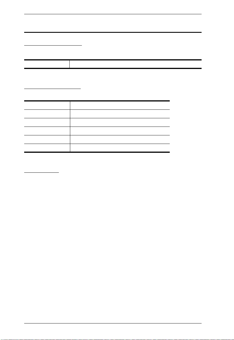
The Serial Console Server Series of advanced console servers integrates
cutting edge technologies with secure enterprise communications. Models
offer IT professionals and network operations center (NOC) personnel the
ability to perform secure, remote data management and out-of-band
management of IT assets from anywhere in the world. Available in 8, 16, 32
and 48-port models, the console servers fit in 1U of rack space with dual AC
and DC (SN0108AD / SN0116AD / SN0132D / SN0148D) power optio ns.
With their comprehensive serial management features, the console servers help
maximize IT asset productivity, provide scalability and reduce operational
costs.
Model Ports Power LAN Ports USB / LUC
SN0108A 8 Dual / AC Dual 3 / 1
SN0108AD 8 Terminal / DC Dual 3 / 1
SN0116A 16 Dual / AC Dual 3 / 1
SN0116AD 16 Terminal / DC Dual 3 / 1
SN0132 32 Dual / AC Dual 3 / 1
SN0132D 32 Terminal / DC Dual 3 / 1
SN0148 48 Dual / AC Dual 3 / 1
SN0148D 48 Terminal / DC Dual 3 / 1
SN9108 8 Single / AC Single None
SN9116 16 Single / AC Single None
The SN0108A / SN0108AD / SN0116A / SN0116AD / SN0132 / SN0132D /
SN0148 / SN0148D / SN9108 / SN9116 are console servers that provide
remote serial access to up to 8 (SN0108A / SN0108AD / SN9108), 16
(SN0116A / SN0116AD / SN9116), 32 (SN0132 / SN0132D) or 48 (SN0148 /
SN0148D) servers or other serial IT devices (hubs, routers, power management
devices, etc.), via a Telnet or SSH TCP/IP connection. Serial Console Server
devices can work in tandem with other remote management products – such as
PN5/PN7 and PN0108 Power over the NET™ devices – to provide convenient,
reliable, and effective, remote data center device management.
1

Serial Console Server User Manual
The SN0108A / SN0108AD / SN0116A / SN0116AD / SN0132 / SN0132D /
SN0148 / SN0148D / SN9108 / SN9116 also offer software features to meet
the most demanding data center management applications. Features include
multilingual Web user interface (UI), versatile operation modes, Serial Viewer
with a comprehensive set of functions, and power management integration.
This enables administrators to have complete control of remote serial devices
to shorten mean-time-to-recover (MTTR). Furthermore, to comply with
existing data center network access policies, the Serial Console Server
provides customizable multiple access levels for secure management.
Providing a complete solution for secure remote control, the Serial Console
Server also features 3rd party authentication, data encryption during
transmission, access list, data logging, and event monitoring and notification.
In addition, the console servers support next generation network standards such
as Internet Protocol version 6 (IPv6).
Installation is fast and easy: plugging cables into their appropriate ports is all
that is entailed. A choice of browser based GUI, Telnet (SSH), laptop USB
console (SN0108A / SN0108AD / SN0116A / SN0116AD / SN0132 /
SN0132D / SN0148 / SN0148D) and VT console terminal sessions make
configuration and operation smooth and convenient.
The SN0108A / SN0108AD / SN0116A / SN0116AD / SN0132 / SN0132D /
SN0148 / SN0148D / SN9108 / SN9116's firmware is upgradeable, so you can
stay current with the latest improvements simply by downloading updates from
our website. With its advanced features and ease of operation, the Serial
Console Server is the most convenient, most reliable, and most cost effective
way to centrally manage your remote, serially connected, IT products.
2

Chapter 1. Introduction
Features
System Accessibility and Availability
Remote serial access for up to 8/16/32/48 servers or other serial
devices
Secure in-band and out-of-band network access to serial consoles
In-band access of Ethernet
Browser access with an intuitive GUI
Terminal-based access with a menu-driven UI
Out-of-band access of dial-up modem
Modem dial-in/dial-back/dial-out
SN0108A / SN0108AD / SN0116A / SN0116AD / SN0132 / SN0132D
/ SN0148 / SN0148D Include:
Front access USB ports for USB storage or for USB-based PC
cards
Laptop USB Console (LUC) port for extra local console access
via laptop computer
Dual Ethernet ports for redundancy or for dual IP addresses
access
Dual power supply
Serial Console Management
Convenient and simple access via browser or Telnet/SSH client
Port access via Telnet/SSH client and third-party client such as PuTTY
Direct port access from Telnet client – bypassing login to SN
Convenient port access via the applet serial viewer from SN Web GUI
Selectable Telnet or SSH for the serial viewer
Selectable ActiveX or Java for the serial viewer
Comprehensive viewer function – copy/paste, logging, data import,
Macro, broadcast and Message Board
Sun Solaris ready – Sun “break-safe”
Alert String
Command filter
Data buffering
Multiple users simultaneously access to the same port – up to 16
connections per port
3

Serial Console Server User Manual
Selectable mode for multiple simultaneous access – Exclusive/Occupy/
Share mode
Integrated with Power Over the NET™ products for port and power
outlet association
Security
SSH and SSL (TLS v1.0 / TLS v1.1 / TLS v1.2) support
Secure login from browser with TLS 1.2 data encryption and RSA
2048-bit certificates
Configurable user permissions for port access and control
Configurable group permission for port access and control
Local and remote authentication and logging
Third-party authentication supports RADIUS, TACACS+, LDAP/AD,
and Kerberos
IP filtering and MAC filtering
System Management
System configuration via Web browser of HTTP/HTTPS, Telnet/SSH
client and local console
Up to 64 user accounts – allow 64 concurrent logins to access the
system
System log and event logging
Comprehensive logging and event notification
ATEN Log server and Syslog server
SNMP agent
Event notification – supports notification of SMTP email, SNMP Trap,
and SMS (with additional mobile device)
Pure Web management interface (HTTP/HTTPS), no Java run-time
environment required
Backup/restore system configuration
Firmware upgradeable
Multi-browser support – Internet Explorer, Chrome, Firefox, Safari,
Opera, Mozilla
Customizable global time zone
NTP for time server synchronization
DHCP for dynamic IP address assignment
4

Chapter 1. Introduction
IPv6 support
Integrated with CC2000 for centralized data center management
Supports AC or DC operation
Serial Device Management
Versatile serial operation modes – supports Real COM, TCP Server,
TCP Client, UDP, Serial Tunnel and Virtual Modem
128-bit/256-bit SSL (TLS v1.0 / TLS v1.1 / TLS v1.2) encryption for
Real COM, TCP Server, TCP Client, Serial T unnel and Virtual Modem
Virtual Terminal support (VT52, VT100, VT220, VT320)
Real COM driver for Windows 2000/XP/Vista/7 and Windows Server
2003/2008
Built-in 15KV ESD protection for serial ports
Real TTY driver for Linux
Fixed TTY driver for UNIX
Language
Multi-language web-based GUI – available for Japanese, Korean,
German, Russian, Simplified Chinese and Traditional Chinese
5

Serial Console Server User Manual
Requirements
The devices that connect to the Serial Console Server must support the
following serial protocol:
RS-232 (protocol or terminal operations)
For Console Management operating mode; Telnet/SSH client, a third party
client such as PuTTY, or web browser must be installed
For the browser-based WinClient ActiveX, SNViewer for console
operating mode, and DirectX 8 must be present, and at least 2MB of
memory must be available after installation.
For the browser-based Java Applet Viewer SNViewer for console
management operating mode, Sun's Java 2 JRE 1.4.2 or higher must be
installed, and at least 2MB of memory must be available after installation.
Java is available for free download from the Sun Java website:
http://java.sun.com
The Virtual COM port driver (Real COM port) support requires Windows
2000 or higher.
Under Vista (32-bit version), only the administrator can install the Virtual
Port Management Utility – ordinary users can only operate the mapped
Real COM ports.
The current Linux TTY driver supports kernels 2.2, 2.4, 2.6 (up to 2.6.39),
and 3.1 (up to 3.1.5-23).
The Fixed TTY driver for UNIX supports: Unix, OpenServer; Unix Ware
7, SVR 5; Unix Ware 2.1, SVR 4.2; QNX 4.25, QNX 6; FreeBSD; Solaris
10; AIX 5.x; and HP-UX 11i.
For the Log Server, you must have the Microsoft Jet OLEDB 4.0 or higher
driver installed.
6
Chapter 1. Introduction
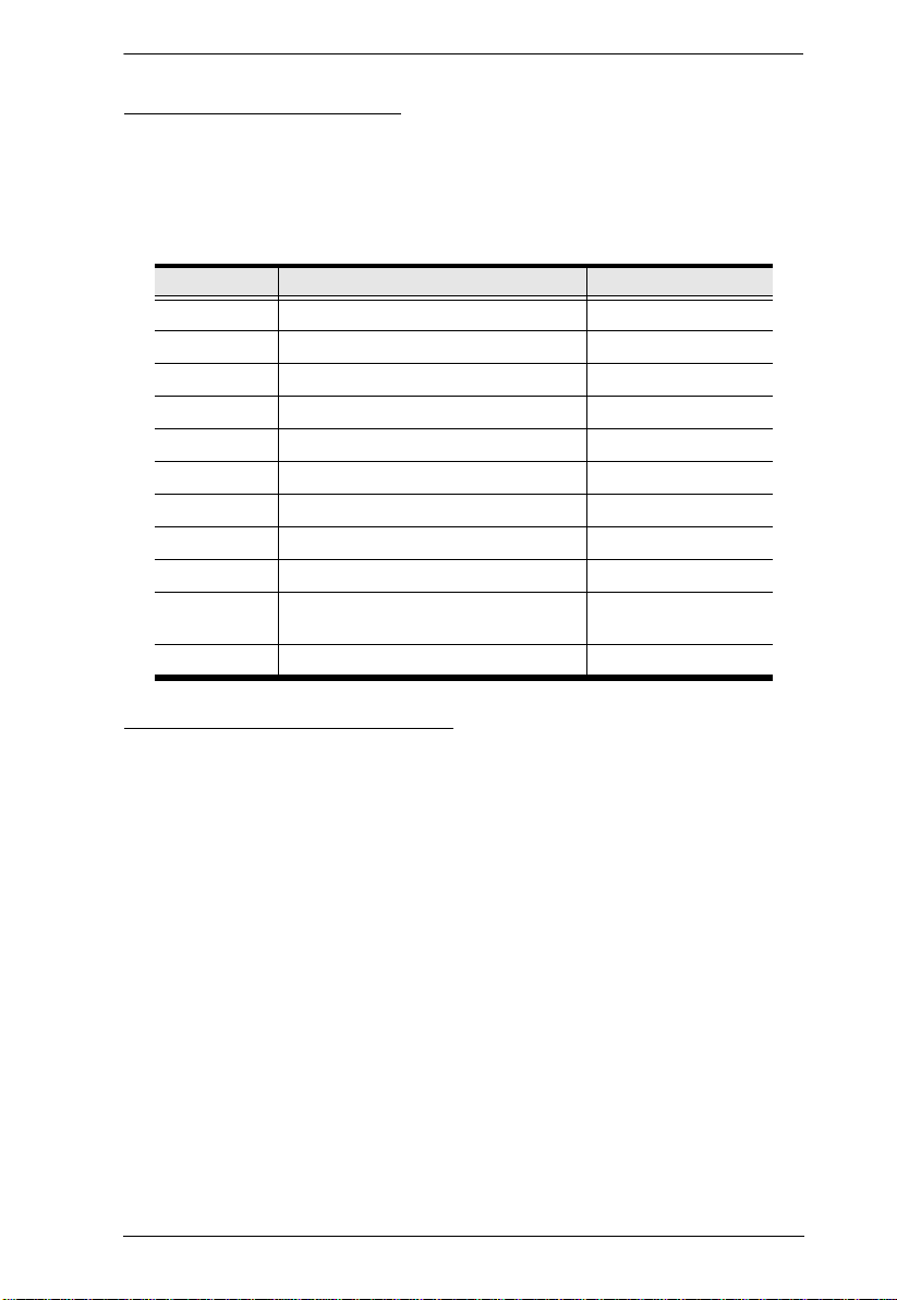
RJ-45 to Serial Adapters
Cat 5e (or higher) cable is required to connect the Serial Console Server to
the RJ-45 Serial Adapters (see page 27).
The various RJ-45 to Serial Adapters offered by ATEN are shown in the
table, below:
Model Connector Interface
SA0141 RJ-45 to DB9-F DTE to DTE
SA0142 RJ-45 to DB9-M DTE to DCE
SA0143 RJ-45 to DB25-F DTE to DTE
SA0144 RJ-45 to DB25-M DTE to DCE
SA0145 RJ-45 to DB9-M DTE to DTE
SA0146 RJ-45 to DB9-F DTE to DCE
SA0147 RJ-45 to DB25-M DTE to DTE
SA0148 RJ-45 to DB25-F DTE to DCE
SA0149 RJ-45 to DB9-M PN0108 to PN7/PN5
SA0150 RJ-45 to DB9-F PN7/PN5/SN to
SA0151 DB9-F to RJ-45 PC to PN7/PN5
PN0108
RJ-45 to RJ-45 Cat 5e Cables
For serial devices with DB9 or DB25 connectors, use standard straight-
through cables.
For serial devices with RJ-45 connectors, use rollover cable or specialized
pinout cable.
7
Serial Console Server User Manual
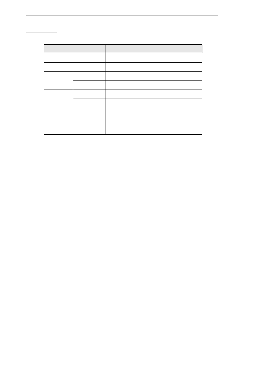
Browsers
Supported browsers for logging into the device include the following:
Browser Version
IE 6 and higher
Chrome 8.0 and higher
Firefox Windows 3.5 and higher
Linux 3.0 and higher
Safari Windows 4.0 and hi gher
Mac 3.1 and higher
Opera 10.0 and higher
Mozilla Windows 1.7 and higher
SUN
1.7 and higher
8
Components
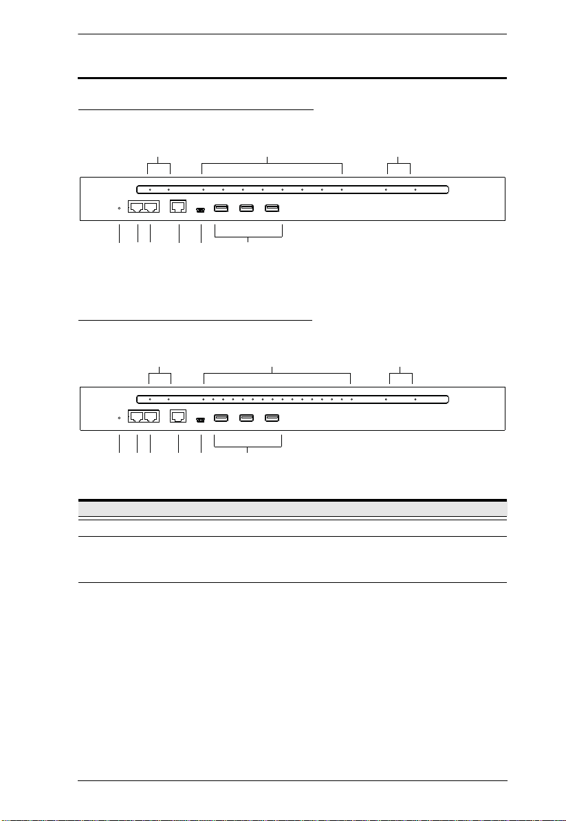
SN0108A / SN0108AD Front View
Chapter 1. Introduction
1 2
56
4789
3
SN0116A / SN0116AD Front View
1 2
4789
56
No. Component Description
1 Power LEDs Lights when the unit is powered up and ready to operate.
2 Port LEDs The Port
Flashes Green: Active – data is being transmitted through
the port
3 LAN LEDs Primary and Secondary 10/100/1000 Mbps LAN LEDs.
RED: 10 Mbps
RED + GREEN (ORANGE): 100 Mbps
GREEN: 1000 Mbps
Flashes to indicate that the Serial Console Server is being
accessed over the LAN.
3
9

Serial Console Server User Manual
No. Component Description
4Reset SwitchNote: This switch is recessed and must be pushed with a small
object such as the end of a paper clip, or a ballpoint pen.
Pressing and releasing this switch when the unit is running
performs a system reset.
Pressing and holding this switch in for more than three
seconds when the unit is running resets its configuration to
the factory default settings.
Note: This does not clear User Account information.
See Clear Login Information, page 151, for
information on clearing user account information.
Pressing and holding this switch while powering on the
switch returns the unit to its factory default firmware level,
rather than the firmware version that the switch has been
upgraded to. This allows you to recover from a f ailed
firmware upgrade and gives you the opportunity to try
upgrading the firmware again.
Note: This operation should only be performed in the event
of a firmware upgrade failure that results in the device
becoming inoperable.
5 PON Port This connector is provided for a Power over the Net™ (PON)
unit which allows servers attached to the Serial Console Server
to be booted remotely. See Serial Console Server Installation,
page 27, step 5 for installation details.
Contact your dealer for more information regarding PON units.
6 Modem Port For dial in connection should the unit be unavailable over the
7 Local Console
Port
8 Laptop USB
Console Port
9 USB Ports These three Type A female USB ports can be used to connect
network. See Serial Console Server Installation, page 27, step
6 for installation details.
This RJ45 port allows for local administration and access
through a serial terminal connection to a computer. An SA0141
(DTE to DTE) adapter (included in the package) is required for
this connection.
This mini-USB port allows a PC or laptop to be connected for
local access and control. Connect to a PC or laptop to
automatically launch a terminal emulator to access the SN text
menu.
USB devices, such as USB storage devices (pen drive / hard
drive), USB hubs and USB LAN cards.
10
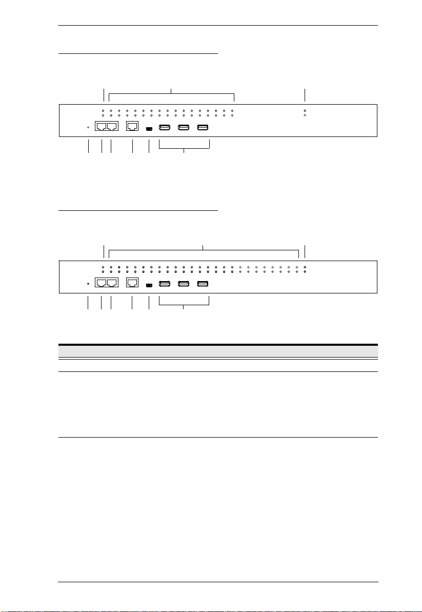
SN0132 / SN0132D Front View
1
2
4789
3
56
1
2
4789
3
56
SN0148 / SN0148D Front View
Chapter 1. Introduction
No. Component Description
1 Power LEDs Lights when the unit is powered up and ready to operate.
2 Port LEDs The Port LEDs provide status information about their
corresponding serial ports.
Lights Green: Online – the serial device attached to the port
is powered on and ready.
Flashes Green: Active – data is being transmitted through
the port
3 LAN LEDs Primary and Secondary 10/100/1000 Mbps LAN LEDs.
RED: 10 Mbps
RED + GREEN (ORANGE): 100 Mbps
GREEN: 1000 Mbps
Flashes to indicate that the Serial Console Server is being
accessed over the LAN.
11

Serial Console Server User Manual
No. Component Description
4Reset SwitchNote: This switch is recessed and must be pushed with a small
object such as the end of a paper clip, or a ballpoint pen.
Pressing and releasing this switch when the unit is running
performs a system reset.
Pressing and holding this switch in for more than three
seconds when the unit is running resets its configuration to
the factory default settings.
Note: This does not clear User Account information.
See Clear Login Information, page 151, for
information on clearing user account information.
Pressing and holding this switch while powering on the
switch returns the unit to its factory default firmware level,
rather than the firmware version that the switch has been
upgraded to. This allows you to recover from a failed
firmware upgrade and gives you the opportunity to try
upgrading the firmware again.
Note: This operation should only be performed in the event
of a firmware upgrade failure that results in the device
becoming inoperable.
5 PON Port This connector is provided for a Power over the Net™ (PON)
unit which allows servers attached to the Serial Console Server
to be booted remotely. See Serial Console Server Installation,
page 27, step 5 for installation details.
Contact your dealer for more information regarding PON units.
6 Modem Port For dial in connection should the unit be unavailable over the
7 Local Console
Port
8 Laptop USB
Console Port
9 USB Ports These three Type A female USB ports can be used to connect
network. See Serial Console Server Installation, page 27, step
6 for installation details.
This RJ45 port allows for local administration and access
through a serial terminal connection to a computer. An SA0141
(DTE to DTE) adapter (included in the package) is required for
this connection.
This mini-USB port allows a PC or laptop to be connected for
local access and control. Connect to a PC or laptop to
automatically launch a terminal emulator to access the SN text
menu.
USB devices, such as USB storage devices (pen drive / hard
drive), USB hubs and USB LAN cards.
12
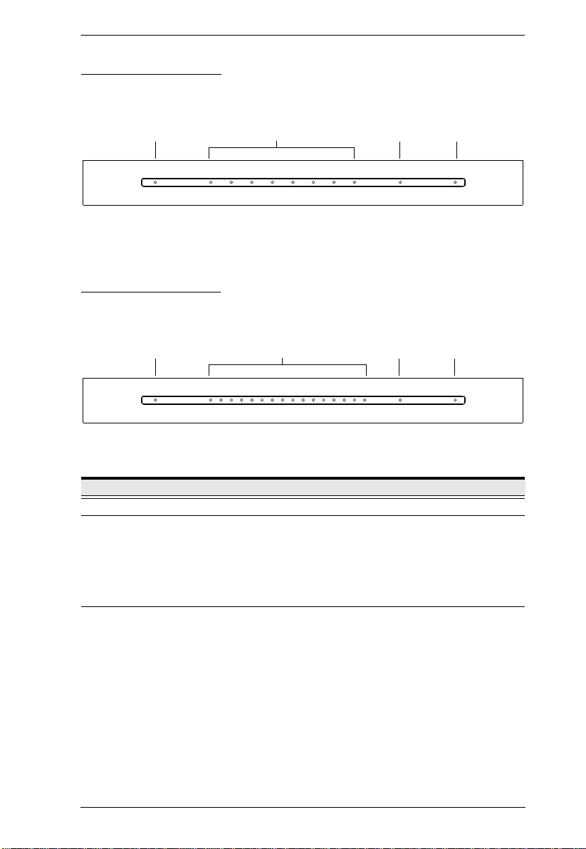
SN9108 Front View
1 243
1 243
SN9116 Front View
Chapter 1. Introduction
No. Component Description
1 Power LED Lights when the unit is powered up and ready to operate.
2 Port LEDs The Port LEDs provide status information about their
corresponding serial ports.
Lights Green: Online – the serial device attached to the port
is powered on and ready.
Flashes Green: Active – data is being transmitted through
the port
3 LAN LED Primary and Secondary 10/100/1000 Mbps LAN LEDs.
RED: 10 Mbps
RED + GREEN (ORANGE): 100 Mbps
GREEN: 1000 Mbps
Flashes to indicate that the Serial Console Server is being
accessed over the LAN.
13

Serial Console Server User Manual
No. Component Description
4Reset SwitchNote: This switch is recessed and must be pushed with a small
object such as the end of a paper clip, or a ballpoint pen.
Pressing and releasing this switch when the unit is running
performs a system reset.
Pressing and holding this switch in for more than three
seconds when the unit is running resets its configuration to
the factory default settings.
Note: This does not clear User Account information.
See Clear Login Information, page 151, for
information on clearing user account information.
Pressing and holding this switch while powering on the
switch returns the unit to its factory default firmware level,
rather than the firmware version that the switch has been
upgraded to. This allows you to recover from a failed
firmware upgrade and gives you the opportunity to try
upgrading the firmware again.
Note: This operation should only be performed in the event
of a firmware upgrade failure that results in the device
becoming inoperable.
14
 Loading...