

ATEN PE6208AV, PE8208AV User Manual
eco PDU PE Series
PE6208AV / PE8208AV
Power Distribution Unit
User Manual
www.aten.com

PE6208AV / PE8208AV User Manual
EMC Information
FEDERAL COMMUNICATIONS COMMISSION INTERFERENCE
STATEMENT: This equipment has been tested and found to comply with the
limits for a Class A digital device, pursuant to Part 15 of the FCC Rules. These
limits are designed to provide reasonable protection against harmful
interference when the equipment is operated in a commercial environment.
This equipment generates, uses, and can radiate radio frequency energy and, if
not installed and used in accordance with the instruction manual, may cause
harmful interference to radio communications. Operation of this equipment in
a residential area is likely to cause harmful interference in which case the user
will be required to correct the interference at his own expense.
The device complies with Part 15 of the FCC Rules. Operation is subject to the
following two conditions: (1) this device may not cause harmful interference,
and (2) this device must accept any interference received, including
interference that may cause undesired operation.
FCC Caution: Any changes or modifications not expressly approved by the
party responsible for compliance could void the user's authority to operate this
equipment.
CE Warning: This is a class A product. In a domestic environment this
product may cause radio interference in which case the user may be required to
take adequate measures.
KCC Statement
유선 제품용 / A 급 기기 ( 업무용 방송 통신 기기 )
이 기기는 업무용 (A 급 ) 전자파적합기기로서 판매자 또는 사용자는 이
점을 주의하시기 바라며 , 가정 외의 지역에서 사용하는 것을 목적으로
합니다 .
RoHS
This product is RoHS compliant.
ii

eco PDU PE Series User Manual
User Information
Online Registration
Be sure to register your product at our online support center:
International http://eservice.aten.com
Telephone Support
For telephone support, call this number:
International 886-2-8692-6959
China 86-400-810-0-810
Japan 81-3-5615-5811
Korea 82-2-467-6789
North America 1-888-999-ATEN ext 4988
United Kingdom 44-8-4481-58923
User Notice
All information, documentation, and specifications contained in this manual are subject
to change without prior notification by the manufacturer. The manufacturer makes no
representations or warranties, either expressed or implied, with respect to the contents
hereof and specifically disclaims any warranties as to merchantability or fitness for any
particular purpose. Any of the manufacturer's software described in this manual is sold
or licensed as is. Should the programs prove defective following their purchase, the
buyer (and not the manufacturer, its distributor, or its dealer), assumes the entire cost of
all necessary servicing, repair and any incidental or consequential damages resulting
from any defect in the software.
The manufacturer of this system is not responsible for any radio and/or TV interference
caused by unauthorized modifications to this device. It is the responsibility of the user
to correct such interference.
The manufacturer is not responsible for any damage incurred in the operation of this
system if the correct operational voltage setting was not selected prior to operation.
PLEASE VERIFY THAT THE VOLTAGE SETTING IS CORRECT BEFORE USE.
If any bodily injury or property damage with respect to operation of the product results
from users not having installed the product in accordance with the instructions provided
in the product’s user manual, or the product is used in an environment with a current
load over the designed specifications of the product, ATEN is not liable for any loss or
damage.
iii

PE6208AV / PE8208AV User Manual
Set the maximum permissible breaker protection in the building circuitry to the
current rating specified on the rating plate. Observe all national regulations and
safety codes as well as deviations for breakers.
Only connect the PE Device to a grounded power outlet or a grounded system!
Make sure that the total current input of the connected systems does not exceed
the current rating specified on the rating plate of the PE Device.
There is a risk of explosion if the battery is replaced with an incorrect type.
Dispose of used batteries according to the relevant instructions.
PE Device Safety Notice
Consignes de sècuritè relatives à l’unitè PE
Installez sur le circuit du bâtiment des disjoncteurs permettant d’assurer la
protection maximale autorisée, en respectant le courant nominal spécifié sur la
plaque signalétique. Veuillez respecter l’ensemble des réglementations nationales
en vigueur et des codes de sécurité ainsi que les déviations recommandèes pour les
disjoncteurs.
Ne connectez l’unité PE qu’à une prise de courant avec borne de terre ou à un
système mis à la terre!
Assurez-vous que le courant d’entrée total des systèmes connectés ne dépasse pas
le courant nominal spécifié sur la plaque signalétique de l’unité PE.
Il existe un risque d’explosion si la batterie est remplacée par une batterie de type
incorrect. Jetez les batteries usagées en respectant les instructions adequates.
iv

eco PDU PE Series User Manual
Copyright © 201 ATEN® International Co., Ltd.
Date Published: 2018-02-22
NRGence and the NRGence logo are registered trademarks of ATEN International Co., Ltd. All rights reserved.
All other brand names and trademarks are the registered property of their respective owners.
Package Contents
The eco PDU PE Series package consists of:
1 PE6208AV / PE8208AV Power Distribution Unit
1 Power Cord
1 RJ-45 Cable
4 Cable Ties
1 Footpad Set
1 Mounting Kit
1 User Instructions*
Check to make sure that all of the components are present and in good order.
If anything is missing, or was damaged in shipping, contact your dealer.
Read this manual thoroughly and follow the installation and operation
procedures carefully to prevent any damage to the switch or to any other
devices on the eco PDU installation.
* Features may have been added to the eco PDU since this manual was
published. Please visit our website to download the most up-to-date version.
v

PE6208AV / PE8208AV User Manual
Contents
EMC Information . . . . . . . . . . . . . . . . . . . . . . . . . . . . . . . . . . . . . . . . . . . . . ii
RoHS . . . . . . . . . . . . . . . . . . . . . . . . . . . . . . . . . . . . . . . . . . . . . . . . . . . . . ii
User Information. . . . . . . . . . . . . . . . . . . . . . . . . . . . . . . . . . . . . . . . . . . . .iii
Online Registration . . . . . . . . . . . . . . . . . . . . . . . . . . . . . . . . . . . . . . . .iii
Telephone Support . . . . . . . . . . . . . . . . . . . . . . . . . . . . . . . . . . . . . . . .iii
User Notice . . . . . . . . . . . . . . . . . . . . . . . . . . . . . . . . . . . . . . . . . . . . . .iii
PE Device Safety Notice. . . . . . . . . . . . . . . . . . . . . . . . . . . . . . . . . . . .iv
Consignes de sècuritè relatives à l’unitè PE. . . . . . . . . . . . . . . . . . . . .iv
Package Contents . . . . . . . . . . . . . . . . . . . . . . . . . . . . . . . . . . . . . . . . . . . v
About This Manual . . . . . . . . . . . . . . . . . . . . . . . . . . . . . . . . . . . . . . . . . . .ix
Conventions . . . . . . . . . . . . . . . . . . . . . . . . . . . . . . . . . . . . . . . . . . . . . x
Product Information . . . . . . . . . . . . . . . . . . . . . . . . . . . . . . . . . . . . . . . . . . x
Chapter 1.
Introduction
Overview. . . . . . . . . . . . . . . . . . . . . . . . . . . . . . . . . . . . . . . . . . . . . . . . . . .1
eco PDU Comparison Chart . . . . . . . . . . . . . . . . . . . . . . . . . . . . . . . . .3
Features . . . . . . . . . . . . . . . . . . . . . . . . . . . . . . . . . . . . . . . . . . . . . . . . . . .4
Connections . . . . . . . . . . . . . . . . . . . . . . . . . . . . . . . . . . . . . . . . . . . . .4
Metering . . . . . . . . . . . . . . . . . . . . . . . . . . . . . . . . . . . . . . . . . . . . . . . .4
Outlet Switch Control . . . . . . . . . . . . . . . . . . . . . . . . . . . . . . . . . . . . . .4
Requirements . . . . . . . . . . . . . . . . . . . . . . . . . . . . . . . . . . . . . . . . . . . . . . .5
Optional Accessories . . . . . . . . . . . . . . . . . . . . . . . . . . . . . . . . . . . . . . . . .6
Sensors. . . . . . . . . . . . . . . . . . . . . . . . . . . . . . . . . . . . . . . . . . . . . . . . . 6
Cable Holders . . . . . . . . . . . . . . . . . . . . . . . . . . . . . . . . . . . . . . . . . . . .6
Components . . . . . . . . . . . . . . . . . . . . . . . . . . . . . . . . . . . . . . . . . . . . . . . .7
PE6208AV / PE8208AV Front View . . . . . . . . . . . . . . . . . . . . . . . . . . . 7
PE6208AV / PE8208AV Rear View . . . . . . . . . . . . . . . . . . . . . . . . . . . 9
Chapter 2.
Hardware Setup
Before You Begin . . . . . . . . . . . . . . . . . . . . . . . . . . . . . . . . . . . . . . . . . . . 11
Stacking and Rack Mounting . . . . . . . . . . . . . . . . . . . . . . . . . . . . . . . . . .11
Stacking . . . . . . . . . . . . . . . . . . . . . . . . . . . . . . . . . . . . . . . . . . . . . . . 11
Rack Mounting . . . . . . . . . . . . . . . . . . . . . . . . . . . . . . . . . . . . . . . . . . 13
Installation. . . . . . . . . . . . . . . . . . . . . . . . . . . . . . . . . . . . . . . . . . . . . . . . .15
Securing the Cables . . . . . . . . . . . . . . . . . . . . . . . . . . . . . . . . . . . . . .17
Securing the Sensors . . . . . . . . . . . . . . . . . . . . . . . . . . . . . . . . . . . . .18
Chapter 3.
Basic Operation and
First Time Setup
Operation Methods. . . . . . . . . . . . . . . . . . . . . . . . . . . . . . . . . . . . . . . . . . 19
Browser. . . . . . . . . . . . . . . . . . . . . . . . . . . . . . . . . . . . . . . . . . . . . . . . 19
vi

eco PDU PE Series User Manual
eco Sensors . . . . . . . . . . . . . . . . . . . . . . . . . . . . . . . . . . . . . . . . . . . .19
SNMP . . . . . . . . . . . . . . . . . . . . . . . . . . . . . . . . . . . . . . . . . . . . . . . . .19
First Time Setup . . . . . . . . . . . . . . . . . . . . . . . . . . . . . . . . . . . . . . . . . . . .20
Network Configuration. . . . . . . . . . . . . . . . . . . . . . . . . . . . . . . . . . . . .21
Changing the Administrator Login. . . . . . . . . . . . . . . . . . . . . . . . . . . .22
Moving On. . . . . . . . . . . . . . . . . . . . . . . . . . . . . . . . . . . . . . . . . . . . . . . . .22
Chapter 4.
Browser Operation
Logging In . . . . . . . . . . . . . . . . . . . . . . . . . . . . . . . . . . . . . . . . . . . . . . . . .23
The eco PDU Main Page . . . . . . . . . . . . . . . . . . . . . . . . . . . . . . . . . . . . .24
Page Components. . . . . . . . . . . . . . . . . . . . . . . . . . . . . . . . . . . . . . . .24
Energy. . . . . . . . . . . . . . . . . . . . . . . . . . . . . . . . . . . . . . . . . . . . . . . . . . . .26
Connections . . . . . . . . . . . . . . . . . . . . . . . . . . . . . . . . . . . . . . . . . . . .26
Configuration (PE6208AV) . . . . . . . . . . . . . . . . . . . . . . . . . . . . . . . . .30
Configuration (PE8208AV) . . . . . . . . . . . . . . . . . . . . . . . . . . . . . . . . .32
User. . . . . . . . . . . . . . . . . . . . . . . . . . . . . . . . . . . . . . . . . . . . . . . . . . . . . .38
Administrator Information . . . . . . . . . . . . . . . . . . . . . . . . . . . . . . . . . .38
User Information . . . . . . . . . . . . . . . . . . . . . . . . . . . . . . . . . . . . . . . . .39
Log . . . . . . . . . . . . . . . . . . . . . . . . . . . . . . . . . . . . . . . . . . . . . . . . . . . . . .41
The System Log Event List . . . . . . . . . . . . . . . . . . . . . . . . . . . . . . . . .41
Notification Settings. . . . . . . . . . . . . . . . . . . . . . . . . . . . . . . . . . . . . . .42
Setup. . . . . . . . . . . . . . . . . . . . . . . . . . . . . . . . . . . . . . . . . . . . . . . . . . . . .43
Device Configuration. . . . . . . . . . . . . . . . . . . . . . . . . . . . . . . . . . . . . .43
Date/Time . . . . . . . . . . . . . . . . . . . . . . . . . . . . . . . . . . . . . . . . . . . . . .49
Security . . . . . . . . . . . . . . . . . . . . . . . . . . . . . . . . . . . . . . . . . . . . . . . .51
Login Failures . . . . . . . . . . . . . . . . . . . . . . . . . . . . . . . . . . . . . . . . . . .51
Working Mode . . . . . . . . . . . . . . . . . . . . . . . . . . . . . . . . . . . . . . . . . . .51
Session Timeout . . . . . . . . . . . . . . . . . . . . . . . . . . . . . . . . . . . . . . . . .51
Account Policy. . . . . . . . . . . . . . . . . . . . . . . . . . . . . . . . . . . . . . . . . . .52
Login String / IP Filter / Mac Filter. . . . . . . . . . . . . . . . . . . . . . . . . . . .53
Authentication & Authorization . . . . . . . . . . . . . . . . . . . . . . . . . . . . . .56
Private Certificate . . . . . . . . . . . . . . . . . . . . . . . . . . . . . . . . . . . . . . . .57
PDU. . . . . . . . . . . . . . . . . . . . . . . . . . . . . . . . . . . . . . . . . . . . . . . . . . . . . .59
Firmware File. . . . . . . . . . . . . . . . . . . . . . . . . . . . . . . . . . . . . . . . . . . .59
Backup/Restore. . . . . . . . . . . . . . . . . . . . . . . . . . . . . . . . . . . . . . . . . .61
Chapter 5.
RS-232 / Telnet Commands
Remote Terminal Operations . . . . . . . . . . . . . . . . . . . . . . . . . . . . . . . . . .63
Telnet . . . . . . . . . . . . . . . . . . . . . . . . . . . . . . . . . . . . . . . . . . . . . . . . .63
RS-232 Serial Control . . . . . . . . . . . . . . . . . . . . . . . . . . . . . . . . . . . . .65
Commands . . . . . . . . . . . . . . . . . . . . . . . . . . . . . . . . . . . . . . . . . . . . . . . .66
Verification. . . . . . . . . . . . . . . . . . . . . . . . . . . . . . . . . . . . . . . . . . . . . .66
Read Outlet Status . . . . . . . . . . . . . . . . . . . . . . . . . . . . . . . . . . . . . . .67
Switch Outlet Status . . . . . . . . . . . . . . . . . . . . . . . . . . . . . . . . . . . . . .69
Read Power Value . . . . . . . . . . . . . . . . . . . . . . . . . . . . . . . . . . . . . . .71
vii

PE6208AV / PE8208AV User Manual
Read Environmental Value . . . . . . . . . . . . . . . . . . . . . . . . . . . . . . . . . 73
Close Telnet Session . . . . . . . . . . . . . . . . . . . . . . . . . . . . . . . . . . . . . 74
Appendix
Safety Instructions . . . . . . . . . . . . . . . . . . . . . . . . . . . . . . . . . . . . . . . . . .75
General . . . . . . . . . . . . . . . . . . . . . . . . . . . . . . . . . . . . . . . . . . . . . . . . 75
Consignes de sécurité . . . . . . . . . . . . . . . . . . . . . . . . . . . . . . . . . . . . . . .78
Général . . . . . . . . . . . . . . . . . . . . . . . . . . . . . . . . . . . . . . . . . . . . . . . . 78
Rack Mounting . . . . . . . . . . . . . . . . . . . . . . . . . . . . . . . . . . . . . . . . . . 81
The eco PDU’s Main Power Cord. . . . . . . . . . . . . . . . . . . . . . . . . . . .81
Securing the Power Cables. . . . . . . . . . . . . . . . . . . . . . . . . . . . . . . . .81
Montage sur bâti . . . . . . . . . . . . . . . . . . . . . . . . . . . . . . . . . . . . . . . . .82
Le cordon d’alimentation principale de l’unité d’alimentation éco . . . . 82
Fixation des câbles d’alimentation . . . . . . . . . . . . . . . . . . . . . . . . . . . 82
Technical Support. . . . . . . . . . . . . . . . . . . . . . . . . . . . . . . . . . . . . . . . . . .84
International . . . . . . . . . . . . . . . . . . . . . . . . . . . . . . . . . . . . . . . . . . . .84
North America. . . . . . . . . . . . . . . . . . . . . . . . . . . . . . . . . . . . . . . . . . .84
IP Address Determination. . . . . . . . . . . . . . . . . . . . . . . . . . . . . . . . . . . . . 85
Specifications . . . . . . . . . . . . . . . . . . . . . . . . . . . . . . . . . . . . . . . . . . . . . . 87
PE6208AV(B) / PE6208AV(G) . . . . . . . . . . . . . . . . . . . . . . . . . . . . . . 87
PE6208AV(J) Japan . . . . . . . . . . . . . . . . . . . . . . . . . . . . . . . . . . . . . . 88
PE8208AV(B) / PE8208AV(G) . . . . . . . . . . . . . . . . . . . . . . . . . . . . . . 90
PE8208AV(J) Japan . . . . . . . . . . . . . . . . . . . . . . . . . . . . . . . . . . . . . . 91
Administrator Login Failure. . . . . . . . . . . . . . . . . . . . . . . . . . . . . . . . . . . .93
Limited Warranty. . . . . . . . . . . . . . . . . . . . . . . . . . . . . . . . . . . . . . . . . . . .94
viii

eco PDU PE Series User Manual
About This Manual
This User Manual is provided to help you get the most from your eco PDU
system. It covers all aspects of installation, configuration and operation. An
overview of the information found in the manual is provided below.
Chapter 1, Introduction, introduces you to the eco PDU system. Its purpose,
features and benefits are presented, and its front and back panel components
are described.
Chapter 2, Hardware Setup, provides step-by-step instructions for setting
up your installation.
Chapter 3, Basic Operation and First Time Setup, explains the
procedures that the Administrator employs to set up the eco PDU network
environment, and change the default username and password.
Chapter 4, Browser Operation, describes how to log in to the eco PDU with
an Internet browser, and explains the layout and components of the eco PDU’s
user interface.
Chapter 5, Telnet Access, describes how to connect to and access the eco
PDU’s using Telnet.
An Appendix, provides specifications and other technical information
regarding the eco PDU.
ix

PE6208AV / PE8208AV User Manual
Conventions
This manual uses the following conventions:
Monospaced Indicates text that you should key in.
[ ] Indicates keys you should press. For example, [Enter] means
to press the Enter key. If keys need to be chorded, they
appear together in the same bracket with a plus sign
between them: [Ctrl+Alt].
1. Numbered lists represent procedures with sequential steps.
♦ Bullet lists provide information, but do not involve sequential
steps.
→ Indicates selecting the option (on a menu or dialog box, for
example), that comes next. For example, Start
means to open the Start menu, and then select Run.
Indicates critical information.
→ Run
Product Information
For information about all NRGence products and how they can help you
connect without limits, visit NRGence on the Web or contact an NRGence
Authorized Reseller. Visit NRGence on the Web for a list of locations and
telephone numbers
International – http://www.aten.com
North America – http://www.aten-usa.com
x

Chapter 1
Introduction
Overview
ATEN has developed a new generation of green energy power distribution
units (PDUs) to effectively increase the efficiency of data center power usage
The NRGence PE6208AV / PE8208AV eco PDUs are intelligent PDUs that
contain 8 AC outlets with a detachable front panel for convenient rack
mounting and are available in various IEC or NEMA socket configurations.
They provide secure, centralized, intelligent, power management (power on,
off, cycle) of data center IT equipment (servers, storage systems, KVM
switches, network devices, serial data devices, etc.), as well as the ability to
monitor the center's health environment via sensors*. The basic characteristics
of each model are shown in the table on page 3.
NRGence eco PDUs offer remote power control combined with real-time
power measurement - allowing you to control and monitor the power status of
devices attached to the PDUs, either at the PDU and outlet level (PE8208AV)
or Bank level (PE6208AV), from practically any location via a TCP/IP
connection.
The power status of each outlet can be set individually, allowing users to switch
each device On/Off. The eco PDU also offers comprehensive power analysis
reports when used with the eco Sensors software which can separate
departments and locations, providing precise measurements of current,
voltage, power and watt-hour in a real-time display.
Installation and operation is fast and easy: plugging cables into their
appropriate ports and user-friendly browser-based configuration and
management is all that is entailed. Since the eco PDU firmware is upgradeable
over the Net, you can stay current with the latest functionality improvements
simply by downloading updates from our website as they become available.
NRGence eco PDU supports any 3rd party v3 SNMP Manager Software and
NRGence eco Sensors (eco PDU Manager Software). NRGence eco Sensors
provides you with an easy method for managing multiple devices, offering an
intuitive and user-friendly Graphical User Interface that allows you to
configure a PDU device and monitor power status of the equipment connected
to it.
(Continues on next page.)
1

PE6208AV / PE8208AV User Manual
(Continued from previous page.)
This series of ATEN eco PDUs have threshold alerts that can sound an alarm
and send SNMP trap or e-mail alerts when a threshold is exceeded. This feature
provides a faster response time to recover servers and other devices wh en the
outlets surpass thresholds set by you.
The PE6208AV / PE8208AV is an excellent fit for any ATEN VanCryst Pro
A/V or VK Control System installation. Using our cross platform solutions not
only provide you with the best performance but also utilize extra features
which bring you more confidence and more power to control.
With its advanced security features and ease of operation, the eco PDU is the
most convenient, most reliable, and most cost effective way to remotely
manage power access for multiple computer installations and allocate power
resources in the most efficient way possible.
Note: Sensors are optional accessories. A sensor-enabled installation is
required to generate a more complete energy-efficient data and chart.
Higher sensor installation density is helpful to generate more accurate
data. See Optional Accessories, page 6, for further information.
2

eco PDU Comparison Chart
Chapter 1. Introduction
Model Power Cord Outlets
PE6208AV-AT-B C20 to C19 IEC C13 PDU 15A (Max);
PE6208AV-AT-G NEMA 6-20P to
C19
PE6208AV-AT-J NEMA L6-20P to
C19
PE8208AV-AT-B C20 to C19 IEC C13 Outlet 15A (Max);
PE8208AV-AT-G NEMA 6-20P to
C19
PE8208AV-AT-J NEMA L6-20P to
C19
IEC C13 PDU 10A 16A
IEC C13 PDU 15A (Max);
IEC C13 Outlet 10A 16A
IEC C13 Outlet 15A (Max);
Monitor-
ing Level
Amps
Per Port Total
16A
12A (UL
de-rated)
16A
12A (UL
de-rated)
16A
12A (UL
de-rated)
16A
12A (UL
de-rated)
Note: For the complete specifications of individual m odels, please reference
Specifications, page 87.
3

PE6208AV / PE8208AV User Manual
Features
Connections
Space saving 1U rack mount design with rear mounting
Detachable front panel for convenient rack mounting
Support 10/100Mbit Ethernet Interface
Support TCP/IP, UDP, HTTP, HTTPS, SSL, DHCP, SMTP, ARP, NTP,
DNS, Auto Sense, Ping, SNMP V1, V2, and V3, Telnet
Support 2-level account/password security, IP/MAC filter, 128 bit SSL,
RADIUS
Support: eco Sensors, Browser (IE, Firefox, Chrome, Safari)
Additional functions available with ATEN VanCryst Pro A/V & VK
Control System installations
Metering
Bank level power metering and monitoring (PE6208AV); or PDU and
outlet level power metering and monitoring (PE8208A V)
Environment monitoring – supports external temperature/ temperature &
humidity sensors for rack temperature and humidity monitoring
Current, voltage, power, power dissipation, temperature, and humidity
metering and threshold level setting
Outlet Switch Control
Remote power outlet control (On/Off, Power Cycle) by individual outlets
and outlet groups
Outlet group support at the PDU level
Supports multiple power control methods – Wake on LAN, System After
AC Back, Kill the Power
Power-On sequencing – users can set the power-on sequence and delay
time for each outlet to allow equipment to be powered on in the correct
order
Local power on/off/reboot control via RS-232 port
Proactive Overload Protection (POP) – automatically powers off outlets
when current overloads to protect connected devices
4

Chapter 1. Introduction
Requirements
Browsers accessing the eco PDU unit must support SSL 128 bit
encryption.
For cold booting of attached computers, the computer's BIOS must
support Wake on LAN or System after AC Back.
For Safe Shutdown:
The computer must be running Windows (Windows 2000 or higher) or
Linux.
The Safe Shutdown program (available by download from our website
or on the software CD included), must be installed and running on the
computer.
5

PE6208AV / PE8208AV User Manual
Optional Accessories
Sensors
Sensors are optional accessories. You can use the eco PDU unit without
sensors. However, if you want to have complete energy management of an
instrumented data center with the use of the eco PDU, you would need to use
eco Sensors software and install 4 sensors for each of the racks to generate a
complete energy-efficient data and chart. Higher sensor installation density is
helpful to generate more accurate data. 8-port models have 2 sensor ports. In
this case, Sensor 1 needs to be installed at the intake of the rack and sensor 2
needs to be placed at the exhaust of IT equipment of the rack. A sensor-enabled
installation is required to generate a more complete energy-efficient data and
chart. Higher sensor installation density is helpful to generate more accurate
data. Available sensors are show in the table, below:
Sensor Part Number
Temperature EA1140
Temperature / Humidity EA1240
Differential Pressure / Temperature EA1340
Sensor Management
Sensors can be managed via the eco PDU’s built-in graphical user interface
(GUI) or with the NRGence eco Sensors software that can be downloaded from
the ATEN website. The download link can be found on the software CD
provided with the eco PDU package.
Cable Holders
Cable holders are optional accessories. For added safety, use ATEN Lok-UPlug cable holders to secure the cables from your attached devices in place on
the eco PDU unit. Use only the ATEN Lok-U-Plug cable holders that have
been specifically designed to work with the eco PDU. Using any other kind of
cable securing device could be highly dangerous.
Part Number Description
2X-EA07 Lok-U-Plug Cable Holder (10 pcs)
2X-EA08 Lok-U-Plug Installation Tool (4 pcs)
6
Chapter 1. Introduction
1
6
7
2 3
8 9
4
5
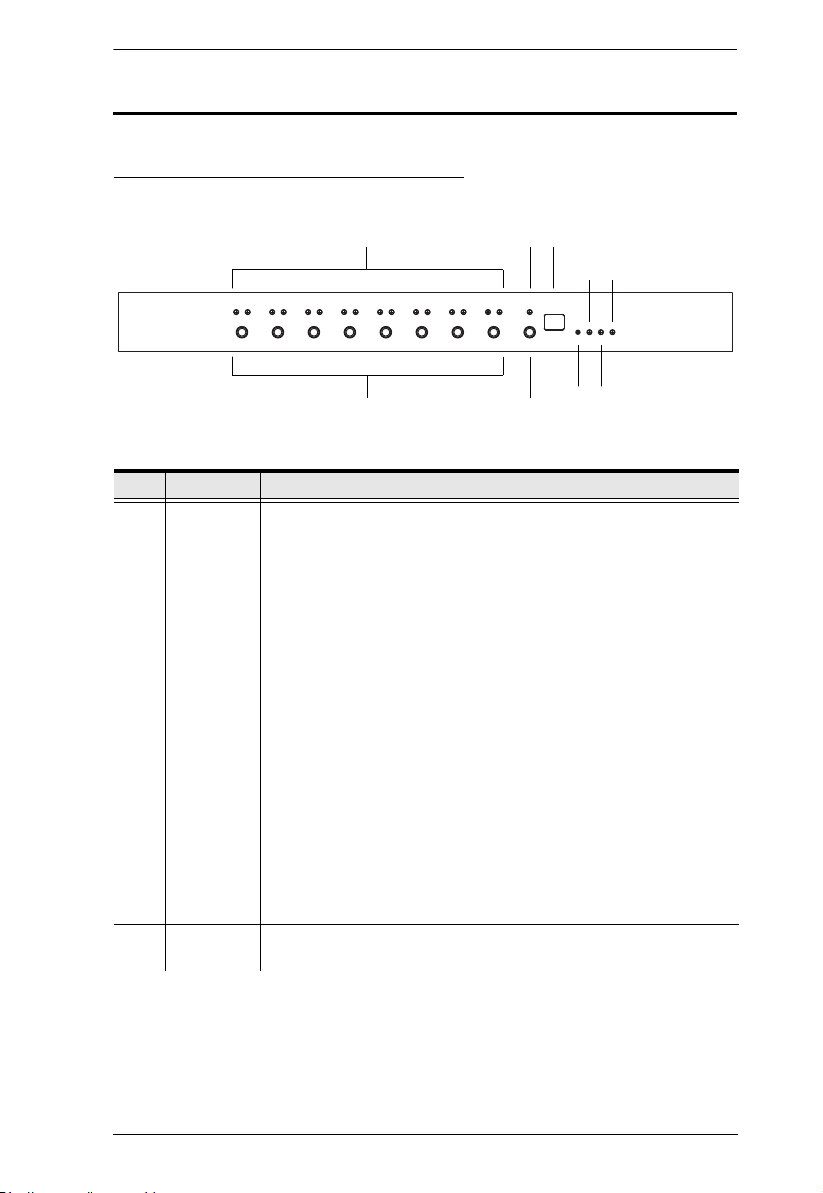
Components
PE6208AV / PE8208AV Front View
No. Item Description
1 Port LED The Port LEDs provide status information about their
2 Current
LED
corresponding AC outlet ports. There is one pair of LEDs for each
port. The one on the left is the Local LED; the one on the right is
the Power LED:
A Local LED lights GREEN to indicate that the device attached
to its corresponding port is capable of being controlled locally
via the Power Control Button. The Local Mode is enabled/
disabled with the Outlet Locked check box in the web GUI.
A Power LED lights ORANGE to indicate that there is electricity
going to its corresponding outlet. The LED flashes under the
following conditions:
If Modem Ring Resume is enabled (see Modem Ring
Resume*, page 30), an outlet still receives electricity even
when its corresponding computer has been powered OFF.
The Power LED blinks OFF, then ON for 8 seconds, then
OFF, then ON for 8 seconds, etc., to indicate this situation.
When a power status change is pending, the LED flashes
until the change has taken place.
If both LEDs flash it indicates that there is either an
overcurrent situation, or the relay has failed. See Flashing
Lightbulb, page 18, for more details.
Lights to indicate that the Current (in amps) is being displayed on
the Status LED.
7

PE6208AV / PE8208AV User Manual
No. Item Description
3 Status LED The current (in amps), IP address or Holiday Mode status displays
here. Y ou can switch between the Current and IP st atus using the
Current / IP Switch (see item 7, below).
When the Current status is displayed the Current LED (see
above) lights RED.
When the IP status is selected, the unit’s IP address (two digits
of an octet at a time) will be shown, twice.
When Holiday Mode is enabled the Status LED displays hd
(see Holiday Mode, page 37).
4 10/100
Mbps Data
LED
5 Power LED Lights when the PDU is powered up and ready to operate.
6 Power
Control
Buttons
The LED lights ORANGE to indicate 10 Mbps data transmission
speed.
The LED lights GREEN to indicate 100 Mbps data transmission
speed.
Each button (1 to 8), controls the power status of its corresponding
AC output port as follows:
Under Local Mode, pressing and holding the button in for more
than 3 seconds switches the power to its corresponding port On
or Off.
Pressing and holding button (1) in for more than 8 seconds
sequentially reboots all outlets.
Pressing and holding button (8) in for more than 8 seconds
enables/disables Holiday Mode (see Holiday Mode, page 37).
7 Current / IP
Switch
Switches displaying the Current (in amps) – to displaying the IP
address on the Status LED.
When pushed, the Status LED will display the unit’s IP address
(two digits of an octet at a time) twice and then switch back to
displaying the Current.
8 Reset
Switch
9 Link LED Lights GREEN to indicate that a connection via the PDU's RJ-45
Press and release to reboot the PDU. Pressing and holding this
switch in for more than three seconds resets the PDU to its factory
default settings. This switch is recessed and must be pushed with
a thin object, such as the end of a paper clip, or a ballpoint pen.
Ethernet port has been established. Flashes to indicate that data
is being transmitted.
8
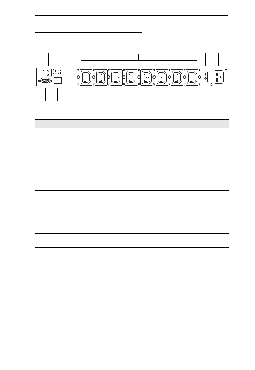
PE6208AV / PE8208AV Rear View
Chapter 1. Introduction
432
7
8
561
No. Item Description
1 Reset
Switch
2 Sensor
LEDs
3 Sensor
Ports
4 Power
Sockets
5 Power
Switch
6 Power
Socket
7 RS-232
Port
Press and release to reboot the PDU. This switch is recessed and
must be pushed with a thin object, such as the end of a paper clip,
or a ballpoint pen.
Two Sensor LEDs light GREEN when a sensor is connected to the
respective sensor port.
External sensors plug into these two RJ-11 ports.
The power cables that connect to the computers plug in here.
This standard rocker switch powers the PE6208AV / PE8208AV
On and Off.
The power cable from the AC source plugs in here.
This port can be used to attach to a computer for local power on/
off/reboot control.
8 LAN Port The Cat 5e cable that connects the PE6208AV / PE8208AV to the
Internet plugs in here.
9

PE6208AV / PE8208AV User Manual
This Page Intentionally Left Blank
10
Chapter 2
1. Important safety information regarding the placement of this device is
provided on page 75. Please review it before proceeding.
2. Make sure that power to all the devices you will be connecting have
been turned off. You must unplug the power cords of any computers
that have the Keyboard Power On function.
1. Vous trouverez des informations de sécurité importantes concernant le
positionnement de l’unité à la page 75. Veuillez les lire attentivement
avant d’aller plus loin.
2. Vérifiez que tous les périphériques à connecter sont éteints. Vous devez
débrancher les câbles d’alimentation des ordinateurs disposant de la
fonction de mise sous tension à partir du clavier.
Hardware Setup
Before You Begin
Stacking and Rack Mounting
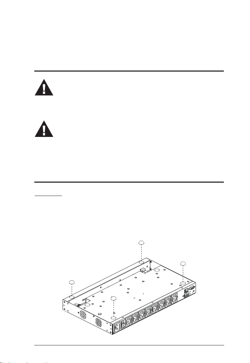
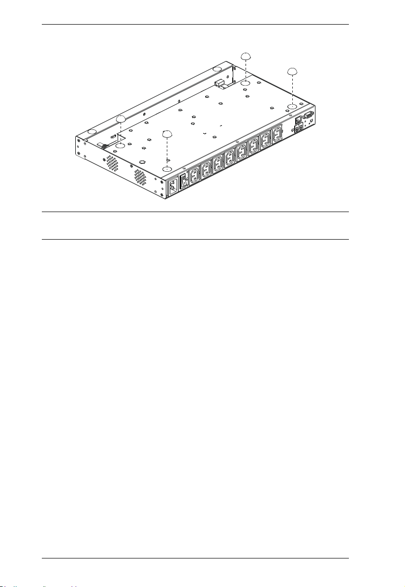
Stacking
The PE6208AV / PE8208AV can be placed on any appropriate level surface
that can safely support its weight plus the weight of its attached cables. To
place or stack the PE6208AV / PE8208AV, remove the backing material from
the bottom of the rubber feet that came with this package, and stick them onto
the switch's bottom panel at the corners, as shown in the diagrams, below:
:
11
PE6208AV / PE8208AV User Manual
Note: To ensure adequate ventilation, allow at least 5.1 cm on each side, and
12.7cm at the back for power cord and cable clearance.
12
Chapter 2. Hardware Setup
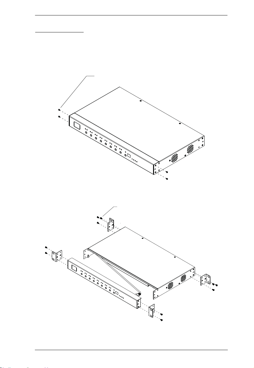
Phillips Flat Head
M3 Screw * 4 pcs
Phillips hex head
M3 Screw * 10 pcs
Rack Mounting
The PE6208AV / PE8208A V can be installed in most standard 19" (1U) racks.
To rack mount the unit do the following:
1. Separate the front and rear modules by removing the four module
attaching screws:
2. Use the screws you just removed, and the ones supplied with the rack
mounting kit to screw the rack mounting brackets into both modules:
13
PE6208AV / PE8208AV User Manual
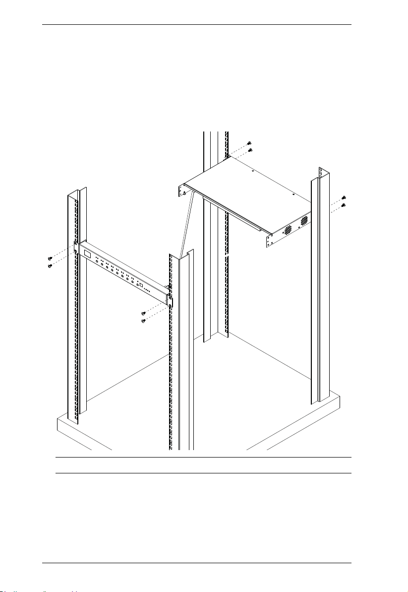
3. There is an RJ-45 port on the front panel and rear module used to connect
the two units. A standard Ethernet cable can be used to extend the front
panel and rear module farther apart.
4. Position the device in the rack and align the holes in the mounting brackets
with the hole in the rack.
5. Screw the mounting brackets to the rack.
Note: Cage nuts are provided for racks that are not prethreaded.
14

Chapter 2. Hardware Setup
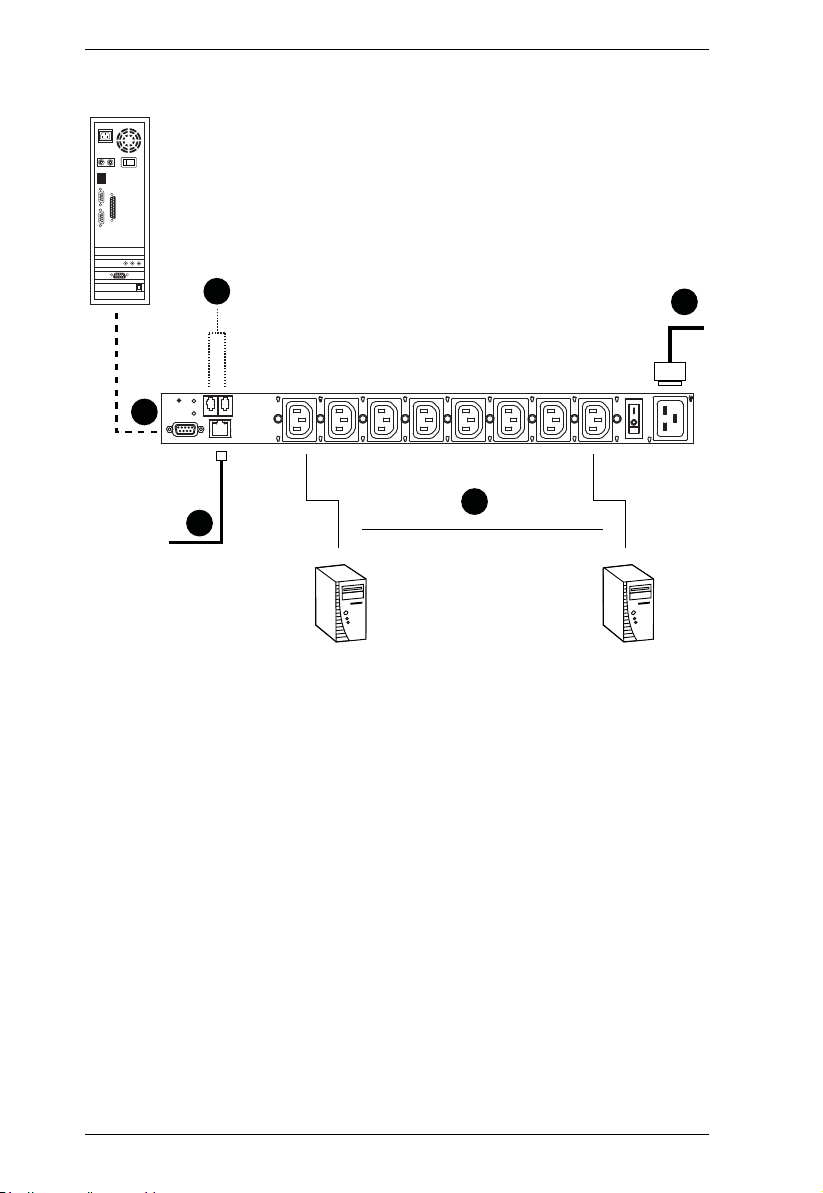
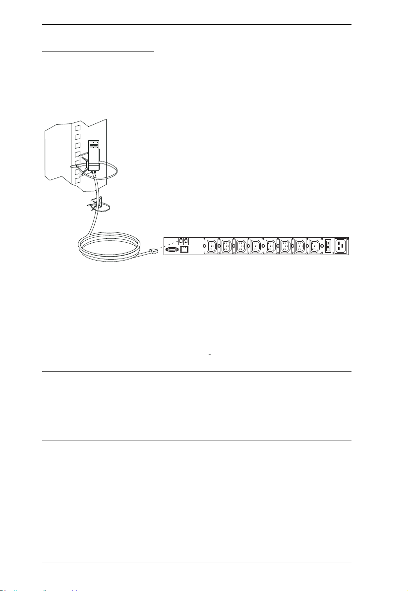
Installation
To install the PDU, refer to the installation diagram below (the numbers in the
diagram correspond to the numbered steps), and do the following:
1. For each device you want to connect, use its power cable to connect from
the device's AC socket to any available outlet on the eco PDU.
2. Plug the Ethernet cable into the eco PDU's LAN port to connect it to the
network.
3. If you are using sensors in your eco PDU installation, connect them to the
sensor ports on the unit’s rear panel.
Note: Sensors are optional. Please see Optional Accessories, page 6, and
the detailed sensor installation diagrams later in this chapter for
further information.
4. If you choose to use a serial device for control, connect its serial port to the
PE6208AV / PE8208AV's RS-232 port.
5. Connect the eco PDU's power cord to an AC power source.
Note: We strongly advise that you do not plug the eco PDU into a multi
socket extension cord, since it may not receive enough amperage to
operate correctly .
6. Once you have finished these installation steps, you can turn on the eco
PDU and the connected devices.
Note: We strongly recommend using cable ties and cable bars to safely and
securely route the cables attached to the front of the unit.
15
PE6208AV / PE8208AV User Manual
3
5
4
1
2
16
Chapter 2. Hardware Setup
Securing the Cables
For added safety, use ATEN Lok-U-Plug cable holders to secure the cables
from your attached devices in place on the eco PDU unit. Secure the cable
holders using the specially designed holes around the individual power outlets,
as shown below:
Note: 1. Cable holders are an optional accessory. See Cable Holders, page 6.
2. Use only the ATEN Lok-U-Plug cable holders that have been
specifically designed to work with the eco PDU. Using any other kind
of cable securing device could be highly dangerous.
17
PE6208AV / PE8208AV User Manual
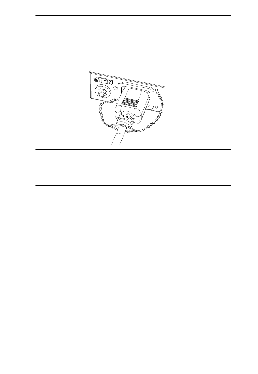
Securing the Sensors
Connect the sensors to the eco PDU’s rear panel sensor ports and secure them
using sensor mounts, tie wraps, and adhesive cable tie holders. If you use a tie
wrap to secure the sensor, tighten the tie wrap over the recessed channel on the
sensor, as shown in the following diagram:
Note: 1. The sensors shown in the above diagram are for reference purposes
only. The sensors for the eco PDU may look slightly different.
2. Depending on the model and type of sensor, sensor mounts, tie wraps,
and adhesive cable tie holders may or may not be provided in the
package.
18

Chapter 3
Basic Operation and
First Time Setup
Operation Methods
NRGence eco PDU models provide three methods to access and manage your
installation: Browser, eco Sensors Energy Management Software and SNMP.
Note: The following sections of this chapter contain information concerning
Browser operation. For eco Sensors operation, please reference the
separate eco Sensors User Manual. The eco Sensors software and User
Manual can be downloaded from the ATEN website.
Browser
The eco PDU can be accessed and controlled via any supported Internet
browser from any platform. See First Time Setup, page 20, and the following
sections in this chapter, for full details.
eco Sensors
The eco Sensors Energy Management Software. eco Sensors provides you with
an easy method for managing multiple devices, offering an intuitive and userfriendly Graphical Interface that allows you to configure a PDU device and
monitor power status of the equipment connected to it. eco Sensors Energy
Management Software can be downloaded from the ATEN website, along with
a separate eco Sensors User Manual.
SNMP
The eco PDU supports any 3rd party V3 SNMP Manager Software. SNMP
Management Information Database (MIB) files for the eco PDU device can be
found on the software CD provided with the eco PDU package.
19
PE6208AV / PE8208AV User Manual
First Time Setup
Once the eco PDU installation has been cabled up, the next task the
Administrator needs to perform involve configuring the network parameters,
changing the default Super Administrator login settings, and adding users.
The way to accomplish this is to log in vi a web browser.
Note: 1. Since this is the first time you are logging in, use the default
Username: administrator; and the default Password: password. For
security purposes we recommend changing them to something unique
(see Changing the Administrator Login, page 22).
2. For remote methods of getting logged in to the PDU, see IP Address
Determination, page 85.
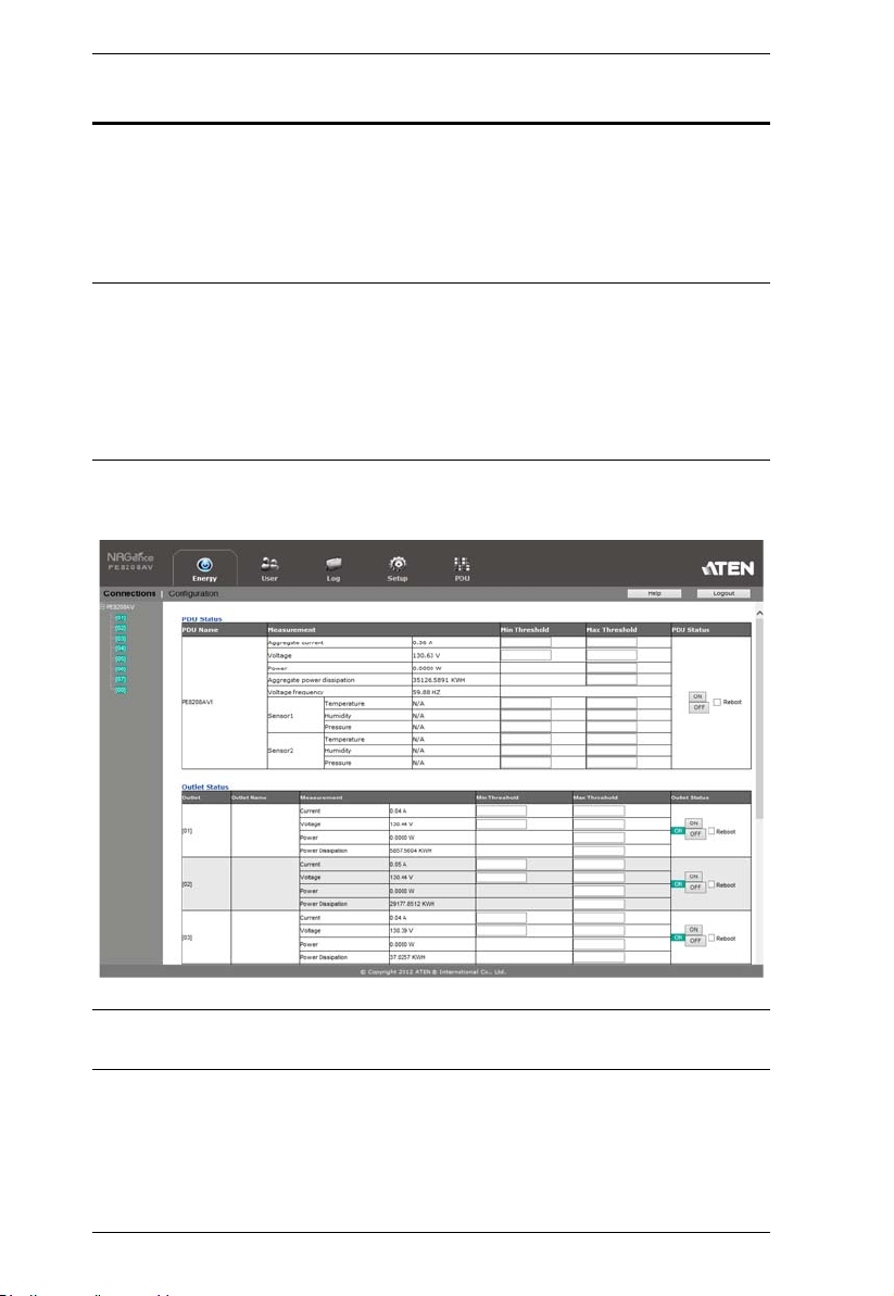
After you successfully log in, the eco PDU Energy/Connections page appears:
Note: Operation details are discussed in Energy, page 26, in the next chapter.
For further setup information, continue with this chapter
20
 Loading...