

Page 1
eco PDU PE Series
PE5108 / PE5208 / PE6108 / PE6208 / PE7108 / PE7208 /
PE8108 / PE8208
Power Distribution Unit
User Manual
www.aten.com
Page 2

eco PDU PE Series User Manual
EMC Information
FEDERAL COMMUNICATIONS COMMISSION INTERFERENCE
STATEMENT: This equipment has been tested and found to comply with the
limits for a Class A digital device, pursuant to Part 15 of the FCC Rules. These
limits are designed to provide reasonable protection against harmful
interference when the equipment is operated in a commercial environment.
This equipment generates, uses, and can radiate radio frequency energy and, if
not installed and used in accordance with the instruction manual, may cause
harmful interference to radio communications. Operation of this equipment in
a residential area is likely to cause harmful interference in which case the user
will be required to correct the interference at his own expense.
The device complies with Part 15 of the FCC Rules. Operation is subject to the
following two conditions: (1) this device may not cause harmful interference,
and (2) this device must accept any interference received, including
interference that may cause undesired operation.
FCC Caution: Any changes or modifications not expressly approved by the
party responsible for compliance could void the user's authority to operate this
equipment.
CE Warning: This is a class A product. In a domestic environment this
product may cause radio interference in which case the user may be required to
take adequate measures.
KCC Statement
유선 제품용 / A 급 기기 ( 업무용 방송 통신 기기 )
이 기기는 업무용 (A 급 ) 전자파적합기기로서 판매자 또는 사용자는 이
점을 주의하시기 바라며 , 가정 외의 지역에서 사용하는 것을 목적으로
합니다 .
RoHS
This product is RoHS compliant.
ii
Page 3
eco PDU PE Series User Manual
VCCI-A
The following contains information that relates to Japan.
SJ/T 11364-2006
The following contains information that relates to China.
iii
Page 4

eco PDU PE Series User Manual
User Information
Online Registration
Be sure to register your product at our online support center:
International http://eservice.aten.com
Telephone Support
For telephone support, call this number:
International 886-2-8692-6959
China 86-10-5255-0110
Japan 81-3-5615-5811
Korea 82-2-467-6789
North America 1-888-999-ATEN ext 4988
United Kingdom 44-8-4481-58923
User Notice
All information, documentation, and specifications contained in this manual are subject
to change without prior notification by the manufacturer. The manufacturer makes no
representations or warranties, either expressed or implied, with respect to the contents
hereof and specifically disclaims any warranties as to merchantability or fitness for any
particular purpose. Any of the manufacturer's software describe d in this manual is sold
or licensed as is. Should the programs prove defective following their purchase, the
buyer (and not the manufacturer, its distributor, or its dealer), assumes the entire cost of
all necessary servicing, repair and any incidental or consequential damages resulting
from any defect in the software.
The manufacturer of this system is not responsible for any radio and/or TV interference
caused by unauthorized modifications to this device. It is the responsibility of the user
to correct such interference.
The manufacturer is not responsible for any damage incurred in the operation of this
system if the correct operational voltage setting was not selected prior to operation.
PLEASE VERIFY THAT THE VOLTAGE SETTING IS CORRECT BEFORE USE.
If any bodily injury or property damage with respect to operation of the product results
from users not having installed the product in accordance with the instructions provided
in the product’s user manual, or the product is used in an environment with a current
load over the designed specifications of the product, ATEN is not liable for any loss or
damage.
iv
Page 5

eco PDU PE Series User Manual
Set the maximum permissible breaker protection in the building circuitry to the
current rating specified on the rating plate. Observe all national regulations and
safety codes as well as deviations for breakers.
Only connect the PE Device to a grounded power outlet or a grounded system!
Make sure that the total current input of the connected systems does not exceed
the current rating specified on the rating plate of the PE Device.
There is a risk of explosion if the battery is replaced with an incorrect type.
Dispose of used batteries according to the relevant instructions.
PE Device Safety Notice
Consignes de sècuritè relatives à l’unitè PE
Installez sur le circuit du bâtiment des disjoncteurs permettant d’assurer la
protection maximale autorisée, en respectant le courant nominal spécifié sur la
plaque signalétique. Veuillez respecter l’ensemble des réglementations nationales
en vigueur et des codes de sécurité ainsi que les déviations recommandèes pour les
disjoncteurs.
Ne connectez l’unité PE qu’à une prise de courant avec borne de terre ou à un
système mis à la terre!
Assurez-vous que le courant d’entrée total des systèmes connectés ne dépasse pas
le courant nominal spécifié sur la plaque signalétique de l’unité PE.
Il existe un risque d’explosion si la batterie est remplacée par une batterie de type
incorrect. Jetez les batteries usagées en respectant les instructions adequates.
v
Page 6

eco PDU PE Series User Manual
Copyright © 2015 ATEN® International Co., Ltd.
Manual Part No. PAPE-0345-AX1G
Printing Date: 2015-12-09
NRGence and the NRGence logo are registered trademarks of ATEN International Co., Ltd. All rights reserved.
All other brand names and trademarks are the registered property of their respective owners.
Package Contents
The eco PDU PE Series package consists of:
1 PE5108 / PE5208 / PE6108 / PE6208 / PE7108 / PE7208 / PE8108 /
PE8208 Power Distribution Unit
1 Power Cord
1 Mounting Kit
1 Software CD
1 User Instructions*
Check to make sure that all of the components are present and in good order.
If anything is missing, or was damaged in shipping, contact your dealer.
Read this manual thoroughly and follow the installation and operation
procedures carefully to prevent any damage to the switch or to any other
devices on the eco PDU installation.
* Features may have been added to the eco PDU since this manual was
published. Please visit our website to download the most up-to-date version.
vi
Page 7

eco PDU PE Series User Manual
Contents
EMC Information. . . . . . . . . . . . . . . . . . . . . . . . . . . . . . . . . . . . . . . . . . . . .ii
RoHS. . . . . . . . . . . . . . . . . . . . . . . . . . . . . . . . . . . . . . . . . . . . . . . . . . . . . . ii
VCCI-A . . . . . . . . . . . . . . . . . . . . . . . . . . . . . . . . . . . . . . . . . . . . . . . . . . . .iii
SJ/T 11364-2006. . . . . . . . . . . . . . . . . . . . . . . . . . . . . . . . . . . . . . . . . . . . .iii
User Information . . . . . . . . . . . . . . . . . . . . . . . . . . . . . . . . . . . . . . . . . . . . iv
Online Registration . . . . . . . . . . . . . . . . . . . . . . . . . . . . . . . . . . . . . . . iv
Telephone Support . . . . . . . . . . . . . . . . . . . . . . . . . . . . . . . . . . . . . . . iv
User Notice . . . . . . . . . . . . . . . . . . . . . . . . . . . . . . . . . . . . . . . . . . . . . iv
PE Device Safety Notice. . . . . . . . . . . . . . . . . . . . . . . . . . . . . . . . . . . .v
Consignes de sècuritè relatives à l’unitè PE . . . . . . . . . . . . . . . . . . . . .v
Package Contents. . . . . . . . . . . . . . . . . . . . . . . . . . . . . . . . . . . . . . . . . . . vi
About This Manual . . . . . . . . . . . . . . . . . . . . . . . . . . . . . . . . . . . . . . . . . . .x
Conventions . . . . . . . . . . . . . . . . . . . . . . . . . . . . . . . . . . . . . . . . . . . . xi
Product Information. . . . . . . . . . . . . . . . . . . . . . . . . . . . . . . . . . . . . . . . . . xi
Chapter 1.
Introduction
Overview. . . . . . . . . . . . . . . . . . . . . . . . . . . . . . . . . . . . . . . . . . . . . . . . . . .1
PE Series eco PDU Comparison Chart. . . . . . . . . . . . . . . . . . . . . . . . .3
Features . . . . . . . . . . . . . . . . . . . . . . . . . . . . . . . . . . . . . . . . . . . . . . . . . . .4
Power Distribution. . . . . . . . . . . . . . . . . . . . . . . . . . . . . . . . . . . . . . . . .4
Remote Access. . . . . . . . . . . . . . . . . . . . . . . . . . . . . . . . . . . . . . . . . . .4
Operation. . . . . . . . . . . . . . . . . . . . . . . . . . . . . . . . . . . . . . . . . . . . . . . .4
Management . . . . . . . . . . . . . . . . . . . . . . . . . . . . . . . . . . . . . . . . . . . . .5
Security . . . . . . . . . . . . . . . . . . . . . . . . . . . . . . . . . . . . . . . . . . . . . . . . .5
Requirements . . . . . . . . . . . . . . . . . . . . . . . . . . . . . . . . . . . . . . . . . . . . . . .6
Optional Accessories . . . . . . . . . . . . . . . . . . . . . . . . . . . . . . . . . . . . . . . . .7
Sensors. . . . . . . . . . . . . . . . . . . . . . . . . . . . . . . . . . . . . . . . . . . . . . . . .7
Cable Holders . . . . . . . . . . . . . . . . . . . . . . . . . . . . . . . . . . . . . . . . . . . .7
Components . . . . . . . . . . . . . . . . . . . . . . . . . . . . . . . . . . . . . . . . . . . . . . . .8
PE5108A / PE7108A Front View. . . . . . . . . . . . . . . . . . . . . . . . . . . . . .8
PE5208A / PE7208A Front View. . . . . . . . . . . . . . . . . . . . . . . . . . . . . .8
PE5108A / PE5208A / PE7108A / PE7208A Rear View. . . . . . . . . . . .8
PE5108A / PE5208A / PE7108A / PE7208A Readout Section. . . . . . .9
PE5108B / PE5108G / PE7108B / PE7108G Front View . . . . . . . . . .10
PE5208B / PE5208G / PE7208B / PE7208G Front View . . . . . . . . . .10
PE5108B / PE5108G / PE5208B / PE5208G / PE7108B / PE7108G /
PE7208B / PE7208G Rear View. . . . . . . . . . . . . . . . . . . . . . . . . . . . .10
PE5108B / PE5108G / PE5208B / PE5208G / PE7108B / PE7108G /
PE7208B / PE7208G Readout Section. . . . . . . . . . . . . . . . . . . . . . . .11
PE6108A / PE8108A Front View. . . . . . . . . . . . . . . . . . . . . . . . . . . . .12
PE6208A / PE8208A Front View. . . . . . . . . . . . . . . . . . . . . . . . . . . . .12
PE6108A / PE6208A / PE8108A / PE8208A Rear View. . . . . . . . . . .12
PE6108A / PE6208A / PE8108A / PE8208A Readout Section. . . . . .13
vii
Page 8

eco PDU PE Series User Manual
PE6108B / PE6108G / PE8108B / PE8108G Front View . . . . . . . . . . 14
PE6208B / PE6208G / PE8208B / PE8208G Front View . . . . . . . . . . 14
PE6108B / PE6108G / PE6208B / PE6208G / PE8108B / PE8108G /
PE8208B / PE8208G Rear View. . . . . . . . . . . . . . . . . . . . . . . . . . . . . 14
PE6108B / PE6108G / PE6208B / PE6208G / PE8108B / PE8108G /
PE8208B / PE8208G Readout Section. . . . . . . . . . . . . . . . . . . . . . . .15
Chapter 2.
Hardware Setup
Before You Begin . . . . . . . . . . . . . . . . . . . . . . . . . . . . . . . . . . . . . . . . . . . 17
Rack Mounting . . . . . . . . . . . . . . . . . . . . . . . . . . . . . . . . . . . . . . . . . . . . .17
Installation. . . . . . . . . . . . . . . . . . . . . . . . . . . . . . . . . . . . . . . . . . . . . . . . .18
Securing the Cables . . . . . . . . . . . . . . . . . . . . . . . . . . . . . . . . . . . . . .19
Securing the Sensors . . . . . . . . . . . . . . . . . . . . . . . . . . . . . . . . . . . . .20
Chapter 3.
Basic Operation and
First Time Setup
Operation Methods. . . . . . . . . . . . . . . . . . . . . . . . . . . . . . . . . . . . . . . . . .21
Browser. . . . . . . . . . . . . . . . . . . . . . . . . . . . . . . . . . . . . . . . . . . . . . . .21
eco Sensors . . . . . . . . . . . . . . . . . . . . . . . . . . . . . . . . . . . . . . . . . . . .21
SNMP . . . . . . . . . . . . . . . . . . . . . . . . . . . . . . . . . . . . . . . . . . . . . . . . . 21
First Time Setup . . . . . . . . . . . . . . . . . . . . . . . . . . . . . . . . . . . . . . . . . . . .22
Network Configuration. . . . . . . . . . . . . . . . . . . . . . . . . . . . . . . . . . . . .23
Changing the Administrator Login. . . . . . . . . . . . . . . . . . . . . . . . . . . .24
Moving On . . . . . . . . . . . . . . . . . . . . . . . . . . . . . . . . . . . . . . . . . . . . . . . . 24
Chapter 4.
Browser Operation
Logging In. . . . . . . . . . . . . . . . . . . . . . . . . . . . . . . . . . . . . . . . . . . . . . . . .25
The eco PDU Main Page . . . . . . . . . . . . . . . . . . . . . . . . . . . . . . . . . . . . .26
Page Components . . . . . . . . . . . . . . . . . . . . . . . . . . . . . . . . . . . . . . . 27
Energy . . . . . . . . . . . . . . . . . . . . . . . . . . . . . . . . . . . . . . . . . . . . . . . . . . .28
Connections . . . . . . . . . . . . . . . . . . . . . . . . . . . . . . . . . . . . . . . . . . . .28
Configuration. . . . . . . . . . . . . . . . . . . . . . . . . . . . . . . . . . . . . . . . . . . .31
User . . . . . . . . . . . . . . . . . . . . . . . . . . . . . . . . . . . . . . . . . . . . . . . . . . . . . 34
Administrator Information . . . . . . . . . . . . . . . . . . . . . . . . . . . . . . . . . .34
User Information . . . . . . . . . . . . . . . . . . . . . . . . . . . . . . . . . . . . . . . . .35
Log . . . . . . . . . . . . . . . . . . . . . . . . . . . . . . . . . . . . . . . . . . . . . . . . . . . . . .36
The System Log Event List. . . . . . . . . . . . . . . . . . . . . . . . . . . . . . . . . 36
Notification Settings . . . . . . . . . . . . . . . . . . . . . . . . . . . . . . . . . . . . . .37
Setup . . . . . . . . . . . . . . . . . . . . . . . . . . . . . . . . . . . . . . . . . . . . . . . . . . . .38
Device Configuration. . . . . . . . . . . . . . . . . . . . . . . . . . . . . . . . . . . . . .38
Date/Time . . . . . . . . . . . . . . . . . . . . . . . . . . . . . . . . . . . . . . . . . . . . . .45
Security. . . . . . . . . . . . . . . . . . . . . . . . . . . . . . . . . . . . . . . . . . . . . . . .47
Login Failures . . . . . . . . . . . . . . . . . . . . . . . . . . . . . . . . . . . . . . . . . . .47
Working Mode. . . . . . . . . . . . . . . . . . . . . . . . . . . . . . . . . . . . . . . . . . . 47
viii
Page 9

eco PDU PE Series User Manual
Account Policy. . . . . . . . . . . . . . . . . . . . . . . . . . . . . . . . . . . . . . . . . . .48
Login String / IP Filter / Mac Filter. . . . . . . . . . . . . . . . . . . . . . . . . . . .49
Authentication & Authorization . . . . . . . . . . . . . . . . . . . . . . . . . . . . . .52
Private Certificate . . . . . . . . . . . . . . . . . . . . . . . . . . . . . . . . . . . . . . . .53
PDU. . . . . . . . . . . . . . . . . . . . . . . . . . . . . . . . . . . . . . . . . . . . . . . . . . . . . .55
Firmware File. . . . . . . . . . . . . . . . . . . . . . . . . . . . . . . . . . . . . . . . . . . .55
Backup/Restore. . . . . . . . . . . . . . . . . . . . . . . . . . . . . . . . . . . . . . . . . .57
Safety Instructions. . . . . . . . . . . . . . . . . . . . . . . . . . . . . . . . . . . . . . . . . . .59
General . . . . . . . . . . . . . . . . . . . . . . . . . . . . . . . . . . . . . . . . . . . . . . . .59
Consignes de sécurité. . . . . . . . . . . . . . . . . . . . . . . . . . . . . . . . . . . . . . . .61
Général . . . . . . . . . . . . . . . . . . . . . . . . . . . . . . . . . . . . . . . . . . . . . . . .61
Rack Mounting . . . . . . . . . . . . . . . . . . . . . . . . . . . . . . . . . . . . . . . . . .64
The eco PDU’s Main Power Cord . . . . . . . . . . . . . . . . . . . . . . . . . . . .64
Securing the Power Cables. . . . . . . . . . . . . . . . . . . . . . . . . . . . . . . . .64
Montage sur bâti . . . . . . . . . . . . . . . . . . . . . . . . . . . . . . . . . . . . . . . . .65
Le cordon d’alimentation principale de l’unité d’alimentation éco . . . .65
Fixation des câbles d’alimentation . . . . . . . . . . . . . . . . . . . . . . . . . . .65
Appendix
Technical Support. . . . . . . . . . . . . . . . . . . . . . . . . . . . . . . . . . . . . . . . . . .67
International. . . . . . . . . . . . . . . . . . . . . . . . . . . . . . . . . . . . . . . . . . . . .67
North America . . . . . . . . . . . . . . . . . . . . . . . . . . . . . . . . . . . . . . . . . . .67
IP Address Determination. . . . . . . . . . . . . . . . . . . . . . . . . . . . . . . . . . . . .68
Specifications . . . . . . . . . . . . . . . . . . . . . . . . . . . . . . . . . . . . . . . . . . . . . .70
PE5108A / PE5208A / PE7108A / PE7208A. . . . . . . . . . . . . . . . . . . .70
PE5108B / PE5208B / PE7108B / PE7208B. . . . . . . . . . . . . . . . . . . .71
PE5108G / PE5208G / PE7108G / PE7208G. . . . . . . . . . . . . . . . . . .72
PE6108A / PE6208A / PE8108A / PE8208A. . . . . . . . . . . . . . . . . . . .73
PE6108B / PE6208B / PE8108B / PE8208B. . . . . . . . . . . . . . . . . . . .74
PE6108G / PE6208G / PE8108G / PE8208G. . . . . . . . . . . . . . . . . . .75
Administrator Login Failure. . . . . . . . . . . . . . . . . . . . . . . . . . . . . . . . . . . .76
Limited Warranty. . . . . . . . . . . . . . . . . . . . . . . . . . . . . . . . . . . . . . . . . . . .77
ix
Page 10

eco PDU PE Series User Manual
About This Manual
This User Manual is provided to help you get the most from your eco PDU
system. It covers all aspects of installation, configuration and operation. An
overview of the information found in the manual is provided below.
Chapter 1, Introduction, introduces you to the eco PDU system. Its purpose,
features and benefits are presented, and its front and back panel components
are described.
Chapter 2, Hardware Setup, provides step-by-step instructions for setting
up your installation.
Chapter 3, Basic Operation and First Time Setup, explains the
procedures that the Administrator employs to set up the eco PDU network
environment, and change the default username and password.
Chapter 4, Browser Operation, describes how to log in to the eco PDU with
an internet browser, and explains the layout and components of the eco PDU’s
user interface.
An Appendix, provides specifications and other technical information
regarding the eco PDU.
x
Page 11

eco PDU PE Series User Manual
Conventions
This manual uses the following conventions:
Monospaced Indicates text that you should key in.
[ ] Indicates keys you should press. For example, [Enter] means
to press the Enter key. If keys need to be chorded, they
appear together in the same bracket with a plus sign
between them: [Ctrl+Alt].
1. Numbered lists represent procedures with sequential steps.
♦ Bullet lists provide information, but do not involve sequential
steps.
→ Indicates selecting the option (on a menu or dialog box, for
example), that comes next. For example, Start
means to open the Start menu, and then select Run.
Indicates critical information.
→ Run
Product Information
For information about all NRGence products and how they can help you
connect without limits, visit NRGence on the Web or contact an NRGence
Authorized Reseller. Visit NRGence on the Web for a list of locations and
telephone numbers
International – http://www.aten.com
North America – http://www.aten-usa.com
xi
Page 12

eco PDU PE Series User Manual
This Page Intentionally Left Blank
xii
Page 13

Chapter 1
Introduction
Overview
ATEN has developed a new generation of green energy power distribution
units (PDUs) to effectively increase the efficiency of data center power usage
The NRGence PE5108 / PE5208/ PE6108 / PE6208 / PE7108 / PE7208 /
PE8108 and PE8208 eco PDUs are intelligent PDUs that contain 8 AC outlets
and are available in various IEC or NEMA socket configurations.
They provide secure, centralized, intelligent, power management (power on,
off, cycle) of data center IT equipment (servers, storage systems, KVM
switches, network devices, serial data devices, etc.), as well as the ability to
monitor the center's health environment via sensors*. The basic characteristics
of each model are shown in the table on page 3.
NRGence eco PDUs offer remote power control combined with real-time
power measurement - allowing you to control and monitor the power status of
devices attached to the PDUs, either at the PDU device or outlet level, from
practically any location via a TCP/IP connection.
The power status of each outlet can be set individually, allowing users to switch
each device On/Off. The eco PDU also offers comprehensive power analysis
reports which can separate departments and locations, providing precise
measurements of current, voltage, power and watt-hour in a real-time display.
Installation and operation is fast and easy: plugging cables into their
appropriate ports and user-friendly browser-based configuration and
management is all that is entailed. Since the eco PDU firmware is upgradeable
over the Net, you can stay current with the latest functionality improvements
simply by downloading updates from our website as they become available.
NRGence eco PDU supports any 3rd party v3 SNMP Manager Software and
NRGence eco Sensors (eco PDU Manager Software). NRGence eco Sensors
provides you with an easy method for managing multiple devices, offering an
intuitive and user-friendly Graphical User Interface that allows you to
configure a PDU device and monitor power status of the equipment connected
to it.
(Continues on next page.)
1
Page 14

eco PDU PE Series User Manual
(Continued from previous page.)
This series of ATEN eco PDUs have a circuit breaker alert that can sound an
alarm and send SNMP trap or e-mail alerts when a trip occurs. This feature
provides a faster response time to recover servers and other devices when a
circuit overload causes a loss of power.
With its advanced security features and ease of operation, the eco PDU is the
most convenient, most reliable, and most cost effective way to remotely
manage power access for multiple computer installations and allocate power
resources in the most efficient way possible.
Note: Sensors are optional accessories. A sensor-enabled installation is
required to generate a more complete energy-efficient data and chart.
Higher sensor installation density is helpful to generate more accurate
data. See Optional Accessories, page 7, for further information.
2
Page 15

PE Series eco PDU Comparison Chart
Chapter 1. Introduction
Model
PE5108A NEMA 5-15P NEMA 5-15R PDU 12A 12A
PE5108B NEMA 6-15P IEC C13 PDU 12A 12A
PE5108G IEC C14 IEC C13 PDU 10A 10A
PE5208A NEMA 5-20P NEMA 5-20R PDU 16A 16A
PE5208B NEMA 6-20P IEC C13 / C19 PDU 12A / 16A 12A
PE5208G IEC C20 IEC C13 / C19 PDU 10A / 16A 16A
PE6108A NEMA 5-15P NEMA 5-15R PDU 12A 12A
PE6108B NEMA 6-15P IEC C13 PDU 12A 12A
PE6108G IEC C14 IEC C13 PDU 10A 10A
PE6208A NEMA 5-20P NEMA 5-20R PDU 16A 16A
PE6208B NEMA 6-20P IEC C13 / C19 PDU 12A / 16A 16A
PE6208G IEC C20 IEC C13 / C19 PDU 10A / 16A 16A
PE7108A NEMA 5-15P NEMA 5-15R Outlet 12A 12A
PE7108B NEMA 6-15P IEC C13 Outlet 12A 12A
PE7108G IEC C14 IEC C13 Outlet 10A 10A
PE7208A NEMA 5-20P NEMA 5-20R Outlet 16A 16A
PE7208B NEMA 6-20P IEC C13 / C19 Outlet 12A / 16A 16A
PE7208G IEC C20 IEC C13 / C19 Outlet 10A / 16A 16A
PE8108A NEMA 5-15P NEMA 5-15R Outlet 12A 12A
PE8108B NEMA 6-15P IEC C13 Outlet 12A 12A
PE8108G IEC C14 IEC C13 Outlet 10A 10A
PE8208A NEMA 5-20P NEMA 5-20R Outlet 16A 16A
PE8208B NEMA 6-20P IEC C13 / C19 Outlet 12A / 16A 16A
PE8208G IEC C20 IEC C13 / C19 Outlet 10A / 16A 16A
Power Cord
(IEC C19 to)
Outlets
Monitoring
Level
Amps
Per Port Total
Note: For the complete specifications of individual m odels, please reference
Specifications, page 70.
3
Page 16

eco PDU PE Series User Manual
Features
Power Distribution
Space saving 1U rack mount design with rear mounting
IEC or NEMA outlet models
3 digit 7-segment front panel LED shows Current / IP Address for PDU /
Outlet
Remote users can monitor outlet status via web pages on their browsers
Safe shutdown support
Separate power for the unit's own power and its power outlets. The user
interface is still accessible even when an overload condition trips the
devices' circuit breaker
Remote Access
Remote power control via TCP/IP and a built in 10/100 Ethernet port
Network Interfaces: TCP/IP, UDP, HTTP, HTTPS, SSL, SMTP, DHCP,
NTP, DNS, 10Base-T/100Base-TX, auto sense, Ping
eco PDU Power Management software – eco Sensors
Supports SNMP Manager V3
Operation
Remote power outlet control (On, Off, Power Cycle) by individual outlets
Power-on sequencing – users can set the power on sequence and delay
time for each port to allow equipment to be turned on in the proper order
Easy setup and operation via a browser-based user interface
Multibrowser support (IE, Mozilla, Firefox, Chrome, Safari, Opera,
Netscape)
RTC support to keep the timer running during times of no power.
Up to 8 user accounts and 1 administrator account.
4
Page 17

Chapter 1. Introduction
Management
Power status measurement at the PDU/Outlet level
LED indicators for current and IP address at the PDU device and/or Outlet
levels.
Real-time current, voltage, and kWH displayed in a browsed-based UI for
monitoring at the PDU level (PE5108 / PE5208 / PE6108 / PE6208) and at
the outlet level (PE7108 / PE7208 / PE8108 / PE8208)
Circuit breaker alert sounds an alarm and sends SNMP trap or e-mail alerts
when a circuit breaker trips
Current and voltage threshold setting
Naming support for outlets
User outlet access assignment on an outlet-by-outlet basis.
Event logging and syslog support
Upgradeable firmware
Multilanguage support: English, Traditional Chinese, Simplified Chinese,
Japanese, German, Italian, Spanish, French.
Security
Two-level password security
Strong security features include strong password protection and advanced
encryption technologies – 128 bit SSL
Remote authentication support: RADIUS
5
Page 18

eco PDU PE Series User Manual
Requirements
Browsers accessing the eco PDU unit must support SSL 128 bit
encryption.
For cold booting of attached computers, the computer's BIOS must
support Wake on LAN or System after AC Back.
For Safe Shutdown:
The computer must be running Windows (Windows 2000 or higher) or
Linux.
The Safe Shutdown program (available by download from our website
or on the software CD included), must be installed and running on the
computer.
6
Page 19

Chapter 1. Introduction
Optional Accessories
Sensors
Sensors are optional accessories. You can use the eco PDU unit without
sensors. However, if you want to have complete energy management of an
instrumented data center with the use of the eco PDU, you would need to use
eco Sensors software and install 4 sensors for each of the racks to generate a
complete energy-efficient data and chart. Higher sensor installation density is
helpful to generate more accurate data. 8-port models have 2 sensor ports. In
this case, Sensor 1 needs to be installed at the intake of the rack and sensor 2
needs to be placed at the exhaust of IT equipment of the rack. A sensor-enabled
installation is required to generate a more complete energy-efficient data and
chart. Higher sensor installation density is helpful to generate more accurate
data. Available sensors are show in the table, below:
Sensor Part Number
Temperature EA1140
Temperature / Humidity EA1240
Differential Pressure / Temperature EA1340
Sensor Management
Sensors can be managed via the eco PDU’s built-in graphical user interface
(GUI) or with the NRGence eco Sensors software that can be downloaded from
the ATEN website. The download link can be found on the software CD
provided with the eco PDU package.
Cable Holders
Cable holders are optional accessories. For added safety, use ATEN Lok-UPlug cable holders to secure the cables from your attached devices in place on
the eco PDU unit. Use only the ATEN Lok-U-Plug cable holders that have
been specifically designed to work with the eco PDU. Using any other kind of
cable securing device could be highly dangerous.
Part Number Description
2X-EA07 Lok-U-Plug Cable Holder (10 pcs)
2X-EA08 Lok-U-Plug Installation Tool (4 pcs)
7
Page 20
eco PDU PE Series User Manual
1
234 5
6
9
8
7
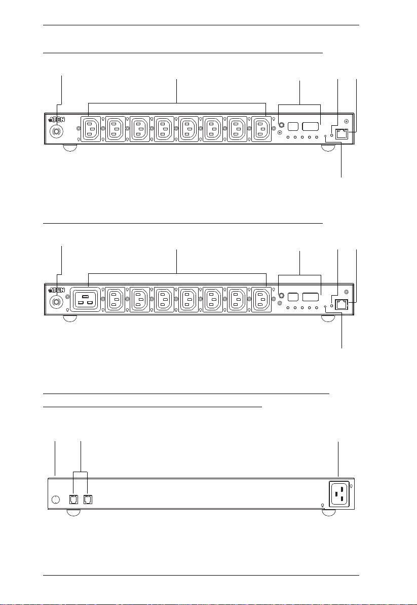
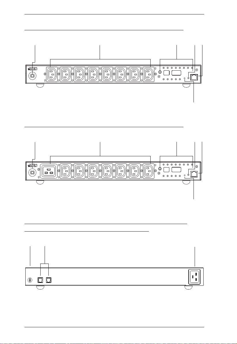
Components
PE5108A / PE7108A Front View
1
234 5
PE5208A / PE7208A Front View
6
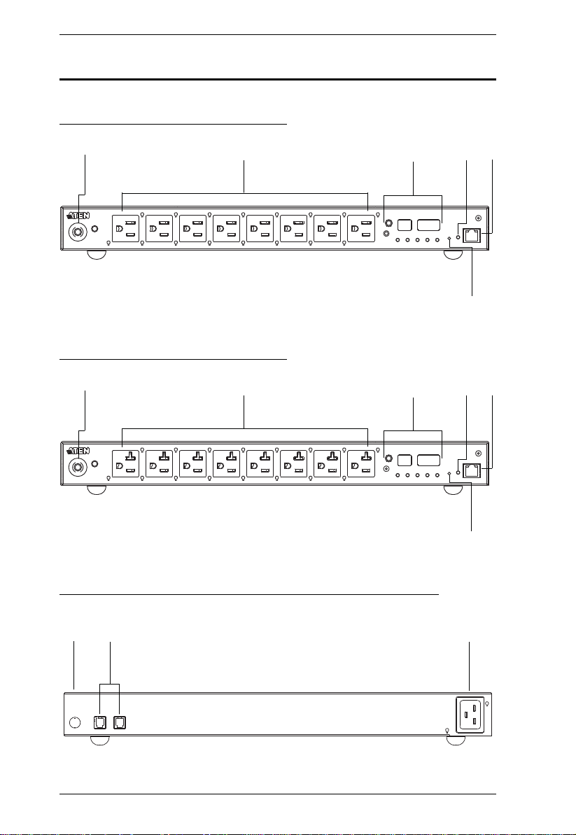
PE5108A / PE5208A / PE7108A / PE7208A Rear View
8
Page 21
Chapter 1. Introduction
3
SELECT
PDU
CURRENT
OUTLET
CURRENT
IP
ADDRESS
SENSOR
1
SENSOR
2
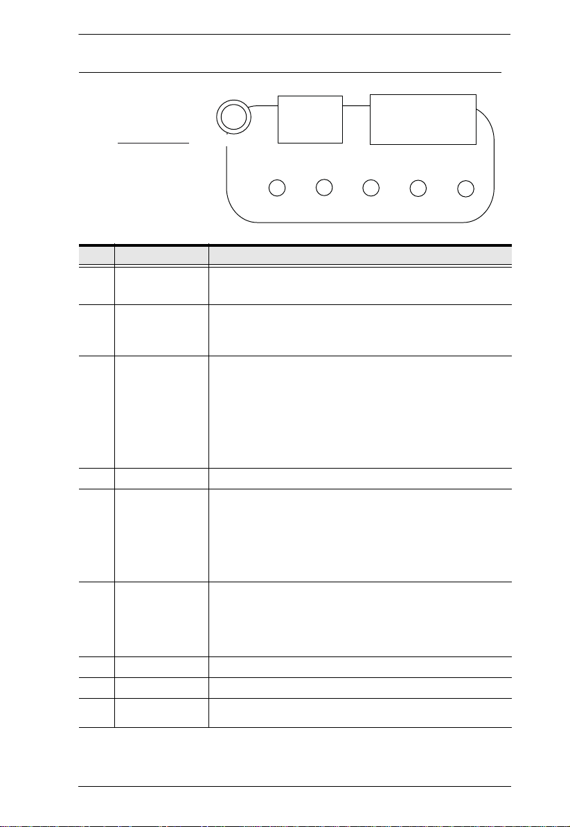
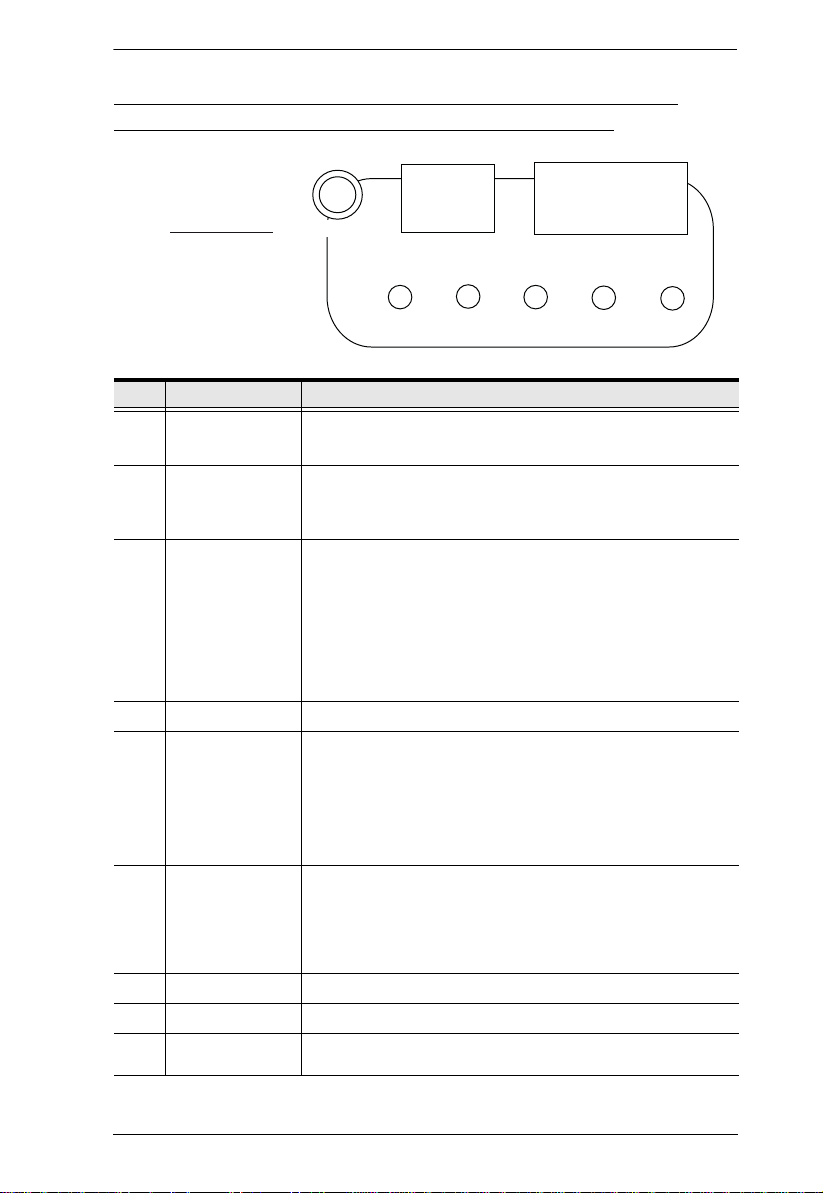
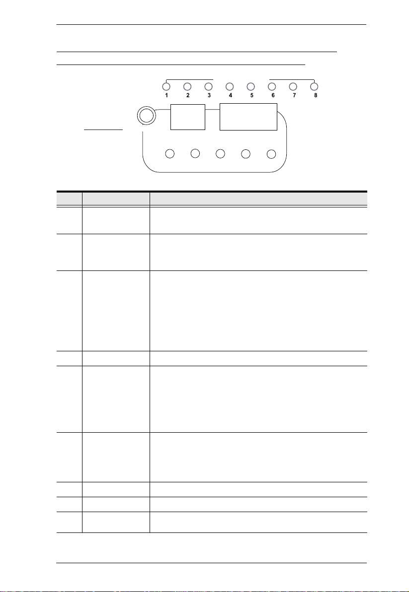
PE5108A / PE5208A / PE7108A / PE7208A Readout Section
No. Item Description
1 Circuit Breaker
Pushbutton
2 Power Sockets
3 Readout Section
4 Power LED
5 LAN Port and
LEDs
6 Reset Switch
Grounding Terminal The wire used to ground the unit connects here.
7
8 Sensor Ports
9 Power Socket
As a safety measure, if there is an overcurrent situation regarding the
device’s power, the circuit breakers will trip. Press the button to
recover normal operation.
8 x NEMA 5-15R or 8 x NEMA 5-20R
Note: Holes for ATEN Lok-U-Plug cable holders are located around
the sockets. See Securing the Cables, page 19, for further
information.
The selection (PDU Current / Outlet Current / IP Address) appears
in the first (1-digit) display window.
PDU Current / Outlet Current / IP Address appear in the second
(3-digit) display window
The LEDs above the items indicate which one the readout relates
to.
Press the button next to the first display window to cycle the
selection among the items.
The LED lights when the eco PDU is ready to operate.
The cable that connects the eco PDU to the LAN plugs in here. The
Link and LAN LEDs are built into the LAN port:
Link: Lights GREEN to indicate that a connection via the eco PDU's
RJ-45 Ethernet port has been established. Flashes to indicate data is
being transmitted.
LAN: Lights ORANGE to indicate 10 Mbps data transmission speed.
The LED lights GREEN to indicate 100 Mbps data transmission
speed.
This switch is recessed and must be pushed with a thin object, such
as the end of a paper clip.
Press and release to reboot the device.
Press and hold for more that three seconds to reset the eco
PDU to its factory default settings
External sensors plug into these two RJ-11 ports.
The power cord that connects the unit to an AC power source plugs
in here.
9
Page 22
eco PDU PE Series User Manual
9
8
7
PE5108B / PE5108G / PE7108B / PE7108G Front View
1
23
PE5208B / PE5208G / PE7208B / PE7208G Front View
1
23
4 5
6
4 5
6
PE5108B / PE5108G / PE5208B / PE5208G / PE7108B / PE7108G / PE7208B / PE7208G Rear View
10
Page 23
3
SELECT
PDU
CURRENT
OUTLET
CURRENT
IP
ADDRESS
SENSOR
1
SENSOR
2
Chapter 1. Introduction
PE5108B / PE5108G / PE5208B / PE5208G / PE7108B / PE7108G / PE7208B / PE7208G Readout Section
No. Item Description
1 Circuit Breaker
Pushbutton
2 Power Sockets
3 Readout Section
4 Power LED
5 LAN Port and
LEDs
6 Reset Switch
Grounding Terminal The wire used to ground the unit connects here.
7
8 Sensor Ports
9 Power Socket
As a safety measure, if there is an overcurrent situation regarding the
device’s power, the circuit breakers will trip. Press the button to
recover normal operation.
8 x IEC320 C13 or 7 x IEC320 C13 + 1 x C19
Note: Holes for ATEN Lok-U-Plug cable holders are located around
the sockets. See Securing the Cables, page 19, for further
information.
The selection (PDU Current / Outlet Current / IP Address) appears
in the first (1-digit) display window.
PDU Current / Outlet Current / IP Address appear in the second
(3-digit) display window
The LEDs above the items indicate which one the readout relates
to.
Press the button next to the first display window to cycle the
selection among the items.
The LED lights when the eco PDU is ready to operate.
The cable that connects the eco PDU to the LAN plugs in here. The
Link and LAN LEDs are built into the LAN port:
Link: Lights GREEN to indicate that a connection via the eco PDU's
RJ-45 Ethernet port has been established. Flashes to indicate data is
being transmitted.
LAN: Lights ORANGE to indicate 10 Mbps data transmission speed.
The LED lights GREEN to indicate 100 Mbps data transmission
speed.
This switch is recessed and must be pushed with a thin object, such
as the end of a paper clip.
Press and release to reboot the device.
Press and hold for more that three seconds to reset the eco
PDU to its factory default settings
External sensors plug into these two RJ-11 ports.
The power cord that connects the unit to an AC power source plugs
in here.
11
Page 24
eco PDU PE Series User Manual
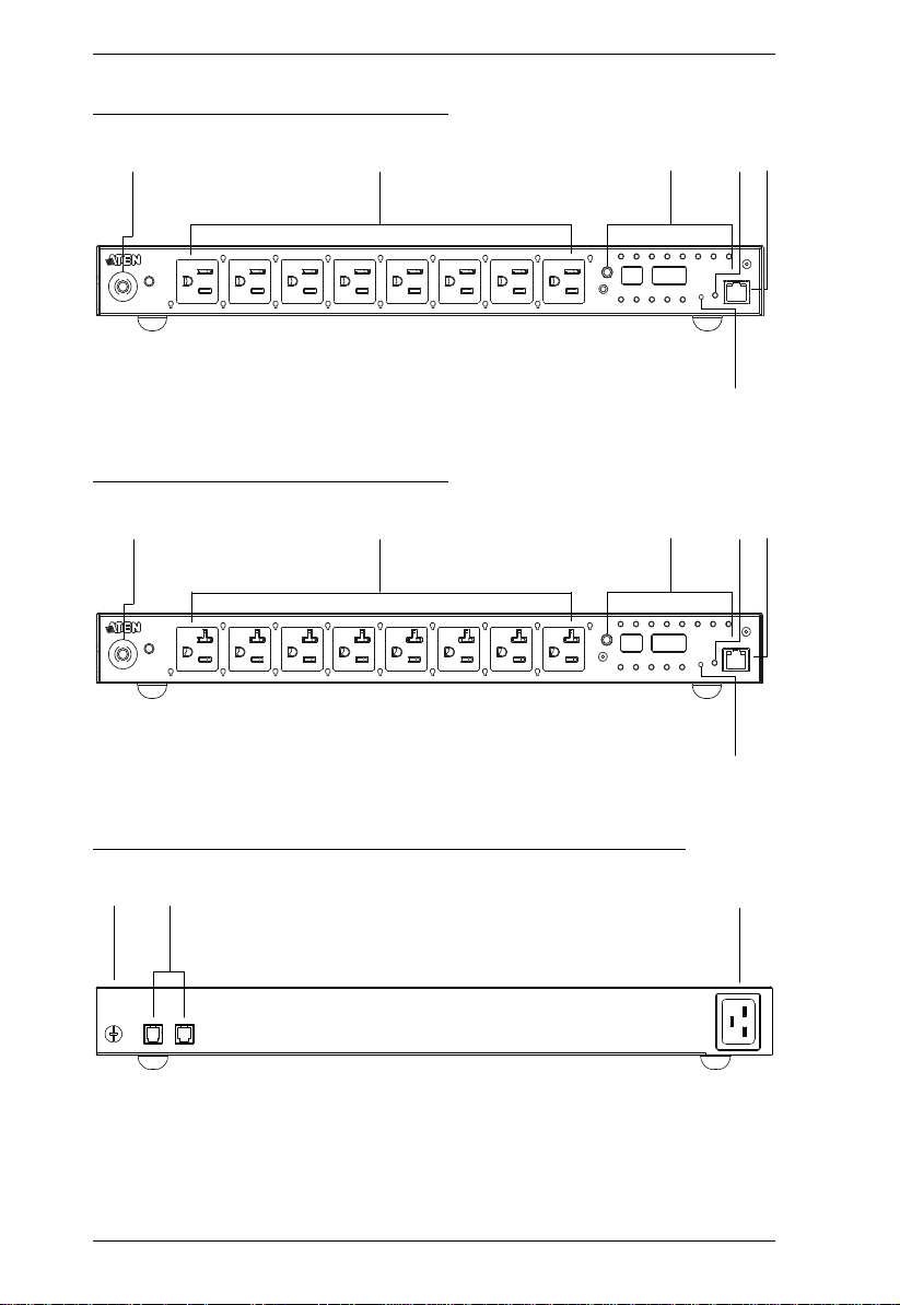
6
1
2
3
4
5
6
1
2
3
4
5
PE6108A / PE8108A Front View
PE6208A / PE8208A Front View
PE6108A / PE6208A / PE8108A / PE8208A Rear View
7
8
12
9
Page 25
Chapter 1. Introduction
3
SELECT
PDU
CURRENT
OUTLET
CURRENT
IP
ADDRESS
SENSOR
1
SENSOR
2
OUTLET STATUS
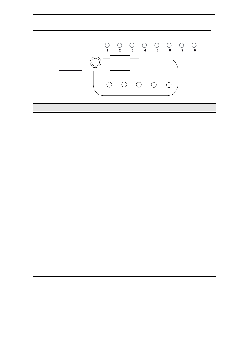
PE6108A / PE6208A / PE8108A / PE8208A Readout Section
No. Item Description
1 Circuit Breaker
Pushbutton
2 Power Sockets
3 Readout Section
4 Power LED
5 LAN Port and
LEDs
6 Reset Switch
Grounding Terminal The wire used to ground the unit connects here.
7
8 Sensor Ports
9 Power Socket
As a safety measure, if there is an overcurrent situation regarding the
device’s power, the circuit breakers will trip. Press the button to
recover normal operation.
8 x NEMA 5-15R or 8 x NEMA 5-20R
Note: Holes for ATEN Lok-U-Plug cable holders are located around
the sockets. See Securing the Cables, page 19, for further
information.
The selection (PDU Current / Outlet Current / IP Address) appears
in the first (1-digit) display window.
PDU Current / Outlet Current / IP Address appear in the second
(3-digit) display window
The LEDs above the items indicate which one the readout relates
to.
Press the button next to the first display window to cycle the
selection among the items.
The LED lights when the eco PDU is ready to operate.
The cable that connects the eco PDU to the LAN plugs in here. The
Link and LAN LEDs are built into the LAN port:
Link: Lights GREEN to indicate that a connection via the eco PDU's
RJ-45 Ethernet port has been established. Flashes to indicate data is
being transmitted.
LAN: Lights ORANGE to indicate 10 Mbps data transmission speed.
The LED lights GREEN to indicate 100 Mbps data transmission
speed.
This switch is recessed and must be pushed with a thin object, such
as the end of a paper clip.
Press and release to reboot the device.
Press and hold for more that three seconds to reset the eco
PDU to its factory default settings
External sensors plug into these two RJ-11 ports.
The power cord that connects the unit to an AC power source plugs
in here.
13
Page 26
eco PDU PE Series User Manual
6
1
2
3
4
5
6
1
2
3
4
5
8
9
7
PE6108B / PE6108G / PE8108B / PE8108G Front View
PE6208B / PE6208G / PE8208B / PE8208G Front View
PE6108B / PE6108G / PE6208B / PE6208G / PE8108B / PE8108G / PE8208B / PE8208G Rear View
14
Page 27
Chapter 1. Introduction
3
SELECT
PDU
CURRENT
OUTLET
CURRENT
IP
ADDRESS
SENSOR
1
SENSOR
2
OUTLET STATUS
PE6108B / PE6108G / PE6208B / PE6208G / PE8108B / PE8108G / PE8208B / PE8208G Readout Section
No. Item Description
1 Circuit Breaker
Pushbutton
2 Power Sockets
3 Readout Section
4 Power LED
5 LAN Port and
LEDs
6 Reset Switch
Grounding Terminal The wire used to ground the unit connects here.
7
8 Sensor Ports
9 Power Socket
As a safety measure, if there is an overcurrent situation regarding the
device’s power, the circuit breakers will trip. Press the button to
recover normal operation.
8 x IEC320 C13 or 7 x IEC320 C13 + 1 x C19
Note: Holes for ATEN Lok-U-Plug cable holders are located around
the sockets. See Securing the Cables, page 19, for further
information.
The selection (PDU Current / Outlet Current / IP Address) appears
in the first (1-digit) display window.
PDU Current / Outlet Current / IP Address appear in the second
(3-digit) display window
The LEDs above the items indicate which one the readout relates
to.
Press the button next to the first display window to cycle the
selection among the items.
Lights when the unit is powered up and ready to operate.
The cable that connects the eco PDU to the LAN plugs in here. The
Link and LAN LEDs are built into the LAN port:
Link: Lights GREEN to indicate that a connection via the eco PDU's
RJ-45 Ethernet port has been established. Flashes to indicate data is
being transmitted.
LAN: Lights ORANGE to indicate 10 Mbps data transmission speed.
The LED lights GREEN to indicate 100 Mbps data transmission
speed.
This switch is recessed and must be pushed with a thin object, such
as the end of a paper clip.
Press and release to reboot the device.
Press and hold for more that three seconds to reset the eco
PDU to its factory default settings
External sensors plug into these two RJ-11 ports.
The power cord that connects the unit to an AC power source plugs
in here.
15
Page 28

eco PDU PE Series User Manual
This Page Intentionally Left Blank
16
Page 29

Chapter 2
1. Important safety information regarding the placement of this device is
provided on page 59. Please review it before proceeding.
2. Make sure that power to all the devices you will be connecting have
been turned off. You must unplug the power cords of any computers
that have the Keyboard Power On function.
1. Vous trouverez des informations de sécurité importantes concernant le
positionnement de l’unité à la page 59. Veuillez les lire attentivement
avant d’aller plus loin.
2. Vérifiez que tous les périphériques à connecter sont éteints. Vous devez
débrancher les câbles d’alimentation des ordinateurs disposant de la
fonction de mise sous tension à partir du clavier.
Hardware Setup
Before You Begin
Rack Mounting
The eco PDU can be mounted in a 19” (1U) rack. To rack mount the device,
use the rack mounting brackets that came with your device. The brackets can
be screwed to the front or rear sides of the device, and then the unit can slide
into the front of the rack, as shown in the diagram below:
17
Page 30

eco PDU PE Series User Manual
Installation
To set up your eco PDU installation, refer to the installation diagram on the
next page (the numbers in the diagram correspond to the numbered steps), and
do the following:
1. Use a grounding wire to ground the eco PDU by connecting one end of the
wire to its grounding terminal, and the other end of the wire to a suitable
grounded object.
Note: Do not omit this step. Proper grounding helps to prevent damage to
the unit from surges or static electricity.
2. For each device you want to connect, use its power cable to connect from
the device's AC socket to any available outlet on the eco PDU.
3. Plug the cable that connects the eco PDU to the LAN into the eco PDU's
LAN port.
4. If you are using sensors in your eco PDU installation, connect them to the
sensor ports on the unit’s rear side panel.
Note: Sensors are optional. Please see Optional Accessories, page 7, and
the detailed sensor installation diagrams later in this chapter for
further information.
5. Connect the eco PDU's power cord to an AC power source.
Note: We strongly advise that you do not plug the eco PDU into a multi
socket extension cord, since it may not receive enough amperage to
operate correctly.
Once you have finished these installation steps, you can turn on the eco PDU
and the connected devices.
Note: We strongly recommend using cable ties and cable bars to safely and
securely route the cables attached to the front of the unit.
18
Page 31

Chapter 2. Hardware Setup
5
4
1
2
3
Securing the Cables
For added safety, use ATEN Lok-U-Plug cable holders to secure the cables
from your attached devices in place on the eco PDU unit. Secure the cable
holders using the specially designed holes around the individual power outlets,
as shown below:
Note: 1. Cable holders are an optional accessory. See Cable Holders, page 7.
2. Use only the ATEN Lok-U-Plug cable holders that have been
specifically designed to work with the eco PDU. Using any other kind
of cable securing device could be highly dangerous.
19
Page 32

eco PDU PE Series User Manual
Securing the Sensors
Connect the sensors to the eco PDU’s front panel sensor ports and secure them
using sensor mounts, tie wraps, and adhesive cable tie holders. If you use a tie
wrap to secure the sensor, tighten the tie wrap over the recessed channel on the
sensor, as shown in the following diagram:
Note: 1. The sensors shown in the above diagram are for reference purposes
only. The sensors for the eco PDU may look slightly different.
2. Depending on the model and type of sensor, sensor mounts, tie wraps,
and adhesive cable tie holders may or may not be provided in the
package.
20
Page 33

Chapter 3
Basic Operation and
First Time Setup
Operation Methods
NRGence eco PDU models provide three methods to access and manage your
installation: Browser, eco Sensors (eco PDU Management Software), and
SNMP.
Note: The following sections of this chapter contain information concerning
Browser operation. For eco Sensors operation, please reference the
separate eco Sensors User Manual. The eco Sensors software and User
Manual can be downloaded from the ATEN website.
Browser
The eco PDU can be accessed and controlled via any supported Internet
browser from any platform. See First Time Setup, page 22, and the following
sections in this chapter, for full details.
eco Sensors
The eco PDU supports NRGence eco Sensors (eco PDU Manager Software).
NRGence eco Sensors provides you with an easy method for managing
multiple devices, offering an intuitive and user-friendly Graphical User
Interface that allows you to configure a PDU device and monitor power status
of the equipment connected to it. NRGence eco Sensors can be downloaded
from the ATEN website, along with a separate eco Sensors User Manual.
SNMP
The eco PDU supports any 3rd party V3 SNMP Manager Software. SNMP
Management Information Database (MIB) files for the eco PDU device can be
found on the software CD provided with the eco PDU package.
21
Page 34

eco PDU PE Series User Manual
First Time Setup
Once the eco PDU installation has been cabled up, the next task the
Administrator needs to perform involve configuring the network parameters,
changing the default Super Administrator login settings, and adding users.
The way to accomplish this is to log in over the Net with a browser.
Note: 1. Since this is the first time you are logging in, use the default
Username: administrator; and the default Password: password. For
security purposes we recommend changing them to something unique
(see Changing the Administrator Login, page 24).
2. For remote methods of getting lo gged in to the network, see IP
Address Determination, page 68.
After you successfully log in, the eco PDU Energy/Connections page appears:
Note: Operation details are discussed in Energy, page 28, in the next chapter.
For further setup information, continue with this chapter
22
Page 35

Chapter 3. Basic Operation and First Time Setup
Network Configuration
To set up the network, do the following:
1. Click the Setup tab.
2. The interface displays the Device Configuration page. A screen similar to
the one below appears:
3. Fill in the fields according to the information provided under Device
Configuration, page 38.
23
Page 36

eco PDU PE Series User Manual
Changing the Administrator Login
To change the default Administrator username and password, do the following:
1. Click the User tab.
The Accounts page has a detailed list of users – with more information
about them – in the large central panel:
2. In the Administrator Information section, reset the name and password
fields to something unique, then click Save (at the bottom of the page.)
Note: If you forget the Administrator’s name or password, short the
mainboard jumper to restore the default Administrator account. See see
Administrator Login Failure, page 76 in the Appendix for full details.
Moving On
After setting up the network and changing the default Administrator username
and password, you can proceed to other administration activities – including
adding users. This is covered in the next chapter.
24
Page 37

Chapter 4
Browser Operation
Logging In
The eco PDU can be accessed via a supported Internet browser from any
platform.
Note: Browsers must support SSL 128 bit encryption.
To access the eco PDU do the following:
1. Open your browser and specify the IP address of the eco PDU you want to
access in the browser's URL location bar.
Note: You can get the IP address from the eco PDU administrator, or see
IP Address Determination, page 68, for information about setting it
up yourself.
2. If a Security Alert dialog box appears, accept the certificate – it can be
trusted. The Login page appears:
3. Provide a valid Username and Password (set by the eco PDU
administrator), and select your language. (Options are: English [default];
Traditional Chinese; Simplified Chinese; Japanese; German; Italian;
Spanish; French).
4. Then Click Login to bring up the browser Main Page.
25
Page 38

eco PDU PE Series User Manual
The eco PDU Main Page
After you have successfully logged in, the eco PDU Main Page comes up with
the Energy Connections page displayed:
Note: The screen depicts an Administrator’s page. Depending on a user’s type
and permissions, not all of these elements appear.
26
Page 39

Chapter 4. Browser Operation
Page Components
The web page screen components are described in the table, below:
No. Item Description
1 Tab Bar The tab bar contains the eco PDU’s main operation
2 Menu Bar The menu bar contains operational sub-categories
3 Sidebar The Sidebar provides a tree view listing of outlets
4 Help Connects to on-line help at the ATEN website for the
5 Logout Click this button to log out of your eco PDU session.
6 Interactive Display Panel This is your main work area. The screens that
categories. The items that appear in the tab bar are
determined by the user’s type, and the authorization
options that were selected when the user’s account
was created.
that pertain to the item selected in the tab bar. The
items that appear in the menu bar are determined by
the user’s type, and the authorization options that
were selected when the user’s account was created.
that relate to the various tab bar and menu bar
selections.
device’s configuration and operation.
appear reflect your menu choices and Sidebar node
selection.
27
Page 40

eco PDU PE Series User Manual
Energy
Connections
When you log in to the eco PDU, the interface opens with its default selection
of the Energy tab; and the Connections menu. The contents of the PDU Status
and Outlet Status sections are displayed in the main panel.
Note: Only enabled eco PDU models will display the Outlet Status submenu
section. Other models provide only PDU Status monitoring. See PE
Series eco PDU Comparison Chart, page 3, for which models support
PDU and Outlet Status or PDU Status only monitoring.
28
Page 41

Chapter 4. Browser Operation
PDU Status
All eco PDU models support PDU device level monitoring. The PDU Status
section allows you to set up a power management configuration for the PDU
device as a whole:
PDU Threshold Settings
These fields are used to set the maximum, minimum, and fluctuation
threshold settings for Aggregate Current, Voltage, Power, and Aggregate
Power Dissipation. If a range falls below the minim um set ting, or exceeds
the maximum setting an alarm is triggered.
Breaker status (ON / OFF) displays here.
Voltage Frequency is displayed here in Hz.
On / Off / Reboot
You can manually turn the device On and Off from this page by clicking
the radio buttons. To Reboot the device, enable the Reboot checkbox and
click on Save (located at the bottom of the page).
Sensor 1 / Sensor 2
If you have sensors installed in your installation, use these fields to set the
maximum, minimum, and fluctuation threshold settings for Temperature,
Humidity, and Differential Pressure.
Note: Sensors are optional accessories. Check with your dealer for
information about NRGence eco Sensors software.
29
Page 42

eco PDU PE Series User Manual
Outlet Status
If your eco PDU models supports outlet level monitoring, the main panel
Outlet Status section allows you to set up a power management configuration
for each outlet at an individual level.
Outlet Threshold Settings
These fields are used to set the maximum, minimum, and fluctuation
threshold settings for Current, Voltage, Power, and Power Dissipation. If a
range falls below the minimum setting, or exceeds the maximum setting an
alarm is triggered.
On / Off / Reboot
Y ou can manually turn the outlet On and Off from this page by clicking the
radio buttons. To Reboot the outlet, enable the Reboot checkbox and click
on Save (located at the bottom of the page).
30
Page 43

Chapter 4. Browser Operation
Configuration
The Configuration page is used to configure the settings of the eco PDU at the
individual power outlet level:
POP Settings
This section allows you to configure the settings for the Proactive
Overload Protection (POP) feature. Effective on all non-critical outlets,
this added safety feature automatically powers off the last outlet that
caused the current overload.
Enable POP Mode by clicking the radio button
Make your selection for the POP Threshold – options are Same as Bank
Maximum Current or User Defined – Enter a value in the field.
Note: This feature is available on the PE8108 and PE8208 models only.
(Continues on next page.)
31
Page 44

eco PDU PE Series User Manual
Power On Time Schedule Settings
Check the Enable Power On Time Schedule box to use the Power ON
Delay setting to set the amount of time the eco PDU waits before powering
on an outlet. See Power ON Delay in the table below.
Buzzer Setting
Checking the Enable Buzzer Alarm box sounds an alarm and sends
SNMP trap or e-mail alerts when a circuit breaker trips or a PDU/Outlet
threshold setting exceeds the minimum or maximum setting.
Outlet Configuration
The Outlet Configuration section lets you set the power management settings
for each outlet on the PDU.
Heading Meaning
Outlet Name Each outlet can be given a distinctive name. The maximum
Confirmation
Required
Power ON Delay Sets the amount of time the eco PDU waits after the Power Button
Power OFF Delay Sets the amount of time the eco PDU waits after the Power Button
number of characters is 15.
If this option is enabled (there is a check in the checkbox), a dialog
box comes up asking you to confirm a power operation before it is
performed. If it is disabled (there is no check in the checkbox), the
operation is performed without confirmation.
is clicked (see Outlet Status, page 30), before it turns on the power
to the outlet. You must check the Enable Power On Time Schedule
Setting box for this setting to take effect. See Power On Time
Schedule Settings, page 32, for details.
Note: The default delay time is 0 seconds; the maximum is 999 seconds.
When a series of outlets are scheduled to be powered up, they turn on in
sequence with a default delay of 10 milliseconds between each outlet.
is clicked (see Outlet Status, page 30), before it turns off the power
to the outlet.
For the System after AC Back option (see below), after the delay
time expires, the eco PDU waits another fifteen seconds, then
shuts the computer down.
The default delay time is 15 seconds. The maximum delay time is
999 seconds.
32
Page 45

Chapter 4. Browser Operation
Heading Meaning
Remote Turn ON
Method
Use the drop-down menu to select one of the choices, below:
Wake on LAN: This is a Safe Shutdown and Restart option. If this
is selected, when an Outlet is turned Off, the eco PDU first sends
a message to the computer telling it to prepare for a shutdown; it
then waits for the amount time set in the Power Off Delay field to
give the OS time to close down before the computer is powered
down to standby mode.
Likewise, when the Outlet is turned On, the eco PDU waits for
the amount time set in the Power On Delay field, then sends an
Ethernet message to the computer connected to the Outlet
telling the computer to turn itself On.
Note: For Safe Shutdown and Restart, the computer must be running
Windows (98 or higher), or Linux, and the Safe Shutdown program
(available by download from our website), must be installed and running
on the computer.
System after AC Back: This is a Safe Shutdown and Restart
option. If this is selected, when an Outlet is turned Off, the eco
PDU first sends a message to the computer telling it to prepare
for a shutdown; it then waits for the amount time set in the Power
Off Delay field to give the OS time to close down before the
computer is powered down.
When the Outlet is turned On, the eco PDU waits for the amount
time set in the Power On Delay field, then sends power to the
server. When the server receives the power, it turns itself on.
Note: For Safe Shutdown and Reboot, the computer must be running
Windows (98 or higher), or Linux, and the Safe Shutdown program
(available by download from our website), must be installed and running
on the computer.
Kill the Power: If this option is selected, the eco PDU waits for the
amount time set in the Power Off Delay field, and then turns the
Outlet's power Off. Turning the power off performs a cold (nonsafe) shutdown.
MAC Address In order to use either of the Safe Shutdown and Restart methods
the MAC address of the computer connected to the outlet must be
filled in here.
When you have finished making your configuration settings, click Save.
33
Page 46

eco PDU PE Series User Manual
User
When you select the User tab the screen comes up with Administrator
Information and User Information displayed in the main panel. The eco PDU
supports one Administrator account and up to eight User accounts.
Note: 1. Each account can support 2 login sessions
2. The eco PDU supports a total of 3 concurrent login sessions.
Note: There is a pre-installed administrator account. It can be used to set up
the device and to begin creating users and groups. The Username for
this account is administrator; the password is password. For security
purposes, we strongly recommend changing these to something unique.
Administrator Information
This section is used to set the Administrator name and password. Only
Administrators can view this section. For details, see Changing the
Administrator Login, page 24.
SNMPv3 Account Information
Enter values for Name, Auth-Password and Priv-Password for SNMPv3
authentication, if required.
SNMPv1/V2c Community
Enter values Read community and Write community for SNMPv1/V2c
authentication, if required.
34
Page 47

Chapter 4. Browser Operation
User Information
To add a user, do the following:
1. Select the user type in the Management drop-down menu.
2. Key in a name and password in the Name and Password fields.
3. Set the outlet-by-outlet permissions of the user in the Outlet field.
4. Set the Management field to Enable.
5. Click Save to save your settings.
Note: Va lu es must be entered in both the Name and Password fields in
order to enable an account.
The various options are explained in more detail in the following table:
Field Description
Management The Management field allows you to Enable or Disable a
Name From 1 to 16 characters are allowed depending on the
Password From 1 to 16 characters are allowed depending on the
Outlet This field allows you to set the outlet-by-outlet permissions of
user’s account:
Enable – stores the user account (see User Information,
page 35
Disable – disables the user account
Account Policy settings. See Account Policy, page 48.
Account Policy settings. See Account Policy, page 48.
the user. Click on the user/port icon to cycle through the three
permissions options, as follows:
User has complete access to this outlet.
User has read-only access to this outlet.
User has no access to this outlet.
Save Click this button to save your operation or changes
35
Page 48

eco PDU PE Series User Manual
Log
The Log tab keeps a record of transactions that take place on its installation,
and stores up to 128 events at one time. The System Log page provides a
powerful array of filters and functions that allow you to view and export the log
file data, as well as be informed by email of specified events as they occur.
The System Log Event List
Clicking on a device in the Sidebar displays its log events in the main
panel’s log event list.
Clicking the Refresh button brings the log list up to date with the latest
events.
The entry box to the right of the Refresh button lets you set the number of
events to display per page. Simply key in the number of your choice.
The top right of the main panel shows the total number of pages in the log
file, and what page you are currently viewing.
The buttons on the bottom row function as follows:
Clear – click to erase the contents of the log event list
First Page – click to go to the first page of the log event list
Previous Page – click to move to the previous page of the log event
list
Next Page – click to move to the next page of the log event list
Last Page – click to move to the last page of the log event list
Export Log – click to save the contents of the log event list to file.
36
Page 49

Chapter 4. Browser Operation
Notification Settings
The Notification Settings page is used to specify which of the eco PDU’s
components will receive notification of a log event. When you click the
Notification Settings menu item, a page similar to the one below appears:
The event categories are listed in the left column.
When you first open the page, only the main category items appear.
(Main category item rows have a gray background.)
Sub-category items are nested under the main category headings. Click
the arrow in front of the main category headings to display the
subcategory items. (Sub-category item rows have a white background.)
Click the checkboxes under the column headings to select which
component(s) will receive notification of the log events.
Clicking on a main category heading’s row automatically selects all the
sub-category items nested below it.
If you only want to set notification for some of the sub-category
events, don’t put a check in the main category row . Instead, drop down
the sub-category list, and only check the sub-category events you want.
When you have finished making your setting choices, click Save. When a
specified log event occurs, notification of that event will be sent to the
selected component.
Reset Digital Output: If an event has been triggered that changes the
digital output sensor from Low to High, click this button to return the
sensor to the Low state.
37
Page 50

eco PDU PE Series User Manual
Setup
The Setup tab provides Device Configuration and Security settings. The Device
Configuration page allows super administrators, administrators, and users with
device management permission to configure eco PDU system settings. The
Security page controls access to the PDU.
Device Configuration
This page presents information about the selected device, as described in the
following sections:
General
Item Meaning
PDU Name This field lets you give the device a unique name. Simply delete
whatever is in the text box and key in the name of your choice.
Click Save (located at the bottom of the page) to save the new
name.
MAC Address This item displays the eco PDU’s MAC address.
Firmware Version This item displays the current firmware version number. You can
reference it to see if there are newer versions available on the
NRGence website.
Rack Location
Name
38
This field lets you give the rack location a unique name for easy
reference.
Page 51

Chapter 4. Browser Operation
Service Ports
As a security measure, if a firewall is being used, the Administrator can specify
the port numbers that the firewall will allow. If a port other than the default is
used, users must specify the port number as part of the IP address when they
log in. If an invalid port number (or no port number) is specified, the eco PDU
will not be found.
Select whether to allow only secure browser logins, as show below:
An explanation of the fields is given in the table below:
Field Explanation
HTTP The port number for a browser login. The default is 80.
HTTPS The port number for a secure browser login. The default is 443.
Note: 1. Valid entries for all of the Service Ports are from 1–65535.
2. The service ports cannot have the same value. You must set a
different value for each one.
3. If there is no firewall (on an Intranet, for example), it doesn’t matter
what these numbers are set to, since they have no effect.
39
Page 52

eco PDU PE Series User Manual
IPv4 Configuration
The PDU’s IPv4 IP and DNS addresses (the traditional method of specifying
IP addresses) can either be assigned dynamically (DHCP), or a fixed IP address
can be specified.
For dynamic IP address assignment, select the Obtain IP address
automatically radio button. (This is the default setting.)
To specify a fixed IP address, select the Set IP address manually radio
button and fill in the IP address with values appropriate for your network.
For automatic DNS Server address assignment, select the Obtain DNS
Server address automatically radio button.
To specify the DNS Server address manually, select the Set DNS server
address manually radio button, and fill in the addresses for the Preferred
and Alternate DNS servers with values appropriate for your network.
Note: 1. If you choose Obtain IP address automatically, when the device starts
up it waits to get its IP address from the DHCP server. If it hasn’t
obtained the address after one minute, it automatically reverts to its
factory default IP address (192.168.0.60.)
2. If the device is on a network that uses DHCP to assign network
addresses, and you need to ascertain its IP address, see IP Address
Determination, page 68, for information.
3. Specifying the Alternate DNS Server address is optional.
40
Page 53

Chapter 4. Browser Operation
IPv6 Configuration
IPv6 is the new (128-bit) format for specifying IP addresses. The PDU°¶s IPv6
IP and DNS addresses can either be assigned dynamically (DHCP), or a fixed
IP address can be specified.
For IP address assignment, select the Enable autoconfiguration radio
button. (This is the default setting.)
To specify a fixed IP address, select the Set configuration manually radio
button and fill in the IP address with values appropriate for your network.
For automatic DNS Server address assignment, select the Use DHCPv6 to
obtain DNS Server Addresses radio button.
To specify the DNS Server address manually, select the Set DNS server
address manually radio button, and fill in the addresses for the Preferred
and Alternate DNS servers with values appropriate for your network.
Note: 1. If you choose Enable autoconfiguration , when the device starts up it
waits to get its IP address. If it hasn’t obtained the address after one
minute, it automatically reverts to its factory default IP address
(192.168.0.60.)
2. If the device is on a network that uses DHCP to assign network
addresses, and you need to ascertain its IP address, see IP Address
Determination, page 68, for information.
3. Specifying the Alternate DNS Server address is optional.
41
Page 54

eco PDU PE Series User Manual
Event Notification
The Event Notification section is divided into three sections: SMTP Settings;
SNMP Trap Receivers; and Syslog Server. Each section is described below.
SMTP Settings
To have the eco PDU device email reports from the SMTP server to you, do
the following:
1. Enable the Enable report from the following SMTP server, and key in the
IP address of your SMTP server.
2. If your server requires authentication, put a check in the My server
requires authentication checkbox.
3. Key in the appropriate account information in the Account Name,
Password, and From fields.
Note: Only one email address is allowed in the From fields, and it cannot
exceed 64 characters.)
4. Key in the email address (addresses) of where you want the event reports
sent to in the To field.
Note: If you are sending the report to more than one email address,
separate the addresses with a semicolon. The total cannot exceed
256 characters.
42
Page 55

SNMP Trap Receivers
Chapter 4. Browser Operation
Up to four SNMP management stations can be specified. If you want to use
SNMP trap notifications, do the following:
1. Check Enable SNMP Trap.
2. Select which version of SNMP you want to use.
3. Key in the IP address(es) and the service port number(s) of the
computer(s) to be notified of SNMP trap events. The valid port range is
1–65535. The default port number is 162.
Note: Make sure that the port number you specify here matches the port
number used by the SNMP receiver computer.
4. Key in the community value(s) if required for the SNMP version.
5. Key in the auth/privacy password(s) that correspond to each of the
stations.
43
Page 56

eco PDU PE Series User Manual
Syslog Server
To record all the events that take place on eco PDU devices and write them to
the eco PDU Syslog server, do the following:
1. Check Enable Syslog Server.
2. Key in the IP address and the port number of the Syslog server. The valid
port range is 1-65535. The default port number is 514.
44
Page 57

Chapter 4. Browser Operation
Date/Time
The Date/Time dialog page sets the eco PDU time parameters:
Time Zone
To establish the time zone that the eco PDU is located in, drop down the
Time Zone list and choose the city that most closely corresponds to where
it is at.
If your country or region employs Daylight Saving Time (Summer Time),
check the corresponding checkbox.
45
Page 58

eco PDU PE Series User Manual
Manual Input
Use this section to specify the eco PDU’s date and time manually.
Click the calendar icon and click the calendar entry for the date.
Key the time into the Time field, using the HH:MM:SS (hours, minutes,
seconds) format.
Note: This section is only enabled when auto adjustment (in the Network Time
section) is disabled (the checkbox is unchecked).
As an alternative to specifying the date and time by entering them into the date
and time fields, you can click to put a check in the Sync with PC checkbox, in
which case the eco PDU will take its date and time settings from the locally
connected PC.
Network Time
To have the time automatically synchronized to a network time server, do the
following:
1. Check the Enable auto adjustment checkbox.
2. Drop down the time server list to select your preferred time server
– or –
Check the Preferred custom server IP checkbox, and key in the IP address
of the time server of your choice.
3. If you want to configure an alternate time server, check the Alternate time
server checkbox, and repeat step 2 for the alternate time server entries.
4. Key in your choice for the number of days between synchronization
procedures.
Finishing Up
When you have finished making your settings on this page, click Save.
After you have saved your changes, if you want to synchronize immediat ely,
click Adjust Time Now.
46
Page 59

Chapter 4. Browser Operation
Security
The Security page controls access to the eco PDU device.
Login Failures
Allowed sets the number of consecutive failed login attempts that are
permitted from a remote user.
Timeout sets the amount of time a remote user must wait bef or e
attempting to login again after exceeding the number of allowed failures.
Working Mode
If ICMP is enabled, the eco PDU device can be pinged. If it is not
enabled, the device cannot be pinged. The default is Enabled.
When you have finished making your settings on this page, click Save.
47
Page 60

eco PDU PE Series User Manual
Account Policy
The Account Policy section governs policies in regard to usernames and
passwords.
Check a policy and enter the required information in the appropriate fields.
Item Description
Minimum Username Length Sets the minimum number of characters required for
a username. Acceptable values are from 1–16.
Minimum Password Length Sets the minimum number of characters required for
a password. Acceptable values are from 1–16.
Password Must Contain At Least Checking any of these items requires users to include
Disable Duplicate Login Check this to prevent users from logging in with the
at least one of the specified items in their password.
Note: This policy does not affect existing user
accounts. Only new user accounts created after this
policy has been enabled, and users required to
change their passwords are affected.
same account at the same time.
48
Page 61

Login String / IP Filter / Mac Filter
Chapter 4. Browser Operation
Login String
The Login String entry field is used to specify a login string (in addition to the
IP address) that users must include when accessing the eco PDU device with a
browser. For example:
192.168.0.126/abcdefg
The following characters are allowed:
0–9 a–z A–Z ~ ! @ $ * ( ) _ ‘ ,
The following characters are not allowed:
& ^ { } ‘ ’ < > | " % ” : / ? # \ [Space] + - = [ ] ;
Compound characters (É Ç ñ ... etc.)
Note: 1. There must be a forward slash between the IP address and the string.
2. If no login string is specified here, anyone will be able to access the
eco PDU device login page using the IP address alone. This makes
your installation less secure.
For security purposes, we recommend that you change this string occasionally.
49
Page 62

eco PDU PE Series User Manual
IP Filter / MAC Filter
If any filters have been configured, they appear in the IP Filter and/or MAC
Filter list boxes.
IP and MAC Filters control access to the eco PDU based on the IP and/or MAC
addresses of the client computers attempting to connect. A maximum of 5 IP
filters and 5 MAC filters are allowed.
To enable IP and/or MAC filtering, click to put a check mark in the IP Filter
Enable and/or MAC Filter Enable checkbox.
If the include button is checked, all the addresses within the filter range are
allowed access; all other addresses are denied access.
If the exclude button is checked, all the addresses within the filter range
are denied access; all other addresses are allowed access.
Adding Filters
To add an IP filter, do the following:
1. Click Add. A dialog box similar to the one below appears:
2. Specify the start filter address in the dialog box (for example,
192.168.0.200), then click OK.
3. To filter a single IP address, key in the same address as the start IP. To
filter a continuous range of addresses, key in the end number of the range
(for example, 192.168.0.225).
4. After filling in the address, click OK.
Repeat these steps for any additional IP addresses you want to filter.
50
Page 63

Chapter 4. Browser Operation
To add a MAC filter, do the following:
1. Click Add. A dialog box similar to the one below appears:
2. Specify the MAC address in the dialog box (for example, 001074670000),
then click OK.
Repeat these steps for any additional MAC addresses you want to filter.
IP Filter / MAC Filter Conflict
If there is a conflict between an IP filter and a MAC filter – for example, where
a computer’s IP address is allowed by the IP filter but its MAC address is
excluded by the MAC filter – then that computer’s access is blocked.
In other words, if either filter blocks a computer, then the computer is blocked,
no matter what the other filter is set to.
Modifying Filters
To modify a filter, select it in the IP Filter or MAC Filter list box and click
Modify. The Modify dialog box is similar to the Add dialog box. When it
comes up, simply delete the old address(es) and replace it with the new one(s).
Deleting Filters
To delete a filter, select it in the IP Filter or MAC Filter list box and click
Delete.
51
Page 64

eco PDU PE Series User Manual
Authentication & Authorization
The Authentication & Authorization page is used to set up login authentication
and authorization management from external sources.
RADIUS Settings
To allow authentication and authorization for the eco PDU device through a
RADIUS server, do the following:
1. Check Enable.
2. Fill in the IP addresses and service port numbers for the Preferred and
Alternate RADIUS servers. The default port number for the Preferred
server is 1812; the default port number for the Alternate server is 1645.
Note: Make sure that the port numbers you specify here match the port
numbers used by the RADIUS servers.
3. In the Timeout field, set the time in seconds that the eco PDU device waits
for a RADIUS server reply before it times out.
4. In the Retries field, set the number of allowed retries for attempting to
connect to the RADIUS server.
5. In the Shared Secret field, key in the character string that you want to use
for authentication between the eco PDU device and the RADIUS Server.
52
Page 65

Chapter 4. Browser Operation
6. On the RADIUS server, set the entry for each user as follows:
su/administrator or su/user
Where xxxx represents the Username given to the user when the account
was created on the eco PDU device. The user’s access rights are the ones
assigned for the eco PDU device, as well. (See User Information,
page 35.)
Note: su/user supports view ports only; su/administrator supports all eco PDU
functions.
Private Certificate
When logging in over a secure (SSL) connection, a signed certificate is used to
verify that the user is logging in to the intended site. For enhanced security, the
Private Certificate section allows you to use your own private encryption key
and signed certificate, rather than the default ATEN certificate.
There are two methods for establishing your private certificate: generating a
self-signed certificate; and importing a third-p a rty certificate authority (CA)
signed certificate.
Generating a Self-Signed Certificate
If you wish to create your own self-signed certificate, a free utility –
openssl.exe – is available for download over the web.
Obtaining a CA Signed SSL Server Certificate
For the greatest security, we recommend using a third party certificate
authority (CA) signed certificate. To obtain a third party signed certificate, go
to a CA (Certificate Authority) website to apply for an SSL certificate. After
the CA sends you the certificate and private encryption key, save them to a
convenient location on your computer.
(Continues on next page.)
53
Page 66

eco PDU PE Series User Manual
Importing the Private Certificate
To import the private certificate, do the following:
1. Click Browse to the right of Private Key; browse to where your private
encryption key file is located; and select it.
2. Click Browse to the right of Certificate; browse to where your certificate
file is located; and select it.
3. Click Upload to complete the procedure.
Note: 1. Clicking Restore Default returns the device to using the default
ATEN certificate.
2. Both the private encryption key and the signed certificate must be
imported at the same time.
When you have finished making your settings on this page, click Save.
54
Page 67

Chapter 4. Browser Operation
PDU
The PDU tab is used to upgrade the eco PDU’s firmware, and to backup and
restore the device’s configuration settings.
Firmware File
When you click the Maintenance tab, the display opens with the Firmware
Upgrade menu page, which looks similar to the one below:
A description of the items shown in this panel are given in the table, below:
Item Description
Check Main
Firmware Version
Name Lists all of the eco PDU devices. Click to put a check in the
F/W Version Displays the eco PDU’s current firmware version.
Filename As new versions of the firmware become available, they are
Upgrade Click this button to upgrade the firmware of the selected devices.
If you enable Check Main Firmware Version, the eco PDU’s
current firmware level is compared with that of the upgrade file. If
the current version is equal to or higher than the upgrade version,
a popup message appears, to inform you of the situation and stops
the upgrade procedure.
checkbox of the device’s whose firmware you want to upgrade.
posted on our website and can be downloaded to a convenient
location on your computer. Click the Browse button to select the
downloaded upgrade file.
55
Page 68

eco PDU PE Series User Manual
Upgrading the Firmware
To upgrade the firmware refer to the screenshot on the preceding page, and do
the following:
1. Go to our website and download the new firmware file to a convenient
location on your computer.
2. Click the Browse button; navigate to where the firmware file is located and
select it.
3. Click Upgrade to start the upgrade procedure.
If you enabled Check Main Firmware Version the current firmware
level is compared with that of the upgrade file. If the current version is
equal to or higher than the upgrade version, a popup message appears,
to inform you of the situation and stops the upgrade procedure.
If you didn't enable Check Main Firmware Version, the upgrade file is
installed without checking what its level is.
Once the upgrade completes successfully, the switch resets itself.
4. Log in again, and check the firmware version to be sure it is the new one.
Firmware Upgrade Recovery
Should the eco PDU’s firmware upgrade procedure fail, and the device
becomes unusable, the following firmware upgrade recovery procedure will
resolve the problem:
1. Power off the device.
2. Press and hold the Reset Switch in (see page 13).
3. While holding the Reset Switch in, power the switch back on.
This causes the switch to use the original factory installed main firmware
version. Once the switch is operational, you can try upgrading the main
firmware again.
56
Page 69

Chapter 4. Browser Operation
Backup/Restore
Selecting Backup/Restore on the menu bar gives you the ability to back up the
switch’s configuration and user profile information:
Backup
To backup the device’s settings do the following:
1. In the Password field, key in a password for the file.
Note: Entering a password is optional. If you do enter a password, make a
note of it, since you will need it to be able to restore the file.
2. Click Save.
3. When the browser asks what you want to do with the file, select Save to
disk; then save it in a convenient location.
Restore
To restore a previous backup, do the following:
1. Click Browse; navigate to the file and select it.
Note: If you renamed the file, you can leave the new name. There is no
need to return it to its original name.
2. In the Password field, key in the same password that you used to save the
file.
Note: If you did not set a password when you created the backup file, you
can omit this step.
3. Select as many of the options that are presented as you wish to restore.
4. Click Restore.
After the file is restored, a message appears to inform you that the
procedure succeeded.
57
Page 70

eco PDU PE Series User Manual
This Page Intentionally Left Blank
58
Page 71

Appendix
Safety Instructions
General
This product is for indoor use only.
Read all of these instructions. Save them for future reference.
Follow all warnings and instructions marked on the device.
Do not place the device on any unstable surface (cart, stand, table, etc.). If
the device falls, serious damage will result.
Do not use the device near water.
Do not place the device near, or over, radiators or heat registers.
The device cabinet is provided with slots and openings to allow for
adequate ventilation. To ensure reliable operation, and to protect against
overheating, these openings must never be blocked or covered.
The device should never be placed on a soft surface (bed, sofa, rug, etc.) as
this will block its ventilation openings. Likewise, the device should not be
placed in a built in enclosure unless adequate ventilation has been
provided.
Never spill liquid of any kind on the device.
Unplug the device from the wall outlet before cleaning. Do not use liquid
or aerosol cleaners. Use a damp cloth for cleaning.
The device should be operated from the type of power source indicated on
the marking label. If you are not sure of the type of power available,
consult your dealer or local power company.
To prevent damage to your installation it is important that all devices are
properly grounded.
The device is equipped with a 3-wire grounding type plug. This is a safety
feature. If you are unable to insert the plug into the outlet, contact your
electrician to replace your obsolete outlet. Do not attempt to defeat the
purpose of the grounding-type plug. Always follow your local/national
wiring codes.
The equipment should be installed near the wall socket outlet and the
disconnect device (appliance coupler) should be readily accessible.
Do not allow anything to rest on the power cord or cables. Route the
power cord and cables so that they cannot be stepped on or tripped over.
59
Page 72

eco PDU PE Series User Manual
To help protect your system from sudden, transient increases and
decreases in electrical power, use a surge suppressor, line conditioner, or
uninterruptible power supply (UPS).
Position system cables and power cables carefully; Be sure that nothing
rests on any cables.
When connecting or disconnecting power to hot pluggable power supplies,
observe the following guidelines:
Install the power supply before connecting the power cable to the
power supply.
Unplug the power cable before removing the power supply.
If the system has multiple sources of power, disconnect power from the
system by unplugging all power cables from the power supplies.
Never push objects of any kind into or through cabinet slots. They may
touch dangerous voltage points or short out parts resulting in a risk of fire
or electrical shock.
Do not attempt to service the device yourself. Refer all servicing to
qualified service personnel.
If the following conditions occur, unplug the device from the wall outlet
and bring it to qualified service personnel for repair.
The power cord or plug has become damaged or frayed.
Liquid has been spilled into the device.
The device has been exposed to rain or water.
The device has been dropped, or the cabinet has been damaged.
The device exhibits a distinct change in performance, indicating a need
for service.
The device does not operate normally when the operating instructions
are followed.
Only adjust those controls that are covered in the operating instructions.
Improper adjustment of other controls may result in damage that will
require extensive work by a qualified technician to repair.
Do not connect the RJ-11 connector marked “Sensor” to a public
telecommunication network.
60
Page 73

Appendix
Consignes de sécurité
Général
Ce produit est destiné exclusivement à une utilisation à l’intérieur.
Veuillez lire la totalité de ces instructions. Conservez-les afin de pouvoir
vous y référer ultérieurement.
Respectez l’ensemble des avertissements et instructions inscrits sur
l’appareil.
Ne placez jamais l’unité sur une surface instable (chariot, pied, table, etc.).
Si l’unité venait à tomber, elle serait gravement endommagée.
N’utilisez pas l’unité à proximité de l’eau.
Ne placez pas l’unité à proximité de ou sur des radiateurs ou bouches de
chaleur.
Le boîtier de l’unité est doté de fentes et d’ouvertures destinées à assurer
une ventilation adéquate. Pour garantir un fonctionnement fiable et
protéger l’unité contre les surchauffes, ces ouvertures ne doivent jamais
être bloquées ou couvertes.
L’unité ne doit jamais être placée sur une surface molle (lit, canapé, tapis,
etc.) car ses ouvertures de ventilation se trouveraient bloquées. De même,
l’unité ne doit pas être placée dans un meuble fermé à moins qu'une
ventilation adaptée ne soit assurée.
Ne renversez jamais de liquides de quelque sorte que ce soit sur l’unité.
Débranchez l’unité de la prise murale avant de la nettoyer. N’utilisez pas
de produits de nettoyage liquide ou sous forme d’aérosol. Utilisez un
chiffon humide pour le nettoyage de l’unité.
L’appareil doit être alimenté par le type de source indiqué sur l’étiquette.
Si vous n’êtes pas sûr du type d’alimentation disponible, consultez votre
revendeur ou le fournisseur local d’électricité.
Afin de ne pas endommager votre installation, vérifiez que tous les
périphériques sont correctement mis à la terre.
L’unité est équipée d’une fiche de terre à trois fils. Il s’agit d’une fonction
de sécurité. Si vous ne parvenez pas à insérer la fiche dans la prise murale,
contactez votre électricité afin qu’il remplace cette dernière qui doit être
obsolète. N’essayez pas d’aller à l’encontre de l’objectif de la fiche de
terre. Respectez toujours les codes de câblage en vigueur dans votre
région/pays.
61
Page 74

eco PDU PE Series User Manual
L’équipement doit être installé à proximité de la prise murale et le
dispositif de déconnexion (prise de courant femelle) doit être facile
d’accès.
Veillez à ce que rien ne repose sur le cordon d’alimentation ou les câbles.
Acheminez le cordon d’alimentation et les câbles de sorte que personne ne
puisse marcher ou trébucher dessus.
Pour contribuer à protéger votre système contre les augmentations et
diminutions soudaines et transitoires de puissance électrique, utilisez un
parasurtenseur, un filtre de ligne ou un système d’alimentation sans
coupure (UPS).
Placez les câbles du système et les câbles d’alimentation avec précaution;
veillez à ce que rien ne repose sur aucun des câbles.
Lors du branchement ou du débranchement à des blocs d’alimentation
permettant la connexion à chaud, veuillez respecter les lignes directrices
suivantes:
Installez le bloc d’alimentation avant de brancher le câble
d’alimentation à celui-ci.
Débranchez le câble d’alimentation avant de retirer le bloc
d'alimentation.
Si le système présente plusieurs sources d’alimentation, déconnectez le
système de l'alimentation en débranchant tous les câbles d'alimentation
des blocs d'alimentation.
N’insérez jamais d’objets de quelque sorte que ce soit dans ou à travers les
fentes du boîtier. Ils pourraient entrer en contact avec des points de tension
dangereuse ou court-circuiter des pièces, entraînant ainsi un risque
d’incendie ou de choc électrique.
N’essayez pas de réparer l’unité vous-même. Confiez toute opération de
réparation à du personnel qualifié.
Si les conditions suivantes se produisent, débranchez l’unité de la prise
murale et amenez-la à un technicien qualifié pour la faire réparer.
Le cordon d’alimentation ou la fiche ont été endommagés ou éraillés.
Du liquide a été renversé dans l’unité.
L’unité a été exposée à la pluie ou à l’eau.
L’unité est tombée ou le boîtier a été endommagé.
Les performances de l’unité sont visiblement altérées, ce qui indique la
nécessité d’une réparation.
L’unité ne fonctionne pas normalement bien que les instructions
d’utilisation soient respectées.
62
Page 75

Appendix
N’utilisez que les commandes qui sont abordées dans le mode d’emploi.
Le réglage incorrect d’autres commandes peut être à l’origine de
dommages qui nécessiteront beaucoup de travail pour qu’un technicien
qualifié puisse réparer l’unité.
Ne connectez pas le connecteur RJ-11 portant la marque « Sensor »
(Capteur) à un réseau de télécommunication public.
63
Page 76

eco PDU PE Series User Manual
Rack Mounting
Before working on the rack, make sure that the stabilizers are secured to
the rack, extended to the floor, and that the full weight of the rack rests on
the floor. Install front and side stabilizers on a single rack or front
stabilizers for joined multiple racks before working on the rack.
Always load the rack from the bottom up, and load the heaviest item in the
rack first.
Make sure that the rack is level and stable before extending a device from
the rack.
Use caution when pressing the device rail release latches and sliding a
device into or out of a rack; the slide rails can pinch your fingers.
After a device is inserted into the rack, carefully extend the rail into a
locking position, and then slide the device into the rack.
Do not overload the AC supply branch circuit that provides power to the
rack. The total rack load should not exceed 80 percent of the branch circuit
rating.
Make sure that all equipment used on the rack – including power strips and
other electrical connectors – is properly grounded.
Ensure that proper airflow is provided to devices in the rack.
Ensure that the operating ambient temperature of the rack environment
does not exceed the maximum ambient temperature specified for the
equipment by the manufacturer
Do not step on or stand on any device when servicing other devices in a
rack.
The eco PDU’s Main Power Cord
Use the power cord supplied with this package. If it becomes necessary to
replace the cord supplied with this package, be sure to use a cord of at least the
same standard as the one provided.
Securing the Power Cables
To secure the cables in the eco PDU’s power outlets, use only the
ATEN Lok-U-Plug cable holders that have been spec ifically designed
to work with the eco PDU. Using any other kind of cable securing device could
be highly dangerous. Please contact your ATEN dealer for information about
ATEN Lok-U-Plugs.
64
Page 77

Appendix
Montage sur bâti
A vant de travailler sur le bâti, assurez-vous que les stabilisateurs sont bien
fixées sur le bâti, qu’ils sont étendus au sol et que tout le poids du bâti
repose sur le sol. Installez les stabilisateurs avant et latéraux sur un même
bâti ou bien les stabilisateurs avant si plusieurs bâtis sont réunis, avant de
travailler sur le bâti.
Chargez toujours le bâti de bas en haut et chargez l’élément le plus lourd
en premier.
Assurez-vous que le bâti est à niveau et qu’il est stable avant de sortir une
unité du bâti.
Agissez avec précaution lorsque vous appuyez sur les loquets de libération
du rail d’unité et lorsque vous faites coulisser une unité dans et hors d’un
bâti ; vous pourriez vous pincer les doigts dans les rails.
Une fois qu’une unité a été insérée dans le bâti, étendez avec précaution le
rail dans une position de verrouillage puis faites glisser l’unité dans le bâti.
Ne surchargez pas le circuit de l’alimentation CA qui alimente le bâti. La
charge totale du bâti ne doit pas dépasser 80 % de la capacité du circuit.
Assurez-vous que tous les équipements utilisés sur le bâti, y-compris les
multiprises et autres connecteurs électriques, sont correctement mis à la
terre.
Assurez-vous que les unités présentes dans le bâti bénéficie d’une
circulation d’air suffisante.
Assurez-vous que la température ambiante de fonctionnement de
l’environnement du bâti ne dépasse pas la température ambiante maximale
spécifiée pour l’équipement par le fabricant.
Ne marchez sur aucun appareil lors de la maintenance d’autres appareils
d’un bâti.
Le cordon d’alimentation princip ale de l’unité d’aliment ation éco
Utilisez le câble d’alimentation fourni. Au cas où il s’avèrerait nécessaire de
remplacer le cordon fourni avec l’appareil, veillez à utiliser un cordon
respectant au minimum la même norme que celui d’origine.
Fixation des câbles d’alimentation
Pour fixer les câbles aux sorties d’alimentation de l’unité
d’alimentation éco, utilisez uniquement les supports de câble Lok-U-
Plug d’ATEN qui ont été conçus spécialement pour être utilisés avec l’unité
65
Page 78

eco PDU PE Series User Manual
d’alimentation éco. L’utilisation de tout autre type système de fixation de câble
pourrait s’avérer très dangereuse. Veuillez contacter votre revendeur ATEN
pour plus d’informations sur le support de câble ATEN Lok-U-Plug.
66
Page 79

Appendix
Technical Support
International
For online technical support – including troubleshooting, documentation,
and software updates: http://eservice.aten.com
For telephone support, see Telephone Support, page i v
North America
Email Support support@aten-usa.com
Online
Technical
Support
Telephone Support 1-888-999-ATEN ext 4988
When you contact us, please have the following information ready beforehand:
Product model number, serial number, and date of purchase.
Your computer con fig urat ion, including operating system, revision level,
expansion cards, and software.
Any error messages displayed at the time the error occurred.
The sequence of operations that led up to the error.
Any other information you feel may be of help.
Troubleshooting
Documentation
Software Updates
http://www.aten-usa.com/support
67
Page 80

eco PDU PE Series User Manual
IP Address Determination
If you are an administrator logging in for the first time, you need to access the
eco PDU in order to give it an IP address that users can connect to. There are
two methods to choose from. In each case, your client computer must be on the
same network segment as the eco PDU. After you have connected and logged
in you can give the device its fixed network address. (See Notification Settings,
page 37.)
Method 1:
For computers running Windows, an IP address can be determined and/or
assigned with the IP Installer utility. The utility can be obtained from the
Download area of our web site or from the software CD. Look under Driver/
SW, and the model of your device. After downloading the utility to your
computer, do the following:
1. Unzip the contents of IPInstaller.zip to a directory on your hard drive.
2. Go to the directory that you unzipped the IPInstaller program to and run
IPInstaller.exe. A dialog box similar to the one below appears:
68
(Continues on next page.)
Page 81

Appendix
(Continued from previous page.)
3. Select the device in the Device List.
Note: 1. If the list is empty, or your device doesn't appear, click
Enumerate to refresh the Device List.
2. If there is more than one device in the list, use the MAC address
to pick the one you want. The eco PDU's MAC address is located
on its bottom panel.
4. Select either Obtain an IP address automatically (DHCP), or Specify an
IP address. If you chose the latter , fill the IP Address, Subnet Mask, and
Gateway fields with the information appropriate to your network.
5. Click Set IP.
6. After the IP address shows up in the Device List, click Exit to end the
program.
Method 2:
1. Set your computer's IP address to 192.168.0.XXX
Where XXX represents any number or numbers except 60. (192.168.0.60) is
the default address of the eco PDU.)
2. Specify the device’s default IP address (192.168.0.60) in your browser,
and you will be able to connect.
3. Assign a fixed IP address for the device (see IPv4 Configuration, page 40),
that is suitable for the network segment that it resides on.
4. After you log out, reset your computer's IP address to its original value.
5. Once you have logged in, go to Network Settings to set up the permanent
IP environment (see IPv4 Configuration, page 40).
Method 3:
NRGence eco Sensors allows you to determine/assign an IP address in order to
configure a PDU device and monitor power status of the equipment connected
to it. NRGence eco Sensors can be obtained from the Download area of the
ATEN web site.
69
Page 82

eco PDU PE Series User Manual
Specifications
PE5108A / PE5208A / PE7108A / PE7208A
Function PE5108A / PE7108A PE5208A / PE7208A
Power Outlets Direct 8
Connectors Power Inlet 1 x IEC 320 C20
Power
Outlets
Sensor 2 x RJ-11
LAN 1 x RJ-45 (F)
LEDs Outlet Status N/A
Selection 1-digit 7-segment (Orange)
PDU Current / Outlet
Current / IP Address
Current / IP Address 3-digit 7-segment (Orange)
Power 1 (Blue)
LAN 10/100M 1 (Orange / Green)
Sensor 2 (Green)
Switches Reset 1 x Semi-recessed Pushbutton
Power 1 x Non-fuse Breaker
I/P Rating 100–120V~; 50/60Hz; 12A 100–120V~; 50/60Hz; 16A
Load Capacity 1440W 1920W
O/P Rating Per Port 100–120V~; 50/60Hz; 12A 100–120V~; 50/60Hz; 16A
Total 100–120V~; 50/60Hz; 12A 100–120V~; 50/60Hz; 16A
Environment Operating Temperature
Storage Temperature
Humidity 0–80% RH Non-condensing
Physical
Properties
Housing Metal
Weight 2.63 kg / 2.68 kg 2.64 kg / 2.69 kg
Dimensions (L x W x H) 43.24 x 21.93 x 4.40 cm
NEMA 8 x NEMA 5-15R 8 x NEMA 5-20R
IEC NA
3 (Green)
Link 1 (Green)
o
0–50
C
o
-20–60
C
70
Page 83

Appendix
PE5108B / PE5208B / PE7108B / PE7208B
Function PE5108B / PE7108B PE5208B / PE7208B
Power Outlets Direct 8
Connectors Power Inlet 1 x IEC 320 C20
Power
Outlets
Sensor 2 x RJ-11
LAN 1 x RJ-45 (F)
LEDs Outlet Status N/A
Selection 1-digit 7-segment (Orange)
PDU Current / Outlet
Current / IP Address
Current / IP Address 3-digit 7-segment (Orange)
Power 1 (Blue)
LAN 10/100M 1 (Orange / Green)
Sensor 2 (Green)
Switches Reset 1 x Semi-recessed Pushbutton
Power 1 x Non-fuse Breaker
I/P Rating 100–240V~; 50/60Hz; 12A 100–240V~; 50/60Hz; 16A
Load Capacity 2880W 3840W
O/P Rating Per Port C13 100–240V~; 50/60Hz, 12A
Total 100–240V~; 50/60Hz, 12A 100–240V~; 50/60Hz, 16A
Environment Operating Temperature
Storage Temperature
Humidity 0–80% RH Non-condensing
Physical
Properties
Housing Metal
Weight 2.70 kg / 2.73 kg 2.71 kg / 2.74 kg
Dimensions (L x W x H) 43.24 x 21.93 x 4.40 cm
NEMA N/A
IEC 8 x IEC 320 C13 7 x IEC 320 C13 (Ports 2–8);
3 (Green)
Link 1 (Green)
C19 N/A 100–240V~; 50/60Hz, 16A
0–50
-20–60
1 x C19 (Port 1)
o
C
o
C
71
Page 84

eco PDU PE Series User Manual
PE5108G / PE5208G / PE7108G / PE7208G
Function PE5108G / PE7108G PE5208G / PE7208G
Power Outlets Direct 8
Connectors Power Inlet 1 x IEC 320 C20
Power
Outlets
Sensor 2 x RJ-11
LAN 1 x RJ-45 (F)
LEDs Outlet Status N/A
Selection 1-digit 7-segment (Orange)
PDU Current / Outlet
Current / IP Address
Current / IP Address 3-digit 7-segment (Orange)
Power 1 (Blue)
LAN 10/100M 1 (Orange / Green)
Sensor 2 (Green)
Switches Reset 1 x Semi-recessed Pushbutton
Power 1 x Non-fuse Breaker
I/P Rating 100–240V~; 50/60Hz; 10A 100–240V~; 50/60Hz; 16A
Load Capacity 2400W 3840W
O/P Rating Per Port C13 100–240V; 50/60Hz, 10A
Total 100–240V~; 50/60Hz, 10A 100–240V~; 50/60Hz, 16A
Environment Operating Temperature
Storage Temperature
Humidity 0–80% RH Non-condensing
Physical
Properties
Housing Metal
Weight 2.70 kg / 2.72 kg 2.71 kg / 2.74 kg
Dimensions (L x W x H) 43.24 x 21.93 x 4.40 cm
NEMA N/A
IEC 8 x IEC 320 C13 7 x IEC 320 C13 (Ports 2–8);
3 (Green)
Link 1 (Green)
C19 N/A 100–240V~; 50/60Hz, 16A
0–50
-20–60
1 x C19 (Port 1)
o
C
o
C
72
Page 85

Appendix
PE6108A / PE6208A / PE8108A / PE8208A
Function PE6108A / PE8108A PE6208A / PE8208A
Power Outlets Direct 8
Connectors Power Inlet 1 x IEC 320 C20
Power
Outlets
Sensor 2 x RJ-11
LAN 1 x RJ-45 (F)
LEDs Outlet Status 8 (Orange)
Selection 1-digit 7-segment (Orange)
PDU Current / Outlet
Current / IP Address
Current / IP Address 3-digit 7-segment (Orange)
Power 1 (Blue)
LAN 10/100M 1 (Orange / Green)
Sensor 2 (Green)
Switches Reset 1 x Semi-recessed Pushbutton
Power 1 x Non-fuse Breaker
I/P Rating 100–120V~; 50/60Hz; 12A 100–120V~; 50/60Hz; 16A
Load Capacity 1440W 1920W
O/P Rating Per Port 100–120V~; 50/60Hz; 12A 100–120V~; 50/60Hz; 16A
Total 100–120V~; 50/60Hz; 12A 100–120V~; 50/60Hz; 16A
Environment Operating Temperature
Storage Temperature
Humidity 0–80% RH Non-condensing
Physical
Properties
Housing Metal
Weight 2.77 kg / 2.80 kg 2.77 kg / 2.82 kg
Dimensions (L x W x H) 43.24 x 21.93 x 4.40 cm
NEMA 8 x NEMA 5-15R 8 x NEMA 5-20R
IEC NA
3 (Green)
Link 1 (Green)
o
0–50
C
o
-20–60
C
73
Page 86

eco PDU PE Series User Manual
PE6108B / PE6208B / PE8108B / PE8208B
Function PE6108B / PE8108B PE6208B/ PE8208B
Power Outlets Direct 8
Connectors Power Inlet 1 x IEC 320 C20
Power
Outlets
LEDs Outlet Status 8 (Orange)
Current / IP Address
Switches Reset 1 x Semi-recessed Pushbutton
I/P Rating 100–240V~; 50/60Hz; 12A 100–240V~; 50/60Hz; 16A
Load Capacity 2880W 3840W
O/P Rating P er
Port
Environment Operating Temp
Physical
Properties
NEMA NA
IEC 8 x IEC 320 C13 7 x IEC 320 C13 (Ports 2–8);
Sensor 2 x RJ-11
LAN 1 x RJ-45 (F)
Selection 1-digit 7-segment (Orange)
PDU Current / Outlet
Current / IP Address 3-digit 7-segment (Orange)
Power 1 (Blue)
LAN 10/100M 1 (Orange / Green)
Link 1 (Green)
Sensor 2 (Green)
Power 1 x Non-fuse Breaker
C13 100-240V; 50/60Hz, 12A
C19 NA 100-240V~; 50/60Hz, 16A
Total 100-240V~; 50/60Hz, 12A 100-240V~; 50/60Hz, 16A
Storage Temp.
Humidity 0–80% RH Non-condensing
Housing Metal
Weight 2.82 kg / 2.87 kg 2.79 kg / 2.87 kg
Dimensions
(L x W x H) 43.24 x 21.93 x 4.40 cm
3 (Green)
0–50
-20–60
1 x C19 (Port 1)
o
C
o
C
74
Page 87

Appendix
PE6108G / PE6208G / PE8108G / PE8208G
Function PE6108G / PE8108G PE6208G/ PE8208G
Power Outlets Direct 8
Connectors Power Inlet 1 x IEC 320 C20
Power
Outlets
LEDs Outlet Status 8 (Orange)
Current / IP Address
Switches Reset 1 x Semi-recessed Pushbutton
I/P Rating 100–240V~; 50/60Hz; 10A 100–240V~; 50/60Hz; 16A
Load Capacity 2400W 3840W
O/P Rating Per
Port
Environment Operating Temp.
Physical
Properties
NEMA NA
IEC 8 x IEC 320 C13 7 x IEC 320 C13 (Ports 2–8);
Sensor 2 x RJ-11
LAN 1 x RJ-45 (F)
Selection 1-digit 7-segment (Orange)
PDU Current / Outlet
Current / IP Address 3-digit 7-segment (Orange)
Power 1 (Blue)
Link 1 (Green)
LAN 1 (Orange / Green)
Sensor 2 (Green)
Power 1 x Non-fuse Breaker
C13 100-240V; 50/60Hz, 10A
C19 NA 100-240V~; 50/60Hz, 16A
Total 100-240V~; 50/60Hz, 10A 100-240V~; 50/60Hz, 16A
Storage Temp.
Humidity 0–80% RH Non-condensing
Housing Metal
Weight 2.82 kg / 2.87 kg 2.79 kg / 2.87 kg
Dimensions
(L x W x H) 43.24 x 20.0 x 4.40 cm
3 (Green)
0–50
-20–60
1 x C19 (Port 1)
o
C
o
C
75
Page 88

eco PDU PE Series User Manual
Administrator Login Failure
If you are unable to perform an Administrator login (because the Username and
Password information has become corrupted, or you have forgotten it, for
example), you can clear the login information with the following procedure:
1. Power off the eco PDU and remove its housing.
2. Short the jumper labeled J6 (PIN10 and PIN9).
3. Power on the eco PDU.
4. When the 1-digit, 7-segment display shows “P”, powe r off the switch.
5. Remove the jumper cap from J6.
6. Close the housing and start the eco PDU.
After you start, you can use the default Username and Password to log in.
76
Page 89

Appendix
Limited Warranty
ATEN warrants this product against defects in material or workmanship for a period of one (1) year
from the date of purchase. If this product proves to be defective, contact ATEN's support
department for repair or replacement of your unit. ATEN will not issue a refund. Return requests
can not be processed without the original proof of purchase.
When returning the product, you must ship the product in its original packaging or packaging that
gives an equal degree of protection. Include your proo f of purchase in th e packaging and the RMA
number clearly marked on the outside of the package.
This warranty becomes invalid if the factory-supplied serial number has been removed or altered
on the product.
This warranty does not cover cosmetic damage or damage due to acts of God, accident, misuse,
abuse, negligence or modification of any part of the product. This warranty do es not cover damage
due to improper operation or maintenance, connection to improper equipment, or attempted repair
by anyone other than ATEN. This warranty does not cover products sold AS IS or WITH FAULTS.
IN NO EVENT SHALL ATEN'S LIABILITY EXCEED THE PRICE PAID FOR THE
PRODUCT. FURTHER, ATEN SHALL NOT BE RESPONSIBLE FOR DIRECT, INDIRECT,
SPECIAL, INCIDENTAL OR CONSEQUENTIAL DAMAGES RESULTING FROM THE USE
OF THE PRODUCT, ITS ACCOMPANYING SOFTWARE, OR ITS DOCUMENTATION.
ATEN SHALL NOT IN ANY WAY BE RESPONSIBLE FOR, WITHOUT LIMITATION, LOSS
OF DATA, LOSS OF PROFITS, DOWNTIME, GOODWILL, DAMAGE OR REPLACEMENT
OF EQUIPMENT OR PROPERTY, AND ANY EXPENSES FROM RECOVERY,
PROGRAMMING, AND REPRODUCTION OF ANY PROGRAM OR DATA.
ATEN makes no warranty or representation, expressed, implied, or statutory with respect to its
products, contents or use of this documentation and all accompanying software, and specifically
disclaims its quality, performance, merchantability, or fitness for any particular purpose.
ATEN reserves the right to revise or update its product, software or documentation without
obligation to notify any individual or entity of such revisions, or update.
For details about extended warranties, please contact one of our dedicated value added resellers.
77
Page 90

eco PDU PE Series User Manual
This Page Intentionally Left Blank
78
 Loading...