


PDF provided by Conference Room AV
ATEN PE5324TA 24-Outlet (NEMA) Metered Thin Form Factor eco PDU - 30A Max.
21/24/42-Outlet eco PDU
PE5221T / PE5224TA / PE5324T / PE5342T
User Manual
www.aten.com
PE5T User Manual
EMC Information
FEDERAL COMMUNICATIONS COMMISSION INTERFERENCE STATEMENT:
This equipment has been tested and found to comply with the limits for a Class A digital
device, pursuant to Part 15 of the FCC Rules. These limits are designed to provide
reasonable protection against harmful interference when the equipment is operated in a
commercial environment. This equipment generates, uses, and can radiate radio
frequency energy and, if not installed and used in accordance with the instruction
manual, may cause harmful interference to radio communications. Operation of this
equipment in a residential area is li kely to cause h armful inte rference in whi ch case t he
user will be required to correct the interference at his own expense.
The device complies with Part 15 of the FCC Rules. Operation is subject to the
following two conditions: (1) this device may not cause harmful interference, and (2)
this device must accept any interf erence received, including interference that may cause
undesired operation.
FCC Caution: Any changes or modifications not expressly approved by the party
responsible for compliance could void the user's authority to operate this equipment.
CE Warning: This is a class A product. In a domestic environment this product may
cause radio interference in which case the user may be required to take adequate
measures.
RoHS
This product is RoHS compliant.
SJ/T 11364-2006
The following contains information that relates to China.
ii

eco PDU User Manual
User Information
Online Registration
Be sure to register your product at our online support center:
International http://eservice.aten.com
Telephone Support
For telephone support, call this number:
International 886-2-8692-6959
China 86-10-5255-0110
Japan 81-3-5615-5811
Korea 82-2-467-6789
North America 1-888-999-ATEN ext 4988
United Kingdom 44-8-4481-58923
User Notice
All information, documentation, and specifications contained in this manual are subject
to change without prior notification by the manufacturer. The manufacturer makes no
representations or warranties, either expressed or implied, with respect to the contents
hereof and specifically disclaims any warranties as to merchantability or fitness for any
particular purpose. Any of the manufacturer's software described in this manual is sold
or licensed as is. Should the programs prove defective following their purchase, the
buyer (and not the manufacturer, its distributor, or its dealer), assumes the entire cost of
all necessary servicing, repair and any incidental or consequential damages resulting
from any defect in the software.
The manufacturer of this system is not responsible for any radio and/or TV interference
caused by unauthorized modifications to this device. It is the responsibility of the user
to correct such interference.
The manufacturer is not responsible for any damage incurred in the operation of this
system if the correct operational voltage setting was not selected prior to operation.
PLEASE VERIFY THAT THE VOLTAGE SETTING IS CORRECT BEFORE USE.
If any bodily injury or property damage with respect to operation of the product results
from users not having installed the product in accordance with the instructions provided
in the product’s user manual, or the product is used in an environment with a current
load over the designed specifications of the product, ATEN is not liable for any loss or
damage.
iii

PE5T User Manual
Set the maximum permissible breaker protection in the building circuitry to the
current rating specified on the rating plate. Observe all national regulations and
safety codes as well as deviations for breakers.
Only connect the PE Device to a grounded power outlet or a grounded system!
Make sure that the total current input of the connected systems does not exceed
the current rating specified on the rating plate of the PE Device.
There is a risk of explosion if the battery is replaced with an incorrect type.
Dispose of used batteries according to the relevant instructions.
PE Device Safety Notice
iv

eco PDU User Manual
Copyright © 2016 ATEN® International Co., Ltd.
Manual Date: 2016-01-29
NRGence and the NRGence logo are registered trademarks of ATEN International Co., Ltd. All rights reserved.
All other brand names and trademarks are the registered property of their respective owners.
Package Contents
The eco PDU PE Series package consists of:
1 PE5221T / PE5224TA / PE5324TA / PE5342TB / PE5342TG Power
Distribution Unit
1 Power Cord (PE5221T / PE5224TA only)
1 Mounting Kit
1 User Instructions*
Check to make sure that all of the components are present and in good order.
If anything is missing, or was damaged in shipping, contact your dealer.
Read this manual thoroughly and follow the installation and operation
procedures carefully to prevent any damage to the switch or to any other
devices on the eco PDU installation.
* Features may have been added to the eco PDU since this manual was
published. Please visit our website to download the most up-to-date version.
v

PE5T User Manual
Contents
EMC Information . . . . . . . . . . . . . . . . . . . . . . . . . . . . . . . . . . . . . . . . . . . . . ii
SJ/T 11364-2006 . . . . . . . . . . . . . . . . . . . . . . . . . . . . . . . . . . . . . . . . . . . . ii
User Information. . . . . . . . . . . . . . . . . . . . . . . . . . . . . . . . . . . . . . . . . . . . iii
Online Registration . . . . . . . . . . . . . . . . . . . . . . . . . . . . . . . . . . . . . . . iii
Telephone Support . . . . . . . . . . . . . . . . . . . . . . . . . . . . . . . . . . . . . . . .iii
User Notice . . . . . . . . . . . . . . . . . . . . . . . . . . . . . . . . . . . . . . . . . . . . . .iii
PE Device Safety Notice. . . . . . . . . . . . . . . . . . . . . . . . . . . . . . . . . . . iv
Package Contents . . . . . . . . . . . . . . . . . . . . . . . . . . . . . . . . . . . . . . . . . . . v
About This Manual . . . . . . . . . . . . . . . . . . . . . . . . . . . . . . . . . . . . . . . . . . ix
Conventions . . . . . . . . . . . . . . . . . . . . . . . . . . . . . . . . . . . . . . . . . . . . . x
Product Information . . . . . . . . . . . . . . . . . . . . . . . . . . . . . . . . . . . . . . . . . . x
Chapter 1.
Introduction
Overview. . . . . . . . . . . . . . . . . . . . . . . . . . . . . . . . . . . . . . . . . . . . . . . . . . .1
Comparison Chart. . . . . . . . . . . . . . . . . . . . . . . . . . . . . . . . . . . . . . . . 3
Features . . . . . . . . . . . . . . . . . . . . . . . . . . . . . . . . . . . . . . . . . . . . . . . . . . 4
Power Distribution. . . . . . . . . . . . . . . . . . . . . . . . . . . . . . . . . . . . . . . . 4
Remote Access. . . . . . . . . . . . . . . . . . . . . . . . . . . . . . . . . . . . . . . . . . .4
Operation . . . . . . . . . . . . . . . . . . . . . . . . . . . . . . . . . . . . . . . . . . . . . . .4
Management. . . . . . . . . . . . . . . . . . . . . . . . . . . . . . . . . . . . . . . . . . . . .4
Security. . . . . . . . . . . . . . . . . . . . . . . . . . . . . . . . . . . . . . . . . . . . . . . . . 5
eco Sensors Energy Management Software* . . . . . . . . . . . . . . . . . . . .5
Requirements . . . . . . . . . . . . . . . . . . . . . . . . . . . . . . . . . . . . . . . . . . . . . . 6
Optional Accessories . . . . . . . . . . . . . . . . . . . . . . . . . . . . . . . . . . . . . . . . 7
Sensors. . . . . . . . . . . . . . . . . . . . . . . . . . . . . . . . . . . . . . . . . . . . . . . . 7
Cable Holders . . . . . . . . . . . . . . . . . . . . . . . . . . . . . . . . . . . . . . . . . . . 7
Components . . . . . . . . . . . . . . . . . . . . . . . . . . . . . . . . . . . . . . . . . . . . . . . 8
PE5221T Front View. . . . . . . . . . . . . . . . . . . . . . . . . . . . . . . . . . . . . . 8
PE5224TA Front View. . . . . . . . . . . . . . . . . . . . . . . . . . . . . . . . . . . . 10
PE5324TA Front View. . . . . . . . . . . . . . . . . . . . . . . . . . . . . . . . . . . . 12
PE5342TB Front View. . . . . . . . . . . . . . . . . . . . . . . . . . . . . . . . . . . . 14
PE5342TG Front View . . . . . . . . . . . . . . . . . . . . . . . . . . . . . . . . . . . 16
Readout Section . . . . . . . . . . . . . . . . . . . . . . . . . . . . . . . . . . . . . . . . 18
Chapter 2.
Hardware Setup
Before You Begin . . . . . . . . . . . . . . . . . . . . . . . . . . . . . . . . . . . . . . . . . . . 19
Rack Mounting . . . . . . . . . . . . . . . . . . . . . . . . . . . . . . . . . . . . . . . . . . . . .19
PDU Placement . . . . . . . . . . . . . . . . . . . . . . . . . . . . . . . . . . . . . . . . . . . 20
Installation. . . . . . . . . . . . . . . . . . . . . . . . . . . . . . . . . . . . . . . . . . . . . . . . 21
Securing the Cables / Plugs . . . . . . . . . . . . . . . . . . . . . . . . . . . . . . . 23
Securing the Sensors . . . . . . . . . . . . . . . . . . . . . . . . . . . . . . . . . . . . 24
vi

eco PDU User Manual
Chapter 3.
Basic Operation and
First Time Setup
Operation Methods . . . . . . . . . . . . . . . . . . . . . . . . . . . . . . . . . . . . . . . . . .25
Browser. . . . . . . . . . . . . . . . . . . . . . . . . . . . . . . . . . . . . . . . . . . . . . . 25
eco Sensors . . . . . . . . . . . . . . . . . . . . . . . . . . . . . . . . . . . . . . . . . . . 25
SNMP . . . . . . . . . . . . . . . . . . . . . . . . . . . . . . . . . . . . . . . . . . . . . . . . 25
First Time Setup . . . . . . . . . . . . . . . . . . . . . . . . . . . . . . . . . . . . . . . . . . . 26
Network Configuration. . . . . . . . . . . . . . . . . . . . . . . . . . . . . . . . . . . . 27
Changing the Administrator Login. . . . . . . . . . . . . . . . . . . . . . . . . . . 28
Moving On. . . . . . . . . . . . . . . . . . . . . . . . . . . . . . . . . . . . . . . . . . . . . . . . .28
Chapter 4.
Browser Operation
Logging In . . . . . . . . . . . . . . . . . . . . . . . . . . . . . . . . . . . . . . . . . . . . . . . . .29
The eco PDU Main Page . . . . . . . . . . . . . . . . . . . . . . . . . . . . . . . . . . . . 30
Page Components. . . . . . . . . . . . . . . . . . . . . . . . . . . . . . . . . . . . . . . 31
Energy. . . . . . . . . . . . . . . . . . . . . . . . . . . . . . . . . . . . . . . . . . . . . . . . . . . 32
Connections . . . . . . . . . . . . . . . . . . . . . . . . . . . . . . . . . . . . . . . . . . . 32
Configuration. . . . . . . . . . . . . . . . . . . . . . . . . . . . . . . . . . . . . . . . . . . 35
User. . . . . . . . . . . . . . . . . . . . . . . . . . . . . . . . . . . . . . . . . . . . . . . . . . . . . 36
Administrator Information . . . . . . . . . . . . . . . . . . . . . . . . . . . . . . . . . .36
User Information . . . . . . . . . . . . . . . . . . . . . . . . . . . . . . . . . . . . . . . . 37
Log . . . . . . . . . . . . . . . . . . . . . . . . . . . . . . . . . . . . . . . . . . . . . . . . . . . . . 38
The System Log Event List . . . . . . . . . . . . . . . . . . . . . . . . . . . . . . . . .38
Notification Settings. . . . . . . . . . . . . . . . . . . . . . . . . . . . . . . . . . . . . . 39
Setup. . . . . . . . . . . . . . . . . . . . . . . . . . . . . . . . . . . . . . . . . . . . . . . . . . . . 40
Device Configuration. . . . . . . . . . . . . . . . . . . . . . . . . . . . . . . . . . . . . .40
Date/Time . . . . . . . . . . . . . . . . . . . . . . . . . . . . . . . . . . . . . . . . . . . . . 46
Security . . . . . . . . . . . . . . . . . . . . . . . . . . . . . . . . . . . . . . . . . . . . . . . 48
Login Failures . . . . . . . . . . . . . . . . . . . . . . . . . . . . . . . . . . . . . . . . . . .48
Working Mode . . . . . . . . . . . . . . . . . . . . . . . . . . . . . . . . . . . . . . . . . . 48
Session Timeout . . . . . . . . . . . . . . . . . . . . . . . . . . . . . . . . . . . . . . . . 48
Account Policy. . . . . . . . . . . . . . . . . . . . . . . . . . . . . . . . . . . . . . . . . . 49
Login String / IP Filter / Mac Filter. . . . . . . . . . . . . . . . . . . . . . . . . . . 50
Authentication & Authorization . . . . . . . . . . . . . . . . . . . . . . . . . . . . . 53
Private Certificate . . . . . . . . . . . . . . . . . . . . . . . . . . . . . . . . . . . . . . . .54
PDU. . . . . . . . . . . . . . . . . . . . . . . . . . . . . . . . . . . . . . . . . . . . . . . . . . . . . 56
Firmware File. . . . . . . . . . . . . . . . . . . . . . . . . . . . . . . . . . . . . . . . . . . .56
Backup/Restore. . . . . . . . . . . . . . . . . . . . . . . . . . . . . . . . . . . . . . . . . 58
Appendix
Safety Instructions. . . . . . . . . . . . . . . . . . . . . . . . . . . . . . . . . . . . . . . . . . .59
General . . . . . . . . . . . . . . . . . . . . . . . . . . . . . . . . . . . . . . . . . . . . . . . 59
Rack Mounting . . . . . . . . . . . . . . . . . . . . . . . . . . . . . . . . . . . . . . . . . 61
The eco PDU’s Main Power Cord . . . . . . . . . . . . . . . . . . . . . . . . . . . 61
vii

PE5T User Manual
Securing the Power Cables. . . . . . . . . . . . . . . . . . . . . . . . . . . . . . . . 61
Technical Support. . . . . . . . . . . . . . . . . . . . . . . . . . . . . . . . . . . . . . . . . . 62
International . . . . . . . . . . . . . . . . . . . . . . . . . . . . . . . . . . . . . . . . . . . 62
North America. . . . . . . . . . . . . . . . . . . . . . . . . . . . . . . . . . . . . . . . . . 62
IP Address Determination. . . . . . . . . . . . . . . . . . . . . . . . . . . . . . . . . . . . 63
Specifications . . . . . . . . . . . . . . . . . . . . . . . . . . . . . . . . . . . . . . . . . . . . . 65
PE5221T(B) . . . . . . . . . . . . . . . . . . . . . . . . . . . . . . . . . . . . . . . . . . . . 65
PE5221T(G) . . . . . . . . . . . . . . . . . . . . . . . . . . . . . . . . . . . . . . . . . . . 66
PE5221T(J). . . . . . . . . . . . . . . . . . . . . . . . . . . . . . . . . . . . . . . . . . . . . 67
PE5224TA. . . . . . . . . . . . . . . . . . . . . . . . . . . . . . . . . . . . . . . . . . . . . 69
PE5224TA - Japan . . . . . . . . . . . . . . . . . . . . . . . . . . . . . . . . . . . . . . 70
PE5324TA. . . . . . . . . . . . . . . . . . . . . . . . . . . . . . . . . . . . . . . . . . . . . 71
PE5324TA - Japan . . . . . . . . . . . . . . . . . . . . . . . . . . . . . . . . . . . . . . 72
PE5342TB. . . . . . . . . . . . . . . . . . . . . . . . . . . . . . . . . . . . . . . . . . . . . 73
PE5342TB - Japan . . . . . . . . . . . . . . . . . . . . . . . . . . . . . . . . . . . . . . 74
PE5342TG . . . . . . . . . . . . . . . . . . . . . . . . . . . . . . . . . . . . . . . . . . . . 76
Administrator Login Failure. . . . . . . . . . . . . . . . . . . . . . . . . . . . . . . . . . . 77
Limited Warranty. . . . . . . . . . . . . . . . . . . . . . . . . . . . . . . . . . . . . . . . . . . 78
viii

eco PDU User Manual
About This Manual
This User Manual is provided to help you get the most from your eco PDU
system. It covers all aspects of installation, configuration and operation. An
overview of the information found in the manual is provided below.
Chapter 1, Introduction, introduces you to the eco PDU system. Its
purpose, features and benefits are presented, and its front and back panel
components are described.
Chapter 2, Hardware Setup, provides step-by-step instructions for setting
up your installation.
Chapter 3, Basic Operation and First Time Setup, explains the
procedures that the Administrator employs to set up the eco PDU network
environment, and change the default username and password.
Chapter 4, Browser Operation, describes how to log in to the eco PDU
with an Internet browser, and explains the layout and components of the eco
PDU’s user interface.
An Appendix, provides specifications and other technical information
regarding the eco PDU.
ix

PE5T User Manual
Conventions
This manual uses the following conventions:
Monospaced Indicates text that you should key in.
[ ] Indicates keys you should press. For example, [Enter] means
to press the Enter key. If keys need to be chorded, they
appear together in the same bracket with a plus sign
between them: [Ctrl+Alt].
1. Numbered lists represent procedures with sequential steps.
♦ Bullet lists provide information, but do not involve sequential
steps.
→ Indicates selecting the option (on a menu or dialog box, for
example), that comes next. For example, Start
means to open the Start menu, and then select Run.
Indicates critical information.
→ Run
Product Information
For information about all NRGence products and how they can help you save
money in the data center, visit NRGence on the Web or contact an ATEN
Authorized Reseller. Visit ATEN on the Web for a list of locations and
telephone numbers
International – http://www.aten.com
North America – http://www.aten-usa.com
x

Chapter 1
Introduction
Overview
As part of its NRGence line, ATEN has developed a new generation of green
energy power distribution units (PDUs) to effectively increase rack space and
the efficiency of data center power usage. The NRGence PE5221T /
PE5224TA / PE5324TA / PE5342TB / PE5342TG eco PDUs are thin form
factor intelligent PDUs that contain 21/24/42 AC outlets and are available in
various IEC or NEMA socket configurations.
Thin form factor PDUs have a smaller 56 mm width to fit tight into server racks
providing more space for cooling and maintenance. The smaller design leaves
8% more space in the server rack to increase air flow and cool IT equipment
more efficiently. For full racks this means faster maintenance with easier
access to equipment installed behind PDUs.
They provide secure, centralized, intelligent, power monitoring at the PDU or
bank level with the ability to monitor the health of the data center's
environment via sensors*. The basic characteristics of each model are shown
in the table on page 3.
The NRGence eco PDUs offer real-time power measurement and threshold
alerts – allowing you to monitor the PDU’s power status, bank status and
circuit breakers*, either at the PDU device or from practically any location via
a TCP/IP connection*.
Installation and operation is fast and easy: plugging cables into their
appropriate ports and user-friendly browser-based configuration and
management is all that is entailed. Since the eco PDU firmware is upgradeable
over the Net, you can stay current with the latest functionality improvements
simply by downloading updates from our website as they become available.
NRGence eco PDU supports any 3rd party V1, V2, V3 SNMP Manager
Software and NRGence eco Sensors (eco PDU Manager Software). eco
Sensors provides you with an easy method for managing multiple devices,
offering an intuitive and user-friendly Graphical User Interface that allows you
to configure a PDU device and monitor power status of the equipment
connected to it.
The thin form factor series of ATEN PDUs have a circuit breaker alert that can
sound an alarm and send SNMP trap or e-mail alerts when a trip occurs. This
1

PE5T User Manual
feature provides a faster response time to recover servers and other devices
when a circuit overload causes a loss of power.
With its advanced security features and ease of operation, the eco PDU is the
most convenient, most reliable, and most cost effective way to remotely
monitor power and allocate power resources in the most efficient way possible.
Note: 1. Sensors are optional accessories. A sensor-enabled installation is
required to generate a more comple te energy-efficient data and chart.
Higher sensor installation density is helpful to generate more accurate
data. See Optional Accessories, page 7, for further information.
2. Circuit breaker monitoring is only available on models with 30/32
amps.
3. eco PDUs are primarily designed for access via Intranets; extra
network security protection is suggested for Internet access usage.
2

Comparison Chart
Chapter 1. Introduction
Model Inlet / Cord Outlets
PE5221T IEC 60320 2021
NEMA 6-
20p
NEMA L6-
20p
PE5224TA NEMA 5-
20P
PE5324TA NEMA L5-
30P
PE5342TB NEMA L6-
30P
PE5342TG IEC 60309
32A
18 x IEC320 C13
21 PDU /
3 x IEC320 C19
21 PDU /
24 24 x NEMA 5-
24 24 x NEMA 5-
42 36 x IEC320 C13
6 x IEC320 C19
42 36 x IEC320 C13
6 x IEC320 C19
20R
20R
Metering
Level
PDU/
Bank
Bank
Bank
PDU /
Bank
PDU/
Bank
PDU /
Bank
PDU /
Bank
Amps
Per Port Total
10A (Max),
16A (Max)
15A (Max)
12A (UL de-
rated), 20A
(Max) 16A
(UL de-rated)
15A (Max)
12A (UL de-
rated), 20A
(Max) 16A
(UL de-rated)
20A (Max),
16A(UL
de-rated)
15A (Max),
12A (UL
de-rated)
Per C13
Duplex
Receptacles:
15A (Max),
12A (UL
de-rated);
Per C19
outlet: 15A
(Max), 12A
(UL de-rated)
Per C13
Duplex
Receptacles:
10A; Per C19
outlet: 16A
16A
(Max)
20A
(Max),
16A (UL
de-rated)
20A
(Max),
16A (UL
de-rated)
20A
(Max),
16A (UL
de-rated)
30A
(Max),
24A (UL
de-rated)
30A
(Max),
24A (UL
de-rated)
32A
(Max)
Note: For the complete specifications of individual models, please reference
Specifications, page 65.
3

PE5T User Manual
Features
Power Distribution
Thin Form Factor design with 56 mm width
Space saving 0U rack mount with rear mounting
IEC or NEMA outlet models
3 digit 7-segment front panel LED shows PDU/Bank current/IP address
Remote users can monitor PDU / Bank status via web pages on their
browsers
2 16A slim breakers (PE5342T and PE5324T models only)
Safe shutdown support
Separate power for the unit's own power and its power outlets. The user
interface is still accessible even when an overload condition trips the
devices' circuit breaker
Supports button mount on the rear of the PDU for easy installation
Remote Access
Remote power control via TCP/IP and a built in 10/100 Ethernet port
Network Protocols: TCP/IP, UDP, HTTP, HTTPS, SSL, SMTP, DHCP,
NTP, DNS, auto sense, Ping
eco PDU Power Management software – eco Sensors
Supports SNMP Manager V1, V2 & V3
Operation
Supports multiple power control methods – Wake on LAN, System after
AC Back, Kill the Power
Easy setup and operation via a browser-based user interface
RTC support to keep the timer running during times of no power.
Up to 8 user accounts and 1 administrator account.
Management
Power status measurement at the PDU/Bank level*
LED indicators for PDU and Bank current and IP address at the PDU
4

Chapter 1. Introduction
Real-time aggregate current, voltage, and power and power dissipation
displayed in a browser-based UI for monitoring at the PDU level and at the
bank level*
Environment monitoring – supports external temperature / humidity /
differential pressure sensors for rack environment monito ring
Circuit breaker alert sounds an alarm and sends SNMP trap or e-mail alerts
when a circuit breaker trips*
Current and voltage threshold setting
Naming support for outlets
User outlet access assignment on an outlet-by-outlet basis.
Event logging and syslog support
Upgradeable firmware
Multi-language support: English, Traditional Chinese, Simplified Chinese,
Japanese, German, Italian, Spanish, French, Russian, Korean, Portuguese.
Note: Circuit breaker and bank level monitoring only available on 30A/32A
models.
Security
Two-level password security
Strong security features include strong password protection and advanced
encryption technologies – 128 bit SSL
Remote authentication support: RADIUS
eco Sensors Energy Management Software*
Automatic discovery of all PE devices within the same Internet
Remote real-time power measurement and monitoring
Real-time environment sensor monitoring
Plotting/monitoring of all PE devices
Exceed threshold alert through SMTP and System log
Power Analysis report
Note: eco Senors is designed to work with NRGence PDUs and is bundled
with all PE series packages.
5

PE5T User Manual
Requirements
Browsers accessing the eco PDU unit must support SSL 128 bit
encryption.
For cold booting of attached computers, the computer's BIOS must
support Wake on LAN or System after AC Back.
For Safe Shutdown:
The computer must be running Windows (Windows 2000 or higher) or
Linux.
The Safe Shutdown program (available by download from our website
or on the software CD included), must be installed and running on the
computer.
6
Chapter 1. Introduction
Optional Accessories
Sensors
Sensors are optional accessories. You can use the eco PDU unit without
sensors. However, if you want to have complete energy management of an
instrumented data center with the use of the eco PDU, you would need to use
eco Sensors software and install 4 sensors for each of the racks to generate a
complete energy-efficient data and chart. Higher sensor installation density is
helpful to generate more accurate data. 24/40 -port models have 2 sensor ports.
In this case, Sensor 1 needs to be installed at the intake of the rack and sensor
2 needs to be placed at the exhaust of IT equipment of the rack. A sensorenabled installation is required to generate a more complete energy-efficient
data and chart. Higher sensor installation density is helpful to generate more
accurate data. Available sensors are show in the table, below:
Sensor Part Number
Temperature EA1140
Temperature / Humidity EA1240
Differential Pressure / Temperature EA1340
Sensor Management
Sensors can be managed via the eco PDU’s built-in graphical user interface
(GUI) or with the NRGence eco Sensors software that can be downloaded from
the ATEN website. The download link can be found on the software CD
provided with the eco PDU package.
Cable Holders
Cable holders are optional accessories. For added safety, use ATEN Lok-UPlug cable holders and EZ-Lok Plug Connectors to secure the cables from your
attached devices in place on the eco PDU unit. Use only the ATEN Lok-U-Plug
cable holders and EZ-Lok Plug Connectors that have been specifically
designed to work with the eco PDU. Using any other kind of cable securing
device could be highly dangerous.
Part Number Description
2X-EA07 Lok-U-Plug Cable Holder (10 pcs)
2X-EA08 Lok-U-Plug Installation Tool (4 pcs)
2X-EA10 C14 EZ-Lok Plug Connector
2X-EA11 C20 EZ-Lok Plug Connector
7
PE5T User Manual
Components
PE5221T Front View
1
2
3
4
5
8

Chapter 1. Introduction
No. Item Description
1 Power Inlet The power cord that connects the unit to an AC
2 Power Outlets* 21 in total (18 x IEC320 C13 + 3 x IEC320 C19)
3 Sensor Ports External sensors plug into these two RJ-11 ports.
4 LAN Port and LEDs The cable that connects the eco PDU to the LAN
5 Readout Section, LEDs
and Reset Switch
power source plugs into this IEC 60320 C20
socket.
plugs in here. The Link and LAN LEDs are built
into the LAN port:
Link: Lights GREEN to indicate that a connection
via the eco PDU's RJ-45 Ethernet port has been
established. Flashes to indicate data is being
transmitted.
LAN: Lights ORANGE to indicate 10 Mbps data
transmission speed. The LED lights GREEN to
indicate 100 Mbps data transmission speed.
Details of this section are provided on page 18.
Note: Holes for ATEN Lok-U-Plug cable holders are located around the
outlets. See Securing the Cables / Plugs, page 23, for further
information.
9

PE5T User Manual
PE5224TA Front View
1
2
10
3
4
5
2

Chapter 1. Introduction
No. Item Description
1 Power Inlet The power cord that connects the unit to an AC
2 Power Outlets* 24 x NEMA 5-20R
3 Sensor Ports External sensors plug into these two RJ-11 ports.
4 LAN Port and LEDs The cable that connects the eco PDU to the LAN
5 Readout Section, LEDs
and Reset Switch
power source plugs into this IEC 60320 C20
socket.
plugs in here. The Link and LAN LEDs are built
into the LAN port:
Link: Lights GREEN to indicate that a connection
via the eco PDU's RJ-45 Ethernet port has been
established. Flashes to indicate data is being
transmitted.
LAN: Lights ORANGE to indicate 10 Mbps data
transmission speed. The LED lights GREEN to
indicate 100 Mbps data transmission speed.
Details of this section are provided on page 18.
Note: Holes for ATEN Lok-U-Plug cable holders are located around the
outlets. See Securing the Cables / Plugs, page 23, for further
information.
11
PE5T User Manual
3
3
6
1
2
4
5
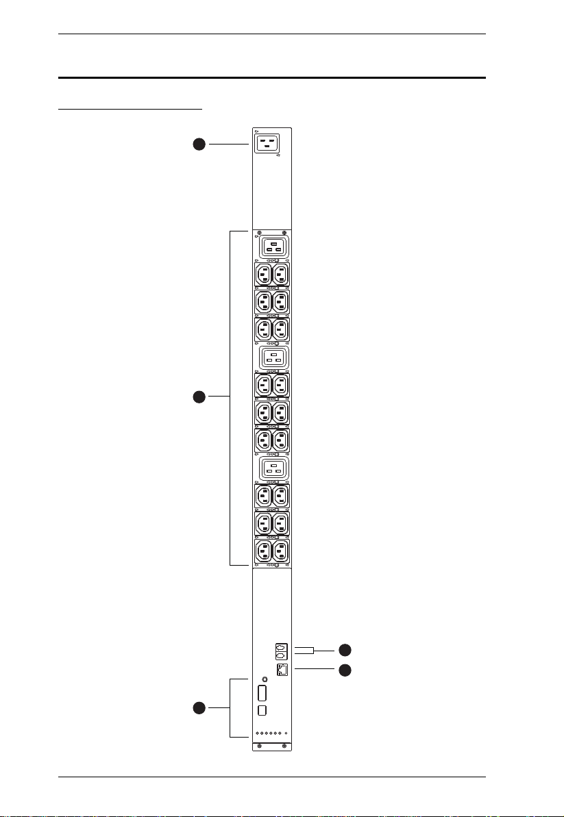
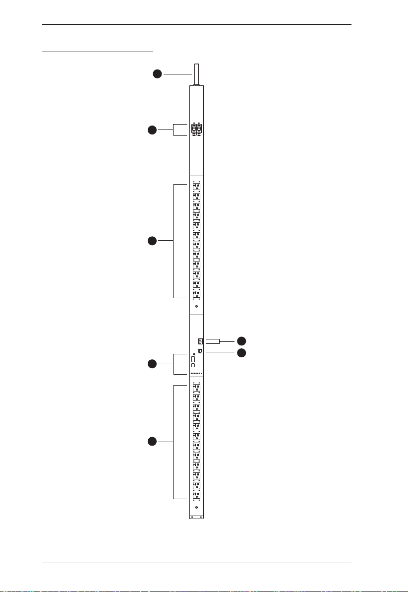
PE5324TA Front View
12

Chapter 1. Introduction
No. Item Description
1 Power Cord This is the power cord that connects the unit to an
2 Circuit Breakers (Bank 1
and Bank 2)
3 Power Outlets* 24 x NEMA 5-20R
4 Sensor Ports External sensors plug into these two RJ-11 ports.
5 LAN Port and LEDs The cable that connects the eco PDU to the LAN
6 Readout Section, LEDs
and Reset Switch
AC power source via NEMA L5-30P plug.
2 x 16A Slim Breakers. As a safety measure, if
there is an overcurrent situation regarding the
device’s power, the circuit breakers will trip. Push
the switch back to recover normal operation.
plugs in here. The Link and LAN LEDs are built
into the LAN port:
Link: Lights GREEN to indicate that a connection
via the eco PDU's RJ-45 Ethernet port has been
established. Flashes to indicate data is being
transmitted.
LAN: Lights ORANGE to indicate 10 Mbps data
transmission speed. The LED lights GREEN to
indicate 100 Mbps data transmission speed.
Details of this section are provided on page 18.
Note: Holes for ATEN Lok-U-Plug cable holders are located around the
outlets. See Securing the Cables / Plugs, page 23, for further
information.
13
PE5T User Manual
6
1
2
4
5
3
3
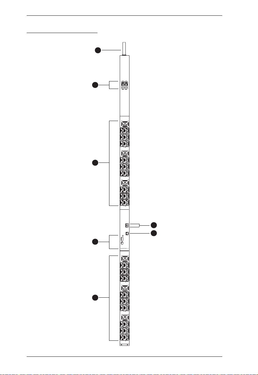
PE5342TB Front View
14

Chapter 1. Introduction
No. Item Description
1 Power Cord This is the power cord that connects the unit to an
2 Circuit Breakers (Bank 1
and Bank 2)
3 Power Outlets* 42 in total (36 x IEC320 C13 + 6 x IEC320 C19
4 Sensor Ports External sensors plug into these two RJ-11 ports.
5 LAN Port and LEDs The cable that connects the eco PDU to the LAN
6 Readout Section, LEDs
and Reset Switch
AC power source via NEMA L6-30P plug.
2 x 16A Slim Breakers. As a safety measure, if
there is an overcurrent situation regarding the
device’s power, the circuit breakers will trip. Push
the switch back to recover normal operation.
plugs in here. The Link and LAN LEDs are built
into the LAN port:
Link: Lights GREEN to indicate that a connection
via the eco PDU's RJ-45 Ethernet port has been
established. Flashes to indicate data is being
transmitted.
LAN: Lights ORANGE to indicate 10 Mbps data
transmission speed. The LED lights GREEN to
indicate 100 Mbps data transmission speed.
Details of this section are provided on page 18.
Note: Holes for ATEN Lok-U-Plug cable holders are located around the
sockets. See Securing the Cables / Plugs, page 23, for further
information.
15
PE5T User Manual
6
1
2
4
5
3
3
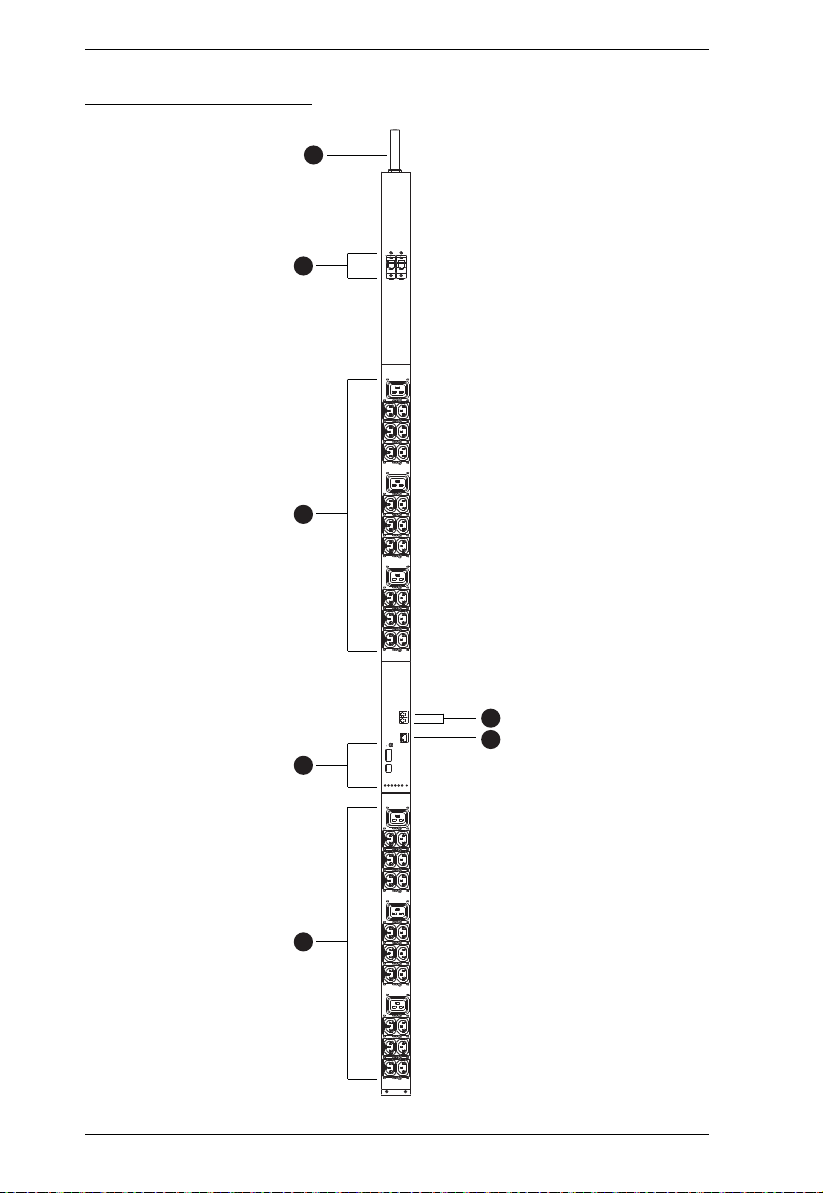
PE5342TG Front View
16
 Loading...