

IP Control Box
PE4104G User Manual
www.aten.com

PE4104G User Manual
EMC Information
FEDERAL COMMUNICATIONS COMMISSION INTERFERENCE
STATEMENT. This equipment has been tested and found to comply with the
limits for a Class A digital device, pursuant to Part 15 of the FCC Rules. These
limits are designed to provide reasonable protection against harmful
interference when the equipment is operated in a commercial environment.
This equipment generates, uses, and can radiate radio frequency energy and, if
not installed and used in accordance with the instruction manual, may cause
harmful interference to radio communications. Operation of this equipment in
a residential area is likely to cause harmful interference in which case the user
will be required to correct the interference at his own expense.
FCC Caution: Any changes or modifications not expressly approved by the
party responsible for compliance could void the user's authority to operate this
equipment.
This device complies with Part 15 of the Fcc Rules. Operation is subject to the
following two conditions:
(1) this device may not cause harmful interference, and
(2) this device must accept any interference received, including interference
that may cause undesired operation.
Warning: Operation of this equipment in a residential environment could
cause radio interference.
Achtung: Der Gebrauch dieses Geräts in Wohnumgebung kann
Funkstörungen verursachen.
KCC Statement
RoHS
This product is RoHS compliant.
© Copyright 2021 ATEN® International Co., Ltd.
ATEN and the ATEN logo are registered trademarks of ATEN International Co., Ltd. All rights reserved.
All other brand names and trademarks are the registered property of their respective owners.
ii
Released Date: 2021-01-14

PE4104G User Manual
User Information
Online Registration
Be sure to register your product at our online support center:
International http://support.aten.com
Telephone Support
For telephone support, call this number:
International 886-2-8692-6959
China 86-400-810-0-810
Japan 81-3-5615-5811
Korea 82-2-467-6789
North America 1-888-999-ATEN ext 4988
1-949-428-1111
User Notice
All information, documentation, and specifications contained in this ma nual are subject
to change without prior notification by the manufacturer. The manufacturer makes no
representations or warranties, either expressed or implied, with respect to the contents
hereof and specifically disclaims any warranties as to merchantability or fitness for any
particular purpose. Any of the manufacturer's software described in this manual is sold
or licensed as is. Should the programs prove defective following their purchase, the
buyer (and not the manufacturer, its distributor, or its dealer), assume s th e entire cost of
all necessary servicing, repair and any incidental or consequential damages resulting
from any defect in the software.
The manufacturer of this system is not responsible for any radio and/or TV interference
caused by unauthorized modifications to this device. It is the responsibility of the user
to correct such interference.
The manufacturer is not responsible for any damage incurred in the operation of this
system if the correct operational voltage setting was not selected prior to operation.
PLEASE VERIFY THAT THE VOLTAGE SETTING IS CORRECT BEFORE USE.
If any bodily injury or property damage with respect to operation of the product results
from users not having installed the product in accordance with the instructions provided
in the product’s user manual, or the product is used in an environment with a current
load over the designed specifications of the product, ATEN is not liable for any loss or
damage.
iii

PE4104G User Manual
Package Contents
1 PE4104G IP Control Box
1 Standard Rack Mount Kit
1 Power Cord
4Footpads
1 User Instructions*
Check to make sure that all of the components are present and in good order.
If anything is missing, or was damaged in shipping, contact your dealer.
Read this manual thoroughly and follow the installation and operation
procedures carefully to prevent any damage to the unit or to any other devices
connecting to the unit.
* Features may have been added to the unit since this manual was published.
Please visit our website to download the most up-to-date version.
iv

PE4104G User Manual
Contents
EMC Information . . . . . . . . . . . . . . . . . . . . . . . . . . . . . . . . . . . . . . . . . . . . ii
User Information . . . . . . . . . . . . . . . . . . . . . . . . . . . . . . . . . . . . . . . . . . . . .iii
Online Registration . . . . . . . . . . . . . . . . . . . . . . . . . . . . . . . . . . . . . . . .iii
Telephone Support . . . . . . . . . . . . . . . . . . . . . . . . . . . . . . . . . . . . . . . .iii
User Notice . . . . . . . . . . . . . . . . . . . . . . . . . . . . . . . . . . . . . . . . . . . . . .iii
Package Contents . . . . . . . . . . . . . . . . . . . . . . . . . . . . . . . . . . . . . . . . . . iv
About This Manual . . . . . . . . . . . . . . . . . . . . . . . . . . . . . . . . . . . . . . . . . .viii
Conventions . . . . . . . . . . . . . . . . . . . . . . . . . . . . . . . . . . . . . . . . . . . . ix
Product Information. . . . . . . . . . . . . . . . . . . . . . . . . . . . . . . . . . . . . . . . . . ix
Chapter 1.
Overview . . . . . . . . . . . . . . . . . . . . . . . . . . . . . . . . . . . . . . . . . . . . . . . . . . . 1
Features . . . . . . . . . . . . . . . . . . . . . . . . . . . . . . . . . . . . . . . . . . . . . . . . . . . 2
Requirements . . . . . . . . . . . . . . . . . . . . . . . . . . . . . . . . . . . . . . . . . . . . . . .3
Optional Accessories . . . . . . . . . . . . . . . . . . . . . . . . . . . . . . . . . . . . . . . . .4
Components . . . . . . . . . . . . . . . . . . . . . . . . . . . . . . . . . . . . . . . . . . . . . . . .5
Chapter 2.
Rack Mounting . . . . . . . . . . . . . . . . . . . . . . . . . . . . . . . . . . . . . . . . . . . . . . 7
Installation . . . . . . . . . . . . . . . . . . . . . . . . . . . . . . . . . . . . . . . . . . . . . . . . . 9
Chapter 3.
Introduction
Sensors . . . . . . . . . . . . . . . . . . . . . . . . . . . . . . . . . . . . . . . . . . . . . . . . 4
Sensor Management . . . . . . . . . . . . . . . . . . . . . . . . . . . . . . . . . . .4
Cable Holders . . . . . . . . . . . . . . . . . . . . . . . . . . . . . . . . . . . . . . . . . . . .4
PE4104G Front View. . . . . . . . . . . . . . . . . . . . . . . . . . . . . . . . . . . . . . .5
PE4104G Rear View . . . . . . . . . . . . . . . . . . . . . . . . . . . . . . . . . . . . . .6
Hardware Setup
Desktop Mount . . . . . . . . . . . . . . . . . . . . . . . . . . . . . . . . . . . . . . . . . . .7
Using the Rack Mount Ears. . . . . . . . . . . . . . . . . . . . . . . . . . . . . . . . . .7
Securing the Cable . . . . . . . . . . . . . . . . . . . . . . . . . . . . . . . . . . . . . . .10
Basic Operation and
First Time Setup
Operation Methods . . . . . . . . . . . . . . . . . . . . . . . . . . . . . . . . . . . . . . . . . .11
Browser . . . . . . . . . . . . . . . . . . . . . . . . . . . . . . . . . . . . . . . . . . . . . . . 11
eco DC . . . . . . . . . . . . . . . . . . . . . . . . . . . . . . . . . . . . . . . . . . . . . . . .11
SNMP . . . . . . . . . . . . . . . . . . . . . . . . . . . . . . . . . . . . . . . . . . . . . . . . .11
First Time Setup . . . . . . . . . . . . . . . . . . . . . . . . . . . . . . . . . . . . . . . . . . . .12
Network Configuration . . . . . . . . . . . . . . . . . . . . . . . . . . . . . . . . . . . .13
Changing the Administrator Login . . . . . . . . . . . . . . . . . . . . . . . . . . . . 13
Moving On. . . . . . . . . . . . . . . . . . . . . . . . . . . . . . . . . . . . . . . . . . . . . . . . .14
Chapter 4.
Logging In . . . . . . . . . . . . . . . . . . . . . . . . . . . . . . . . . . . . . . . . . . . . . . . . .15
The eco PDU Main Page . . . . . . . . . . . . . . . . . . . . . . . . . . . . . . . . . . . . .17
Energy . . . . . . . . . . . . . . . . . . . . . . . . . . . . . . . . . . . . . . . . . . . . . . . . . . .19
Browser Operation
Page Components. . . . . . . . . . . . . . . . . . . . . . . . . . . . . . . . . . . . . . . .17
v

PE4104G User Manual
Connections . . . . . . . . . . . . . . . . . . . . . . . . . . . . . . . . . . . . . . . . . . . . 19
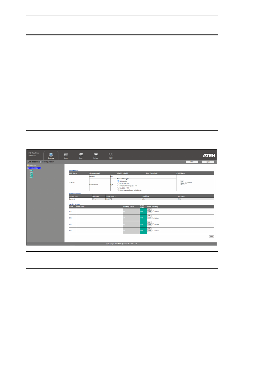
PDU Status . . . . . . . . . . . . . . . . . . . . . . . . . . . . . . . . . . . . . . . . . . 19
Sensor Status . . . . . . . . . . . . . . . . . . . . . . . . . . . . . . . . . . . . . . . . 20
Outlet Status . . . . . . . . . . . . . . . . . . . . . . . . . . . . . . . . . . . . . . . . . 20
Configuration . . . . . . . . . . . . . . . . . . . . . . . . . . . . . . . . . . . . . . . . . . . 21
Power On Time Schedule Settings . . . . . . . . . . . . . . . . . . . . . . . . 21
Buzzer Setting . . . . . . . . . . . . . . . . . . . . . . . . . . . . . . . . . . . . . . . . 21
Outlet Configuration . . . . . . . . . . . . . . . . . . . . . . . . . . . . . . . . . . . 21
User . . . . . . . . . . . . . . . . . . . . . . . . . . . . . . . . . . . . . . . . . . . . . . . . . . . . . 25
Administrator Information . . . . . . . . . . . . . . . . . . . . . . . . . . . . . . . . . . 25
SNMPv3 Account Information . . . . . . . . . . . . . . . . . . . . . . . . . . . . 25
SNMPv1/v2c Community . . . . . . . . . . . . . . . . . . . . . . . . . . . . . . . 26
Telnet . . . . . . . . . . . . . . . . . . . . . . . . . . . . . . . . . . . . . . . . . . . . . . 26
SSH . . . . . . . . . . . . . . . . . . . . . . . . . . . . . . . . . . . . . . . . . . . . . . . . 26
User Information . . . . . . . . . . . . . . . . . . . . . . . . . . . . . . . . . . . . . . . . . 26
Log . . . . . . . . . . . . . . . . . . . . . . . . . . . . . . . . . . . . . . . . . . . . . . . . . . . . . . 28
System Log . . . . . . . . . . . . . . . . . . . . . . . . . . . . . . . . . . . . . . . . . . . . . 28
Notification Settings . . . . . . . . . . . . . . . . . . . . . . . . . . . . . . . . . . . . . . 29
Setup . . . . . . . . . . . . . . . . . . . . . . . . . . . . . . . . . . . . . . . . . . . . . . . . . . . . 31
Device Configuration. . . . . . . . . . . . . . . . . . . . . . . . . . . . . . . . . . . . . . 31
General . . . . . . . . . . . . . . . . . . . . . . . . . . . . . . . . . . . . . . . . . . . . . 31
Service Ports . . . . . . . . . . . . . . . . . . . . . . . . . . . . . . . . . . . . . . . . 32
IPv4 Configuration . . . . . . . . . . . . . . . . . . . . . . . . . . . . . . . . . . . . 33
Event Notification . . . . . . . . . . . . . . . . . . . . . . . . . . . . . . . . . . . . . 34
Date/Time . . . . . . . . . . . . . . . . . . . . . . . . . . . . . . . . . . . . . . . . . . . 37
Finishing Up . . . . . . . . . . . . . . . . . . . . . . . . . . . . . . . . . . . . . . . . . 38
Security . . . . . . . . . . . . . . . . . . . . . . . . . . . . . . . . . . . . . . . . . . . . . . . 39
Working Mode . . . . . . . . . . . . . . . . . . . . . . . . . . . . . . . . . . . . . . . 40
TLS Support . . . . . . . . . . . . . . . . . . . . . . . . . . . . . . . . . . . . . . . . . 40
IPInstaller Setting . . . . . . . . . . . . . . . . . . . . . . . . . . . . . . . . . . . . . 40
Session Timeout . . . . . . . . . . . . . . . . . . . . . . . . . . . . . . . . . . . . . . 40
Account Policy. . . . . . . . . . . . . . . . . . . . . . . . . . . . . . . . . . . . . . . . 40
IP Filter / Mac Filter . . . . . . . . . . . . . . . . . . . . . . . . . . . . . . . . . . . . 41
Authentication & Authorization . . . . . . . . . . . . . . . . . . . . . . . . . . . 44
Private Certificate . . . . . . . . . . . . . . . . . . . . . . . . . . . . . . . . . . . . . 45
EcoTCP. . . . . . . . . . . . . . . . . . . . . . . . . . . . . . . . . . . . . . . . . . . . . . . . 46
PDU . . . . . . . . . . . . . . . . . . . . . . . . . . . . . . . . . . . . . . . . . . . . . . . . . . . . . 47
Upgrade Main Firmware . . . . . . . . . . . . . . . . . . . . . . . . . . . . . . . . . . . 47
Firmware File. . . . . . . . . . . . . . . . . . . . . . . . . . . . . . . . . . . . . . . . . 47
Backup/Restore . . . . . . . . . . . . . . . . . . . . . . . . . . . . . . . . . . . . . . . . . 49
Station List. . . . . . . . . . . . . . . . . . . . . . . . . . . . . . . . . . . . . . . . . . . 49
Backup . . . . . . . . . . . . . . . . . . . . . . . . . . . . . . . . . . . . . . . . . . . . . 49
Restore . . . . . . . . . . . . . . . . . . . . . . . . . . . . . . . . . . . . . . . . . . . . . 50
Chapter 5.
Remote Terminal Operations . . . . . . . . . . . . . . . . . . . . . . . . . . . . . . . . . . 51
vi
Telnet Commands

PE4104G User Manual
Telnet . . . . . . . . . . . . . . . . . . . . . . . . . . . . . . . . . . . . . . . . . . . . . . . . .51
Setup . . . . . . . . . . . . . . . . . . . . . . . . . . . . . . . . . . . . . . . . . . . . . .51
Logging In . . . . . . . . . . . . . . . . . . . . . . . . . . . . . . . . . . . . . . . . . . .51
Session Timeout . . . . . . . . . . . . . . . . . . . . . . . . . . . . . . . . . . . . . . . . .52
Commands . . . . . . . . . . . . . . . . . . . . . . . . . . . . . . . . . . . . . . . . . . . . . . . .53
Verification . . . . . . . . . . . . . . . . . . . . . . . . . . . . . . . . . . . . . . . . . . . . .53
Read Power Outlet Status . . . . . . . . . . . . . . . . . . . . . . . . . . . . . . . . .54
Switch Outlet Status . . . . . . . . . . . . . . . . . . . . . . . . . . . . . . . . . . . . . . 55
Read Environmental Value . . . . . . . . . . . . . . . . . . . . . . . . . . . . . . . . .57
Close Telnet Session . . . . . . . . . . . . . . . . . . . . . . . . . . . . . . . . . . . . .58
Reboot PDU Device . . . . . . . . . . . . . . . . . . . . . . . . . . . . . . . . . . . . . . 59
Reset All PDU Config to Default Value . . . . . . . . . . . . . . . . . . . . . . . . 59
Appendix
Safety Instructions. . . . . . . . . . . . . . . . . . . . . . . . . . . . . . . . . . . . . . . . . . .61
General . . . . . . . . . . . . . . . . . . . . . . . . . . . . . . . . . . . . . . . . . . . . . . . .61
Rack Mounting . . . . . . . . . . . . . . . . . . . . . . . . . . . . . . . . . . . . . . . . . .63
Technical Support . . . . . . . . . . . . . . . . . . . . . . . . . . . . . . . . . . . . . . . . . . 64
International . . . . . . . . . . . . . . . . . . . . . . . . . . . . . . . . . . . . . . . . . . . .64
North America . . . . . . . . . . . . . . . . . . . . . . . . . . . . . . . . . . . . . . . . . .64
IP Address Determination . . . . . . . . . . . . . . . . . . . . . . . . . . . . . . . . . . . .65
Method 1: . . . . . . . . . . . . . . . . . . . . . . . . . . . . . . . . . . . . . . . . . . . 65
Method 2:. . . . . . . . . . . . . . . . . . . . . . . . . . . . . . . . . . . . . . . . . . . . 66
Method 3:. . . . . . . . . . . . . . . . . . . . . . . . . . . . . . . . . . . . . . . . . . . . 66
Specifications . . . . . . . . . . . . . . . . . . . . . . . . . . . . . . . . . . . . . . . . . . . . . . 67
PE4104G. . . . . . . . . . . . . . . . . . . . . . . . . . . . . . . . . . . . . . . . . . . . . . . 67
Administrator Login Failure . . . . . . . . . . . . . . . . . . . . . . . . . . . . . . . . . . . 69
Limited Warranty . . . . . . . . . . . . . . . . . . . . . . . . . . . . . . . . . . . . . . . . . . .70
vii

PE4104G User Manual
About This Manual
This User Manual is provided to help you get the most from the PE4104G unit/
system. It covers all aspects of installation, configuration and operation. An
overview of the information in the manual is provided below.
Chapter 1, Introduction, introduces you to the unit/system. It presents
purpose, features and benefits are presented, and its front and back panel
components are described.
Chapter 2, Hardware Setup, provides step-by-step instructions for setting
up your installation, and explains some basic operation procedures.
Chapter 3, Basic Operation and First Time Setup, explains the
procedures that the Administrator employs to set up the PE4104G network
environment, and change the default username and password.
Chapter 4, Browser Operation, describes how to log in to the PE4104G
with an Internet browser, and explains the layout and components of the
PE4104G’s user interface.
Chapter 5, Telnet Commands, describes how to connect to and access the
PE4104G’s using Telnet.
An Appendix, at the end of the manual provides technical and
troubleshooting information.
viii

Conventions
This manual uses the following conventions:
Monospaced Indicates text that you should key in.
[ ] Indicates keys you should press. For example, [Enter] means
to press the Enter key. If keys need to be chorded, they appear
together in the same bracket with a plus sign between them:
[Ctrl+Alt].
1. Numbered lists represent procedures with sequential steps.
♦ Bullet lists provide information, but do not involve sequential
steps.
→ Indicates selecting the option (on a menu or dialog box, for
example), that comes next. For example, Start
to open the Start menu, and then select Run.
Indicates critical information.
Product Information
PE4104G User Manual
→
Run means
For information about all ATEN products and how they can help you connect
without limits, visit ATEN on the Web or contact an ATEN Authorized
Reseller. Visit ATEN on the Web for a list of locations and telephone numbers:
International http://www.aten.com
North America http://www.aten-usa.com
ix

PE4104G User Manual
This Page Intentionally Left Blank
x

Chapter 1
Introduction
Overview
Engineered to be an intelligent power distribution solution, the PE4104G IP
Control Box ships with 4 power outlets in an IEC socket configuration. It
provides secure, centralized, intelligent, and remote power management of
data center IT equipment to minimize the operating cost.
The PE4104G features remote power control function, allowing you to control
devices attached to the PDU at the PDU device level from practically any
location via a TCP/IP connection. The power sequence design eliminates the
risks for a power inrush to guarantee reliable operation and protects the overall
system health. With the support for eco DC software, it provides an easy
method for managing multiple devices, offering an intuitive and user-friendly
Graphical User Interface that allows you to configure a PDU device and reboot
the device in case any equipment lock-up occurs. The administrators can
switch on/off or set a delay time for each power outlet or individual power
outlets group whenever, wherever.
The PE4104G boasts a slim, compact form factor and supports desk mount as
well as rack mount, ensuring easy installation in confined spaces. It is a smart
power control box tailored for hospitality or retail applications, such as digital
signages and video walls, for edge computing devices, including routers,
servers and cameras, or for any data center environments where there is no
need to keep the servers powered on at all times.
1

PE4104G User Manual
Features
Power Distribution
Space saving slim form factor
IEC power outlet
Separates power for the unit’s own power and its power outlets – user
interface is still accessible even when an overload condition trips the
device’s circuit breaker
Remote Access
Remote power control via TCP/IP and a built in 10/100 Ethernet port
Network Interfaces: TCP/IP, UDP, HTTP, HTTPS, SSL, SMTP, ARP,
NTP, DNS, SNMP V1&V2&V3, auto sense, Ping, Telnet, Modbus (Over
TCP IP)
Works with web-based eco DC software
Operation
Local and Remote power outlet control (On, Off, Power Cycle) by
individual outlets
Power-on sequencing – users can set the power on sequence and delay
time for each port to allow equipment to be turned on in a proper order
Easy setup and operation via a browser-based user interface
Security
Two-level password security
Strong security features include password protection and advanced
encryption technologies – TLS1.2
Remote authentication support: RADIUS
2

Chapter 1. Introduction
Requirements
Browsers accessing the PE4104G unit must support 2048 and 4096 bit
encryption.
For cold booting of attached computers, the computer’s BIOS must
support wake on LAN or System after AC Back.
For Safe Shutdown:
The computer must be running Windows (Windows 2000 or higher) or
Linux.
The Safe Shutdown program (available by download from our
website), must be installed and running on the computer.
3

PE4104G User Manual
Optional Accessories
Sensors
Sensors are optional accessories. You can use the PE4104G unit without
sensors. However, if you want to have complete energy management of an
instrumented data center with the use of the PE4104G, you would need to use
eco DC software and install sensor to generate a complete energy-efficient data
and chart. Higher sensor installation density is helpful to generate more
accurate data. A sensor-enabled installation is required to generate a more
complete energy-efficient data and chart. Higher sensor installation density is
helpful to generate more accurate data. Available sensors are show in the table,
below:
Sensor Part Number
Temperature EA1140
Temperature / Humidity EA1240
Differential Pressure / Temperature EA1340
Sensor Management
Sensors can be managed via the PE4104G’s built-in graphical user interface
(GUI) or with the eco DC software that can be downloaded from the ATEN
website.
Cable Holders
Cable holders are optional accessories. For added safety, use ATEN Lok-UPlug cable holders to secure the cables from your attached devices in place on
the eco PDU unit. Use only the ATEN Lok-U-Plug cable holders that have
been specifically designed to work with the eco PDU. Using any other kind of
cable securing device could be highly dangerous. For more information, see
Securing the Cable, page 10.
Part Number Description
2X-EA07 Lok-U-Plug Cable Holder (10 pcs)
2X-EA08 Lok-U-Plug Installation Tool (4 pcs)
2X-EA10 C14 EZ-Lok Plug Connector (10 pcs)
2X-EA13 C14 Smart-Lok Plug Connector (10 pcs)
4
Chapter 1. Introduction
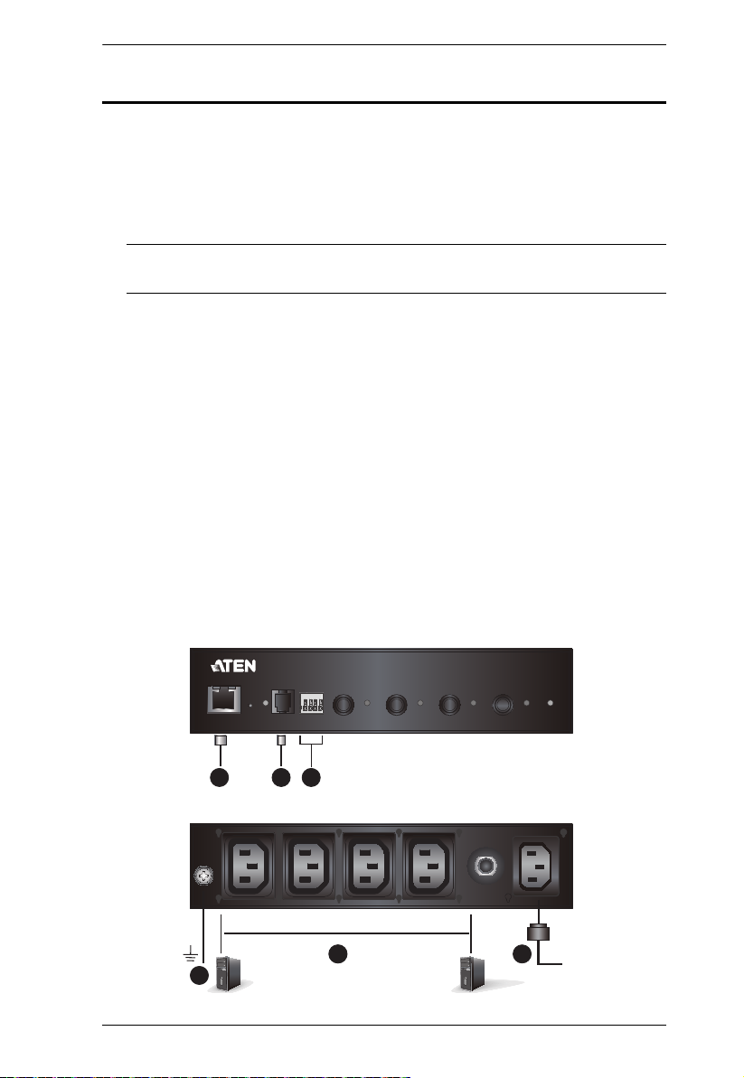
1 2 543 6
Components
PE4104G Front View
No. Component Description
1 LAN Port The Cat 5e cable that connects the unit to the Internet
2 Reset Button
(recessed)
3 Sensor Port & LED The external sensor plug into this RJ-11 port, and the
4 Door Sensor Dry-
Contact Port
5 Power Control Buttons
& LED
6 Device Power LED The Device Power LED lights orange to indicate the unit
plugs in here.
Press and release to reboot the unit. This Reset Button
is recessed and must be pushed with a thin object, such
as the end of a paper clip, or a ballpoint pen.
sensor LED lights orange when a sensor is connected to
the sensor port.
The external door sensor plug into this Door Sensor DryContact port.
Each Power Control Button (1 to 4), controls the power
status of its corresponding AC output port as follow:
Pressing and holding the button in for more than 3
seconds switches the power to its corresponding
port on of off.
The LEDs light green to indicate that there is electricity
going to its corresponding outlet.
is powered up and ready to operate.
5

PE4104G User Manual
21 3 4
PE4104G Rear View
No. Component Description
1 Grounding Terminal Connects to a suitable grounding object.
2 Power Outlet Sockets Electrical appliances plug in here.
3 Circuit Breaker Protects the PDU from damage caused by excess
current from an overload or short circuit.
4 Power Inlet Socket The power cord of the package content plugs in here.
6
Chapter 2
Important safety information regarding the placement of this device is
provided on page 61. Please review it before proceeding.
12
34
Unit
Front
Rear
Rack Mount Ears Rack Mount Ears
Rack Mount Ears Rack Mount Ears
Hardware Setup
Rack Mounting
The PE4104G can be mounted vertically on the outside of the rack and a few
options are available.
Desktop Mount
If you wish to keep your unit on a desktop, attach the footpads (in the package
content) and place the unit on any appropriate level surface that can safely
support its weight plug the weight of its attached cables.
Using the Rack Mount Ears
1. Decide where you would rack mount the unit and choose the place you
would attach the rack mount ear (Position 1, 2, 3, or 4). As an example, we
will choose to attach the mounting ears shown below (position 3).
7
PE4104G User Manual
2. Align and stabilize the mounting ear using M3 Phillips Hex Screws.
3. Align the unit and the mounting ear to the rack and stabilize the unit using
rack screws. Let the buttons stabilize in the button holes and the mounting
is complete.
8
Chapter 2. Hardware Setup
1
6
Rear
2
3 4
Front
5
Installation
To set up your PE4104G installation, refer to the numbered steps in the
installation diagram below (the numbers in the diagram correspond to the
numbered steps), and do the following:
1. Ground the PE4104G by connecting one end of a grounding wire to the
Grounding Terminal and the other end to a suitable grounded object.
Note: Do not omit this step. Proper grounding helps to prevent damage to
the unit from power surges or static electricity.
2. For each device you want to connect, connect its power cable to any
available outlet on the unit. Optionally, use ATEN Lok-U-Plug cable
holders to secure them. See Securing the Cable, page 10.
3. Connect an internet-enabled LAN cable into the unit’s LAN Port.
4. (Optional) If you are to use an environmental sensor in your installation,
connect it to the RJ-11 Sensor Port located on the unit’s front panel.
5. (Optional) If you are to use a door sensor in your installation, connect it to
the Door Sensor Dry-Contact Port located on the unit’s front panel.
6. Use the provided Power Cord to connect the unit’s Power Inlet Socket to
an AC power source.
7. Once you have finished these installation steps, you can turn on the
connected devices.
9
PE4104G User Manual
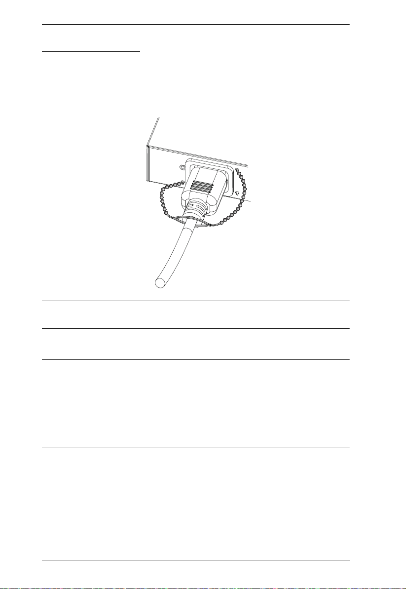
Securing the Cable
For added safety, use ATEN Lok-U-Plug cable holders to secure the cables
from your attached devices in place on the unit. Secure the cable holders using
the specially designed holes around the individual power outlets, as shown
below:
Note: Lok-U-Plug Cable Holders and their Installation Tools are optional and
sold separately. See Cable Holders, page 4
Note:
Lok-U-Plug Cable Holders and their Installation Tools are optional and
sold separately. See Cable Holders, page 4.
Use only the ATEN Lok-U-Plug cable holders that have been specifically
designed to work with the eco PDU. Using any other kind of cable
securing device could be highly dangerous.
10

Chapter 3
Basic Operation and
First Time Setup
Operation Methods
The PE4104G provide three methods to access and manage your installation:
Browser, eco DC Energy Management Software and SNMP.
Note: The following sections of this chapter contain information concerning
Browser operation. For eco DC operation, please refer to the separate
eco DC User Manual. The eco DC software and User Manual can be
downloaded from the ATEN website.
Browser
The PE4104G can be accessed and controlled via any supported Internet
browser from any platform. See First Time Setup, page 12, and the following
sections in this chapter, for full details.
eco DC
The eco DC Energy Management Software. eco DC provides you with an easy
method for managing multiple devices, offering an intuitive and user-friendly
Graphical Interface that allows you to configure a PDU device and monitor
power status of the equipment connected to it. eco DC Energy Management
Software can be downloaded from the ATEN website, along with a separate
eco DC User Manual.
SNMP
The eco PDU supports any 3rd party V3 SNMP Manager Software. SNMP
Management Information Database (MIB) files for the eco PDU device can be
found on the software.
11
PE4104G User Manual
First Time Setup
Once the eco PDU installation has been cabled up, the next task the
Administrator needs to perform involve configuring the network parameters,
changing the default Super Administrator login settings, and adding users.
The way to accomplish this is to log in via web browser.
Note: 1. Since this is the first time you are logging in, use the default
Username: administrator; and the default Password: password. For
security purposes we recommend changing them to something unique
(see Changing the Administrator Login, page 13).
2. For remote methods of getting logged in to the PDU, see IP Address
Determination, page 65.
After you successfully log in, the eco PDU Energy/Connections page appears:
Note: Operation details are discussed in Energy, page 19, in the next chapter.
For further setup information, continue with this chapter
12
Chapter 3. Basic Operation and First Time Setup
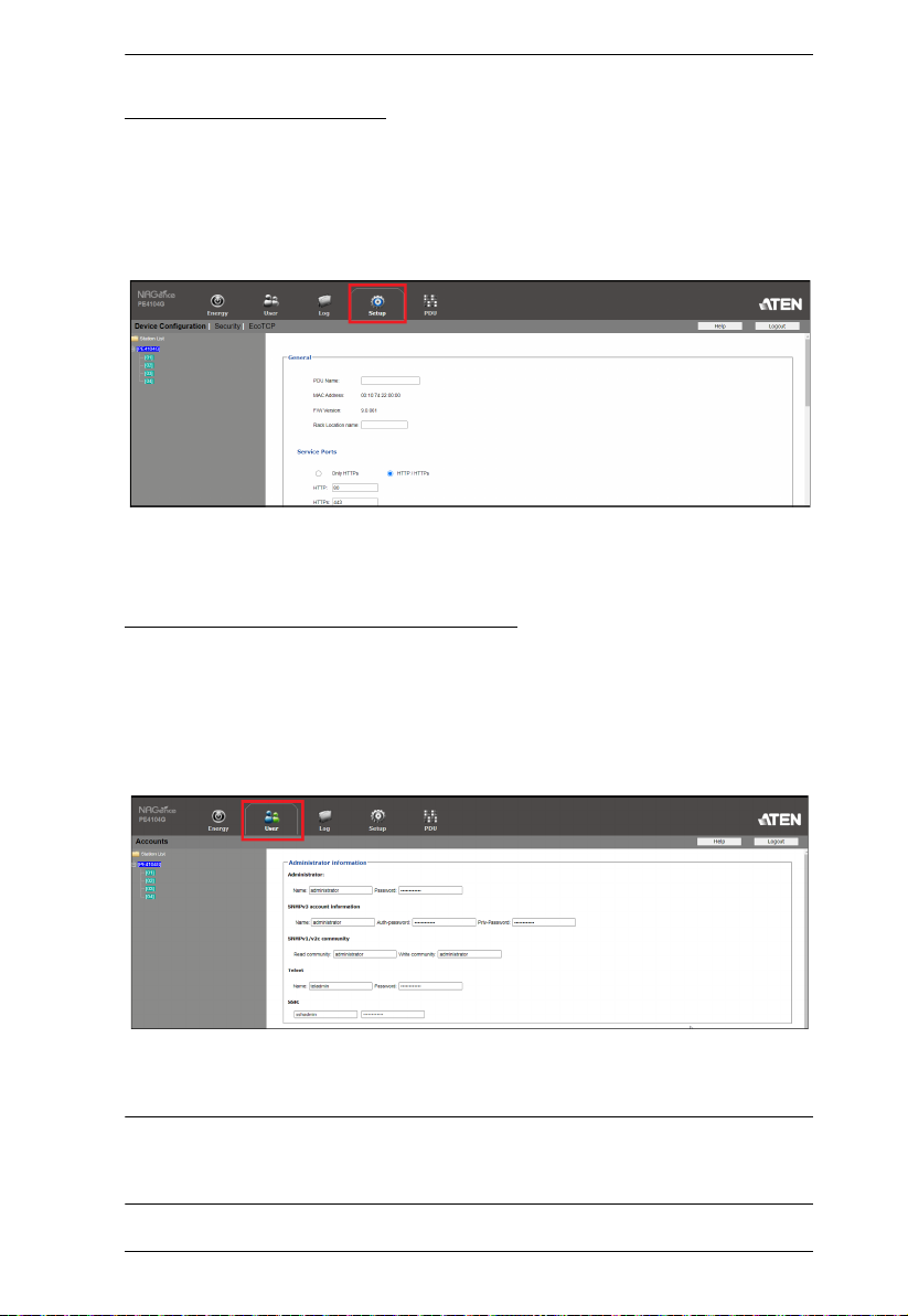
Network Configuration
To configure the network settings, do the following:
1. Click the Setup tab.
2. The interface displays the Device Configuration page. A screen similar to
the one below appears:
3. Fill in the fields according to the information provided under Device
Configuration, page 31.
Changing the Administrator Login
To change the default Administrator username and password, do the following:
1. Click the User tab.
The Accounts page has a detailed list of users – with more information
about them – in the large central panel:
2. In the Administrator Information section, reset the name and password
fields to something unique, then click Save (at the bottom of the page.)
Note: If you forget the Administrator’s name or password, short the
mainboard jumper to restore the default Administrator account. See
Administrator Login Failure, page 69 in the Appendix for full details.
13

PE4104G User Manual
Moving On
After setting up the network and changing the default Administrator username
and password, you can proceed to other administration activities – including
adding users. This is covered in the next chapter.
14
 Loading...