

ATEN KN1000A User Manual
Single Port KVM over IP Switch with Single Port Power Switch
KN1000A
User Manual
www.aten.com

KN1000A User Manual
EMC Information
FEDERAL COMMUNICATIONS COMMISSION INTERFERENCE STATEMENT:
This equipment has been tested and found to comply with the limits for a Class A digital device, pursuant to Part 15 of the FCC Rules. These limits are designed to provide
reasonable protection against harmful interference when the equipment is operated in a
commercial environment. This equipment generates, uses, and can radiate radio frequency energy and, if not installed and used in accordance with the instruction manual,
may cause harmful interference to radio communications. Operation of this equipment
in a residential area is likely to cause harmful interference in which case the user will
be required to correct the interfer ence at his own expense.
The device complies with Part 15 of the FCC Rules. Operation is subject to the follo wing two conditions: (1) this device may not cause harmful interference, and (2) this
device must accept any interference received, including interf ere n ce that may cause
undesired operation.
FCC Caution: Any changes or modifications not expressly approved by the party
responsible for compliance could void the user's authority to operate this equipment.
Warning: This equipment is compliant with Class A of CISPR 32. In a residential
environment this equipment may cause radio interference.
Warning: Operation of this equipment in a residential environment could cause radio
interference.
Suggestion: Shielded twisted pair (STP) cables must be used with the unit to ensure
compliance with FCC & CE standards.
KCC Statement
유선 제품용 / A 급 기기 ( 업무용 방송 통신 기기 )
이 기기는 업무용 (A 급 ) 전자파적합기기로서 판매자 또는 사용자는 이
점을 주의하시기 바라며 , 가정 외의 지역에서 사용하는 것을 목적으로
합니다 .
ii

RoHS
This product is RoHS compliant.
KN1000A User Manual
iii

KN1000A User Manual
User Information
Online Registration
Be sure to register your product at our online support center:
International http://eservice.aten.com
Telephone Support
For telephone support, call this number:
International 886-2-8692-6959
China 86-400-810-0-810
Japan 81-3-5615-5811
Korea 82-2-467-6789
North America 1-888-999-ATEN ext 4988
United Kingdom 44-8-4481-58923
User Notice
All information, documentation, and specifications contained in this m anual
are subject to change without prior notification by the manufacturer. The
manufacturer makes no representations or warranties, either expressed or
implied, with respect to the contents hereof and specifically disclaims any
warranties as to merchantability or fitness for any particular purpose. Any of
the manufacturer's software described in this manual is sold or licensed as is.
Should the programs prove defective following their purchase, the buyer (and
not the manufacturer, its distributor, or its dealer), assumes the entire cost of all
necessary servicing, repair and any incidental or consequential damages
resulting from any defect in the software.
The manufacturer of this system is not responsible for any radio and/or TV
interference caused by unauthorized modifications to this device. It is the
responsibility of the user to correct such interference.
The manufacturer is not responsible for any damage incurred in the operation
of this system if the correct operational voltage setting was not selected prior
to operation. PLEASE VERIFY THAT TH E VOLTAGE SETTING IS
CORRECT BEFORE USE.
iv

KN1000A User Manual
Copyright © 2017 ATEN® International Co., Ltd.
Manual Date: 2017-03-08
Altusen and the Altusen logo are registered trademarks of ATEN International Co., Ltd. All rights re-
served. All other brand names and trademarks are the registered property of their respective owners.
Package Contents
The basic KN1000A package consists of:
1 KN1000A
1 Custom KVM Cable Sets
1 Custom Console Cable Set
1 Mini USB to Type A USB Cable
1 Power Adapter
1 Outlet Power Cord
1 Mounting Kit
1 User Instructions*
Check to make sure that all of the components are present and in good order.
If anything is missing, or was damaged in shipping, contact your dealer.
Read this manual thoroughly and follow the installation and operation
procedures carefully to prevent any damage to the switch or to any other
devices on the KN1000A installation.
* Features may have been added to the KN1000A since this manual was
published. Please visit our website to download the most up-to-date version.
v

KN1000A User Manual
Contents
EMC Information . . . . . . . . . . . . . . . . . . . . . . . . . . . . . . . . . . . . . . . . . . . . . ii
User Information. . . . . . . . . . . . . . . . . . . . . . . . . . . . . . . . . . . . . . . . . . . . .iv
Online Registration . . . . . . . . . . . . . . . . . . . . . . . . . . . . . . . . . . . . . . . .iv
Telephone Support . . . . . . . . . . . . . . . . . . . . . . . . . . . . . . . . . . . . . . . .iv
User Notice . . . . . . . . . . . . . . . . . . . . . . . . . . . . . . . . . . . . . . . . . . . . . .iv
Package Contents . . . . . . . . . . . . . . . . . . . . . . . . . . . . . . . . . . . . . . . . . . . v
About This Manual . . . . . . . . . . . . . . . . . . . . . . . . . . . . . . . . . . . . . . . . . . .xi
Conventions . . . . . . . . . . . . . . . . . . . . . . . . . . . . . . . . . . . . . . . . . . . . xii
Product Information . . . . . . . . . . . . . . . . . . . . . . . . . . . . . . . . . . . . . . . . . xii
Terminology . . . . . . . . . . . . . . . . . . . . . . . . . . . . . . . . . . . . . . . . . . . .xiii
Chapter 1.
Introduction
Overview. . . . . . . . . . . . . . . . . . . . . . . . . . . . . . . . . . . . . . . . . . . . . . . . . . .1
Features and Benefits. . . . . . . . . . . . . . . . . . . . . . . . . . . . . . . . . . . . . . . . .3
System Requirements . . . . . . . . . . . . . . . . . . . . . . . . . . . . . . . . . . . . . . . . 7
Remote User Computers . . . . . . . . . . . . . . . . . . . . . . . . . . . . . . . . . . .7
Servers . . . . . . . . . . . . . . . . . . . . . . . . . . . . . . . . . . . . . . . . . . . . . . . . .7
Cables. . . . . . . . . . . . . . . . . . . . . . . . . . . . . . . . . . . . . . . . . . . . . . . . . .8
Video. . . . . . . . . . . . . . . . . . . . . . . . . . . . . . . . . . . . . . . . . . . . . . . . . . . 9
Operating Systems . . . . . . . . . . . . . . . . . . . . . . . . . . . . . . . . . . . . . . . .9
Browsers. . . . . . . . . . . . . . . . . . . . . . . . . . . . . . . . . . . . . . . . . . . . . . . 10
Components . . . . . . . . . . . . . . . . . . . . . . . . . . . . . . . . . . . . . . . . . . . . . . .11
Front View. . . . . . . . . . . . . . . . . . . . . . . . . . . . . . . . . . . . . . . . . . . . . . 11
Rear View . . . . . . . . . . . . . . . . . . . . . . . . . . . . . . . . . . . . . . . . . . . . . . 12
Custom Console Cable. . . . . . . . . . . . . . . . . . . . . . . . . . . . . . . . . . . .13
Chapter 2.
Hardware Setup
Mounting. . . . . . . . . . . . . . . . . . . . . . . . . . . . . . . . . . . . . . . . . . . . . . . . . .15
Rack Mounting . . . . . . . . . . . . . . . . . . . . . . . . . . . . . . . . . . . . . . . . . . 15
DIN Rail Mounting. . . . . . . . . . . . . . . . . . . . . . . . . . . . . . . . . . . . . . . .17
Installation. . . . . . . . . . . . . . . . . . . . . . . . . . . . . . . . . . . . . . . . . . . . . . . . . 18
Chapter 3.
Browser Login
Introduction. . . . . . . . . . . . . . . . . . . . . . . . . . . . . . . . . . . . . . . . . . . . . . . .21
Logging In. . . . . . . . . . . . . . . . . . . . . . . . . . . . . . . . . . . . . . . . . . . . . . . . .21
Chapter 4.
Configuration
Introduction. . . . . . . . . . . . . . . . . . . . . . . . . . . . . . . . . . . . . . . . . . . . . . . .23
Basic Setting. . . . . . . . . . . . . . . . . . . . . . . . . . . . . . . . . . . . . . . . . . . . . . .24
User Management. . . . . . . . . . . . . . . . . . . . . . . . . . . . . . . . . . . . . . . .24
Role. . . . . . . . . . . . . . . . . . . . . . . . . . . . . . . . . . . . . . . . . . . . . . . .24
vi

KN1000A User Manual
Permissions. . . . . . . . . . . . . . . . . . . . . . . . . . . . . . . . . . . . . . . . . .25
Sessions . . . . . . . . . . . . . . . . . . . . . . . . . . . . . . . . . . . . . . . . . . . . . . .26
Maintenance . . . . . . . . . . . . . . . . . . . . . . . . . . . . . . . . . . . . . . . . . . . .27
Upgrade Main Firmware . . . . . . . . . . . . . . . . . . . . . . . . . . . . . . . .27
Backup / Restore. . . . . . . . . . . . . . . . . . . . . . . . . . . . . . . . . . . . . .28
Advanced Setting . . . . . . . . . . . . . . . . . . . . . . . . . . . . . . . . . . . . . . . . . . .31
Device Information . . . . . . . . . . . . . . . . . . . . . . . . . . . . . . . . . . . . . . .31
General . . . . . . . . . . . . . . . . . . . . . . . . . . . . . . . . . . . . . . . . . . . . .31
Network. . . . . . . . . . . . . . . . . . . . . . . . . . . . . . . . . . . . . . . . . . . . . . . .32
IP Installer . . . . . . . . . . . . . . . . . . . . . . . . . . . . . . . . . . . . . . . . . . .33
Service Ports . . . . . . . . . . . . . . . . . . . . . . . . . . . . . . . . . . . . . . . . .33
Network Transfer Rate. . . . . . . . . . . . . . . . . . . . . . . . . . . . . . . . . .35
DDNS. . . . . . . . . . . . . . . . . . . . . . . . . . . . . . . . . . . . . . . . . . . . . . .35
ANMS . . . . . . . . . . . . . . . . . . . . . . . . . . . . . . . . . . . . . . . . . . . . . . . . .36
Event Destination. . . . . . . . . . . . . . . . . . . . . . . . . . . . . . . . . . . . . .36
SNMP Server. . . . . . . . . . . . . . . . . . . . . . . . . . . . . . . . . . . . . . . . .38
Syslog Server . . . . . . . . . . . . . . . . . . . . . . . . . . . . . . . . . . . . . . . .38
RADIUS Settings. . . . . . . . . . . . . . . . . . . . . . . . . . . . . . . . . . . . . .39
The Permission Attribute Value (for RADIUS and LDAP) . . . . . . .41
Permission String Characters . . . . . . . . . . . . . . . . . . . . . . . . . . . .41
CC Management Settings . . . . . . . . . . . . . . . . . . . . . . . . . . . . . . .42
Security . . . . . . . . . . . . . . . . . . . . . . . . . . . . . . . . . . . . . . . . . . . . . . . .42
Login Failures . . . . . . . . . . . . . . . . . . . . . . . . . . . . . . . . . . . . . . . .42
Filter. . . . . . . . . . . . . . . . . . . . . . . . . . . . . . . . . . . . . . . . . . . . . . . .43
Encryption . . . . . . . . . . . . . . . . . . . . . . . . . . . . . . . . . . . . . . . . . . .46
Private Certificate . . . . . . . . . . . . . . . . . . . . . . . . . . . . . . . . . . . . .49
Obtaining a CA Signed SSL Server Certificate . . . . . . . . . . . . . . .49
Certificate Signing Request . . . . . . . . . . . . . . . . . . . . . . . . . . . . . .50
Power Management . . . . . . . . . . . . . . . . . . . . . . . . . . . . . . . . . . . . . .52
PON Device. . . . . . . . . . . . . . . . . . . . . . . . . . . . . . . . . . . . . . . . . .58
Enable 2-Wire RS232 . . . . . . . . . . . . . . . . . . . . . . . . . . . . . . . . . .58
Console Management . . . . . . . . . . . . . . . . . . . . . . . . . . . . . . . . . . . . .60
OOBC . . . . . . . . . . . . . . . . . . . . . . . . . . . . . . . . . . . . . . . . . . . . . .60
Date/Time . . . . . . . . . . . . . . . . . . . . . . . . . . . . . . . . . . . . . . . . . . . . . .64
Preferences. . . . . . . . . . . . . . . . . . . . . . . . . . . . . . . . . . . . . . . . . . . . . . . .68
User Preferences . . . . . . . . . . . . . . . . . . . . . . . . . . . . . . . . . . . . . . . .68
Settings . . . . . . . . . . . . . . . . . . . . . . . . . . . . . . . . . . . . . . . . . . . . .68
Password. . . . . . . . . . . . . . . . . . . . . . . . . . . . . . . . . . . . . . . . . . . .69
Log . . . . . . . . . . . . . . . . . . . . . . . . . . . . . . . . . . . . . . . . . . . . . . . . . . .69
Remote Console . . . . . . . . . . . . . . . . . . . . . . . . . . . . . . . . . . . . . . . . .70
Download . . . . . . . . . . . . . . . . . . . . . . . . . . . . . . . . . . . . . . . . . . . . . .71
About. . . . . . . . . . . . . . . . . . . . . . . . . . . . . . . . . . . . . . . . . . . . . . . . . .71
View and Logout . . . . . . . . . . . . . . . . . . . . . . . . . . . . . . . . . . . . . . . . .71
vii

KN1000A User Manual
Chapter 5.
The WinClient Viewer
Starting Up . . . . . . . . . . . . . . . . . . . . . . . . . . . . . . . . . . . . . . . . . . . . . . . .73
Navigation. . . . . . . . . . . . . . . . . . . . . . . . . . . . . . . . . . . . . . . . . . . . . . . . . 74
The WinClient Control Panel . . . . . . . . . . . . . . . . . . . . . . . . . . . . . . . . . . 74
Control Panel Functions . . . . . . . . . . . . . . . . . . . . . . . . . . . . . . . . . . . 76
Macros . . . . . . . . . . . . . . . . . . . . . . . . . . . . . . . . . . . . . . . . . . . . . . . .79
Hotkeys . . . . . . . . . . . . . . . . . . . . . . . . . . . . . . . . . . . . . . . . . . . . . 79
System Macros . . . . . . . . . . . . . . . . . . . . . . . . . . . . . . . . . . . . . . .85
Video Settings. . . . . . . . . . . . . . . . . . . . . . . . . . . . . . . . . . . . . . . . . . .88
Message Board. . . . . . . . . . . . . . . . . . . . . . . . . . . . . . . . . . . . . . . . . .91
The Button Bar . . . . . . . . . . . . . . . . . . . . . . . . . . . . . . . . . . . . . . .91
Message Display Panel. . . . . . . . . . . . . . . . . . . . . . . . . . . . . . . . . 92
Compose Panel. . . . . . . . . . . . . . . . . . . . . . . . . . . . . . . . . . . . . . .92
User List Panel . . . . . . . . . . . . . . . . . . . . . . . . . . . . . . . . . . . . . . . 92
Virtual Media. . . . . . . . . . . . . . . . . . . . . . . . . . . . . . . . . . . . . . . . . . . . 93
Virtual Media Icons . . . . . . . . . . . . . . . . . . . . . . . . . . . . . . . . . . . .93
Virtual Media Redirection . . . . . . . . . . . . . . . . . . . . . . . . . . . . . . . 93
Zoom. . . . . . . . . . . . . . . . . . . . . . . . . . . . . . . . . . . . . . . . . . . . . . . . . . 97
The On-Screen Keyboard. . . . . . . . . . . . . . . . . . . . . . . . . . . . . . . . . .98
Mouse Pointer Type . . . . . . . . . . . . . . . . . . . . . . . . . . . . . . . . . . . . . 100
Mouse DynaSync Mode . . . . . . . . . . . . . . . . . . . . . . . . . . . . . . . . . . 100
Automatic Mouse Synchronization (DynaSync) . . . . . . . . . . . . . 100
Manual Mouse Synchronization . . . . . . . . . . . . . . . . . . . . . . . . .101
Open GUI . . . . . . . . . . . . . . . . . . . . . . . . . . . . . . . . . . . . . . . . . . . . .102
Customize Control Panel . . . . . . . . . . . . . . . . . . . . . . . . . . . . . . . . . 103
Chapter 6.
The JavaClient Viewer
Introduction. . . . . . . . . . . . . . . . . . . . . . . . . . . . . . . . . . . . . . . . . . . . . . .105
Navigation. . . . . . . . . . . . . . . . . . . . . . . . . . . . . . . . . . . . . . . . . . . . . . . . 106
The JavaClient Control Panel. . . . . . . . . . . . . . . . . . . . . . . . . . . . . . . . . 107
Control Panel Functions . . . . . . . . . . . . . . . . . . . . . . . . . . . . . . . . . . 108
Macros . . . . . . . . . . . . . . . . . . . . . . . . . . . . . . . . . . . . . . . . . . . . . . .110
Hotkeys . . . . . . . . . . . . . . . . . . . . . . . . . . . . . . . . . . . . . . . . . . . . 110
System Macros . . . . . . . . . . . . . . . . . . . . . . . . . . . . . . . . . . . . . . 111
Search. . . . . . . . . . . . . . . . . . . . . . . . . . . . . . . . . . . . . . . . . . . . .112
Video Settings. . . . . . . . . . . . . . . . . . . . . . . . . . . . . . . . . . . . . . . . . .112
Message Board. . . . . . . . . . . . . . . . . . . . . . . . . . . . . . . . . . . . . . . . .113
Virtual Media. . . . . . . . . . . . . . . . . . . . . . . . . . . . . . . . . . . . . . . . . . . 115
Zoom. . . . . . . . . . . . . . . . . . . . . . . . . . . . . . . . . . . . . . . . . . . . . . . . .115
The On-Screen Keyboard. . . . . . . . . . . . . . . . . . . . . . . . . . . . . . . . .117
Mouse Pointer Type . . . . . . . . . . . . . . . . . . . . . . . . . . . . . . . . . . . . . 117
Mouse DynaSync Mode . . . . . . . . . . . . . . . . . . . . . . . . . . . . . . . . . . 118
Control Panel Configuration . . . . . . . . . . . . . . . . . . . . . . . . . . . . . . . 118
viii

KN1000A User Manual
Chapter 7.
Local Console
Introduction . . . . . . . . . . . . . . . . . . . . . . . . . . . . . . . . . . . . . . . . . . . . . . .119
Laptop USB Console. . . . . . . . . . . . . . . . . . . . . . . . . . . . . . . . . . . . . . . .119
Laptop USB Console Main Page. . . . . . . . . . . . . . . . . . . . . . . . . . . .120
Chapter 8.
The Log Server
Installation. . . . . . . . . . . . . . . . . . . . . . . . . . . . . . . . . . . . . . . . . . . . . . . .121
Starting Up . . . . . . . . . . . . . . . . . . . . . . . . . . . . . . . . . . . . . . . . . . . . . . .122
The Menu Bar . . . . . . . . . . . . . . . . . . . . . . . . . . . . . . . . . . . . . . . . . . . . .123
Configure. . . . . . . . . . . . . . . . . . . . . . . . . . . . . . . . . . . . . . . . . . . . . .123
Events . . . . . . . . . . . . . . . . . . . . . . . . . . . . . . . . . . . . . . . . . . . . . . . .124
Search . . . . . . . . . . . . . . . . . . . . . . . . . . . . . . . . . . . . . . . . . . . . .124
Maintenance . . . . . . . . . . . . . . . . . . . . . . . . . . . . . . . . . . . . . . . .125
Options . . . . . . . . . . . . . . . . . . . . . . . . . . . . . . . . . . . . . . . . . . . . . . .126
Help. . . . . . . . . . . . . . . . . . . . . . . . . . . . . . . . . . . . . . . . . . . . . . . . . .126
The Log Server Main Screen . . . . . . . . . . . . . . . . . . . . . . . . . . . . . . . . .127
Overview . . . . . . . . . . . . . . . . . . . . . . . . . . . . . . . . . . . . . . . . . . . . . .127
The List Panel . . . . . . . . . . . . . . . . . . . . . . . . . . . . . . . . . . . . . . . . . .128
The Tick Panel . . . . . . . . . . . . . . . . . . . . . . . . . . . . . . . . . . . . . . . . .128
Chapter 9.
AP Operation
Introduction . . . . . . . . . . . . . . . . . . . . . . . . . . . . . . . . . . . . . . . . . . . . . . .129
The WinClient AP . . . . . . . . . . . . . . . . . . . . . . . . . . . . . . . . . . . . . . . . . .130
Logging In . . . . . . . . . . . . . . . . . . . . . . . . . . . . . . . . . . . . . . . . . . . . .131
The File Menu . . . . . . . . . . . . . . . . . . . . . . . . . . . . . . . . . . . . . . . . . .132
The Java Client AP . . . . . . . . . . . . . . . . . . . . . . . . . . . . . . . . . . . . . . . . .133
Starting Up . . . . . . . . . . . . . . . . . . . . . . . . . . . . . . . . . . . . . . . . . . . .133
Logging In . . . . . . . . . . . . . . . . . . . . . . . . . . . . . . . . . . . . . . . . . . . . .135
Appendix
Safety Instructions. . . . . . . . . . . . . . . . . . . . . . . . . . . . . . . . . . . . . . . . . .137
General . . . . . . . . . . . . . . . . . . . . . . . . . . . . . . . . . . . . . . . . . . . . . . .137
Rack Mounting . . . . . . . . . . . . . . . . . . . . . . . . . . . . . . . . . . . . . . . . .140
Consignes de sécurité. . . . . . . . . . . . . . . . . . . . . . . . . . . . . . . . . . . . . . .141
Général . . . . . . . . . . . . . . . . . . . . . . . . . . . . . . . . . . . . . . . . . . . . . . .141
Montage sur bâti . . . . . . . . . . . . . . . . . . . . . . . . . . . . . . . . . . . . . . . .144
Technical Support. . . . . . . . . . . . . . . . . . . . . . . . . . . . . . . . . . . . . . . . . .145
International. . . . . . . . . . . . . . . . . . . . . . . . . . . . . . . . . . . . . . . . . . . .145
North America . . . . . . . . . . . . . . . . . . . . . . . . . . . . . . . . . . . . . . . . . .145
IP Address Determination. . . . . . . . . . . . . . . . . . . . . . . . . . . . . . . . . . . .146
Local IP Setup. . . . . . . . . . . . . . . . . . . . . . . . . . . . . . . . . . . . . . . . . .146
IP Installer . . . . . . . . . . . . . . . . . . . . . . . . . . . . . . . . . . . . . . . . . . . . .149
Browser . . . . . . . . . . . . . . . . . . . . . . . . . . . . . . . . . . . . . . . . . . . . . . .150
AP Windows Client . . . . . . . . . . . . . . . . . . . . . . . . . . . . . . . . . . . . . .150
ix

KN1000A User Manual
IPv6. . . . . . . . . . . . . . . . . . . . . . . . . . . . . . . . . . . . . . . . . . . . . . . . . . . . . 151
Link Local IPv6 Address . . . . . . . . . . . . . . . . . . . . . . . . . . . . . . . . . .151
IPv6 Stateless Autoconfiguration . . . . . . . . . . . . . . . . . . . . . . . . . . .152
Port Forwarding . . . . . . . . . . . . . . . . . . . . . . . . . . . . . . . . . . . . . . . . . . .153
Keyboard Emulation . . . . . . . . . . . . . . . . . . . . . . . . . . . . . . . . . . . . . . . . 154
PPP Modem Operation. . . . . . . . . . . . . . . . . . . . . . . . . . . . . . . . . . . . . . 155
Basic Setup. . . . . . . . . . . . . . . . . . . . . . . . . . . . . . . . . . . . . . . . . . . .155
Connection Setup Example (Windows XP). . . . . . . . . . . . . . . . . . . .156
Trusted Certificates. . . . . . . . . . . . . . . . . . . . . . . . . . . . . . . . . . . . . . . . .157
Overview. . . . . . . . . . . . . . . . . . . . . . . . . . . . . . . . . . . . . . . . . . . . . . 157
Installing the Certificate. . . . . . . . . . . . . . . . . . . . . . . . . . . . . . . . . . .158
Certificate Trusted. . . . . . . . . . . . . . . . . . . . . . . . . . . . . . . . . . . . . . . 159
Self-Signed Private Certificates . . . . . . . . . . . . . . . . . . . . . . . . . . . . . . . 161
Examples . . . . . . . . . . . . . . . . . . . . . . . . . . . . . . . . . . . . . . . . . . . . .161
Importing the Files. . . . . . . . . . . . . . . . . . . . . . . . . . . . . . . . . . . . . . .161
Troubleshooting . . . . . . . . . . . . . . . . . . . . . . . . . . . . . . . . . . . . . . . . . . .162
General Operation. . . . . . . . . . . . . . . . . . . . . . . . . . . . . . . . . . . . . . .162
Windows . . . . . . . . . . . . . . . . . . . . . . . . . . . . . . . . . . . . . . . . . . . . . . 164
Java. . . . . . . . . . . . . . . . . . . . . . . . . . . . . . . . . . . . . . . . . . . . . . . . . . 165
Sun Systems. . . . . . . . . . . . . . . . . . . . . . . . . . . . . . . . . . . . . . . . . . .166
Mac Systems. . . . . . . . . . . . . . . . . . . . . . . . . . . . . . . . . . . . . . . . . . .167
The Log Server . . . . . . . . . . . . . . . . . . . . . . . . . . . . . . . . . . . . . . . . .167
Additional Mouse Synchronization Procedures . . . . . . . . . . . . . . . . . . . 168
Windows:. . . . . . . . . . . . . . . . . . . . . . . . . . . . . . . . . . . . . . . . . . . . . .168
Sun / Linux . . . . . . . . . . . . . . . . . . . . . . . . . . . . . . . . . . . . . . . . . . . . 169
Supported KVM Switches. . . . . . . . . . . . . . . . . . . . . . . . . . . . . . . . . . . . 170
Virtual Media Support. . . . . . . . . . . . . . . . . . . . . . . . . . . . . . . . . . . . . . .170
WinClient ActiveX Viewer / WinClient AP . . . . . . . . . . . . . . . . . . . . .170
Java Applet Viewer / Java Client AP . . . . . . . . . . . . . . . . . . . . . . . . .170
Administrator Login Failure. . . . . . . . . . . . . . . . . . . . . . . . . . . . . . . . . . .171
Specifications . . . . . . . . . . . . . . . . . . . . . . . . . . . . . . . . . . . . . . . . . . . . .172
About SPHD Connectors . . . . . . . . . . . . . . . . . . . . . . . . . . . . . . . . . . . . 173
Limited Warranty. . . . . . . . . . . . . . . . . . . . . . . . . . . . . . . . . . . . . . . . . . .173
x

KN1000A User Manual
About This Manual
This User Manual is provided to help you get the most from your KN1000A
system. It covers all aspects of installation, configuration and operation. An
overview of the information found in the manual is provided below.
Chapter 1, Introduction, introduces you to the KN1000A System. Its
purpose, features and benefits are presented, and its front and back panel
components are described.
Chapter 2, Hardware Setup, provides step-by-step instructions for setting
up your installation, and explains some basic operation procedures.
Chapter 3, Browser Login, describes how to log into the KN1000A with a
browser, and explains the functions of the icons and buttons that appear on the
opening page.
Chapter 4, Configuration, explains the administrative procedures that are
employed to configure the KN1000A’s working environment, as well as how
to operate the KN1000A from the local console.
Chapter 5, The WinClient Viewer, explains how to connect to the
KN1000A with the Windows Client software, and describes how to use the
OSD to access and control the computers connected to the unit.
Chapter 6, The JavaClient Viewer, describes how to connect to the
KN1000A with the Java Applet software, and explains how to use the OSD to
access and control the computers connected to the unit.
Chapter 7, Local Console, describes the use of the KN1000A from the
local console and mini USB ports for console functionality.
Chapter 8, The Log Server, explains how to install and configure the Log
Server.
Chapter 9, AP Operation, describes how to operate the KN1000A using
Windows and Java programs, rather than with the browser method.
An Appendix, provides specifications and other technical information
regarding the KN1000A.
xi

KN1000A User Manual
Conventions
This manual uses the following conventions:
Monospaced Indicates text that you should key in.
[ ] Indicates keys you should press. For example, [Enter] means
to press the Enter key. If keys need to be chorded, they appear
together in the same bracket with a plus sign between them:
[Ctrl+Alt].
1. Numbered lists represent procedures with sequential steps.
♦ Bullet lists provide information, but do not involve sequential
steps.
→ Indicates selecting the option (on a menu or dialog box, for
example), that comes next. For example, Start
to open the Start menu, and then select Run.
Indicates critical information.
Product Information
→ Run means
For information about all ATEN products and how they can help you connect
without limits, visit ATEN on the Web or contact an ATEN Authorized
Reseller. Visit ATEN on the Web for a list of locations and telephone numbers:
International http://www.aten.com
xii

KN1000A User Manual
Terminology
Throughout the manual we make reference to the terms Local and Remote in
regard to the operators and equipment deployed in a KN1000A installation.
Depending on the point of view, users and servers can be considered Local
under some circumstances, and Remote under others:
Switch’s Point of View
Remote users – We refer to a user as a Remote user when we think of
him as someone who logs into the switch over the net from a location
that is remote from the switch.
Local Console – The keyboard mouse and monitor connected directly
to the switch.
Servers – The servers attached to the switch via custom KVM cables.
User’s Point of View
Local client users – We refer to a user as a Local client user when we
think of him as sitting at his computer performing operations on the
servers connected to the switch that is remote from him.
Remote servers – We refer to the servers as Remote servers when we
think of them from the Local Client User’s point of view – since,
although they are locally attached to the switch, they are remote from
him.
When we describe the overall system architecture, we are usually speaking
from the switch’s point of view – in which case the users are considered
remote. When we speak about operations users perform via the browser,
viewers, and AP programs over the net, we are usually speaking from the user’s
point of view – in which case the switch and the servers connected to it are
considered remote.
xiii

KN1000A User Manual
This Page Intentionally Left Blank
xiv
Chapter 1
KVM Switch
Introduction
Overview
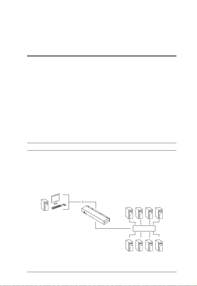
The KN1000A is a control unit that provides remote BIOS-level access to
servers or “over-IP” capability to KVM switches that do not have built-in overIP functionality. It allows operators to monitor and access their computers from
remote locations using a standard Internet browser or Windows and Java based
application. In addition, the KN1000A offers out-of-band access, including
external modem support, and supports BIOS-level troubleshooting without the
need for constant on-site IT maintenance.
To help you manage and control your entire data center environment, a builtin single-port power switch allows remote power management of a server/
installation connected locally to the KN1000A. You can also add a PON*
(Power Over the NET™) power management unit and remotely control the
power status of devices in your installation, including monitoring their current
status, as well as turning servers on, off, and rebooting them.
Note: Requires a separate purchase.
The KN1000A connects to the Internet, an Intranet, LAN, or WAN using
industry-standard Cat 5e cable, then uses a custom KVM cable to connect to a
local KVM switch or server. Because the KN1000A uses TCP/IP for its
communications protocol, the server or KVM switch it is connected to can be
accessed from any computer on the net – whether that computer is located
down the hall, down the street, or half-way around the world.
(Continues on next page.)
1

KN1000A User Manual
Operators at remote locations connect to the KN1000A via its IP address. Once
a connection has been established and authorization granted, the remote
computer can exchange keyboard, video and mouse signals with the server (or
servers on a KVM switch installation), just as if they were physically present
and working on the equipment directly.
The KN1000A’s Virtual Media function allows you to perform diagnostic
testing, file transfers, and OS and application patches from a remote console.
There is no need to physically load a CD directly to the server to perform datarelated tasks – you can conveniently and efficiently troubleshoot and resolve
problems at the BIOS level from anywhere.
The Administrator and Client software included with the KN1000A make it
easy to install, maintain, and operate. System administrators can handle a
multitude of tasks with ease – from installing and running GUI applications, to
BIOS-level troubleshooting, routine monitoring, concurrent main tenance,
system administration, rebooting and even pre-booting functions.
The Administrator Utility is available in a browser-based version as well as
Windows-based and Java application versions. The utility is used to configure
the system; limit access from remote computers; manage users; and maintain
the system with firmware and software module updates.
A Windows Client Viewer and a Java Applet Viewer are available for browser
access, while Windows Client AP and Java Client AP programs are provided
for non-browser GUI access. They allow IP connections and logins from
anywhere on the net. Inclusion of a Java-based client ensures that the
KN1000A is platform independent, and is able to work with practically all
operating systems. The KN1000A also provides serial console manageme nt
over the Internet, which can remotely control serial console devices such as a
network switch.
The client software allows access to, and control of, the connected servers.
Once an operator successfully connects and logs in, his screen displays what is
running on the remote unit attached to the KN1000A (a KVM OSD display, a
server's desktop, or a running program, for example) and he can control it from
his console just as if he were there.
The Log Server records all the events that take place on selected KN1000A
units for the administrator to analyze.
As an investment, the KN1000A is protected through the ability of its firmware
to be upgraded over the Internet. You can stay current with the latest
functionality improvements by downloading firmware update files from our
website as they become available, and then using the utility to quickly and
conveniently perform the upgrade.
2

Chapter 1. Introduction
Features and Benefits
The features and benefits provided by a KN1000A deployment are described
in the following table:
Features Benefits
Over-IP
Capability for
Legacy KVM
Switches or KVM
switches that do
not have built-in
over-IP
functionality
Configuration and
Operation
Remote Power
Control with
Wake on LAN
Superior Video With its enhanced FPS throughput for crisp responsive video
Virtual Media USB 1.1 and 2.0 devices (floppy drives, CDROMs, flash drives,
Virtual Remote
Desktop
Protects your original KVM switch investment. No need to
purchase new KVM switches to achieve the benefits of over-IP
connectivity.
Compatible KVM Switches include the following: ACS1208A,
ACS1216A, CS1308, CS1316, CS1708A, CS1716A, CS1754*,
CS1758*, CS9134, CS9138, KH1508A, KH1516A, KH2508A,
KH2516A.
*Some of the KN1000’s features may not be suppo rte d, depending on the functionality of
the connected KVM switch. (For example, some switches do not support virtual media.)
*Some features found on the connected KVM switches may not be supported on the
KN1000. (For example, the CS1754’s audio.)
An easy-to-navigate graphical user interface makes for convenient,
intuitive configuration and operation. Web-based Windows and
Java implementations allow the remote equipment to be controlled
from industry-standard web browsers. Windows and Java AP client
software – using the same, convenient, GUI – are also included to
provide access where a browser environment is not desired.
1. A built-in single-port power switch allows remote power
management of a server/installation connected locally to the
KN1000A.
2. In addition, you can also add a PON (Power Over the NET™)
power management unit and remotely control the power status of
devices on your installation, including monitoring their current
status, as well as turning servers On, Off and Rebooting them.
display, the KN1000A offers resolutions of up to 1920 x 1200 @
60Hz and vibrant 24-bit color depth for rich remote session display.
The remote desktop can appear full-screen, or in a window. In fullscreen mode the remote desktop display scales to the user’s
monitor display size.
etc.), folders, and image files on a user’s local system, appear and
act as if they were installed on the remote server, for ease and
convenience when performing software installation and system
updates across the entire installation.
On-screen keyboard with multilanguage support
Exit Macros support
BIOS-level access
3

KN1000A User Manual
Features Benefits
Smart Card / CAC
Reader Support
Built-in Single
Port Power
Switch
Low Bandwidth
Optimization
Multi-Platform /
Multi-Protocol
Support
Manage Browser
Access Methods
Multi-Keyboard
Language
Support /
On-Screen
Keyboard
Multi-Users /
Multi-Logins
Message Board To alleviate the possibility of access conflicts that may result from
To meet advanced security requirements, the KN1000A’s Virtual
Media function allows a Smart Card / CAC reader on a user’s local
system to be mapped to a remote server.
Allows remote power management of a server/installation
connected locally to the KN1000A, including turning servers On,
Off and Rebooting
Bandwidth optimization via grayscaling and video quality settings
allow maximum data throughput in low bandwidth situations. PPP
modem dialup support ensures reliable connectivity for out-ofband, and low bandwidth situations.
Windows and Java client software ensures that the KN1000A and
the equipment that connects to it can be accessed from most of the
operating systems in use today (Windows, Linux, Unix, Sun, Mac).
The KN1000A also supports a broad range of communication
protocols, such as TCP/IP, HTTP, HTTPS, UDP, DHCP, SSL, ARP,
DNS, ICMP, CHAP, PPP, 10Base-T and 100Base-T.
Use either HTTP, HTTPS, or disable the browser.
The KN1000A supports multiple keyboard language inputs –
including English, French, German, Italian, Spanish, Japanese,
Korean, and Traditional Chinese. There is no need to have a
separate keyboard for each language – you can input key data in
any of these languages with the KN1000A's convenient on-screen
keyboard.
The KN1000A supports up to 64 user accounts, and allows up to
32 concurrent user logins for single-bus access.
multiple user logins, and facilitate communication among the
logged-in users, a message board – similar to an Internet chat
program – allows users to communicate with each other, and
provides mechanisms for a user to take exclusive control of the
KVM functions.
4

Chapter 1. Introduction
Features Benefits
Advanced
Security
Advanced security features include password protection –
whereby a valid username and password must be given before
the client software will run – and advanced encryption
technologies, such as secure 128-bit SSL.
Supports SSL 128-bit data encryption and RSA 1024-bit
certificates for secure users logging in from a browser.
Flexible encryption design allows users to choose any
combination of 56-bit DES, 168-bit 3DES 256-bit AES, 128-bit
RC4, or Random for independent KB/Mouse, video, and virtual
media data encryption.
IP/MAC Filter for enhanced security protection
Supports password protection
Private CA
External
Authentication
Support
Event Logging The KN1000A can record all the events that take place on it and
Console
Management
In addition to its own security protection, the KN1000A allows you
to set up login authentication and authorization management from
a external sources such as RADIUS, LDAP, LDAPS, and MS Active
Directory.
write them to a searchable database. Administrators and selected
users can search for events containing specific words or strings
and retrieve them according to date and order of significance.
Serial console management – serial terminal access. Access the
KN1000A via a built-in serial viewer, or via third-party software
(such as PuTTY) for Telnet and SSH sessions.
Out of Band Support – via dial up modem support. Access the
KN1000A through its RS-232 port using a dial-up connection.
Upgradeable
Firmware over
the Internet
Mouse DynaSync No need to resync your mouse – Mouse DynaSync provides
Auto-Ping Pings a device to determine its status; if the ping test fails after a
Supports Multiple
Interfaces
No need to add yet another cable to your installation – stay current
with the latest functionality improvements and updates, all over the
Internet.
automatic locked-in synching of the remote and local mouse
pointers – eliminating the need to constantly resync the two
movements. Your local console mouse movement becomes the
remote unit’s mouse movement.
set amount of time it automatically takes an action assigned.
Supports PS/2, USB, Sun Legacy (13W3)* and serial (RS-232)
connectivity
*Requires CV130A converter purchase
5

KN1000A User Manual
Features Benefits
Full-Screen or
Sizable Remote
Desktop Window
DDNS Allows the mapping of a dynamic IP address assigned by a DHCP
On/Off
Scheduling for
Power Outlets
Safe Shutdown
Support
End Session Administrators can terminate running sessions
Magic Panel Special hideaway control panel with configurable function icons.
Get a full screen even if your monitor’s resolution is lower than the
remote computer’s resolution. In full-screen mode the remote
desktop display scales to the user’s monitor display size. Supports
up to 1920 x 1200 @ 60Hz; 24-bit color depth for remote sessions.
server to a host name.
Power management tasks can be scheduled on a daily, weekly,
monthly or user-specified time basis
IT administrators can control servers remotely and completely shut
down servers before powering them off.
6

Chapter 1. Introduction
System Requirements
Remote User Computers
Remote user computers (also referred to as client computers) are the ones the
users log into the switch with from remote locations over the Internet (see
Terminology, page xiii). The following equipment must be installed on these
computers:
For best results, we recommend that the computers used to access the
switch have at least a P III 1 GHz processor, with their screen resolution
set to 1024 x 768.
Browsers must support 128-bit SSL encryption.
For best results, a network transfer speed of at least 128 kbps is
recommended.
For the Log Server, you mus t have the Micros oft Jet O LEDB 4.0 or hi gher
driver installed.
For Safe Shutdown:
The computer must be running Windows (2000 or higher), or Linux.
The Safe Shutdown program (available by download from our
website), must be installed and running on the computer.
Servers
Servers are the computers connected to the switch via KVM Cables (see
Terminology, page xiii). The following equipment must be installed on these
servers:
A VGA, SVGA or multisync port.
For USB KVM Cable Connections: a Type A USB port and USB host
controller.
For PS/2 KVM Cable Connections: 6-pin Mini-DIN keyboard and mouse
ports.
7

KN1000A User Manual
Cables
One custom KVM cable set (1 USB, 1 PS/2) to link the KN1000A to a
server or KVM switch are provided with this package.
Custom KVM cable sets are available in various lengths, as shown in the
table below:
Cable Type Length CS Part Number
PS/2 1.2 m 2L-5201P
1.8 m 2L-5202P
1.8 m 2L-5702P
3.0 m 2L-5203P
6.0 m 2L-5206P
USB 1.2 m 2L-5201U
1.8 m 2L-5202U
3.0 m 2L-5203U
5.0 m 2L-5205U
PS/2-USB 1.2 m 2L-5301UP
1.8 m 2L-5302UP
3.0 m 2L-5303UP
To purchase additional cable sets, contact your dealer.
One custom Console cable set to link the KN1000A to a local console is
provided with this package.
Note: This cable set has been designed to operate with either PS/2 or USB
consoles.
A USB 2.0 cable for use with the Laptop USB Console function (see
(LUC) Port, page 11) is provided with this package.
Cat 5e or higher Ethernet cable (not provided with this package), should be
used to connect the KN1000A to the LAN, WAN, or Internet.
One power cable to connect the KN1000A to the server for power
management functionality is provided with this package.
8
Chapter 1. Introduction
Video
Only the following non-interlaced video signals are supported:
Resolution Refresh Rates
640 x 480 60, 72, 75, 85, 90, 100, 120
720 x 400 70
800 x 600 56, 60, 72, 75, 85, 90, 100, 120
1024 x 768 60, 70, 75, 85, 90, 100
1152 x 864 60, 70, 75, 85
1280 x 720 60
1280 x 1024 60, 70, 75, 85
1920 x 1200 60
Operating Systems
Supported operating systems for remote user computers that log in to the
KN1000A include Windows XP (and higher), and other systems capable
of running Sun's Java Runtime Environment (JRE) 6, Update 3, or higher
(Linux, Mac, Sun, etc.).
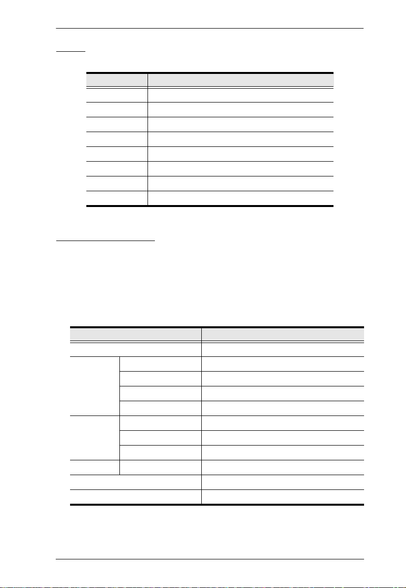
Supported operating systems for servers that connect to the KN1000A are
shown in the table, below:
OS Version
Windows XP and higher
Linux RedHat 7.1 and higher
Fedora Core12 and higher
SuSE 11.1 and higher
Mandriva (Mandrake) 9.0 and higher
UNIX AIX 7.1 and higher
FreeBSD 10.1 and higher
Sun Solaris 10 and higher
Novell Netware 6.5 and higher
Mac OS X 10.7 and higher
DOS 6.2 and higher
9
KN1000A User Manual
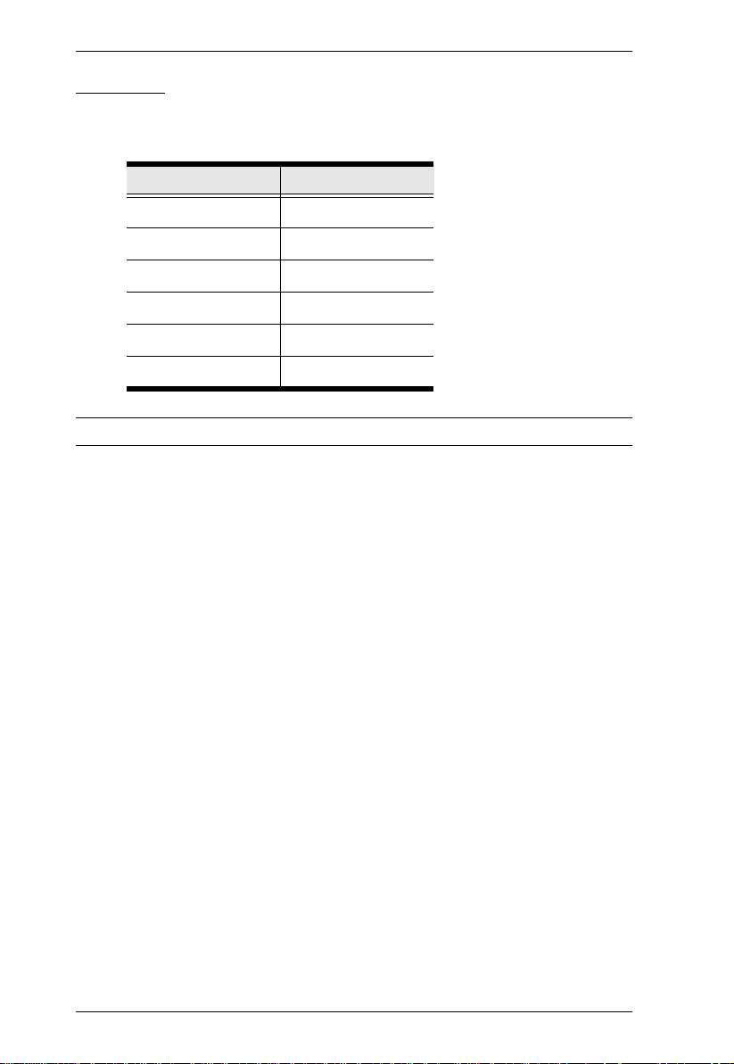
Browsers
Supported browsers for users that log in to the KN1000A include the
following:
Browser Version
IE 10 and higher
Firefox 3.5 and higher
Mozilla 3.5 and higher
Safari* 2.0 and higher
Opera 9.0 and higher
Netscape 8.1 and higher
* See Mac Systems, page 184, for further information regarding Safari.
10
Chapter 1. Introduction
13
4
5
6
7
2
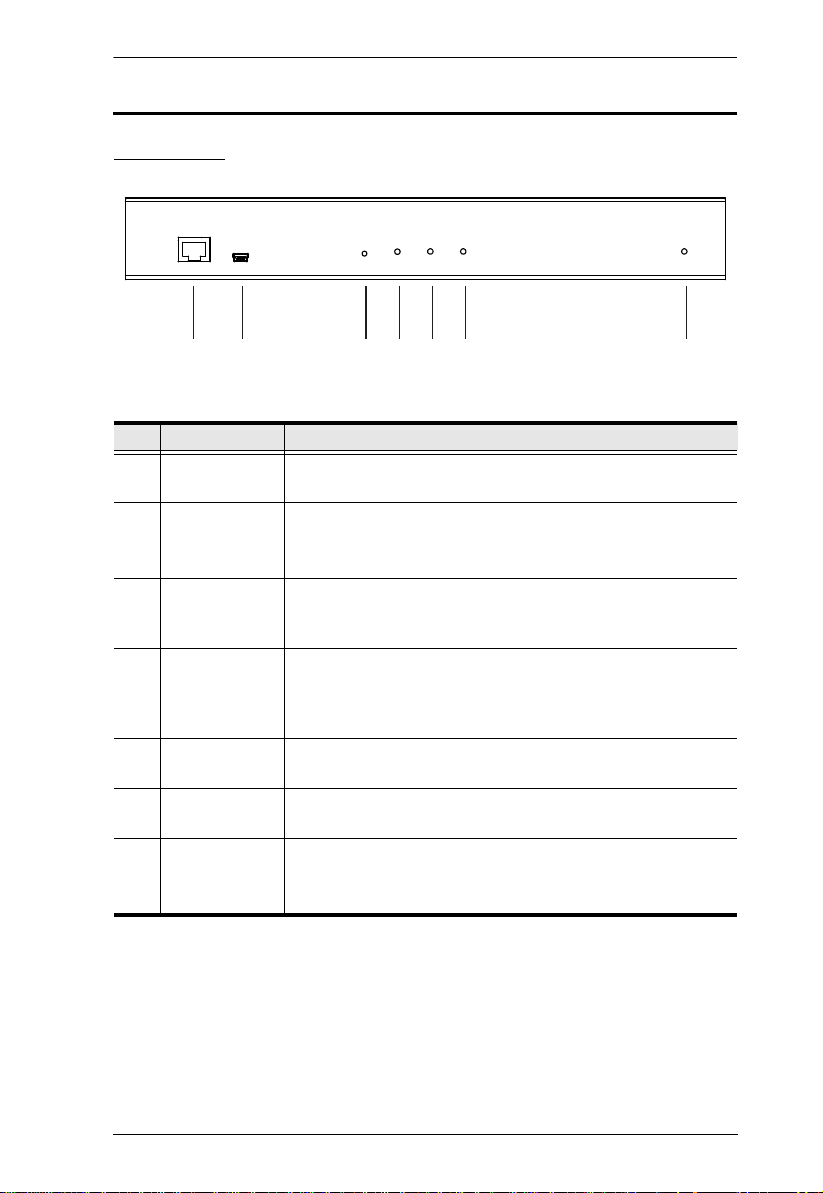
Components
Front View
No. Component Description
1 LAN Port The Cat 5e cable that connects the KN1000A to the LAN,
WAN, or Internet plugs in here.
2 Laptop USB
Console
(LUC) Port
3 Firmware
Upgrade /
Reset Switch
4 10/100/1000
Mbps LED
5 Link LED Flashes GREEN to indicate that a Client program is accessing
6 Power LED Lights ORANGE when the KN1000A is powered up and ready
7 Power Outlet
LED
This port is used to connect a laptop to the KN1000A for KVM
access to the computers or switch.
This semi-recessed pushbutton can be used to reset the
switch, or to upgrade the firmware.
The LED lights ORANGE to indicate a 10 Mbps data
transmission speed. It lights ORANGE+GREEN to indicate a
100 Mbps data transmission speed. It lights GREEN to
indicate a 1000 Mbps data transmission speed.
the device.
to operate.
Lights ORANGE when the server attached to the KN1000A’s
power outlet is powered on
11
KN1000A User Manual
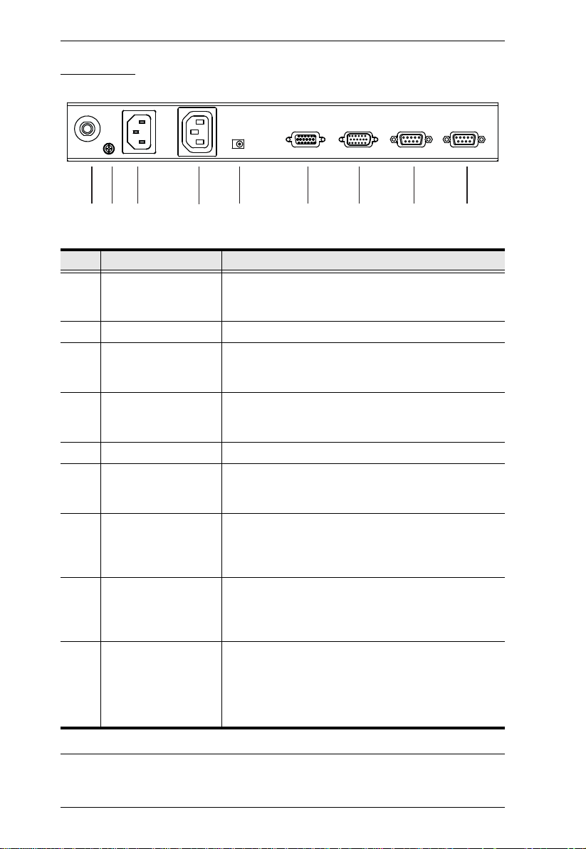
Rear View
12 3 4 5 67 8 9
No. Component Description
1 Circuit Breaker As a safety measure, if there is an overcurrent
2 Grounding Terminal The wire used to ground the unit connects here.
3 Power Inlet The power cord that connects the KN1000A to an AC
4 Power Outlet The power cord provided with the KN1000A package
5 Power Jack The power adapter cable plugs in here.
6 PC/KVM Port The KVM cable provided with this package that links
7 PS/2 – USB Console
Port
8 PON Port This port is made available for use with a Power over
9 RS-232 Port This serial port is provided for:
situation, the circuit breaker will trip. Press this button
to recover normal operation.
power source for power management functionality
plugs in here.
that connects to the server for power management
plugs in here. See Power Management, page 52.
the KN1000A to your server / KVM switch plugs in
here.
The cable for the local console (keyboard, monitor,
and mouse) plugs in here. The console can use either
a PS/2 or USB keyboard and mouse. Each connector
is color coded and marked with an appropriate icon.
the NET™ remote power management module. Refer
to the User Manual that came with the PON device for
operation details.
1. Serial console management (see Serial Console,
page 63 for details); or
2. Out-of-band modem operation (see OOBC,
page 60 for details).
12
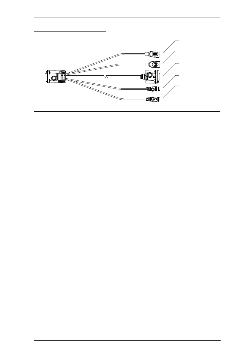
Chapter 1. Introduction
USB Keyboard
USB Mouse
Video
PS/2 Keyboard
PS/2 Mouse
Custom Console Cable
Note: You can use any combination of keyboard and mouse connections. For
example, you can use a PS/2 keyboard with a USB mouse.
13

KN1000A User Manual
This Page Intentionally Left Blank
14
Chapter 2
1. Important safety information regarding the placement of this device is
provided on page 137. Please review it before proceeding.
2. Make sure that the power to any device that you connect to the
installation has been turned off. You must unplug the power cords of
any computers that have the Keyboard Power On function.
3. Any installation that does not follow the instructions in this guide may
be hazardous.
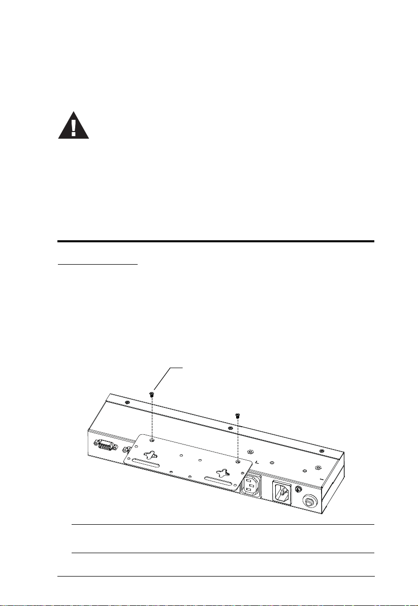
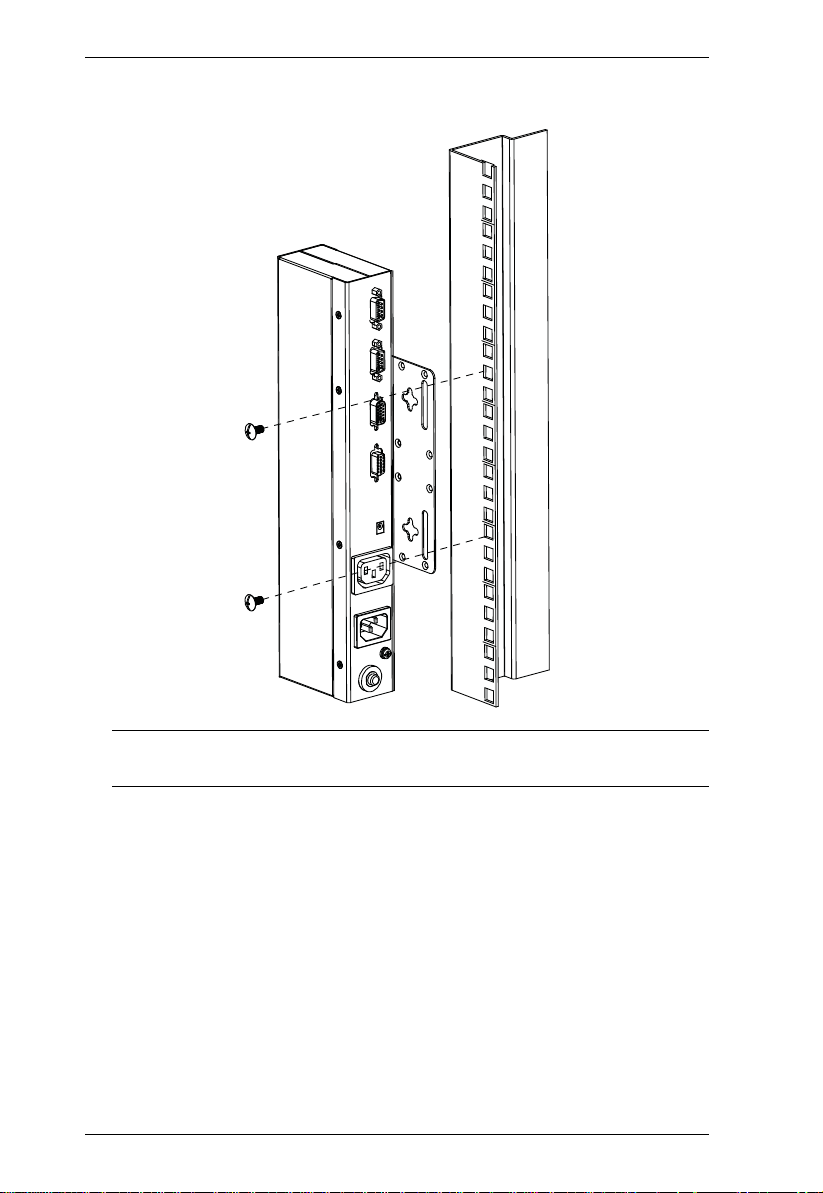
M3*5 Screw
Hardware Setup
Mounting
Rack Mounting
For convenience and flexibility, the KN1000A can be mounted on a system
rack. To rack-mount the unit, do the following:
1. Remove the two original screws from the top/bottom of the unit (near the
rear of the unit).
2. Using the screws provided with the Rack Mount kit, screw the mounting
bracket into the KN1000A – as shown in the diagram below:
Note: The illustrations show the mounting bracket attached to the bottom
of the unit; it can also be attached to the top.
15
KN1000A User Manual
3. Screw the bracket into any convenient location on th e rack.
Note: Rack screws are not provided. Use screws that are appropriate for
your rack.
16
 Loading...