

ATEN KM-0432 Instruction Manual
FCC Information
This is an FCC Class A product. In a domestic environment this product may cause
radio interference in which case the user may be required to take adequate measures.
This equipment has been tested and found to comply with the limits for a Class A
digital device, pursuant to Part 15 of the FCC Rules. These limits are designed to
provide reasonable protection against harmful interference when the equipment
is operated in a commercial environment. This equip ment generates, uses and can
radiate radio frequency energy and, if not installed and used in accordance with
the instruction manual, may cause harmful interference to radio communications.
Operation of this equipment in a residential area is likely to cause harmful
interference in which case the user will be required to correct the interference at
his own expense.
© Copyright 2003 ALTUSEN® PAPE-0213-1AX
All brand names and trademarks are the registered property of their respective owners.
2003-12-15

Package Contents
The complete KM0432 package consists of the following components:
M 1 KM0432 Modular Matrix KVM Switch
M 1Power Cord
M 1 User Manual
M 1 Quick Start Guide
M 1 Warranty Registration Card
Check to make sure that all of the components are present and in good order. If
anything is missing, or was damaged in shipping, contact your dealer.
Read this manual thoroughly and follow the installation and operation
procedures carefully to prevent any damage to the switch or to any other
devices on the KM0432 installation.
2003-12-15
ii

Contents
Chapter 1
Introduction
Benefits . . . . . . . . . . . . . . . . . . . . . . . . . . . . . . . . . . 2
Features . . . . . . . . . . . . . . . . . . . . . . . . . . . . . . . . . . 2
Hardware Requirements . . . . . . . . . . . . . . . . . . . . . . . . . . 4
Console . . . . . . . . . . . . . . . . . . . . . . . . . . . . . . . . 4
Computers . . . . . . . . . . . . . . . . . . . . . . . . . . . . . . . 4
Cables . . . . . . . . . . . . . . . . . . . . . . . . . . . . . . . . . 4
KM0432 Front View . . . . . . . . . . . . . . . . . . . . . . . . . . . 5
KM0432 Rear View . . . . . . . . . . . . . . . . . . . . . . . . . . . . 7
Console Modules . . . . . . . . . . . . . . . . . . . . . . . . . . . . . 8
Console Modules Front View . . . . . . . . . . . . . . . . . . . . . 8
Console Modules Rear View . . . . . . . . . . . . . . . . . . . . . 9
Chapter 2
Installation
Overview . . . . . . . . . . . . . . . . . . . . . . . . . . . . . . . . . . 11
Before you Begin . . . . . . . . . . . . . . . . . . . . . . . . . . . . . 12
Single Stage Installation . . . . . . . . . . . . . . . . . . . . . . . . . . 12
Multilevel Installations . . . . . . . . . . . . . . . . . . . . . . . . . . 16
Overview . . . . . . . . . . . . . . . . . . . . . . . . . . . . . . . 16
Daisy Chaining . . . . . . . . . . . . . . . . . . . . . . . . . . . . 17
Cascading . . . . . . . . . . . . . . . . . . . . . . . . . . . . . . . 19
Daisy Chaining Plus Cascading Expansion . . . . . . . . . . . . . . . . 24
Protocol Interface Expansion . . . . . . . . . . . . . . . . . . . . . 24
Physical Interface Expansion . . . . . . . . . . . . . . . . . . . . . 26
Topology Considerations . . . . . . . . . . . . . . . . . . . . . . . . . 27
Basic Operations . . . . . . . . . . . . . . . . . . . . . . . . . . . . . . 27
Hot Plugging . . . . . . . . . . . . . . . . . . . . . . . . . . . . . 27
Powering Off and Restarting . . . . . . . . . . . . . . . . . . . . . 27
Port Selection . . . . . . . . . . . . . . . . . . . . . . . . . . . . . 28
Port ID Numbering . . . . . . . . . . . . . . . . . . . . . . . . . . 29
User Management and Security . . . . . . . . . . . . . . . . . . . 30
2003-12-15
iii

Chapter 3
OSD Operation
OSD Overview . . . . . . . . . . . . . . . . . . . . . . . . . . . . . . 33
OSD Main Screen Headings . . . . . . . . . . . . . . . . . . . . . . . 35
OSD Navigation . . . . . . . . . . . . . . . . . . . . . . . . . . . . . . 35
OSD Functions . . . . . . . . . . . . . . . . . . . . . . . . . . . . . . 36
F1 GOTO: . . . . . . . . . . . . . . . . . . . . . . . . . . . . . . . 36
F2 LIST: . . . . . . . . . . . . . . . . . . . . . . . . . . . . . . . 37
F3 SET: . . . . . . . . . . . . . . . . . . . . . . . . . . . . . . . . 38
F4 ADM: . . . . . . . . . . . . . . . . . . . . . . . . . . . . . . . 40
F5 SKP: . . . . . . . . . . . . . . . . . . . . . . . . . . . . . . . . 44
F6 BRC: . . . . . . . . . . . . . . . . . . . . . . . . . . . . . . . . 45
F7 SCAN: . . . . . . . . . . . . . . . . . . . . . . . . . . . . . . . 46
F8 LOUT: . . . . . . . . . . . . . . . . . . . . . . . . . . . . . . . 47
Cascaded OSD Operation . . . . . . . . . . . . . . . . . . . . . . . . . 48
Chapter 4
Hotkey Operation
Hotkey Port Control . . . . . . . . . . . . . . . . . . . . . . . . . . . . 49
Invoking Hotkey Mode . . . . . . . . . . . . . . . . . . . . . . . . 49
Selecting the Active Port . . . . . . . . . . . . . . . . . . . . . . . 50
Auto Scanning . . . . . . . . . . . . . . . . . . . . . . . . . . . . 51
Skip Mode . . . . . . . . . . . . . . . . . . . . . . . . . . . . . . 53
Hotkey Beeper Control . . . . . . . . . . . . . . . . . . . . . . . . . . 54
Hotkey Summary Table . . . . . . . . . . . . . . . . . . . . . . . . . . 54
Chapter 5
Multiplatform Support
Sun Keyboard Emulation . . . . . . . . . . . . . . . . . . . . . . . . . 56
Mac Keyboard Emulation . . . . . . . . . . . . . . . . . . . . . . . . . 57
2003-12-15
iv

Chapter 6
The Firmware Upgrade Utility
Introduction . . . . . . . . . . . . . . . . . . . . . . . . . . . . . . . . 59
Purpose . . . . . . . . . . . . . . . . . . . . . . . . . . . . . . . . 59
Before You Begin . . . . . . . . . . . . . . . . . . . . . . . . . . . 60
Performing the Upgrade . . . . . . . . . . . . . . . . . . . . . . . . . . 61
Starting the Upgrade . . . . . . . . . . . . . . . . . . . . . . . . . 61
Upgrade Failure . . . . . . . . . . . . . . . . . . . . . . . . . . . . 65
Appendix
Connection Tables . . . . . . . . . . . . . . . . . . . . . . . . . . . . . 67
KM0432 Daisy Chain . . . . . . . . . . . . . . . . . . . . . . . . . 67
KM0432 Cascade to ATEN CS-138A . . . . . . . . . . . . . . . . 67
OSD Factory Default Settings . . . . . . . . . . . . . . . . . . . . . . . 68
Clear Login Information . . . . . . . . . . . . . . . . . . . . . . . . . . 69
Specifications . . . . . . . . . . . . . . . . . . . . . . . . . . . . . . . 70
KM0432 . . . . . . . . . . . . . . . . . . . . . . . . . . . . . . . . 70
Console Modules . . . . . . . . . . . . . . . . . . . . . . . . . . . 71
KVM Adapter Cables . . . . . . . . . . . . . . . . . . . . . . . . . 71
Troubleshooting . . . . . . . . . . . . . . . . . . . . . . . . . . . . . . 72
Limited Warranty . . . . . . . . . . . . . . . . . . . . . . . . . . . . . 72
2003-12-15
v

About This Manual
This User Manual provides information on all aspects of installing, configuring
and operating your KM0432 Modular Matrix KVM switch. An overview of
the information found in the manual is provided below.
Overview
Chapter 1, Introduction, introduces you to the KM0432 System. Its purpose,
features and benefits are are presented; its front and back panel components are
explained; and the modules used to connect to it are described.
Chapter 2, Installation takes you through the KM0432’s installation procedres
— from a basic single stage hookup to a complete daisy chained plus cascaded
installation.
Chapter 3, OSD Operation, provides detailed information for configuring
and controlling your installation using the KM0432’s intuitive, mouse-driven
OSD (On Screen Display) menus.
Chapter 4, Hotkey Operation, explains the concepts and procedures used in
controlling the KM0432 from the keyboard.
Chapter 5, Multiplatform Support,
Chapter 6, The Firmware Upgrade Utility, explains how to upgrade the
KM0432’s firmware with the latest available versions.
Appendix An Appendix at the end of the manual provide technical and other
important information regarding the KM0432.
2003-12-15
vi

Conventions
This manual uses the following conventions:
Courier
Indicates text that you should key in.
[ ]
Indicates keys you should press. For example, [Enter] means to
press the Enter key. If keys need to be chorded, they appear
together in the same bracket with a plus sign betw een th em :
[Ctrl+Alt].
1.
Numbered lists represent procedures with sequential steps.
M
Bullet lists provide information
>
Indicates selecting an option on a menu. For example, Start >
Run means to open the Start menu, and then select Run.
Indicates critical information.
Getting Help
For additional help, advice, and information, ALTUSEN provides several
support options. If you need to contact ALTUSEN technical support with a
problem, please have the following information ready beforehand:
M Product model number, serial number, and date of purchase.
M Your computer configuration, including operating system, revision level,
expansion cards, and software.
M Any error messages displayed at the time the error occurred.
M The sequence of operations that led up to the error.
M Any other information you feel may be of help.
2003-12-15
vii

ALTUSEN Technical Support
North America Technical
Phone Support
Registered ALTUSEN product owners are entitled to
telephone technical support. Call the ALTUSEN
Technical Support Center: 949-453-8885.
International Technical Phone
Support
1. Contact your local dealer.
2. Call the ALTUSEN Technical Support Center:
(886-2) 8692-6959.
Email Support Email your questions and concerns to:
support@altusen.com
Online Troubleshooting The ALTUSEN support website:
http://www.altusen.com/support
provides online troubeshooting that describes the
most commonly encountered problems and offers
possible solutions to them.
Online Documentation User Manuals are available electronically at the
ALTUSEN support website:
http://www.altusen.com/support
Software Updates Download the latest drivers and firmware for your
product from the ALTUSEN support website:
http://www.altusen.com/support
Product Information
For information about all of ALTUSEN’s products and how they can help you
connect without limits, visit ALTUSEN on the webat http://www.altusen.com
ALTUSEN Authorized Resellers
ALTUSEN provides the following ways to find an authorized reseller in your area:
M In the United States of America, call: 866-ALTUSEN
M In Canada and South America, call: 949-453-8885
M In all other locations, call: 886-2-8692-6959
M Visit ALTUSEN on the web at http://www.altusen.com for a list of locations
and telephone numbers
2003-12-15
viii

Chapter 1.
Introduction
The KM0432 Matrix KVM Switch is designed to give IT administrators in
large corporations advanced control of multiple servers. It allows operators
working at up to four keyboard, mouse, and monitor consoles to simultaneously
and independently take direct control of up to 32 computers. With a
combination of daisy chaining and cascading, up to 32 operators can acces s an d
control up to 4096 computers.
The four consoles belonging to the Master unit (the highest level KM0432) can
access all the computers on the installation - those that are directly connected as
well as those that are daisy chained and cascaded (up to 4096). The four
consoles belonging to each of the Slave units (the daisy chained KM0432s),
however, can only access the computers that are connected to th em on th e s am e
daisy chain level (directly and cascaded - up to 256).
The KM0432 features a Console Module design with automatic console
conversion that allows any combination PS/2 and USB consoles to control any
combination of PS/2, USB, or Sun computers. The KM0432’s RJ-45 CPU
connectors, combined with Auto Signal Compensation (ASC), allow signals to
travel up to 500 feet (150 meters) away and still maintain high video resolution;
eliminating the the need for KVM extenders, and allowing the installation to take
advantage of the internal CAT 5e and CAT6 wiring built in to most modern
commercial buildings. In addition, use of RJ-45 connectors saves precious IT real
estate by allowing a full 32 CPU ports to reside in a single 1U system case.
Setup is fast and easy; plugging cables into their appropriate ports is all that is
entailed. Because the KM0432 intercepts keyboard and mouse input directly,
there is no software to configure, so there is no need to get involved in complex
installation routines or be concerned with incompatibility problems.
Access to any computer is easily accomplished eith er by en tering Hotkey
combinations from the keyboard, or by means of a powerful menu driven OSD
(On Screen Display) system. A convenient Auto Scan feature also permits
automatic scanning and monitoring of the activities of all computers running on
the installation one by one.
2003-12-15
1

Benefits
The KM0432 Matrix KVM switch saves time and money by allowing a single
console to manage each of the connected computers. A KM0432 installation
provides the following benefits:
M Eliminates the cost of a keyboard, monitor, and mouse for each computer.
M Eliminates the need for the additional space of the extra components.
M Saves on energy costs.
M Eliminates the inconvenience, time and effort required to move from one
computer to another.
M Allows centralized control of computers located at non-contiguous locations
on the site.
Features
M Four consoles independently and simultaneously control up to 32 directly
connected computers
M Daisy chain up to 7 additional units
M Cascade up to 32 compatible KVM switches from each station on the chain
M Up to 32 consoles control up to 4,096 computers on a daisy
chained/cascaded installation
M Compact design - RJ-45 connectors allow rack mounting in a 19", 1U,
system rack
M Multiplatform support: PC, Mac and Sun
M Console conversion - any type of console can control any type of computer -
mixed combinations (PS/2 & USB) supported on both the console and
computer sides
M PS/2 keyboard and mouse emulation - computers boot even when the
console focus is elsewhere - Keep Alive feature ensures that the keyboard
and mouse work properly even if the switch temporarily loses power
M Hot pluggable; add or remove components without having to power off the
switch
2003-12-15
2

M No software required; convenient computer selection via intuitive hotkey
combinations or On Screen Display (OSD) menus
M OSD port list automatically expands when stations are added - port names
are automatically reconfigured when the station sequence is changed
M OSD screen automatically adjusts to resolution changes
M Auto Scan feature for monitoring user-selected computers
M Three level password security: Super Administrator, Administrator, and
Users
M LCD, VGA, SVGA, XGA, and MultiSync support; DDC2B
M Superior video quality - up to 1024 x 768 @ 60Hz for up to 150m; 1920 x
1440 at normal cable distances
M Auto Signal Compensation (ASC) assures optimum video resolution for
distances up to 150m between the switch and the consoles or computers - no
DIP switch setting required
M Lifetime firmware upgrading via flash ROM
2003-12-15
3
Hardware Requirements
Console
The following equipment must be used for each console:
M A VGA, SVGA, or Multisync monitor capable of the highest resolution that
you will be using on any computer in the installation.
M Either a PS/2 or a USB keyboard and mouse.
Computers
The following equipment must be installed on each computer:
M An HDB-15 video port or, for legacy Sun systems, a Sun 13W3 video port.
M Either a PS/2 style (6 pin mini-DIN) mouse port and PS/2 style keyboard
port; or USB ports (for a USB keyboard and USB mouse); or, for legacy Sun
systems, a Sun Sun style keyboard port (8 pin mini-DIN).
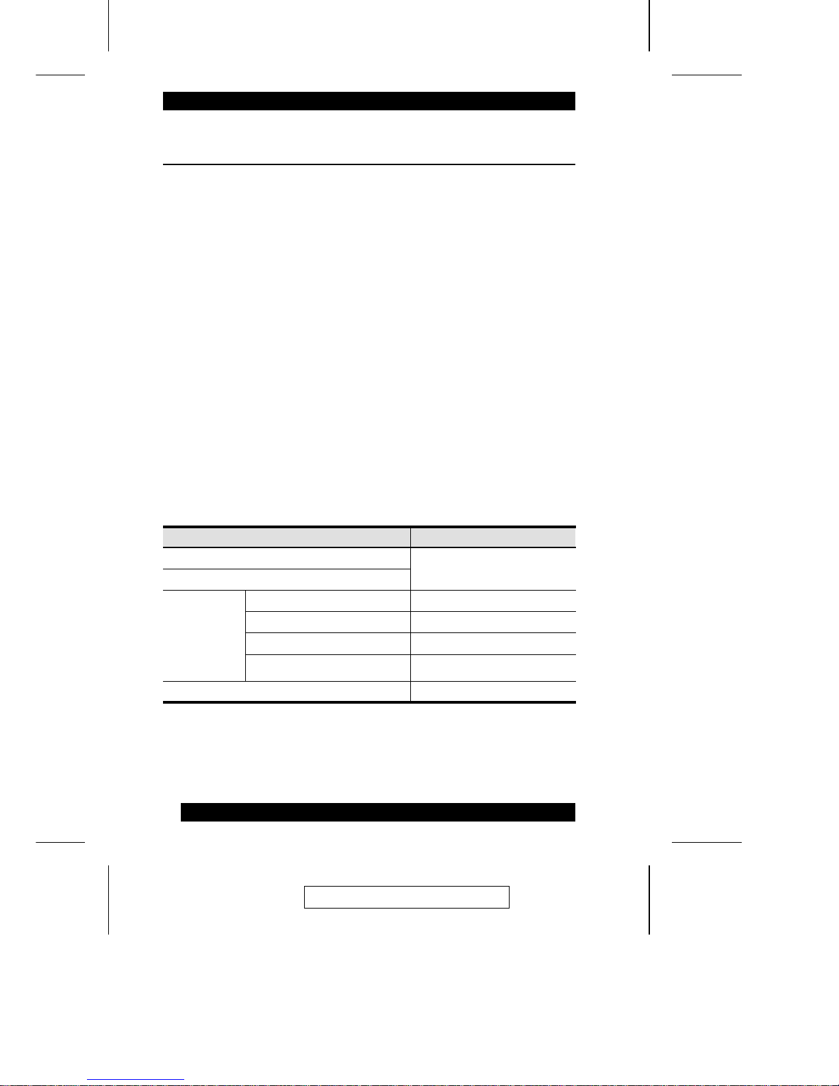
Cables
The following cables are required for use with the KM4032 Modular Matrix
KVM switch:
Function Cable
Console Module to KM0432 Cat. 5 cable
KM0432 to KVM Adapter Cable (see label 3, p. 14)
KVM Adapter
Cable
(To computer
or cascaded
KVM switch.)
For PS/2 ports KA9120
For USB ports KA9170
For Sun Legacy Computers KA9130
For Sun USB Computers KA9131
Daisy Chain Cable KC1800
2003-12-15
4
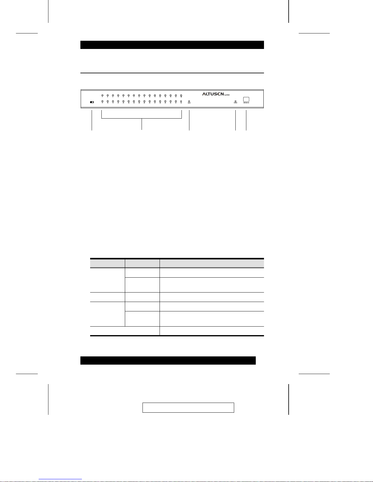
KM0432 Front View
1. Firmware Upgrade Recovery Switch
During normal operation and while performing a fimware upgrade, this
switch should be in the NORMAL position. If a firmware upgrade
operation does not complete successfully, slide this switch to the
RECOVER position and do a warm reset (see p. 6), to return the switch to
its prior firmware state.
After returning the switch to its prior firmware state, slide the switch back
to the NORMAL position to attempt the firmware upgrade again, or to use
the switch with its prior firmware.
2. Port LEDs
The Port LEDs are multicolored (Red / Green / Amber), and provide status
information about their corresponding CPU Ports as follows:
Color Condition Indication
Amber Steady Port is selected; connected computer is On
Flashing Port is selected; port is cascaded to a powered
on KVM switch
Red Steady Port is selected; connected computer is Off
Green Steady Port is not selected; connected computer is On
Flashing Port is not selected; port is cascaded to a
powered on KVM switch
Off Port is not selected; connected computer is Off
4-USER, 32-PORT MATRIX KVM MODEL NO. KM0432
31 4 5
2
2003-12-15
5

3. Reset Switch
Pressing this switch in performs a System Reset.
Note: This switch is semi-recessed and must be pushed with a thin object -
such as the end of a paper clip, or a ballpoint pen.
4. Power LED
Lights to indicate that the KM0432 is powered up and ready to go.
5. Station ID LED
The KM0432’s Station ID is displayed here. If this is a Single Station
installation (see p. 12), or the First Station on a Daisy Chained installation
(see p. 17), the KM0432 has a Station ID of 01.
On a Daisy Chained installation, the KM0432 auto-senses its position and
displays the Station ID that corresponds to its place in the chain. (see Port
ID Numbering, p. 29 for details).
2003-12-15
6
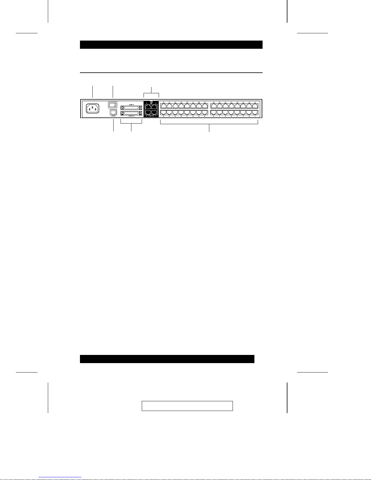
KM0432 Rear View
1. Power Socket
The power cord to the AC source plugs in here.
2. Power Switch
This is a standard rocker switch that powers the unit On and Off.
3. Console Port Section
The Cat. 5 cables from the Console Modules (see p. 8) plug in here.
4. Firmware Upgrade Port
The Firmware Upgrade Cable that transfers the firmware upgrade data
from the administrator’s computer to the KM0432 (see p. 60), plugs into
this RJ-45 connector.
5. Daisy Chain Ports
When Daisy Chaining Units (see p. 17), the daisy chain cables plug in here.
The upper port is the Chain In port; the lower one one is the Chain Out
port. The Chain In port is not used on the Master (First Stage) unit.
6. Computer Port Section
The Cat. 5 cables that link the KM0432 to KVM cables that connect to the
computers plug in here.
1
3
6
5
2
4
2003-12-15
7
Console Modules
The purpose of the Console Modules is to provide flexibility for your
installation by allowing PS/2 and USB interfaces to be mixed and matched at
the console side, and PS/2, USB and Sun interfaces to be mixed and match ed at
the computer side. With this approach, either type of console can acces s an d
control any type of computer. The modules currently available are shown in the
table below:
Module Type
KA9220 For PS/2 consoles
KA9270 For all USB consoles (including Mac
and Sun)
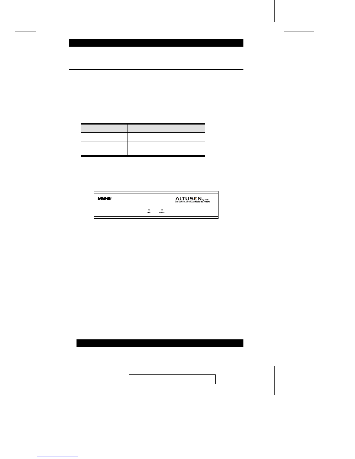
Console Modules Front View
Although, the KA9270 Module is shown in the diagram, the front panel
configuration of both modules is the same. It consists of two LEDs: Link and
Power.
M Link lights to indicate that the module is connected to the KM0432.
M Power lights to indicate that the module is turned On and receiving power.
1 2
2003-12-15
8
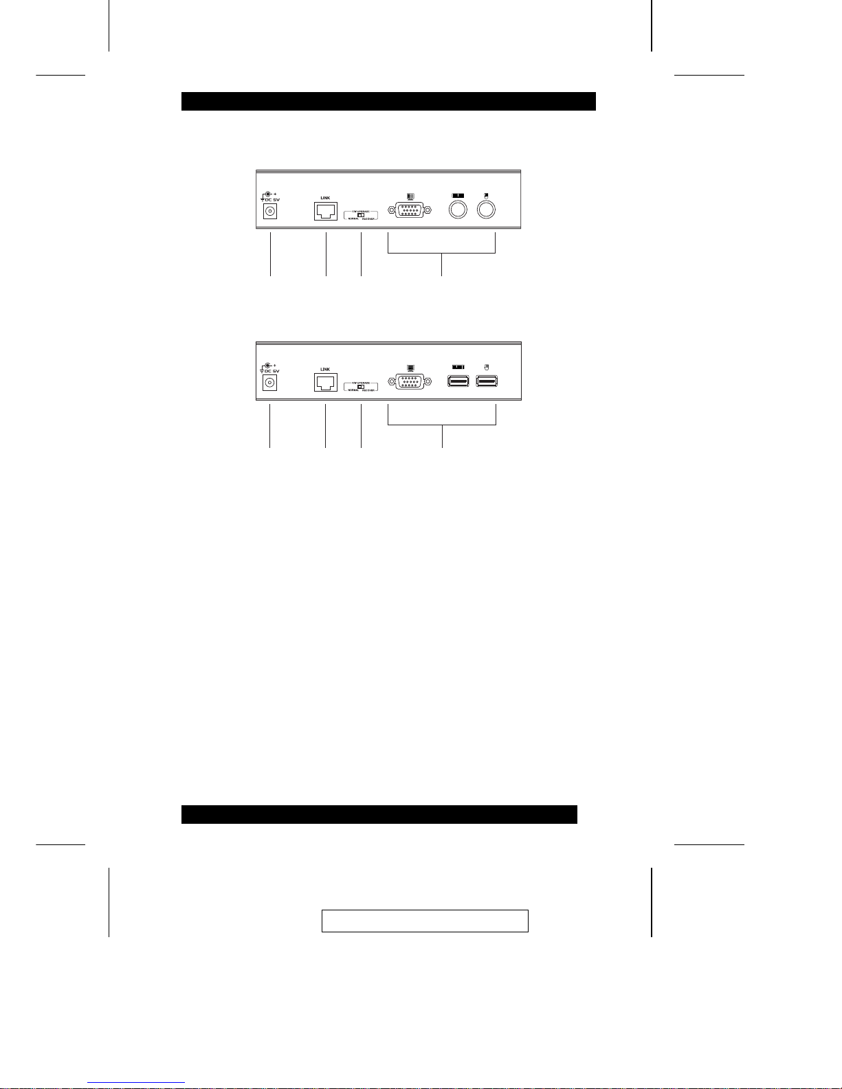
Console Modules Rear View
1. Power Jack
The power adapter cable plugs in here.
2. I/O Jack
The cable that links the module to the KM0432 plugs in here.
3. Firmware Upgrade Recovery Switch
During normal operation and while performing a fimware upgrade, this
switch should be in the NORMAL position. See p. 5 for details about this
switch.
4. Console Port Section
The cables from your keyboard, monitor and mouse plug in here. The
keyboard and mouse ports of both modules are labeled with an appropriate
icon to indicate which is which. The KA9220 ports are also color coded.
1 2 3
4
KA9220
1 2 3
4
KA9270
2003-12-15
9

Notes:
2003-12-15
10
Chapter 2.
Installation
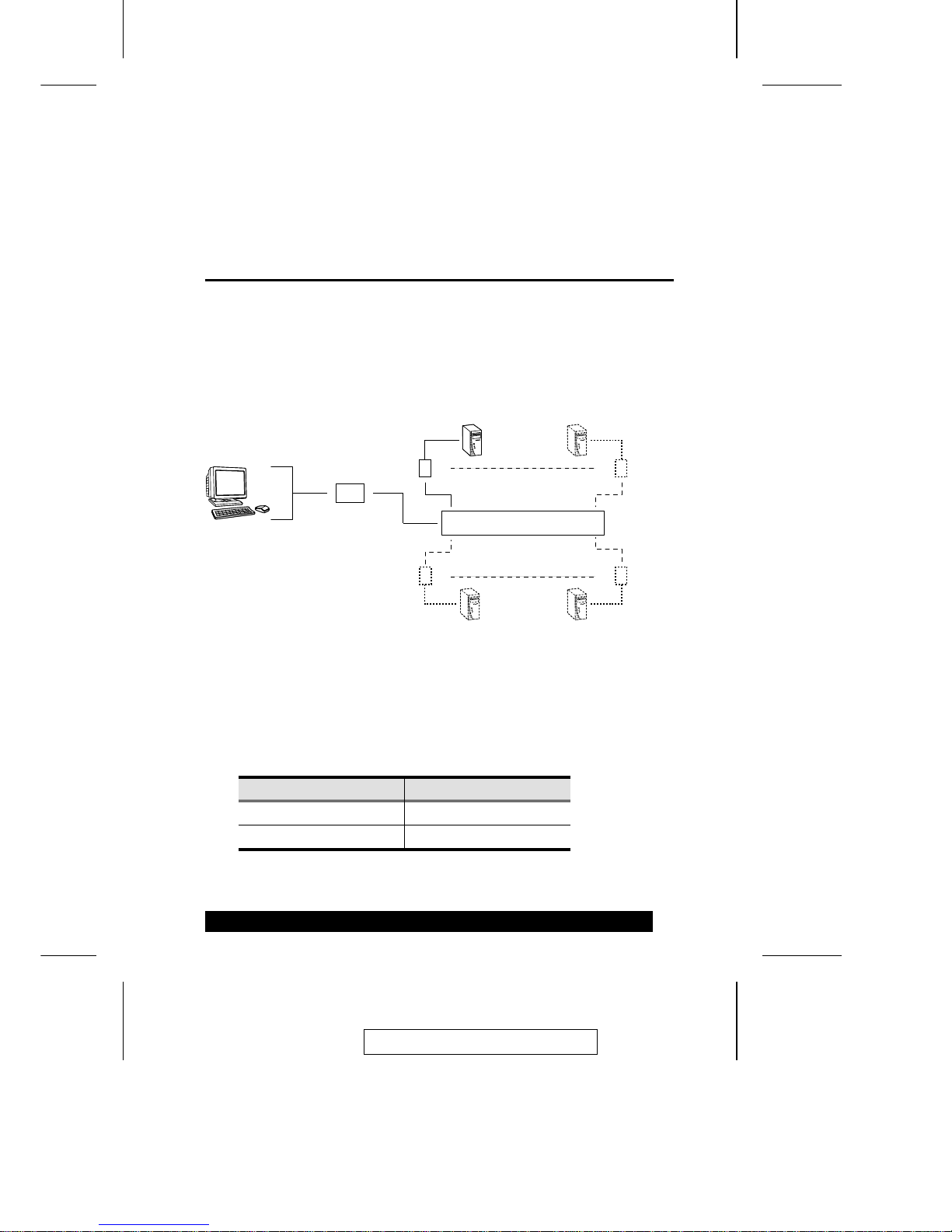
Overview
For convenience and flexibility that allows mixing the PS/2 and USB
interfaces, the KM0432’s design utilizes Console Modules that act as signal
translation intermediaries between the consoles and the switch., and KVM
Adapter Cables, that serve as intermediaries between the switch and the
computers:
A separate console module is required for each console you connect. Likewise,
a separate KVM adapter cable is required for each computer co nnectio n. T h e
console module model number for each interface is shown in the table below.
The model numbers of the KVM adapter cables are given in the Cables section
on p. 4.
Interface Console Model
PS/2 KA9220
USB KA9270
KM0432
KA9220
or
KA9270
KA9120
KA9170
KA9131
KA9130
2003-12-15
11

Before you Begin
Single Stage Installation
In a Single Stage installation, there are no additional KVM switches daisy
chained or cascaded down from the first unit. To set up a single stage
installation, refer to the diagram on p. 14 (the numbers in the diagram
correspond with the numbers of the instruction steps), and do the following:
1. Connnect the Console to the Console Module
Plug your keyboard, mouse, and monitor into their respective ports on the
Console Module. Each port is marked with an icon to indicate itself.
Note: The diagram shows the rear panel of both the KA9220 (PS/2 port)
and KA9720 (USB port) modules.
2. Connect the Console Module to the KM0432
Use Cat. 5 cable to connect the Link port of the module to one of the
Console ports on the KM0432’s rear panel. Up to four consoles can be
connected.
Note: The distance between the Console Module and the KM0432 must
not exceed 150m (500’).
(Repeat Steps 1 and 2 for any other consoles you wish to connect.)
1. Make sure that power to all the devices you will be connecting up
have been turned off. You must unplug the power cords of any
computers that have the Keyboard Power On function.
2. To prevent damage to your installation, make sure that all devices
on the installation are properly grounded.
2003-12-15
12

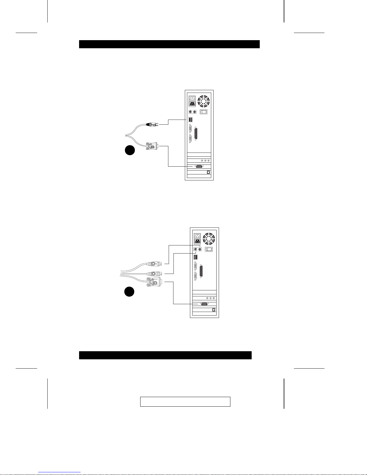
3. Connect the KM0432 to the KVM Adapter Cable
Use Cat. 5 cable to connect any available CPU Port to a KVM adapter cable
that is appropriate for the computer you are installing (see the table on p. 4
for details).
Note: The distance between the KM0432 and the KVM Adapter Cable
must not exceed 150m (500’).
4. Connect the KVM Adapter Cable to the Computer.
Plug the connectors on the KVM cable into the appropriate ports of the
computer you are installing.
Note: Repeat steps 3 and 4 for all the computers you wish to connect. Up
to 32 computers can be connected in this fashion.
5. After all your computers have been cabled up, plug the female end of the
power cord into the KM4032’s Power Socket; plug the male end into an AC
power source.
6. For each Console Module, plug its power adapter into an AC source; plug
the power adapter cable into the unit’s power jack.
7. Turn on the power to the KM0432.
8. Turn on the power to the computers.
2003-12-15
13
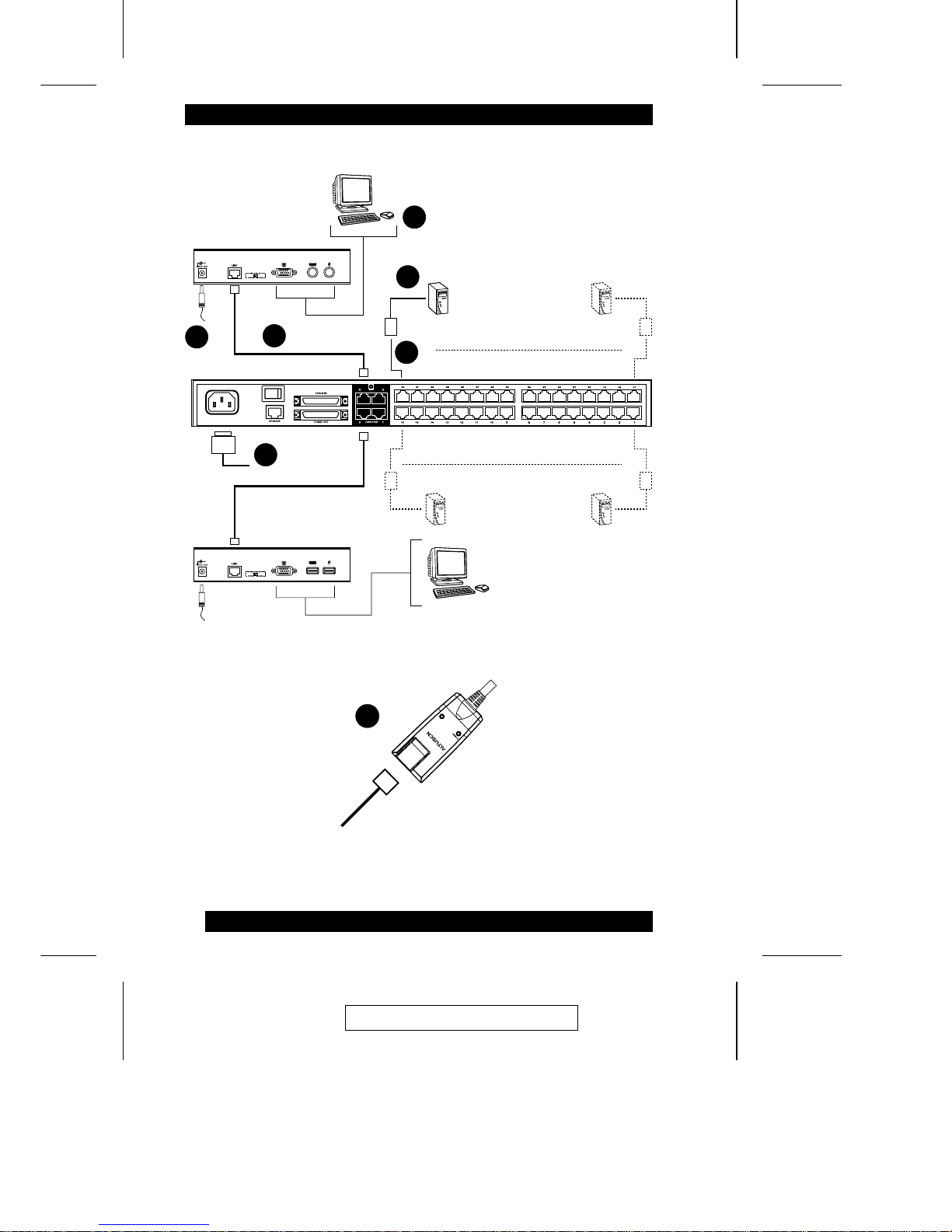
5
6
1
2
3
4
KA9220
KA9270
by A
T
E
N
PS/2 CPU MODUL
E
MODEL
NO. KA9120
PS/2 CPU MODUL
E
MODEL
NO. KA9120
LIN
K
3
2003-12-15
14
4
USB Cable Connection:
4
PS/2 Cable Connection:
2003-12-15
15

Multilevel Installations
The number of computers that can be added to your installation can be greatly
expanded by performing a multilevel installation. The KM0432 supports three
types of multilevel installation:
M Daisy chained
M Cascaded
M Daisy chained plus cascaded
Overview
Daisy chaining refers to connecting two KVM switches via dedicated daisy
chain ports. The switches are strung together in a chain (see the diagram on p.
18), similar to the way children make chains of daisies by tying the head of one
daisy to the end of another - hence the designation.
With daisy chaining none of the switch’s CPU ports are used to connect to the
next switch. The port capacity of a daisy chained installation is the total of all
the CPU ports of all the KVM switches on the chain. For example, a KM0432
has 32 CPU ports. On an installation with eight daisy chained switches the
number of available ports is 32 x 8 = 256.
Cascading involves using the CPU ports of a Parent KVM switch (one that is
above a switch linked down from it) to connect to a Child KVM switch. With
numerous Child switches linked down from the parent, the effect is reminiscen t
of the way water cascades down over a waterfall. Cascading adds capacity to a
KVM installation, but the parent loses one CPU port for each cascaded KVM.
The KM0432 supports both daisy chaining and cascading. In addition, it
supports combining the two - providing enormous capacity and flexibility for
expanding the installation. The following sections provide the information and
proecedures involved in setting up the various multilevel installations .
2003-12-15
16
 Loading...