

© 20 04 A LT US E N. All rights res erved. AL TU S EN is a tra demark of AT EN , I nc. All O ther tradema rks are the property of their res pective owners. P AP E -121 4-701
Matrix K V M S witc h (K M02 16 / K M0432) Q UIC K S TA RT G UIDE
2
Hardware Requirements
C onsole
¥ A V GA , SV GA , or M ultisync monitor capable of the highest resolution that you will be
using on any computer in the installation.
¥ E ither a PS/2 or a USB keyboard and mouse.
C omputers
¥ A n HDB -15 video port or, for legacy Sun systems, a Sun 13W3 vi deo port.
¥ E ither a PS/2 style (6 pin mini-DI N) mouse port and PS/2 style keyboard port; or USB
ports (for a USB keyboard and US B mouse); or, for legacy S un systems, a Sun style key
boardport (8 pin mini-DIN) .
5
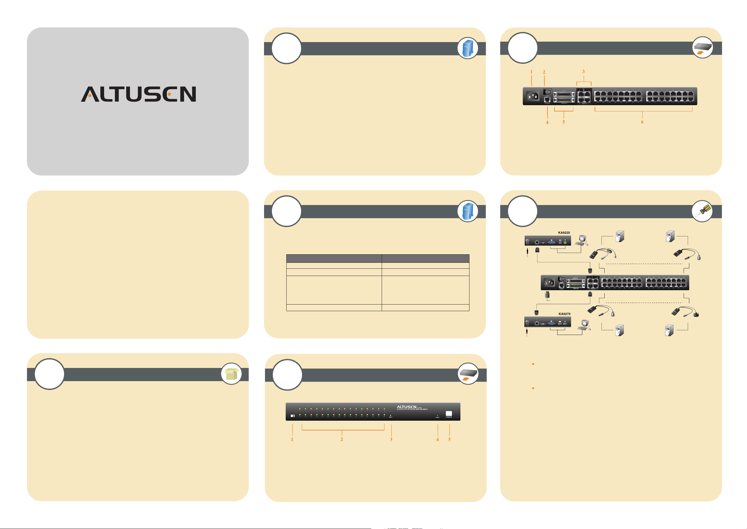
The Matrix KVM Switch Unit ( Rear View )
1. P ower Socket 4. F irmwar e Upgrade Por t
2. P ower Switch 5. D aisy C hain P or ts
3. C onsole P or t S ection 6. C omputer Port Section
* The diagram shows the K M 0432 model. T he K M 0216 only has two console prots and
16 C PU ports *
T hese instr uctions show how to install the K M 0216 /
K M 0432 F or detailed information, r efer to the user
manual included in the kit.
1
Package Contents
3
Hardware Requirements
C ables
F unction C able
Matrix K V M Switch to C onsole M odule C at. 5 cable
Matrix K V M Switch to K V M Adapter C able C at. 5 cable
K V M A dapter Cable For PS/2 ports : K A 9120
(T o computer or cascaded K VM switch)
F or U SB ports : K A 9170
F or Sun L egacy : K A 9130
F or Sun US B : K A9131
Daisy C hain Cable K C1800
4
The Matrix KVM Switch Unit ( Front View )
6
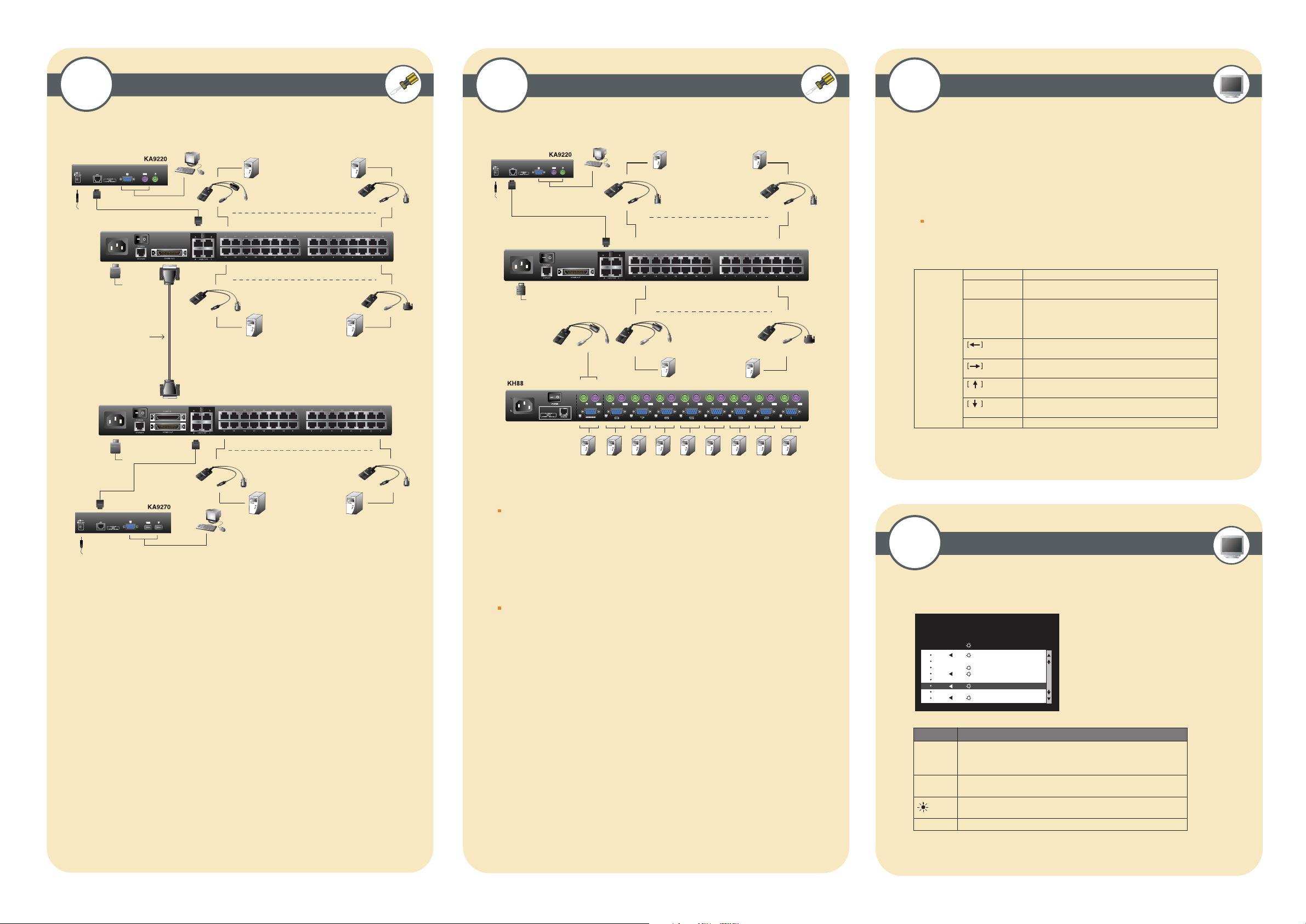
Single Stage Installationtion
PC
K
N
I
L
R
E
W
O
P
K
N
I
L
R
E
W
O
P
KA9120
KA9170 KA9130
Mac
SUN (USB)
SUN
KA9131
K
N
I
L
R
E
1. C onnnect the C onsole to the Console Module
2. C onnect the Console M odule to the Matrix K V M Switch
NOTE : T he distance between the C onsole M odule and the Matrix K V M S witch must
not exceed 150m ( 500').
3. C onnect the Matrix K V M Switch to the K V M A dapter C able
NOTE : T he distance between the M atrix K V M S witch and the K V M Adapter C able
must not exceed 150m (500').
K
N
I
L
R
E
OW
P
W
O
P
T he complete package consists of :
¥ 1 K M0216 / K M0432 Matrix K V M S witch
¥ 1 Power Cord
¥ 1 R ackM ounting K it
¥ 1 User Manual
¥ 1 Quick Start G uide
¥ 1 W arranty R egistration Card
1. F ir mwar e U pgr ade R ecovery Switch
2. P or t L E Ds
3. R eset Switch
4. P ower L E D
5. S tation I D L E D
* The diagram shows the K M 0432 model. T he K M 0216 only has one r ow of L E Ds *
4. C onnect the K VM A dapter Cable to the C omputer.
5. R epeat steps 3 and 4 for all the computers you wish to connect.
6. A fter all your computers have been cabled up, plug the female end of the power
cord into the M atrix K V M Switch Power S ocket; plug the male end into an AC power
source.
7. F or each C onsole Module, plug its power adapter into an AC source; plug the power
adapter cable into the unit's power jack.
8. T urn on the power to the M atrix K V M Switch.
9. T urn on the power to the computers.
7
Daisy Chained Installation
K
N
I
L
R
E
W
O
P
PC
KA9120
SUN (USB)
KA9131
8
Cascaded Installation
9
Invoking Hotkey Mode (HKM)
1. Press and hold down the <Num L ock> key
Mac
K
N
I
K
N
I
L
R
E
W
O
P
L
R
E
W
O
P
KA9170
SUN (USB)
KA9131
K
N
I
L
R
E
W
O
P
3. R elease the <Num L ock> key
2. Press and release the <minus> key
NOTE : The minus key must be released within one half second, otherwise the hotkey
operation is canceled
K
N
I
L
R
E
W
O
Daisy Chain Cable
P
K
N
I
L
R
E
W
O
P
KA9170
KA9170
KA9130
SUN Mac
KA9130
SUN Mac
1. M ake sure that power to all the devices you will be connecting up has been turned off.
2. U se a daisy chain cable set to connect the C hain Out port of the parent M atrix K V M
S witch unit to the Chain In port of the child Matrix K V M Switch unit.
3. I f you wish to install any consoles on this switch, follow the procedure described for
the S ingle Stage I nstallation.
4. U se K V M A dapter cables to connect any available CPU Port on the M atrix K V M
S witch to the K eyboard, V ideo and Mouse ports of the computers you are i nstalling
5. R epeat the above steps for any additional Matrix K V M Switch units you wish to add
to the chain.
[Port I D] [E nter]
[T ] [n] [Enter]
K
N
I
L
R
E
W
O
P
[A ]
Switches access to the computer that corresponds to that Port ID .
Sets the A uto Scan interval to n seconds - where n is a number
from 1 - 255.I nvokes A uto Scan Mode.
When Auto Scan Mode i s in effect, [P] or L eft Cl ick pauses
A uto Scanning.
K
N
I
L
R
E
W
O
P
[Num Lock]
KA9120
K
N
I
K
N
I
L
ER
W
PO
L
ER
W
PO
KA9120
KA9130
+ [-]
PC
!
SUN
When Auto Scanning is paused, pressing A ny Key or another
L eft C lick resumes A uto Scanning.
Invokes Sk ip M ode and Sk ips f rom the current port to the f irst
accessible port previous to i t.
Invokes Sk ip M ode and Sk ips f rom the current port to the next
accessible port.
Invokes Sk ip M ode and Sk ips f rom the current port to the l ast
accessible port of the previous Station.
Invokes Sk ip M ode and Sk ips f rom the current port to the f irst
accessible port of the next Station.
[B ]
K
N
I
L
R
E
W
O
P
T oggles the Beeper On or Of f.
Up to 32 additional K V M switches can be cascaded from the K M0432's CPU ports.
NOTE : Matrix K V M S witch's cannot be cascaded. Y ou must use the A ltusen K H88 or
K H0116 cascading
1. M ake sure that power to all the devices you will be connecting up has been turned off.
10
OSD Main Screen Headings
2. U se C at 5 cable to connect any available CPU Port on the First Stage unit (the K M0432) to
a PS/2 styl e K V M adapter cable; plug the adapter cable's K V M connectors to the K eyboard,
V ideo, and M ouse C onsole ports of the Second Stage unit.
* A ctivate OS D, pr ess [ Scroll L ock] [S croll L ock] or [C trl] [C trl ] *
NOTE : The distance between the S econd Stage unit and the Matrix K V M Switch must not
exceed 150m ( 500')
3. Plug the Second Stage unit's power adapter into an AC source; plug the power adapter
cable into the unit's Power S ocket.
4. C onnect the K VM converter (K A9120) with the console on the second level K V M.
T hen use CA T5 cable to connect the K V M converter to the C PU side of the Matrix K V M.
F 1 : G O T O F 3 : S E T F 5 : S K P F 7 : S C A N X
F 2 : L I S T F 4 : A D M F 6 : B R C F 8 : L O U T z
S U P E R A D M I N I S T R A T O R S N : 0 2 / 0 8
LI ST : AL L
PN QV NAM E
01 AT E N I NTL .C O . 1
02 AT E N I NTL .C O . 2
03 AT E N I NTL .C O . 3
06 FA X SE R VE R 1
05 FA X SE R VE R 2
06 3 WE B S E R VE R 1
07 4 WE B S E R VE R 2
08 5 MAI L S ER V E R 1
z
z
5. R epeat steps 3 Ð 4 for any other Second Stage units you wish to connect
6. T urn on the power for the Fi rst Stage unit.
H eading
PN
QV
NA ME
This column lists the Port ID numbers (Station N umber - Port Number)
for all the C PU ports on the installation. T he simplest method to access
a particular computer is move the Highlight B ar to i t, then press E nter.
If a port has selected for Quick V iew scanning an arrowhead displays
in this column to indicate so.
The computers that are powered on and are On L ine have a Sun symbol
in this column to indicate so.
If a port has been given a name, its name appears in this column.
E xplanation
 Loading...