

5/9 Console 32-Port Matrix KVM Switch
KM0532 / KM0932
Matrix Expansion KVM Switch
KM0032
User Manual
www.aten.com
KM0032 / KM0532 / KM0932 User Manual
FCC, CE Information
FEDERAL COMMUNICATIONS COMMISSION INTERFERENCE
STATEMENT: This equipment has been tested and found to comply with the
limits for a Class A digital device, pursuant to Part 15 of the FCC Rules. These
limits are designed to provide reasonable protection against harmful
interference when the equipment is operated in a commercial environment.
This equipment generates, uses, and can radiate radio frequency energy and, if
not installed and used in accordance with the instruction manual, may cause
harmful interference to radio communications. Operation of this equipment in
a residential area is likely to cause harmful interference in which case the user
will be required to correct the interference at his own expense.
FCC Caution: Any changes or modifications not expressly approved by the
party responsible for compliance could void the user's authority to operate this
equipment.
CE Warning: This is a class A product. In a domestic environment this product
may cause radio interference in which case the user may be required to take
adequate measures.
RoHS
This product is RoHS compliant.
SJ/T 11364-2006
The following contains information that relates to China.
ii
KM0032 / KM0532 / KM0932 User Manual
User Information
Online Registration
Be sure to register your product at our online support center:
International http://eservice.aten.com
Telephone Support
For telephone support, call this number:
International 886-2-8692-6959
China 86-10-5255-0110
Japan 81-3-5615-5811
Korea 82-2-467-6789
North America 1-888-999-ATEN ext 4988
United Kingdom 44-8-4481-58923
User Notice
All information, documentation, and specifications contained in this manual
are subject to change without prior notification by the manufacturer. The
manufacturer makes no representations or warranties, either expressed or
implied, with respect to the contents hereof and specifically disclaims any
warranties as to merchantability or fitness for any particular purpose. Any of
the manufacturer's software described in this manual is sold or licensed as is.
Should the programs prove defective following their purchase, the buyer (and
not the manufacturer, its distributor, or its dealer), assumes the entire cost of all
necessary servicing, repair and any incidental or consequential damages
resulting from any defect in the software.
The manufacturer of this system is not responsible for any radio and/or TV
interference caused by unauthorized modifications to this device. It is the
responsibility of the user to correct such interference.
The manufacturer is not responsible for any damage incurred in the operation
of this system if the correct operational voltage setting was not selected prior
to operation. PLEASE VERIFY THAT THE VOLTAGE SETTING IS
CORRECT BEFORE USE.
iii

KM0032 / KM0532 / KM0932 User Manual
Copyright © 2013 ATEN® International Co., Ltd.
Manual Part No. PAPE-0308-AX3G
F/W Version: 2.0.191
Manual Date: 2013-10-31
Altusen and the Altusen logo are registered trademarks of ATEN International Co., Ltd. All rights reserved.
All other brand names and trademarks are the registered property of their respective owners.
Package Contents
The KM0032 / KM0532 / KM0932 package consists of:
1 KM0032, KM0532, or KM0932
2Power Cords
1 Daisy Chain Cable (KM0032 only)
1 Mounting Kit
1 User Instructions*
Check to make sure that all of the components are present and in good order.
If anything is missing, or was damaged in shipping, contact your dealer.
Read this manual thoroughly and follow the installation and operation
procedures carefully to prevent any damage to the switch or to any other
devices on the KM0032 / KM0532 / KM0932 installation.
* Features may have been added to the switch since this manual was published.
Please visit our website to download the most up to date version of the
manual.
iv

KM0032 / KM0532 / KM0932 User Manual
Contents
FCC, CE Information . . . . . . . . . . . . . . . . . . . . . . . . . . . . . . . . . . . . . . . . . ii
SJ/T 11364-2006. . . . . . . . . . . . . . . . . . . . . . . . . . . . . . . . . . . . . . . . . . . . . ii
User Information . . . . . . . . . . . . . . . . . . . . . . . . . . . . . . . . . . . . . . . . . . . . .iii
Online Registration . . . . . . . . . . . . . . . . . . . . . . . . . . . . . . . . . . . . . . . .iii
Telephone Support . . . . . . . . . . . . . . . . . . . . . . . . . . . . . . . . . . . . . . . .iii
User Notice . . . . . . . . . . . . . . . . . . . . . . . . . . . . . . . . . . . . . . . . . . . . . .iii
Package Contents . . . . . . . . . . . . . . . . . . . . . . . . . . . . . . . . . . . . . . . . . . iv
About This Manual . . . . . . . . . . . . . . . . . . . . . . . . . . . . . . . . . . . . . . . . . . xi
Overview . . . . . . . . . . . . . . . . . . . . . . . . . . . . . . . . . . . . . . . . . . . . . . . xi
Conventions . . . . . . . . . . . . . . . . . . . . . . . . . . . . . . . . . . . . . . . . . . . .xiii
Product Information. . . . . . . . . . . . . . . . . . . . . . . . . . . . . . . . . . . . . . . . . .xiii
Chapter 1.
Introduction
Overview . . . . . . . . . . . . . . . . . . . . . . . . . . . . . . . . . . . . . . . . . . . . . . . . . . .1
Features . . . . . . . . . . . . . . . . . . . . . . . . . . . . . . . . . . . . . . . . . . . . . . . . . . .2
Requirements . . . . . . . . . . . . . . . . . . . . . . . . . . . . . . . . . . . . . . . . . . . . . . . 5
Consoles . . . . . . . . . . . . . . . . . . . . . . . . . . . . . . . . . . . . . . . . . . . . . . . 5
Computers. . . . . . . . . . . . . . . . . . . . . . . . . . . . . . . . . . . . . . . . . . . . . . .5
Cables . . . . . . . . . . . . . . . . . . . . . . . . . . . . . . . . . . . . . . . . . . . . . . . . .6
KVM Adapter Cables . . . . . . . . . . . . . . . . . . . . . . . . . . . . . . . . . . . . . . . . .6
Connecting Cables . . . . . . . . . . . . . . . . . . . . . . . . . . . . . . . . . . . . . 6
Operating Systems . . . . . . . . . . . . . . . . . . . . . . . . . . . . . . . . . . . . . . . . 7
Components . . . . . . . . . . . . . . . . . . . . . . . . . . . . . . . . . . . . . . . . . . . . . . . . 8
KM0532 / KM0932 Front View . . . . . . . . . . . . . . . . . . . . . . . . . . . . . . .8
KM0032 Front View . . . . . . . . . . . . . . . . . . . . . . . . . . . . . . . . . . . . . . . . .10
KM0532 / KM0932 Rear View . . . . . . . . . . . . . . . . . . . . . . . . . . . . . . . . . 11
KM0032 Rear View . . . . . . . . . . . . . . . . . . . . . . . . . . . . . . . . . . . . . . . . .12
Chapter 2.
Hardware Setup
Overview . . . . . . . . . . . . . . . . . . . . . . . . . . . . . . . . . . . . . . . . . . . . . . . . . .13
Stacking. . . . . . . . . . . . . . . . . . . . . . . . . . . . . . . . . . . . . . . . . . . . . . . .14
Rack Mounting . . . . . . . . . . . . . . . . . . . . . . . . . . . . . . . . . . . . . . . . . .15
Rack Mounting - Front . . . . . . . . . . . . . . . . . . . . . . . . . . . . . . . . . . 15
Rack Mounting - Rear . . . . . . . . . . . . . . . . . . . . . . . . . . . . . . . . . .17
Grounding . . . . . . . . . . . . . . . . . . . . . . . . . . . . . . . . . . . . . . . . . . . . . . . .19
Single Level Installation . . . . . . . . . . . . . . . . . . . . . . . . . . . . . . . . . . . . . .20
Multilevel Installations . . . . . . . . . . . . . . . . . . . . . . . . . . . . . . . . . . . . . . .22
Overview . . . . . . . . . . . . . . . . . . . . . . . . . . . . . . . . . . . . . . . . . . . . . . 22
Cascading . . . . . . . . . . . . . . . . . . . . . . . . . . . . . . . . . . . . . . . . . . . . . 23
Cascading KM0532 / KM0932 Switches . . . . . . . . . . . . . . . . . . . . 24
Cascading Other KVM Switches . . . . . . . . . . . . . . . . . . . . . . . . . .26
Daisy Chaining . . . . . . . . . . . . . . . . . . . . . . . . . . . . . . . . . . . . . . . . . .27
v

KM0032 / KM0532 / KM0932 User Manual
Network Administration. . . . . . . . . . . . . . . . . . . . . . . . . . . . . . . . . . . . . . . 28
Topology Considerations . . . . . . . . . . . . . . . . . . . . . . . . . . . . . . . . . . . . . 28
The Adapter ID Function . . . . . . . . . . . . . . . . . . . . . . . . . . . . . . . . . . . 29
Chapter 3.
Super Administrator Setup
Overview. . . . . . . . . . . . . . . . . . . . . . . . . . . . . . . . . . . . . . . . . . . . . . . . . . 31
First Time Setup . . . . . . . . . . . . . . . . . . . . . . . . . . . . . . . . . . . . . . . . . . . . 31
Network Configuration . . . . . . . . . . . . . . . . . . . . . . . . . . . . . . . . . . . . 33
Changing the Super Administrator Login . . . . . . . . . . . . . . . . . . . . . . 34
Moving On . . . . . . . . . . . . . . . . . . . . . . . . . . . . . . . . . . . . . . . . . . . . . . . . 35
Chapter 4.
Logging In
Overview. . . . . . . . . . . . . . . . . . . . . . . . . . . . . . . . . . . . . . . . . . . . . . . . . . 37
Console Login. . . . . . . . . . . . . . . . . . . . . . . . . . . . . . . . . . . . . . . . . . . . . . 37
Browser Login . . . . . . . . . . . . . . . . . . . . . . . . . . . . . . . . . . . . . . . . . . . . . 38
Disable OSD Login Mode . . . . . . . . . . . . . . . . . . . . . . . . . . . . . . . . . . . . . 38
Chapter 5.
The User Interface
The Console UI. . . . . . . . . . . . . . . . . . . . . . . . . . . . . . . . . . . . . . . . . . . . . 39
Console UI Page Components . . . . . . . . . . . . . . . . . . . . . . . . . . . . . . 40
Console UI Keyboard Navigation . . . . . . . . . . . . . . . . . . . . . . . . . . . . 41
The Browser UI . . . . . . . . . . . . . . . . . . . . . . . . . . . . . . . . . . . . . . . . . . . . 42
Browser UI Page Components . . . . . . . . . . . . . . . . . . . . . . . . . . . . . . 43
Chapter 6.
Device Management
Overview. . . . . . . . . . . . . . . . . . . . . . . . . . . . . . . . . . . . . . . . . . . . . . . . . . 45
Device. . . . . . . . . . . . . . . . . . . . . . . . . . . . . . . . . . . . . . . . . . . . . . . . . . . . 45
Dual Root . . . . . . . . . . . . . . . . . . . . . . . . . . . . . . . . . . . . . . . . . . . . . . . . . 48
Dual Root Cascading . . . . . . . . . . . . . . . . . . . . . . . . . . . . . . . . . . . . . 50
KA7178 Dual Output Dongle . . . . . . . . . . . . . . . . . . . . . . . . . . . . . . . . . . 53
Network . . . . . . . . . . . . . . . . . . . . . . . . . . . . . . . . . . . . . . . . . . . . . . . . . . 54
IP Installer . . . . . . . . . . . . . . . . . . . . . . . . . . . . . . . . . . . . . . . . . . . . . 56
Service Ports . . . . . . . . . . . . . . . . . . . . . . . . . . . . . . . . . . . . . . . . . 56
IP Address. . . . . . . . . . . . . . . . . . . . . . . . . . . . . . . . . . . . . . . . . . . 56
DNS Server . . . . . . . . . . . . . . . . . . . . . . . . . . . . . . . . . . . . . . . . . . 57
ANMS . . . . . . . . . . . . . . . . . . . . . . . . . . . . . . . . . . . . . . . . . . . . . . . . . . . 58
SMTP Settings . . . . . . . . . . . . . . . . . . . . . . . . . . . . . . . . . . . . . . . . . . 60
Association . . . . . . . . . . . . . . . . . . . . . . . . . . . . . . . . . . . . . . . . . . . . . . . 64
Power Management . . . . . . . . . . . . . . . . . . . . . . . . . . . . . . . . . . . . . . 64
Summary . . . . . . . . . . . . . . . . . . . . . . . . . . . . . . . . . . . . . . . . . . . . . . 70
MultiView . . . . . . . . . . . . . . . . . . . . . . . . . . . . . . . . . . . . . . . . . . . . . . . . . 71
MultiView Groups . . . . . . . . . . . . . . . . . . . . . . . . . . . . . . . . . . . . . . . . 72
vi

KM0032 / KM0532 / KM0932 User Manual
Creating IO Groups . . . . . . . . . . . . . . . . . . . . . . . . . . . . . . . . . . . . 72
Creating Console Groups . . . . . . . . . . . . . . . . . . . . . . . . . . . . . . .73
Security . . . . . . . . . . . . . . . . . . . . . . . . . . . . . . . . . . . . . . . . . . . . . . . . . . 75
Date/Time . . . . . . . . . . . . . . . . . . . . . . . . . . . . . . . . . . . . . . . . . . . . . . . . . 78
Date. . . . . . . . . . . . . . . . . . . . . . . . . . . . . . . . . . . . . . . . . . . . . . . . . . .78
Time . . . . . . . . . . . . . . . . . . . . . . . . . . . . . . . . . . . . . . . . . . . . . . . . . .78
Time Zone . . . . . . . . . . . . . . . . . . . . . . . . . . . . . . . . . . . . . . . . . . . . .78
Current System Time. . . . . . . . . . . . . . . . . . . . . . . . . . . . . . . . . . . 79
Time Zone . . . . . . . . . . . . . . . . . . . . . . . . . . . . . . . . . . . . . . . . . . .80
System . . . . . . . . . . . . . . . . . . . . . . . . . . . . . . . . . . . . . . . . . . . . . . . . . . .81
Chapter 7.
User Management
Overview . . . . . . . . . . . . . . . . . . . . . . . . . . . . . . . . . . . . . . . . . . . . . . . . . .83
Accounts . . . . . . . . . . . . . . . . . . . . . . . . . . . . . . . . . . . . . . . . . . . . . . . . . .83
Adding Users. . . . . . . . . . . . . . . . . . . . . . . . . . . . . . . . . . . . . . . . . . . . 85
Modifying User Accounts . . . . . . . . . . . . . . . . . . . . . . . . . . . . . . . . . .89
Deleting User Accounts . . . . . . . . . . . . . . . . . . . . . . . . . . . . . . . . . . .89
Groups . . . . . . . . . . . . . . . . . . . . . . . . . . . . . . . . . . . . . . . . . . . . . . . . . . .90
Creating Groups . . . . . . . . . . . . . . . . . . . . . . . . . . . . . . . . . . . . . . . . .90
Modifying Groups . . . . . . . . . . . . . . . . . . . . . . . . . . . . . . . . . . . . . . . . 92
Deleting Groups . . . . . . . . . . . . . . . . . . . . . . . . . . . . . . . . . . . . . . . . .92
Users and Groups . . . . . . . . . . . . . . . . . . . . . . . . . . . . . . . . . . . . . . . . . .93
Assigning Users to a Group From the User Menu . . . . . . . . . . . . . . .93
Removing Users From a Group From the User Menu . . . . . . . . . . . . 94
Assigning Users to a Group From the Group Menu . . . . . . . . . . . . . .97
Removing Users From a Group From the Group Menu . . . . . . . . . . . 99
Device Assignment . . . . . . . . . . . . . . . . . . . . . . . . . . . . . . . . . . . . . . . . 101
Assigning Device Permissions From the User Menu . . . . . . . . . . . .101
Assigning Device Permissions From the Group Menu . . . . . . . . . . .103
Chapter 8.
Port Access
Overview . . . . . . . . . . . . . . . . . . . . . . . . . . . . . . . . . . . . . . . . . . . . . . . . . 105
Page Layout . . . . . . . . . . . . . . . . . . . . . . . . . . . . . . . . . . . . . . . . . . .107
The Port Selection Sidebar . . . . . . . . . . . . . . . . . . . . . . . . . . . . . . . . . . . 107
The Port Selection Tree . . . . . . . . . . . . . . . . . . . . . . . . . . . . . . . . . .107
Show . . . . . . . . . . . . . . . . . . . . . . . . . . . . . . . . . . . . . . . . . . . . . . . . 109
Connections . . . . . . . . . . . . . . . . . . . . . . . . . . . . . . . . . . . . . . . . . . . . . .110
Device Level . . . . . . . . . . . . . . . . . . . . . . . . . . . . . . . . . . . . . . . . . . . 110
Port Level . . . . . . . . . . . . . . . . . . . . . . . . . . . . . . . . . . . . . . . . . . . . .112
Associated Link . . . . . . . . . . . . . . . . . . . . . . . . . . . . . . . . . . . . . .113
Console Selector . . . . . . . . . . . . . . . . . . . . . . . . . . . . . . . . . . . . . . . . . .114
Favorites . . . . . . . . . . . . . . . . . . . . . . . . . . . . . . . . . . . . . . . . . . . . . . . .116
Adding a Favorite . . . . . . . . . . . . . . . . . . . . . . . . . . . . . . . . . . . . . . .117
Removing a Favorite . . . . . . . . . . . . . . . . . . . . . . . . . . . . . . . . . . . . .117
vii

KM0032 / KM0532 / KM0932 User Manual
History. . . . . . . . . . . . . . . . . . . . . . . . . . . . . . . . . . . . . . . . . . . . . . . . . . . 117
Preferences . . . . . . . . . . . . . . . . . . . . . . . . . . . . . . . . . . . . . . . . . . . . . . 119
Changing the Preference Settings . . . . . . . . . . . . . . . . . . . . . . . . . . 121
Multicast Audio . . . . . . . . . . . . . . . . . . . . . . . . . . . . . . . . . . . . . . . . . 123
Restore Defaults . . . . . . . . . . . . . . . . . . . . . . . . . . . . . . . . . . . . . . . . 123
Sessions . . . . . . . . . . . . . . . . . . . . . . . . . . . . . . . . . . . . . . . . . . . . . . . . 124
Kill Session . . . . . . . . . . . . . . . . . . . . . . . . . . . . . . . . . . . . . . . . . . . . 125
Scan . . . . . . . . . . . . . . . . . . . . . . . . . . . . . . . . . . . . . . . . . . . . . . . . . . . . 125
Broadcast . . . . . . . . . . . . . . . . . . . . . . . . . . . . . . . . . . . . . . . . . . . . . . . . 125
Access . . . . . . . . . . . . . . . . . . . . . . . . . . . . . . . . . . . . . . . . . . . . . . . . . . 127
Properties . . . . . . . . . . . . . . . . . . . . . . . . . . . . . . . . . . . . . . . . . . . . . . . 129
Configuring Port Properties . . . . . . . . . . . . . . . . . . . . . . . . . . . . . . . 129
KA7140 Properties . . . . . . . . . . . . . . . . . . . . . . . . . . . . . . . . . . . . . . 133
Restore Defaults . . . . . . . . . . . . . . . . . . . . . . . . . . . . . . . . . . . . . . . 134
PON . . . . . . . . . . . . . . . . . . . . . . . . . . . . . . . . . . . . . . . . . . . . . . . . . . . . 135
Chapter 9.
Console Port Operation
Overview. . . . . . . . . . . . . . . . . . . . . . . . . . . . . . . . . . . . . . . . . . . . . . . . . 137
The Port Toolbar . . . . . . . . . . . . . . . . . . . . . . . . . . . . . . . . . . . . . . . . . . 138
Recalling the Port Access Page . . . . . . . . . . . . . . . . . . . . . . . . . . . . 138
Closing the Toolbar. . . . . . . . . . . . . . . . . . . . . . . . . . . . . . . . . . . . . . 138
The Toolbar Icons . . . . . . . . . . . . . . . . . . . . . . . . . . . . . . . . . . . . . . 139
Toolbar Hotkey Port Switching . . . . . . . . . . . . . . . . . . . . . . . . . . . . . 140
Auto Scanning . . . . . . . . . . . . . . . . . . . . . . . . . . . . . . . . . . . . . . . 140
Skip Mode Switching . . . . . . . . . . . . . . . . . . . . . . . . . . . . . . . . . . 141
Port Number Switching . . . . . . . . . . . . . . . . . . . . . . . . . . . . . . . . 141
Keyboard Hotkey Port Switching . . . . . . . . . . . . . . . . . . . . . . . . . . . . . . 142
Port ID Numbering . . . . . . . . . . . . . . . . . . . . . . . . . . . . . . . . . . . . . . 142
Push Video Hotkey . . . . . . . . . . . . . . . . . . . . . . . . . . . . . . . . . . . . . . . . 143
Operation Mode . . . . . . . . . . . . . . . . . . . . . . . . . . . . . . . . . . . . . . . . 143
Hotkey Summary Table . . . . . . . . . . . . . . . . . . . . . . . . . . . . . . . . . . . . . 144
Chapter 10.
Log
Overview. . . . . . . . . . . . . . . . . . . . . . . . . . . . . . . . . . . . . . . . . . . . . . . . . 145
Console UI . . . . . . . . . . . . . . . . . . . . . . . . . . . . . . . . . . . . . . . . . . . . . . . 146
Log Filtering . . . . . . . . . . . . . . . . . . . . . . . . . . . . . . . . . . . . . . . . . . . 146
Browser UI . . . . . . . . . . . . . . . . . . . . . . . . . . . . . . . . . . . . . . . . . . . . . . . 148
Log Filtering . . . . . . . . . . . . . . . . . . . . . . . . . . . . . . . . . . . . . . . . . . . 148
Export . . . . . . . . . . . . . . . . . . . . . . . . . . . . . . . . . . . . . . . . . . . . . . . . 148
Chapter 11.
The Log Server
Installation. . . . . . . . . . . . . . . . . . . . . . . . . . . . . . . . . . . . . . . . . . . . . . . . 149
Starting Up . . . . . . . . . . . . . . . . . . . . . . . . . . . . . . . . . . . . . . . . . . . . . . . 150
viii

KM0032 / KM0532 / KM0932 User Manual
The Menu Bar . . . . . . . . . . . . . . . . . . . . . . . . . . . . . . . . . . . . . . . . . . . .151
Configure . . . . . . . . . . . . . . . . . . . . . . . . . . . . . . . . . . . . . . . . . . . . . 151
Events . . . . . . . . . . . . . . . . . . . . . . . . . . . . . . . . . . . . . . . . . . . . . . . 152
Search: . . . . . . . . . . . . . . . . . . . . . . . . . . . . . . . . . . . . . . . . . . . . 152
Maintenance: . . . . . . . . . . . . . . . . . . . . . . . . . . . . . . . . . . . . . . . .153
Options . . . . . . . . . . . . . . . . . . . . . . . . . . . . . . . . . . . . . . . . . . . . . . . 154
Help . . . . . . . . . . . . . . . . . . . . . . . . . . . . . . . . . . . . . . . . . . . . . . . . .154
The Log Server Main Screen . . . . . . . . . . . . . . . . . . . . . . . . . . . . . . . . . 155
Overview . . . . . . . . . . . . . . . . . . . . . . . . . . . . . . . . . . . . . . . . . . . . .155
The List Panel . . . . . . . . . . . . . . . . . . . . . . . . . . . . . . . . . . . . . . . . . 156
The Event Panel . . . . . . . . . . . . . . . . . . . . . . . . . . . . . . . . . . . . . . . . 156
Chapter 12.
Maintenance
Overview . . . . . . . . . . . . . . . . . . . . . . . . . . . . . . . . . . . . . . . . . . . . . . . . . 157
Browser UI . . . . . . . . . . . . . . . . . . . . . . . . . . . . . . . . . . . . . . . . . . . . . . .157
Backup / Restore . . . . . . . . . . . . . . . . . . . . . . . . . . . . . . . . . . . . . . .157
Backup . . . . . . . . . . . . . . . . . . . . . . . . . . . . . . . . . . . . . . . . . . . . . . . 158
Restore . . . . . . . . . . . . . . . . . . . . . . . . . . . . . . . . . . . . . . . . . . . . . . .159
Firmware Upgrade . . . . . . . . . . . . . . . . . . . . . . . . . . . . . . . . . . . . . . . . . 160
Firmware Upgrade Recovery . . . . . . . . . . . . . . . . . . . . . . . . . . . . . . . . . 162
Adapter Cable Firmware Upgrade Recovery . . . . . . . . . . . . . . . . . . . . . 162
Certificates . . . . . . . . . . . . . . . . . . . . . . . . . . . . . . . . . . . . . . . . . . . . . . .163
Private Certificate . . . . . . . . . . . . . . . . . . . . . . . . . . . . . . . . . . . .163
Console UI . . . . . . . . . . . . . . . . . . . . . . . . . . . . . . . . . . . . . . . . . . . . . . .165
EDID Information/Update . . . . . . . . . . . . . . . . . . . . . . . . . . . . . . . . .165
Chapter 13.
RS-232 Port Operation
Overview . . . . . . . . . . . . . . . . . . . . . . . . . . . . . . . . . . . . . . . . . . . . . . . . . 167
Preparation . . . . . . . . . . . . . . . . . . . . . . . . . . . . . . . . . . . . . . . . . . . . . . .167
Connecting . . . . . . . . . . . . . . . . . . . . . . . . . . . . . . . . . . . . . . . . . . . . . . . 168
Restrictions . . . . . . . . . . . . . . . . . . . . . . . . . . . . . . . . . . . . . . . . . . . . . .169
Command Summary . . . . . . . . . . . . . . . . . . . . . . . . . . . . . . . . . . . . . . .170
AS . . . . . . . . . . . . . . . . . . . . . . . . . . . . . . . . . . . . . . . . . . . . . . . . . . .172
Example 1 – Normal Scan: . . . . . . . . . . . . . . . . . . . . . . . . . . . . .172
Example 2 – Specific Scan: . . . . . . . . . . . . . . . . . . . . . . . . . . . . .172
ST . . . . . . . . . . . . . . . . . . . . . . . . . . . . . . . . . . . . . . . . . . . . . . . . . . .172
SP . . . . . . . . . . . . . . . . . . . . . . . . . . . . . . . . . . . . . . . . . . . . . . . . . . .173
Example 1 – Single Stage Installation: . . . . . . . . . . . . . . . . . . . . 173
Example 2 – Two Level Cascaded Installation: . . . . . . . . . . . . . . 173
TK . . . . . . . . . . . . . . . . . . . . . . . . . . . . . . . . . . . . . . . . . . . . . . . . . . .174
TS . . . . . . . . . . . . . . . . . . . . . . . . . . . . . . . . . . . . . . . . . . . . . . . . . . .174
LP . . . . . . . . . . . . . . . . . . . . . . . . . . . . . . . . . . . . . . . . . . . . . . . . . . .175
LI . . . . . . . . . . . . . . . . . . . . . . . . . . . . . . . . . . . . . . . . . . . . . . . . . . .176
SN . . . . . . . . . . . . . . . . . . . . . . . . . . . . . . . . . . . . . . . . . . . . . . . . . . .176
ix

KM0032 / KM0532 / KM0932 User Manual
LU . . . . . . . . . . . . . . . . . . . . . . . . . . . . . . . . . . . . . . . . . . . . . . . . . . . 177
Response Messages . . . . . . . . . . . . . . . . . . . . . . . . . . . . . . . . . . . . 178
Appendix
Safety Instructions . . . . . . . . . . . . . . . . . . . . . . . . . . . . . . . . . . . . . . . . . 179
General . . . . . . . . . . . . . . . . . . . . . . . . . . . . . . . . . . . . . . . . . . . . . . 179
Rack Mounting . . . . . . . . . . . . . . . . . . . . . . . . . . . . . . . . . . . . . . . . . 181
Technical Support . . . . . . . . . . . . . . . . . . . . . . . . . . . . . . . . . . . . . . . . . 182
International . . . . . . . . . . . . . . . . . . . . . . . . . . . . . . . . . . . . . . . . . . . 182
North America . . . . . . . . . . . . . . . . . . . . . . . . . . . . . . . . . . . . . . . . . 182
Trusted Certificates . . . . . . . . . . . . . . . . . . . . . . . . . . . . . . . . . . . . . . . . 183
Overview . . . . . . . . . . . . . . . . . . . . . . . . . . . . . . . . . . . . . . . . . . . . . 183
Self-Signed Private Certificates . . . . . . . . . . . . . . . . . . . . . . . . . . . . . . . 184
Examples . . . . . . . . . . . . . . . . . . . . . . . . . . . . . . . . . . . . . . . . . . . . . 184
Importing the Files . . . . . . . . . . . . . . . . . . . . . . . . . . . . . . . . . . . . . . 184
IP Address Determination . . . . . . . . . . . . . . . . . . . . . . . . . . . . . . . . . . . 185
The Local Console . . . . . . . . . . . . . . . . . . . . . . . . . . . . . . . . . . . . . . 185
IP Installer . . . . . . . . . . . . . . . . . . . . . . . . . . . . . . . . . . . . . . . . . . . . 185
Browser . . . . . . . . . . . . . . . . . . . . . . . . . . . . . . . . . . . . . . . . . . . . . . 186
Troubleshooting . . . . . . . . . . . . . . . . . . . . . . . . . . . . . . . . . . . . . . . . . . . 187
Overview . . . . . . . . . . . . . . . . . . . . . . . . . . . . . . . . . . . . . . . . . . . . . 187
Sun Systems . . . . . . . . . . . . . . . . . . . . . . . . . . . . . . . . . . . . . . . . . . 189
Supported KVM Switches . . . . . . . . . . . . . . . . . . . . . . . . . . . . . . . . . . . 190
Additional Connection Diagrams . . . . . . . . . . . . . . . . . . . . . . . . . . . . . . 191
Console Modules . . . . . . . . . . . . . . . . . . . . . . . . . . . . . . . . . . . . . . . 191
KVM Adapter Cables . . . . . . . . . . . . . . . . . . . . . . . . . . . . . . . . . . . . 192
KVM Adapter Cables cont. . . . . . . . . . . . . . . . . . . . . . . . . . . . . . . . . 193
KM0532 / KM0932 Specifications . . . . . . . . . . . . . . . . . . . . . . . . . . . . . 194
KM0032 Specifications . . . . . . . . . . . . . . . . . . . . . . . . . . . . . . . . . . . . . 195
Factory Default Settings . . . . . . . . . . . . . . . . . . . . . . . . . . . . . . . . . . . . 196
Restoring Factory Default Settings . . . . . . . . . . . . . . . . . . . . . . . . . . . . 197
KA7140 Pin Assignments . . . . . . . . . . . . . . . . . . . . . . . . . . . . . . . . . . . 198
About SPHD Connectors . . . . . . . . . . . . . . . . . . . . . . . . . . . . . . . . . . . . 198
Limited Warranty . . . . . . . . . . . . . . . . . . . . . . . . . . . . . . . . . . . . . . . . . . 199
x

KM0032 / KM0532 / KM0932 User Manual
About This Manual
This manual will help you get the most from your KM0032 / KM0532 /
KM0932 system. It covers all aspects of installation, configuration and
operation. The information provided in the manual is summarized below.
Overview
Chapter 1, Introduction, introduces you to the KM0032 / KM0532 /
KM0932 System. Its purpose, features and benefits are presented, and its front
and back panel components are described.
Chapter 2, Hardware Setup, provides step-by-step instructions for setting
up your installation, and explains some basic operation procedures.
Chapter 3, Super Administrator Setup, explains the procedures that the
super administrator employs to set up the KM0032 / KM0532 / KM0932
network environment, and change the default password.
Chapter 4, Logging In, describes how to log in to the KM0032 / KM0532 /
KM0932 from a local console and an internet browser.
Chapter 5, The User Interface, describes the layout and explains the
components of the KM0032 / KM0532 / KM0932 user interface.
Chapter 6, Device Management, shows super administrators how to
configure and control overall KM0032 / KM0532 / KM0932 operations.
Chapter 7, User Management, shows super administrators and
administrators how to create, modify, and delete users and groups, and assign
attributes to them.
Chapter 8, Port Access, describes the features and functions found under
the Port Access tab and explains how to configure the options it provides.
Chapter 9, Console Port Operation, provides detailed information on
accessing and operating the devices connected to the KM0032 / KM0532 /
KM0932’s ports.
Chapter 10, Log, explains how to use the log file utility to view the events
that take place on the Matrix KVM Switch installation.
Chapter 11, The Log Server, provides detailed information on operating
the log server for the KM0032 / KM0532 / KM0932.
Chapter 12, Maintenance, shows how to backup and restore system
configuration settings, and how to perform firmware upgrades.
xi

KM0032 / KM0532 / KM0932 User Manual
Chapter 13, RS-232 Port Operation, explains how to access and operate
the devices connected to the KM0032 / KM0532 / KM0932 via a serial
terminal connection.
An Appendix, provides technical and troubleshooting information.
xii

KM0032 / KM0532 / KM0932 User Manual
Conventions
This manual uses the following conventions:
Monospaced Indicates text that you should key in.
[ ] Indicates keys you should press. For example, [Enter] means
to press the Enter key. If keys need to be chorded, they appear
together in the same bracket with a plus sign between them:
[Ctrl+Alt].
1. Numbered lists represent procedures with sequential steps.
♦ Bullet lists provide information, but do not involve sequential
steps.
→ Indicates selecting the option (on a menu or dialog box, for
example), that comes next. For example, Start
to open the Start menu, and then select Run.
Indicates critical information.
Product Information
→ Run means
For information about all ALTUSEN products and how they can help you
connect without limits, visit ALTUSEN on the Web or contact an ALTUSEN
Authorized Reseller. Visit ALTUSEN on the Web for a list of locations and
telephone numbers:
International http://www.aten.com
North America http://www.aten-usa.com
xiii

KM0032 / KM0532 / KM0932 User Manual
This Page Intentionally Left Blank
xiv

Chapter 1
Introduction
Overview
The KM0032 / KM0532 / KM0932 Matrix KVM Switch gives IT
administrators in large corporations advanced access and control of multiple
servers. Operators working at up to 5 (KM0532) or 9 (KM0932) keyboard,
mouse, and monitor (KVM) consoles can simultaneously and independently
take direct control of up to 32 computers. With a combination of daisy chaining
and cascading, up to 9 consoles can access and control more than 8,000
computers from the first level KM0932 Matrix KVM Switch.
The Matrix KVM Switch product lineup consists of three basic models, as
shown in the table, below:
Model Consoles Power
KM0032 0* Dual
KM0532 5 Dual
KM0932 9 Dual
* KM0032 switches operate as slaves chained to a KM0532 or KM0932. As
such, they do not use a console of their own. Devices connected to them are
accessed through a console belonging to the master KM0532 or KM0932.
Setup is fast and easy; plugging cables into their appropriate ports is all that is
entailed. The Matrix KVM switches feature a Console Module and KVM
Adapter Cable design with automatic console conversion that allows any
combination PS/2 and USB consoles to control any combination of PS/2, USB,
or Sun computers.
The RJ-45 port connectors, combined with Auto Signal Compensation (ASC),
provide full, non-blocked access to servers and deliver secure real-time, high
bandwidth video up to 1,000 feet away, with automatic compensation for any
video loss induced by cabling, thereby eliminating the need for KVM
extenders.
Operating over end-to-end UTP cabling allows the installation to take
advantage of the internal CAT 5e and CAT6 wiring built in to most modern
commercial buildings.
1

KM0032 / KM0532 / KM0932 User Manual
Server access and control is easily accomplished by means of a convenient,
intuitive, graphical user interface. In addition, once initial network setup has
been accomplished at the local console level, system administration can
conveniently be managed remotely over the internet from any web browser.
Features
9 (KM0932) or 5 (KM0532) consoles independently and simultaneously
control up to 32 directly connected computers
Standardized graphical user interface – consistent across all Altusen
products – saves on training time and costs – increases user efficiency
Embedded web interface for easy system configuration and management
Redundant power supply for Matrix KVM system
Virtual Media Support – allows sharing of directly-connected USB storage
devices to all servers connected with virtual media enabled adapter cables
Supports mounting Smart Card Readers and Virtual Media at the same
time, on computers connected with KA7166, KA7168, KA7169, and
KA7177 Adapter Cables
Power Association enables switch’s KVM ports to be power controlled via
associated Altusen PON products
Dual Root Functionality allows you to connect 2~4 units together to
expand your top-level KM0932 deployment and utilize up to 18 consoles
RS-232 port permits user logged in over the port to perform Console and
KVM port access and control for all consoles and ports from a single
interface point
Console Selector allows setup of forced console to port connections for
easy viewing and operation of computers
Push Video Hotkey allows a user to push their console’s port connection
to another console for viewing or operating
Multicast Audio gives multiple console access to the same KVM port-
allowing both to listen to the audio being broadcast by that port
Get and store EDID monitor information for updates on KVM adapters for
optimum display resolutions
Disable Toolbar function- disables Toolbar from showing on the screen
when the toolbar hotkey is used, instantly returning user to the GUI instead
Disable Login Mode allows non-authenticated logins
2

Chapter 1. Introduction
Remote authentication supports; RADIUS, LDAP, TACACS, LDAPS, and
MS Active Director
Supports ATEN Log Server and Syslog Server
Saves valuable time - backup and restore settings when changing master
stations – backup user and group accounts, station names, port access
rights, and user profile settings. Clear port note, PC name, station name,
access right, group, user name and personal profiles
Supports up to 1024 user and 255 group accounts
Audio support for multimedia-capable devices combined with audio
enabled adapter cables
Three level password security: Super Administrator, Administrator, User
Port level access control – users can only access the ports they have been
authorized for – whether in a single-station installation or a daisy chained/
cascaded installation
Up to 7 slave switches can be daisy chained from a master switch
Switches can be cascaded to three levels
Multiplatform support: PC, Mac, Sun, and serial devices
End Session function gives Super Administrators and Administrators the
ability to terminate user sessions
Console conversion – any type of console can control any type of
computer; mixed combinations (PS/2 & USB) supported on both the
console and computer sides
An additional user port is provided on the front panel for easy system
maintenance
Convenient computer selection via intuitive hotkey combinations or GUI
The GUI port list automatically expands when stations are added – port
names are automatically reconfigured when the station sequence changes
User’s display automatically adjusts to resolution differences on the
remote servers
Auto Scan feature for monitoring user-selected computers
Superior video quality – 1280 x 1024 @ 60 Hz for up to 300m
Auto Signal Compensation (ASC) assures optimum video resolution for
distances up to 300m between computers and consoles – no DIP switch
setting required
Compact design – rack mounts in only 1U of rack space
3

KM0032 / KM0532 / KM0932 User Manual
A master station can allocate the best available path for the user. If the
current path is busy and there is another path available the user is
automatically redirected to the available path
Users can access features on multiple computers simultaneously – a user
can be working and listening to music on computer 1 while utilizing
virtual media on computer 2 at the same time
A firmware upgrade can be performed simultaneously on all daisy chained
and cascaded slave switches as well as connected adapter cables
Versatile port operation modes for flexible server management:
Scan – provides automatic monitoring of user-selected computers
Exclusive – allows the first user to access a port to gain exclusive
viewing rights and control over it for as long as he accesses it
Occupy – allows the first user to access a port to control that port while
others can only view it
Share – allows multiple users to access and control a port at the same
time on a cooperative basis
Broadcast support enables executing the same command on multiple
servers at the same time
Multilingual user interface support
Enhanced video quality via automatic skew compensation support for the
KA7240 adapter cable, and the newer adapter cable series (KA7120,
KA7170, KA7130, KA7166, KA7168, KA7169, KA7176, KA7177,
KA7178)
Integration of Altusen Power Over the Net™ and Serial Over the Net™
devices into the Matrix KVM switch's UI – allowing single interface
access, control, and power-management of computers and serial devices
Supports cascading KH1508/KH1516/KN2116A/KN2124v/KN2132/
KN2140v/KN4116/KN4124v/KN4132/KN4140v switches
Support for direct computer connections with KA7230/KA7240 console
modules using KA7xxx Adapter Cables
MultiView supports console and I/O grouping for single port access to a
computer connected to multiple ports utilizing multiple video cards
4

Chapter 1. Introduction
Requirements
Consoles
The following hardware components are required for each KVM console:
A VGA, SVGA, or multisync monitor capable of displaying the highest
resolution provided by any computer on the installation
Keyboard and mouse (PS/2 or USB)
Console modules are required to connect KVM consoles to the KM0532 /
KM0932. They provide flexibility for your installation by allowing PS/2 and
USB interfaces to be mixed and matched at the KVM console side. The console
modules currently available are listed in the table below. Contact your dealer
for details or refer to the documentation included with your console module.
Function Model Number
PS/2-USB Combo Graphic Console Module with
dual RJ-45 and RS232
PS/2-USB Combo Graphic Console Module with
dual RJ-45, RS232, virtual media and audio
Computers
The following hardware components are required for each computer that
connects to the switch:
A VGA, SVGA, or multisync video graphics card with an HDB-15 port;
or, for legacy Sun systems, a Sun 13W3 video port
PS/2 mouse and keyboard ports (6-pin Mini-DIN), or at least one USB
port; or, for legacy Sun systems, a Sun style keyboard port (8-pin
Mini-DIN)
KA7230
KA7240
5

KM0032 / KM0532 / KM0932 User Manual
Cables
KVM Adapter Cables
KVM adapter cables connect multiplatform computers (PS/2, USB, Sun, Mac,
and serial) and certain cascaded KVM switches to the KM0032 / KM0532 /
KM0932. The KVM adapter cables currently available are listed in the table
below. Contact your dealer for details.
Function Model Number
For PS/2 computers KA7120, KA9120
For Sun legacy computers KA7130, KA9130
For serial devices KA7140, KA9140
For USB computers – DVI output, Virtual Media and
Smart Card Reader support
For USB computers – HDMI output, Virtual Media and
Smart Card Reader support
For USB computers – DisplayPort output, Virtual
Media and Smart Card Reader support
For USB computers (including Sun and Mac) KA7170, KA9170
For KVM Switch and USB computers – USB-PS/2
KVM Adapter Module with Local Console
For USB computers – Virtual Media Support KA7175
For USB computers – Virtual Media and Audio support KA7176
For USB computers – Virtual Media, and Smart Card
Reader support
For USB computers – Dual CAT 5e/6 Connections*,
Virtual Media, and Smart Card Reader support
*See KA7178 Dual Output Dongle, page 53, for details
KA7166
KA7168
KA7169
KA7171
KA7177
KA7178
Connecting Cables
Other cables that are used to connect up the KM0032 / KM0532 / KM0932
installation include the following:
Function Typ e
Connecting Console Modules or KVM Adapter
Cable to the switch
Daisy Chaining switches LIN5-68H1-H11G (35 cm)
6
Cat 5e or Cat 6 Ethernet cable

Chapter 1. Introduction
Operating Systems
Supported operating systems are shown in the table, below:
OS Ve rsion
Windows 2000 and higher
Linux RedHat 7.1 and higher
Fedora Core 2 and higher
SuSE 9.0 and higher
Mandriva (Mandrake) 9.0 and higher
UNIX AIX 4.3 and higher
FreeBSD 4.2 and higher
Sun Solaris 8 and higher
Novell Netware 5.0 and higher
Mac OS 9 and higher
7
KM0032 / KM0532 / KM0932 User Manual
1
4
3
2
7
6
5
8
1
4
3
2
7
6
5
8
KM0532
KM0932
Components
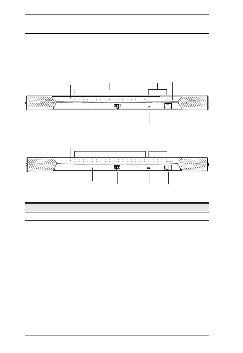
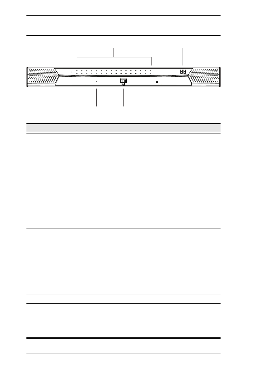
KM0532 / KM0932 Front View
No. Component Description
1 Power LED Lights (blue) to indicate that the unit is receiving power.
2 KVM Port LEDs The KVM Port LEDs provide status information about their
corresponding KVM Ports, They light as follows:
GREEN: The computer connected to its corresponding
port is On Line.
GREEN & Flashing: Its corresponding port is connected to
a cascaded KVM switch.
RED: The port is selected but there's no computer
connected or the connected computer is offline.
The LED does not light when there is no online device
connected to its corresponding port.
ORANGE: The computer attached to the corresponding
port is Selected (has the KVM focus) and is Online.
Lights (green) to indicate that the console module connected
to the corresponding user port is online.
3 Console (User)
Port LEDs
8

Chapter 1. Introduction
No. Component Description
4LAN LED
The LED lights ORANGE to indicate 10 Mbps data
transmission speed.
The LED lights GREEN to indicate 100 Mbps data
transmission speed.
The LED flashes when data is being transmitted
5 Reset Switch Pressing in this button performs a system reset. When the
6 Cover Latch
7 Firmware
Upgrade
Recovery Switch
8 Console (User)
Port
system is reset, the switch beeps, and then the KVM port
LEDs flash in succession until the reset is completed. After
the reset is completed you can login again.
Note: This switch is recessed and must be pushed with a
thin object.
During normal operation and while performing a firmware
upgrade, this switch should be in the NORMAL position. If a
firmware upgrade operation does not complete successfully,
this switch is used to perform a firmware upgrade recovery
(see Firmware Upgrade Recovery, page 162, for details).
This console port is provided on the front panel for easy
administrative access
9
KM0032 / KM0532 / KM0932 User Manual
1 3
654
2
KM0032 Front View
No. Component Description
1 Power LED Lights (blue) to indicate that the unit is receiving power.
2 Port LEDs The Port LEDs provide status information about their
3 Station ID LED The KM0032's Station ID is displayed here. It indicates the
4 Reset Switch Pressing in this button performs a system reset. When the
5 Cover Latch
6 Firmware
Upgrade
Recovery Switch
corresponding KVM Ports, They light as follows:
GREEN: The computer connected to its corresponding
port is On Line.
GREEN & Flashing: Its corresponding port is connected to
a cascaded KVM switch.
RED: The port is selected but there's no computer
connected or the connected computer is offline.
The LED does not light when there is no online device
connected to its corresponding port.
ORANGE: The computer attached to the corresponding
port is Selected (has the KVM focus) and is Online.
KM0032's position in a daisy chained installation. The first
station in the chain has a Station ID of 01; the second has a
Station ID of 02, etc.
system is reset, the switch beeps, and then the KVM port
LEDs flash in succession until the reset is completed. After
the reset is completed you can login again.
Note: This switch is recessed and must be pushed with a
thin object.
During normal operation and while performing a firmware
upgrade, this switch should be in the NORMAL position. If a
firmware upgrade operation does not complete successfully,
this switch is used to perform a firmware upgrade recovery
(see Firmware Upgrade Recovery, page 162, for details).
10
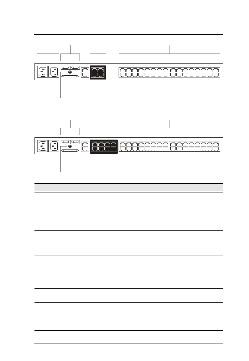
KM0532 / KM0932 Rear View
341 25
67 8
341 25
67 8
KM0532
KM0932
Chapter 1. Introduction
No. Component Description
1 Power Sockets The power cords from the AC source plug in here. The
socket on the left is Socket 1; the socket on the right is
Socket 2.
2 Power Switches These switches power the KM0532 / KM0932 on and off.
The switch on the left is Switch 1 and governs Socket 1; the
switch on the right is Switch 2 and governs Socket 2.
3 PON Port This connector is provided for a Power over the Net™ (PON)
unit to plug into. A PON device allows computers attached to
the switch to be power-managed remotely over the net.
Contact your dealer for more details.
4 Console Ports The Cat 5e or Cat 6 cables from the console modules plug in
here.
5 KVM Ports The Cat 5e or Cat 6 cables that link the KM0532 / KM0932 to
the KVM Adapter Cables (which connect to the computers –
6 Grounding
Terminal
see page 20), plug in here.
The wire used to ground the switch attaches here.
7 CHAIN OUT Port The CHAIN OUT port is used to connect the daisy chain
cable to the CHAIN IN port of a daisy chained KM0032
switch (see page 28).
8 LAN Port The cable from the LAN, WAN, or Intranet plugs in here.
11
KM0032 / KM0532 / KM0932 User Manual
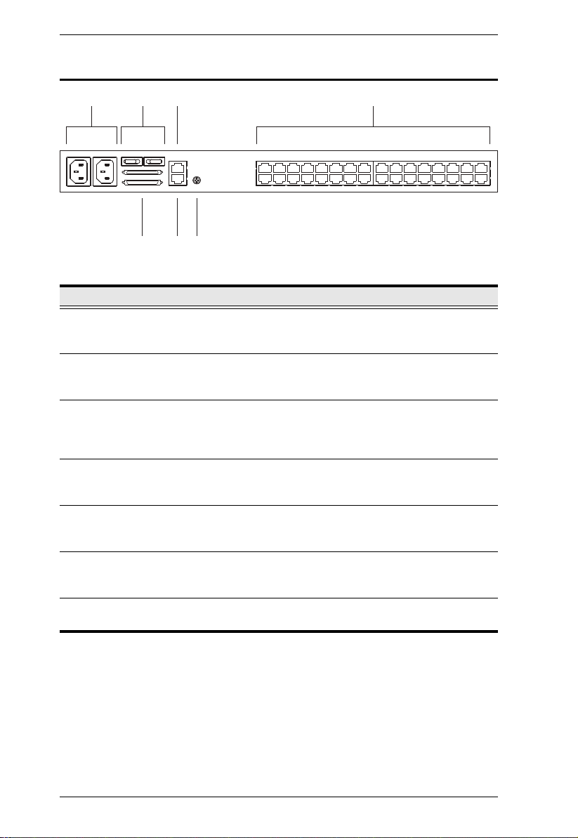
31 24
5 6 7
KM0032 Rear View
No. Component Description
1 Power Sockets The power cords from the AC source plug in here. The
2 Power Switches These switches power the KM0032 on and off. The switch on
3 PON Port This connector is provided for a Power over the Net™ (PON)
4 KVM Ports The Cat 5e or Cat 6 cables that link the KM0032 to the KVM
5 Daisy Chain Ports When daisy chaining KM0032 switches (see page 28), the
6 Firmware
Upgrade Port
7 Grounding
Te rm i n al
socket on the left is Socket 1; the socket on the right is
Socket 2.
the left is Switch 1 and governs Socket 1; the switch on the
right is Switch 2 and governs Socket 2.
unit to plug into. A PON device allows computers attached to
the switch to be power-managed remotely over the net.
Contact your dealer for more details.
Adapter Cables (which connect to the computers – see
page 20), plug in here.
daisy chain cables plug in here. The upper port is the Chain
In port; the lower one is the Chain Out port.
The firmware upgrade cable that transfers the firmware
upgrade data from the administrator's computer to the
KM0032, plugs into this RJ-11 connector.
The wire used to ground the KM0032 attaches here.
12
Chapter 2
Hardware Setup
Overview
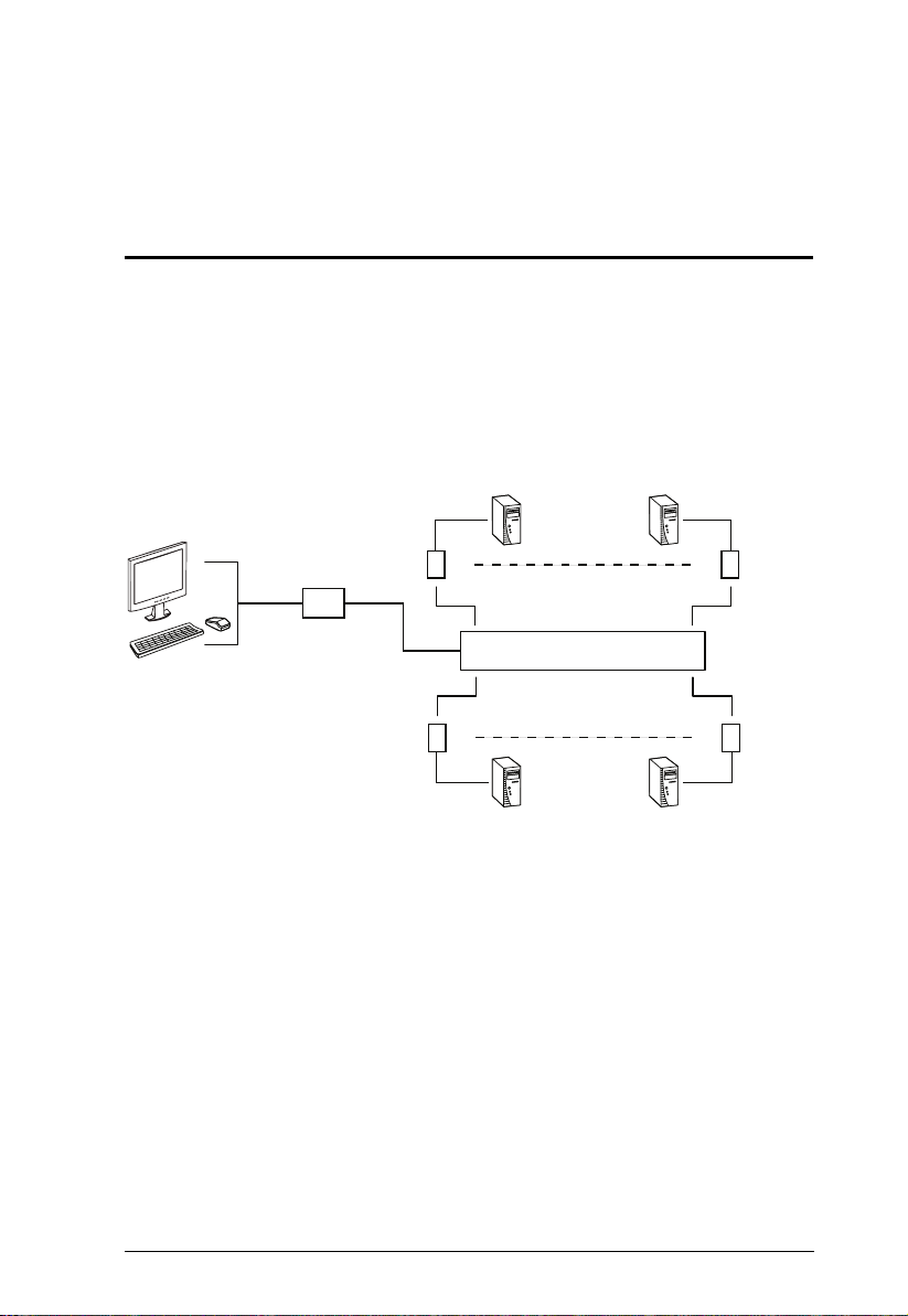
For convenience and flexibility, the KM0532 / KM0932’s design utilizes
console modules that act as signal translation intermediaries between the KVM
consoles and the KVM switch. This allows PS/2 and USB interface consoles to
coexist on the same installation.
The design also uses KVM adapter cables, that serve as intermediaries between
the KVM switch and the computers, and provides the basis for multiplatform
support:
KA7120
KA9120
KA7130
KA9130
KA7230
KA7240
KM0532 / KM0932
KA7140
KA9140
KA7170
KA9170
KA7176
KA7166
KA7168
KA7169
A separate console module is required for each KVM console; likewise, a
separate KVM adapter cable is required for each computer. For a listing of
compatible console modules,
see Consoles, page 5. For a listing of compatible
KVM adapter cables, see Cables, page 6.
As a cost-saving feature, KM0032 switches, can be daisy chained down from
a KM0532 or KM0932. Since devices connected to them are accessed through
one of the KM0532 or KM0932 consoles, they don’t require a console of their
own.
13
KM0032 / KM0532 / KM0932 User Manual
1. Important safety information regarding the placement of this
device is provided on page 179. Please review it before
proceeding.
2. Make sure that power to all the devices you will be connecting
up has been turned off. You must unplug the power cords of any
computers that have the Keyboard Power On function.
Before you Begin
Stacking and Rack Mounting
The KM0032 / KM0532 / KM0932 can be stacked on the desktop or rack
mounted in a variety of ways. The following sections take you through the
procedures for each method.
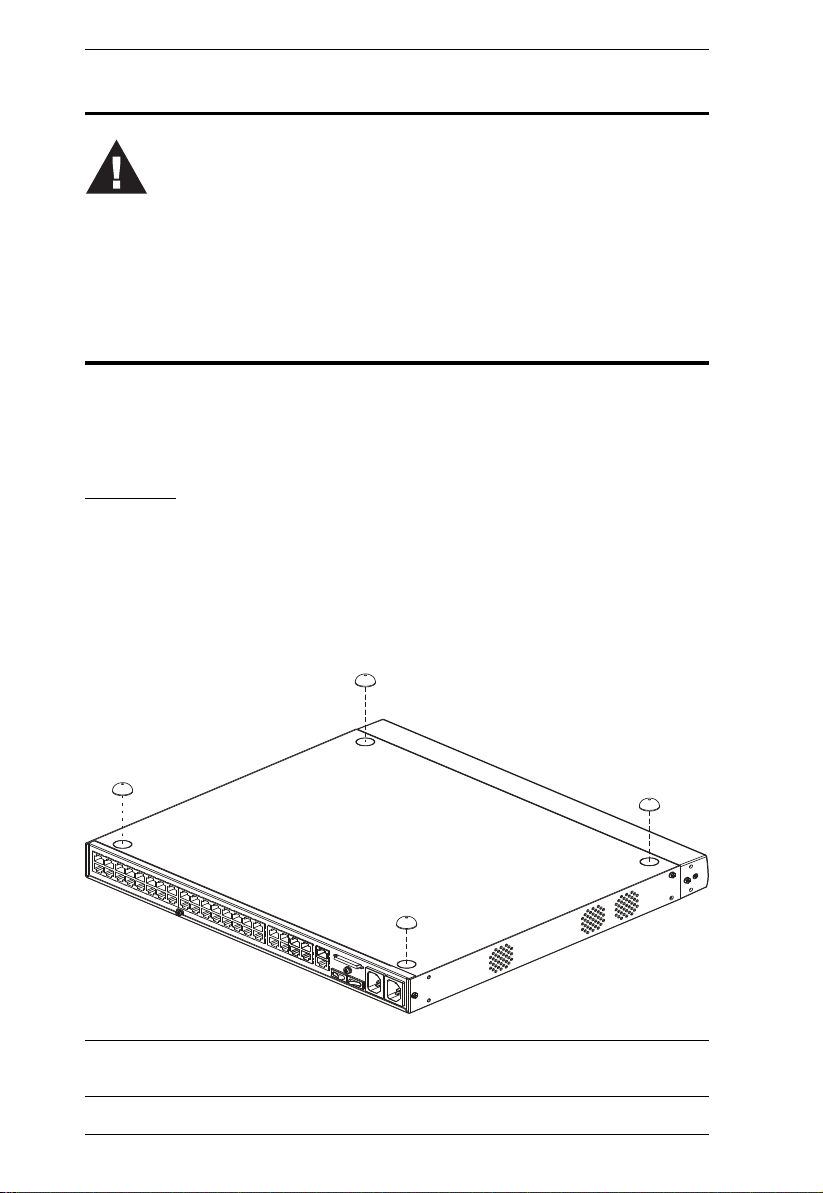
Stacking
The KM0032 / KM0532 / KM0932 can be placed on any appropriate level
surface that can safely support its weight plus the weight of its attached cables.
To place the switch, or to stack units if you are daisy chaining them, remove
the backing material from the bottom of the rubber feet that came with this
package, and stick them onto the switch’s bottom panel at the corners, as
shown in the diagram, below:
Note: To ensure adequate ventilation, allow at least 5.1 cm on each side, and
12.7cm at the back for power cord and cable clearance.
14
Chapter 2. Hardware Setup
Phillips head hex
M3 x 6
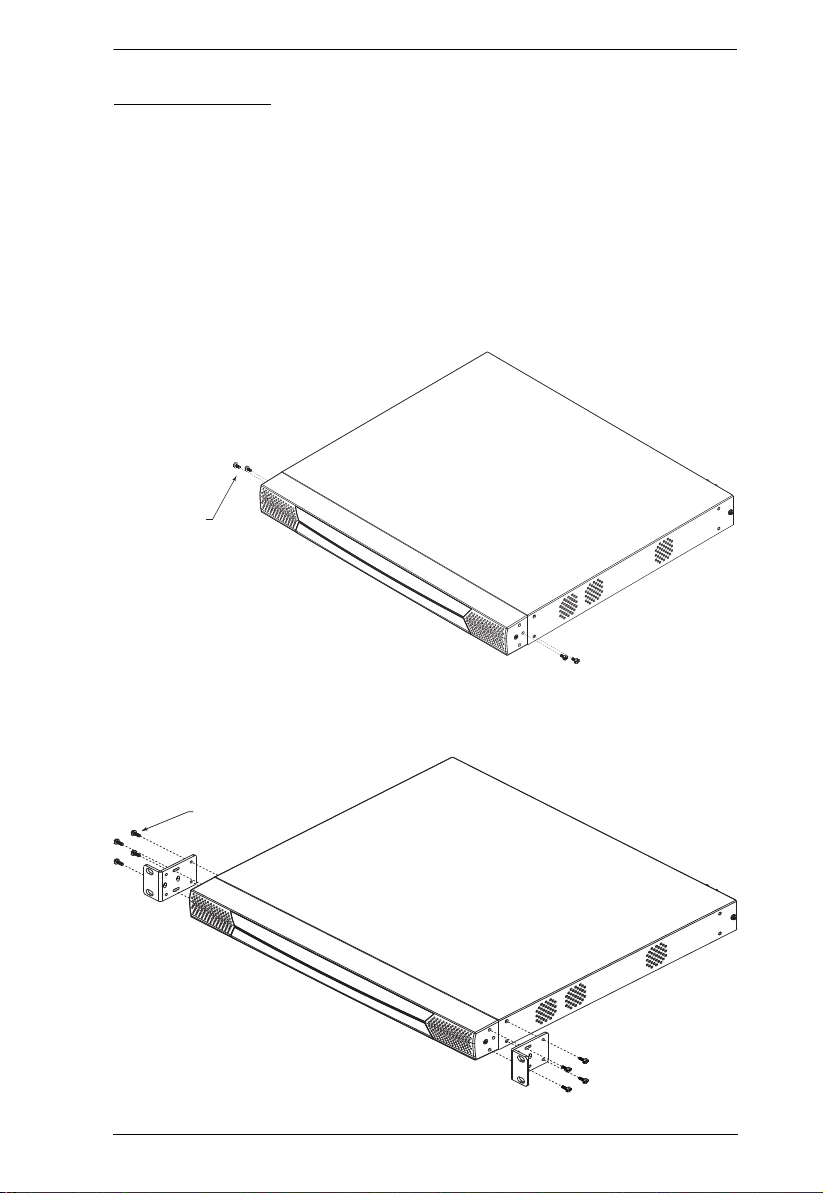
Rack Mounting
The KM0032 / KM0532 / KM0932 can be mounted in a 19" (1U) rack. The
mounting brackets can screw into either the front or the back of the unit so that
it can attach to the front or the back of the rack.
Rack Mounting - Front
To mount the unit at the front of the rack, do the following:
1. Remove the two screws at the front of the unit, as shown in the diagram
below:
2. Use the M3 x 8 Phillips head hex screws supplied with the rack mount kit
to screw the rack mounting brackets into the front of the unit:
Phillips head hex
M3 x 8
15
KM0032 / KM0532 / KM0932 User Manual
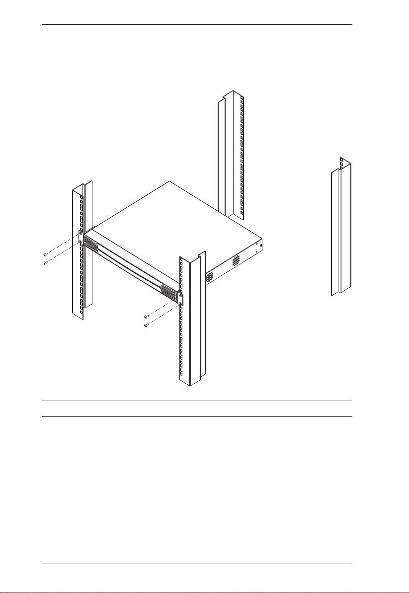
3. Position the device in the front of the rack and align the holes in the
mounting brackets with the holes in the rack.
4. Screw the mounting brackets to the rack.
Note: Cage nuts are provided for racks that are not prethreaded.
16
 Loading...