

ATEN KL1516AiN Service Manual

Dual Rail LCD KVM Switch
KL1508Ai / KL1516Ai
User Manual
www.aten.com

KL1508Ai / KL1516Ai User Manual
EMC Information
FEDERAL COMMUNICATIONS COMMISSION INTERFERENCE
STATEMENT: This equipment has been tested and found to comply with the
limits for a Class A digital device, pursuant to Part 15 of the FCC Rules. These
limits are designed to provide reasonable protection against harmful
interference when the equipment is operated in a commercial environment.
This equipment generates, uses, and can radiate radio frequency energy and, if
not installed and used in accordance with the instruction manual, may cause
harmful interference to radio communications. Operation of this equipment in
a residential area is likely to cause harmful interference in which case the user
will be required to correct the interference at his own expense.
The device complies with Part 15 of the FCC Rules. Operation is subject to the
following two conditions: (1) this device may not cause harmful interference,
and (2) this device must accept any interference received, including
interference that may cause undesired operation.
FCC Caution: Any changes or modifications not expressly approved by the
party responsible for compliance could void the user's authority to operate this
equipment.
CE Warning: This is a class A product. In a domestic environment this
product may cause radio interference in which case the user may be required to
take adequate measures.
Suggestion: Shielded twisted pair (STP) cables must be used with the unit to
ensure compliance with FCC & CE standards.
KCC Statement
유선 제품용 /A 급 기기 ( 업무용 방송 통신 기기 )
이 기기는 업무용 (A 급 )전자파적합기기로서 판매자 또는 사용자는 이
점을 주의하시기 바라며 ,가정 외의 지역에서 사용하는 것을 목적으로
합니다 .
ii
KL1508Ai / KL1516Ai User Manual
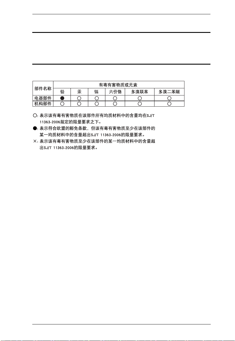
RoHS
This product is RoHS compliant.
SJ/T 11364-2006
The following contains information that relates to China.
iii

KL1508Ai / KL1516Ai User Manual
User Information
Online Registration
Be sure to register your product at our online support center:
International http://eservice.aten.com
Telephone Support
For telephone support, call this number:
International 886-2-8692-6959
China 86-10-5255-0110
Japan 81-3-5615-5811
Korea 82-2-467-6789
North America 1-888-999-ATEN ext 4988
United Kingdom 44-8-4481-58923
iv

KL1508Ai / KL1516Ai User Manual
User Notice
All information, documentation, and specifications contained in this manual
are subject to change without prior notification by the manufacturer. The
manufacturer makes no representations or warranties, either expressed or
implied, with respect to the contents hereof and specifically disclaims any
warranties as to merchantability or fitness for any particular purpose. Any of
the manufacturer's software described in this manual is sold or licensed `as is'.
Should the programs prove defective following their purchase, the buyer (and
not the manufacturer, its distributor, or its dealer), assumes the entire cost of all
necessary servicing, repair and any incidental or consequential damages
resulting from any defect in the software.
The manufacturer of this system is not responsible for any radio and/or TV
interference caused by unauthorized modifications to this device. It is the
responsibility of the user to correct such interference.
The manufacturer is not responsible for any damage incurred in the operation
of this system if the correct operational voltage setting was not selected prior
to operation. PLEASE VERIFY THAT THE VOLTAGE SETTING IS
CORRECT BEFORE USE.
A typical LCD (Liquid Crystal Display) monitor has millions of pixels. A dead
pixel refers to a pixel with a defect in its ability to display the correct color
output. It most often looks like a tiny black or white spot on your screen,
although it can be any other color. Since even a tiny dust particle on one of the
pixels during the manufacturing process or a slight bump during shipping can
create a dead pixel, the ISO 13406-2 norm defines 4 classes of acceptable
screens with dead pixels--Class 1 is the best; Class 4 is the worst. Almost all
manufacturers use Class 2 to establish their warranties, which allows a certain
amount of dead pixels to exist before they will replace the screen. Since the
manufacturers consider these screens to be acceptable under ISO
specifications, we cannot be responsible for replacement or warranty of the
TFT LCD panel.
v

KL1508Ai / KL1516Ai User Manual
Copyright © 2016 ATEN® International Co., Ltd.
Manual Date: 2016-05-25
Altusen and the Altusen logo are registered trademarks of ATEN International Co., Ltd. All rights reserved.
All other brand names and trademarks are the registered property of their respective owners.
Package Contents
Basic Package
The basic KL1508Ai / KL1516Ai package consists of:
1 KL1508Ai or KL1516Ai Dual Rail LCD KVM Switch
1Power Cord
1 Standard Rack Mount Kit
1 Firmware Upgrade Cable
1 User Instructions*
Optional Equipment
Depending on any optional equipment that you may have purchased, one of the
following may be included in your package:
Standard Rack Mounting Kit - Long
Easy-Installation Rack Mounting Kit - Short
Easy-Installation Rack Mounting Kit - Long
Check to make sure that all of the components are present and in good order.
If anything is missing, or was damaged in shipping, contact your dealer.
Read this manual thoroughly and follow the installation and operation
procedures carefully to prevent any damage to the switch or to any other
devices on the KL1508Ai / KL1516Ai installation.
* Changes may have been made to the manual since it was published. Please
visit our Website to check for the most up-to-date version.
vi

KL1508Ai / KL1516Ai User Manual
Contents
EMC Information. . . . . . . . . . . . . . . . . . . . . . . . . . . . . . . . . . . . . . . . . . . . .ii
RoHS. . . . . . . . . . . . . . . . . . . . . . . . . . . . . . . . . . . . . . . . . . . . . . . . . . . . . .iii
SJ/T 11364-2006. . . . . . . . . . . . . . . . . . . . . . . . . . . . . . . . . . . . . . . . . . . . .iii
User Information . . . . . . . . . . . . . . . . . . . . . . . . . . . . . . . . . . . . . . . . . . . . iv
Online Registration . . . . . . . . . . . . . . . . . . . . . . . . . . . . . . . . . . . . . . . iv
Telephone Support . . . . . . . . . . . . . . . . . . . . . . . . . . . . . . . . . . . . . . . iv
User Notice . . . . . . . . . . . . . . . . . . . . . . . . . . . . . . . . . . . . . . . . . . . . . .v
Package Contents. . . . . . . . . . . . . . . . . . . . . . . . . . . . . . . . . . . . . . . . . . . vi
Basic Package. . . . . . . . . . . . . . . . . . . . . . . . . . . . . . . . . . . . . . . . . . . vi
Optional Equipment. . . . . . . . . . . . . . . . . . . . . . . . . . . . . . . . . . . . . . . vi
About This Manual . . . . . . . . . . . . . . . . . . . . . . . . . . . . . . . . . . . . . . . . . .xiii
Conventions . . . . . . . . . . . . . . . . . . . . . . . . . . . . . . . . . . . . . . . . . . . .xv
Product Information. . . . . . . . . . . . . . . . . . . . . . . . . . . . . . . . . . . . . . . . . . xv
Chapter 1.
Introduction
Overview. . . . . . . . . . . . . . . . . . . . . . . . . . . . . . . . . . . . . . . . . . . . . . . . . . .1
Features . . . . . . . . . . . . . . . . . . . . . . . . . . . . . . . . . . . . . . . . . . . . . . . . . . .4
Hardware. . . . . . . . . . . . . . . . . . . . . . . . . . . . . . . . . . . . . . . . . . . . . . . .4
Management . . . . . . . . . . . . . . . . . . . . . . . . . . . . . . . . . . . . . . . . . . . . .4
Easy-to-Use Interface . . . . . . . . . . . . . . . . . . . . . . . . . . . . . . . . . . . . . .5
Advanced Security . . . . . . . . . . . . . . . . . . . . . . . . . . . . . . . . . . . . . . . .5
Virtual Remote Desktop . . . . . . . . . . . . . . . . . . . . . . . . . . . . . . . . . . . .6
Requirements . . . . . . . . . . . . . . . . . . . . . . . . . . . . . . . . . . . . . . . . . . . . . . .7
General . . . . . . . . . . . . . . . . . . . . . . . . . . . . . . . . . . . . . . . . . . . . . . . . .7
External Console. . . . . . . . . . . . . . . . . . . . . . . . . . . . . . . . . . . . . . . . . .7
Computers. . . . . . . . . . . . . . . . . . . . . . . . . . . . . . . . . . . . . . . . . . . . . . .7
KVM Adapter Cables. . . . . . . . . . . . . . . . . . . . . . . . . . . . . . . . . . . . . . .7
Operating Systems . . . . . . . . . . . . . . . . . . . . . . . . . . . . . . . . . . . . . . . .8
Components . . . . . . . . . . . . . . . . . . . . . . . . . . . . . . . . . . . . . . . . . . . . . . . .9
Front View. . . . . . . . . . . . . . . . . . . . . . . . . . . . . . . . . . . . . . . . . . . . . . .9
Keyboard Module . . . . . . . . . . . . . . . . . . . . . . . . . . . . . . . . . . . . . . . .10
LCD Module . . . . . . . . . . . . . . . . . . . . . . . . . . . . . . . . . . . . . . . . . . . .11
Rear View . . . . . . . . . . . . . . . . . . . . . . . . . . . . . . . . . . . . . . . . . . . . . .12
Chapter 2.
Hardware Setup
Before You Begin . . . . . . . . . . . . . . . . . . . . . . . . . . . . . . . . . . . . . . . . . . .13
Standard Rack Mounting. . . . . . . . . . . . . . . . . . . . . . . . . . . . . . . . . . . . . .14
Single Stage Installation . . . . . . . . . . . . . . . . . . . . . . . . . . . . . . . . . . . . . .16
Daisy Chaining . . . . . . . . . . . . . . . . . . . . . . . . . . . . . . . . . . . . . . . . . . . . .20
Chapter 3.
Basic Operation
Opening the Console . . . . . . . . . . . . . . . . . . . . . . . . . . . . . . . . . . . . . . . .23
vii

KL1508Ai / KL1516Ai User Manual
Opening Separately . . . . . . . . . . . . . . . . . . . . . . . . . . . . . . . . . . . . . .23
Opening Together. . . . . . . . . . . . . . . . . . . . . . . . . . . . . . . . . . . . . . . .25
Operating Precautions . . . . . . . . . . . . . . . . . . . . . . . . . . . . . . . . . . . .26
Closing the Console . . . . . . . . . . . . . . . . . . . . . . . . . . . . . . . . . . . . . . . . . 27
LCD OSD Configuration . . . . . . . . . . . . . . . . . . . . . . . . . . . . . . . . . . . . . .29
The LCD Buttons. . . . . . . . . . . . . . . . . . . . . . . . . . . . . . . . . . . . . . . . .29
The Adjustment Settings. . . . . . . . . . . . . . . . . . . . . . . . . . . . . . . . . . .30
Port Selection . . . . . . . . . . . . . . . . . . . . . . . . . . . . . . . . . . . . . . . . . . . . . .31
Manual . . . . . . . . . . . . . . . . . . . . . . . . . . . . . . . . . . . . . . . . . . . . . . . . 31
OSD / GUI. . . . . . . . . . . . . . . . . . . . . . . . . . . . . . . . . . . . . . . . . . . . . .31
Hotkeys. . . . . . . . . . . . . . . . . . . . . . . . . . . . . . . . . . . . . . . . . . . . . . . .31
Hot Plugging. . . . . . . . . . . . . . . . . . . . . . . . . . . . . . . . . . . . . . . . . . . . . . . 32
Hot Plugging Stations . . . . . . . . . . . . . . . . . . . . . . . . . . . . . . . . . . . . .32
Hot Plugging KVM Ports . . . . . . . . . . . . . . . . . . . . . . . . . . . . . . . . . . .32
Hot Plugging Console Ports . . . . . . . . . . . . . . . . . . . . . . . . . . . . . . . .32
Powering Off and Restarting. . . . . . . . . . . . . . . . . . . . . . . . . . . . . . . . . . .33
Port ID Numbering . . . . . . . . . . . . . . . . . . . . . . . . . . . . . . . . . . . . . . . . . .33
Chapter 4.
OSD Operation
OSD Overview . . . . . . . . . . . . . . . . . . . . . . . . . . . . . . . . . . . . . . . . . . . . . 35
Manufacturing Number . . . . . . . . . . . . . . . . . . . . . . . . . . . . . . . . . . . . 36
OSD Navigation . . . . . . . . . . . . . . . . . . . . . . . . . . . . . . . . . . . . . . . . . . . .37
OSD Main Screen Headings. . . . . . . . . . . . . . . . . . . . . . . . . . . . . . . . . . .37
OSD Functions . . . . . . . . . . . . . . . . . . . . . . . . . . . . . . . . . . . . . . . . . . . . .38
F1: GOTO. . . . . . . . . . . . . . . . . . . . . . . . . . . . . . . . . . . . . . . . . . . . . .38
F2: LIST . . . . . . . . . . . . . . . . . . . . . . . . . . . . . . . . . . . . . . . . . . . . . . .39
F3: SET. . . . . . . . . . . . . . . . . . . . . . . . . . . . . . . . . . . . . . . . . . . . . . . .40
F4: ADM . . . . . . . . . . . . . . . . . . . . . . . . . . . . . . . . . . . . . . . . . . . . . . .43
F5: SKP. . . . . . . . . . . . . . . . . . . . . . . . . . . . . . . . . . . . . . . . . . . . . . . .46
F6: BRC . . . . . . . . . . . . . . . . . . . . . . . . . . . . . . . . . . . . . . . . . . . . . . .47
F7: SCAN . . . . . . . . . . . . . . . . . . . . . . . . . . . . . . . . . . . . . . . . . . . . . .48
F8: LOUT . . . . . . . . . . . . . . . . . . . . . . . . . . . . . . . . . . . . . . . . . . . . . .48
Chapter 5.
Hotkey Operation
Hotkey Port Control . . . . . . . . . . . . . . . . . . . . . . . . . . . . . . . . . . . . . . . . .49
Invoking Hotkey Mode . . . . . . . . . . . . . . . . . . . . . . . . . . . . . . . . . . . . . . .50
Selecting the Active Port. . . . . . . . . . . . . . . . . . . . . . . . . . . . . . . . . . . . . .51
Auto Scan Mode Switching. . . . . . . . . . . . . . . . . . . . . . . . . . . . . . . . . . . . 52
Skip Mode Switching . . . . . . . . . . . . . . . . . . . . . . . . . . . . . . . . . . . . . . . .54
Computer Keyboard / Mouse Reset . . . . . . . . . . . . . . . . . . . . . . . . . . . . . 55
Setting the Hotkey Beeper ON/OFF . . . . . . . . . . . . . . . . . . . . . . . . . . . . . 55
Setting the Hotkey key combination . . . . . . . . . . . . . . . . . . . . . . . . . . . . . 56
Setting the OSD Hotkey combination. . . . . . . . . . . . . . . . . . . . . . . . . . . .56
Setting the Port Operating System. . . . . . . . . . . . . . . . . . . . . . . . . . . . . .57
Restore the Default Values. . . . . . . . . . . . . . . . . . . . . . . . . . . . . . . . . . . .57
viii

KL1508Ai / KL1516Ai User Manual
Hotkey Summary Table. . . . . . . . . . . . . . . . . . . . . . . . . . . . . . . . . . . . . . .58
Chapter 6.
Keyboard Emulation
Mac Keyboard. . . . . . . . . . . . . . . . . . . . . . . . . . . . . . . . . . . . . . . . . . . . . .59
Sun Keyboard . . . . . . . . . . . . . . . . . . . . . . . . . . . . . . . . . . . . . . . . . . . . . .60
Chapter 7.
Logging In
Overview. . . . . . . . . . . . . . . . . . . . . . . . . . . . . . . . . . . . . . . . . . . . . . . . . .61
Local Login . . . . . . . . . . . . . . . . . . . . . . . . . . . . . . . . . . . . . . . . . . . . . . . .62
Browser Login. . . . . . . . . . . . . . . . . . . . . . . . . . . . . . . . . . . . . . . . . . . . . .63
Windows Client AP Login . . . . . . . . . . . . . . . . . . . . . . . . . . . . . . . . . . . . .64
The Windows Client AP Connection Screen. . . . . . . . . . . . . . . . . . . .65
Connecting – Windows Client AP . . . . . . . . . . . . . . . . . . . . . . . . . . . .66
Java Client AP Login. . . . . . . . . . . . . . . . . . . . . . . . . . . . . . . . . . . . . . . . .67
The Java Client AP Connection Screen . . . . . . . . . . . . . . . . . . . . . . .68
Connecting – Java Client AP. . . . . . . . . . . . . . . . . . . . . . . . . . . . . . . .69
Chapter 8.
The User Interface
Overview. . . . . . . . . . . . . . . . . . . . . . . . . . . . . . . . . . . . . . . . . . . . . . . . . .71
The Web Browser Main Page. . . . . . . . . . . . . . . . . . . . . . . . . . . . . . . . . .71
Page Components. . . . . . . . . . . . . . . . . . . . . . . . . . . . . . . . . . . . . . . .72
The Tab Bar . . . . . . . . . . . . . . . . . . . . . . . . . . . . . . . . . . . . . . . . . . . .73
The AP GUI Main Page. . . . . . . . . . . . . . . . . . . . . . . . . . . . . . . . . . . . . . .74
The Control Panel. . . . . . . . . . . . . . . . . . . . . . . . . . . . . . . . . . . . . . . . . . .75
WinClient Control Panel . . . . . . . . . . . . . . . . . . . . . . . . . . . . . . . . . . .75
WinClient Control Panel Functions . . . . . . . . . . . . . . . . . . . . . . . . . . .77
Macros. . . . . . . . . . . . . . . . . . . . . . . . . . . . . . . . . . . . . . . . . . . . . . . . .79
Video Settings. . . . . . . . . . . . . . . . . . . . . . . . . . . . . . . . . . . . . . . . . . .88
The Message Board . . . . . . . . . . . . . . . . . . . . . . . . . . . . . . . . . . . . . .91
Zoom. . . . . . . . . . . . . . . . . . . . . . . . . . . . . . . . . . . . . . . . . . . . . . . . . .93
The On-Screen Keyboard . . . . . . . . . . . . . . . . . . . . . . . . . . . . . . . . . .94
Mouse Pointer Type . . . . . . . . . . . . . . . . . . . . . . . . . . . . . . . . . . . . . .96
Mouse DynaSync Mode . . . . . . . . . . . . . . . . . . . . . . . . . . . . . . . . . . .97
Control Panel Configuration . . . . . . . . . . . . . . . . . . . . . . . . . . . . . . . .99
The Java Control Panel. . . . . . . . . . . . . . . . . . . . . . . . . . . . . . . . . . .101
Chapter 9.
Port Access
Overview. . . . . . . . . . . . . . . . . . . . . . . . . . . . . . . . . . . . . . . . . . . . . . . . .103
Browser GUI . . . . . . . . . . . . . . . . . . . . . . . . . . . . . . . . . . . . . . . . . . .103
AP GUI . . . . . . . . . . . . . . . . . . . . . . . . . . . . . . . . . . . . . . . . . . . . . . .103
The Sidebar. . . . . . . . . . . . . . . . . . . . . . . . . . . . . . . . . . . . . . . . . . . . . . .105
The Sidebar Tree Structure. . . . . . . . . . . . . . . . . . . . . . . . . . . . . . . .105
View Filter . . . . . . . . . . . . . . . . . . . . . . . . . . . . . . . . . . . . . . . . . . . . .106
ix

KL1508Ai / KL1516Ai User Manual
Connections . . . . . . . . . . . . . . . . . . . . . . . . . . . . . . . . . . . . . . . . . . . . . .107
Device Level . . . . . . . . . . . . . . . . . . . . . . . . . . . . . . . . . . . . . . . . . . .107
Port Level . . . . . . . . . . . . . . . . . . . . . . . . . . . . . . . . . . . . . . . . . . . . . 108
User Preferences . . . . . . . . . . . . . . . . . . . . . . . . . . . . . . . . . . . . . . . . . .109
Sessions. . . . . . . . . . . . . . . . . . . . . . . . . . . . . . . . . . . . . . . . . . . . . . . . .111
Access Rights. . . . . . . . . . . . . . . . . . . . . . . . . . . . . . . . . . . . . . . . . . . . .112
Browser GUI Interface. . . . . . . . . . . . . . . . . . . . . . . . . . . . . . . . . . . . 112
AP GUI Interface. . . . . . . . . . . . . . . . . . . . . . . . . . . . . . . . . . . . . . . .113
Saving Changes . . . . . . . . . . . . . . . . . . . . . . . . . . . . . . . . . . . . . . . . 113
Chapter 10.
User Management
Overview . . . . . . . . . . . . . . . . . . . . . . . . . . . . . . . . . . . . . . . . . . . . . . . . .115
Browser GUI . . . . . . . . . . . . . . . . . . . . . . . . . . . . . . . . . . . . . . . . . . .115
AP GUI . . . . . . . . . . . . . . . . . . . . . . . . . . . . . . . . . . . . . . . . . . . . . . .115
Users . . . . . . . . . . . . . . . . . . . . . . . . . . . . . . . . . . . . . . . . . . . . . . . . . . .116
Adding Users. . . . . . . . . . . . . . . . . . . . . . . . . . . . . . . . . . . . . . . . . . .116
Modifying User Accounts . . . . . . . . . . . . . . . . . . . . . . . . . . . . . . . . .119
Deleting User Accounts. . . . . . . . . . . . . . . . . . . . . . . . . . . . . . . . . . .119
Device Assignment. . . . . . . . . . . . . . . . . . . . . . . . . . . . . . . . . . . . . . . . .120
Assigning Device Permissions From the User’s Notebook. . . . . . . .120
Chapter 11.
Device Management
KVM Devices . . . . . . . . . . . . . . . . . . . . . . . . . . . . . . . . . . . . . . . . . . . . .123
Device Information . . . . . . . . . . . . . . . . . . . . . . . . . . . . . . . . . . . . . .123
Network. . . . . . . . . . . . . . . . . . . . . . . . . . . . . . . . . . . . . . . . . . . . . . . 126
ANMS . . . . . . . . . . . . . . . . . . . . . . . . . . . . . . . . . . . . . . . . . . . . . . . . 130
Security. . . . . . . . . . . . . . . . . . . . . . . . . . . . . . . . . . . . . . . . . . . . . . .135
Port Configuration. . . . . . . . . . . . . . . . . . . . . . . . . . . . . . . . . . . . . . .142
Date/Time . . . . . . . . . . . . . . . . . . . . . . . . . . . . . . . . . . . . . . . . . . . . .144
Chapter 12.
Log
Overview . . . . . . . . . . . . . . . . . . . . . . . . . . . . . . . . . . . . . . . . . . . . . . . . .147
Browser GUI . . . . . . . . . . . . . . . . . . . . . . . . . . . . . . . . . . . . . . . . . . .147
AP GUI . . . . . . . . . . . . . . . . . . . . . . . . . . . . . . . . . . . . . . . . . . . . . . .147
Log Information. . . . . . . . . . . . . . . . . . . . . . . . . . . . . . . . . . . . . . . . . . . .148
Chapter 13.
Maintenance
Overview . . . . . . . . . . . . . . . . . . . . . . . . . . . . . . . . . . . . . . . . . . . . . . . . .149
Browser GUI . . . . . . . . . . . . . . . . . . . . . . . . . . . . . . . . . . . . . . . . . . .149
AP GUI . . . . . . . . . . . . . . . . . . . . . . . . . . . . . . . . . . . . . . . . . . . . . . .150
Device Firmware Upgrade (IP Card) . . . . . . . . . . . . . . . . . . . . . . . . . . .151
Adapter Firmware Upgrade (Mainboard and KVM Adapter Cables) . . . 152
Mainboard Firmware Upgrade . . . . . . . . . . . . . . . . . . . . . . . . . . . . . 152
x

KL1508Ai / KL1516Ai User Manual
KVM Adapter Cables Firmware Upgrade . . . . . . . . . . . . . . . . . . . . .153
Firmware Upgrade Recovery . . . . . . . . . . . . . . . . . . . . . . . . . . . . . . . . .155
Device Firmware (IP Card) . . . . . . . . . . . . . . . . . . . . . . . . . . . . . . . .155
Adapter Firmware (Mainboard and KVM Adapter Cables) . . . . . . . .155
Backup/Restore. . . . . . . . . . . . . . . . . . . . . . . . . . . . . . . . . . . . . . . . . . . .156
Backup . . . . . . . . . . . . . . . . . . . . . . . . . . . . . . . . . . . . . . . . . . . . . . .156
System Operation . . . . . . . . . . . . . . . . . . . . . . . . . . . . . . . . . . . . . . . . . . 157
Clear Port Names:. . . . . . . . . . . . . . . . . . . . . . . . . . . . . . . . . . . . . . .157
Reset to Default: . . . . . . . . . . . . . . . . . . . . . . . . . . . . . . . . . . . . . . . .157
System Reset:. . . . . . . . . . . . . . . . . . . . . . . . . . . . . . . . . . . . . . . . . .157
Chapter 14.
The Firmware Upgrade Utility
Introduction . . . . . . . . . . . . . . . . . . . . . . . . . . . . . . . . . . . . . . . . . . . . . . .159
Before You Begin . . . . . . . . . . . . . . . . . . . . . . . . . . . . . . . . . . . . . . .159
Performing the Upgrade . . . . . . . . . . . . . . . . . . . . . . . . . . . . . . . . . .161
Firmware Upgrade Recovery . . . . . . . . . . . . . . . . . . . . . . . . . . . . . .165
Chapter 15.
Download
Overview. . . . . . . . . . . . . . . . . . . . . . . . . . . . . . . . . . . . . . . . . . . . . . . . .167
Chapter 16.
Port Operation
Overview. . . . . . . . . . . . . . . . . . . . . . . . . . . . . . . . . . . . . . . . . . . . . . . . .169
Connecting to a Port . . . . . . . . . . . . . . . . . . . . . . . . . . . . . . . . . . . . . . . .170
The Port Toolbar. . . . . . . . . . . . . . . . . . . . . . . . . . . . . . . . . . . . . . . . . . .171
The Toolbar Icons . . . . . . . . . . . . . . . . . . . . . . . . . . . . . . . . . . . . . . .172
Toolbar Hotkey Port Switching . . . . . . . . . . . . . . . . . . . . . . . . . . . . .173
Recalling the Port Access Page . . . . . . . . . . . . . . . . . . . . . . . . . . . .175
GUI Hotkey Summary Table . . . . . . . . . . . . . . . . . . . . . . . . . . . . . . .175
Panel Array Mode . . . . . . . . . . . . . . . . . . . . . . . . . . . . . . . . . . . . . . . . . .176
Panel Array Toolbar . . . . . . . . . . . . . . . . . . . . . . . . . . . . . . . . . . . . .177
Multiuser Operation. . . . . . . . . . . . . . . . . . . . . . . . . . . . . . . . . . . . . . . . .178
Chapter 17.
The Log Server
Installation. . . . . . . . . . . . . . . . . . . . . . . . . . . . . . . . . . . . . . . . . . . . . . . .179
Starting Up . . . . . . . . . . . . . . . . . . . . . . . . . . . . . . . . . . . . . . . . . . . . . . .180
The Menu Bar . . . . . . . . . . . . . . . . . . . . . . . . . . . . . . . . . . . . . . . . . . . . .181
Configure. . . . . . . . . . . . . . . . . . . . . . . . . . . . . . . . . . . . . . . . . . . . . .181
Events . . . . . . . . . . . . . . . . . . . . . . . . . . . . . . . . . . . . . . . . . . . . . . . .182
Options . . . . . . . . . . . . . . . . . . . . . . . . . . . . . . . . . . . . . . . . . . . . . . .184
Help. . . . . . . . . . . . . . . . . . . . . . . . . . . . . . . . . . . . . . . . . . . . . . . . . .184
The Log Server Main Screen . . . . . . . . . . . . . . . . . . . . . . . . . . . . . . . . .185
Overview . . . . . . . . . . . . . . . . . . . . . . . . . . . . . . . . . . . . . . . . . . . . . .185
The List Panel . . . . . . . . . . . . . . . . . . . . . . . . . . . . . . . . . . . . . . . . . .186
xi

KL1508Ai / KL1516Ai User Manual
The Event Panel . . . . . . . . . . . . . . . . . . . . . . . . . . . . . . . . . . . . . . . .186
Appendix
Safety Instructions . . . . . . . . . . . . . . . . . . . . . . . . . . . . . . . . . . . . . . . . .187
General . . . . . . . . . . . . . . . . . . . . . . . . . . . . . . . . . . . . . . . . . . . . . . . 187
Rack Mounting . . . . . . . . . . . . . . . . . . . . . . . . . . . . . . . . . . . . . . . . .189
Technical Support. . . . . . . . . . . . . . . . . . . . . . . . . . . . . . . . . . . . . . . . . .190
International . . . . . . . . . . . . . . . . . . . . . . . . . . . . . . . . . . . . . . . . . . .190
North America. . . . . . . . . . . . . . . . . . . . . . . . . . . . . . . . . . . . . . . . . .190
Specifications . . . . . . . . . . . . . . . . . . . . . . . . . . . . . . . . . . . . . . . . . . . . . 191
IP Address Determination. . . . . . . . . . . . . . . . . . . . . . . . . . . . . . . . . . . . 193
The Local Console . . . . . . . . . . . . . . . . . . . . . . . . . . . . . . . . . . . . . . 193
IP Installer. . . . . . . . . . . . . . . . . . . . . . . . . . . . . . . . . . . . . . . . . . . . .193
Browser. . . . . . . . . . . . . . . . . . . . . . . . . . . . . . . . . . . . . . . . . . . . . . . 194
IPv6. . . . . . . . . . . . . . . . . . . . . . . . . . . . . . . . . . . . . . . . . . . . . . . . . . . . .195
Link Local IPv6 Address . . . . . . . . . . . . . . . . . . . . . . . . . . . . . . . . . . 195
IPv6 Stateless Autoconfiguration . . . . . . . . . . . . . . . . . . . . . . . . . . .196
Trusted Certificates. . . . . . . . . . . . . . . . . . . . . . . . . . . . . . . . . . . . . . . . . 197
Overview. . . . . . . . . . . . . . . . . . . . . . . . . . . . . . . . . . . . . . . . . . . . . .197
Installing the Certificate. . . . . . . . . . . . . . . . . . . . . . . . . . . . . . . . . . .198
Certificate Trusted. . . . . . . . . . . . . . . . . . . . . . . . . . . . . . . . . . . . . . .199
Self-Signed Private Certificates . . . . . . . . . . . . . . . . . . . . . . . . . . . . . . .200
Examples . . . . . . . . . . . . . . . . . . . . . . . . . . . . . . . . . . . . . . . . . . . . .200
Importing the Files. . . . . . . . . . . . . . . . . . . . . . . . . . . . . . . . . . . . . . . 200
Troubleshooting . . . . . . . . . . . . . . . . . . . . . . . . . . . . . . . . . . . . . . . . . . .201
Administration . . . . . . . . . . . . . . . . . . . . . . . . . . . . . . . . . . . . . . . . . .201
General Operation. . . . . . . . . . . . . . . . . . . . . . . . . . . . . . . . . . . . . . .201
The Windows Client . . . . . . . . . . . . . . . . . . . . . . . . . . . . . . . . . . . . . 203
The Java Client. . . . . . . . . . . . . . . . . . . . . . . . . . . . . . . . . . . . . . . . .203
The Log Server . . . . . . . . . . . . . . . . . . . . . . . . . . . . . . . . . . . . . . . . .204
Panel Array Mode . . . . . . . . . . . . . . . . . . . . . . . . . . . . . . . . . . . . . . .204
Sun Systems. . . . . . . . . . . . . . . . . . . . . . . . . . . . . . . . . . . . . . . . . . . 205
Screen Resolutions Higher than 1280 x 1024. . . . . . . . . . . . . . . . . . 206
Additional Mouse Synchronization Procedures. . . . . . . . . . . . . . . . . 208
Windows:. . . . . . . . . . . . . . . . . . . . . . . . . . . . . . . . . . . . . . . . . . . . . .208
Connection Tables . . . . . . . . . . . . . . . . . . . . . . . . . . . . . . . . . . . . . . . . . 210
KL1508Ai. . . . . . . . . . . . . . . . . . . . . . . . . . . . . . . . . . . . . . . . . . . . . .210
KL1516Ai. . . . . . . . . . . . . . . . . . . . . . . . . . . . . . . . . . . . . . . . . . . . . .210
Supported Devices . . . . . . . . . . . . . . . . . . . . . . . . . . . . . . . . . . . . . . . . . 211
Administrator Login Failure. . . . . . . . . . . . . . . . . . . . . . . . . . . . . . . . . . .212
Optional Rack Mounting . . . . . . . . . . . . . . . . . . . . . . . . . . . . . . . . . . . . .213
Dedicated Invocation Keys. . . . . . . . . . . . . . . . . . . . . . . . . . . . . . . . . . .216
OSD Factory Default Settings. . . . . . . . . . . . . . . . . . . . . . . . . . . . . . . . .217
Limited Warranty. . . . . . . . . . . . . . . . . . . . . . . . . . . . . . . . . . . . . . . . . . .218
xii

KL1508Ai / KL1516Ai User Manual
About This Manual
This User Manual is provided to help you get the most from your KL1508Ai /
KL1516Ai system. It covers all aspects of installation, configuration and
operation. An overview of the information found in the manual is provided
below.
Chapter 1, Introduction, introduces you to the KL1508Ai / KL1516Ai
System. Its purpose, features and benefits are presented, and its front and back
panel components are described.
Chapter 2, Hardware Setup, provides step-by-step instructions for setting
up your installation, and explains some basic operating procedures.
Chapter 3, Basic Operation, explains the fundamental concepts involved
in operating the KL1508Ai / KL1516Ai.
Chapter 4, OSD Operation, provides a complete description of the
KL1508Ai / KL1516Ai's OSD (On Screen Display), and how to work with it.
Chapter 5, Hotkey Operation, details all of the concepts and procedures
involved in the keyboard hotkey operation of your KL1508Ai / KL1516Ai
installation.
Chapter 6, Keyboard Emulation, provides tables that list the PC to Mac
and PC to Sun keyboard emulation mappings.
Chapter 7, Logging In, describes how to log into the KL1508Ai /
KL1516Ai via its Graphical User Interface (GUI) with each of the available
access methods: from the local console; an internet browser; a standalone
Windows application (AP) program; and a standalone Java application (AP)
program.
Chapter 8, The User Interface, describes the layout and explains the
components of the KL1508Ai / KL1516Ai’s user interface.
Chapter 9, Port Access, describes the Port Access page and how to use it
to configure the options it provides regarding port manipu lation.
Chapter 10, User Management, shows administrators how to create,
modify, and delete users, and assign attributes to them.
Chapter 11, Device Management, shows administrators how to configure
and control overall KL1508Ai / KL1516Ai operations.
Chapter 12, Log, shows how to use the log file utility to view all the events
that take place on the KL1508Ai / KL1516Ai.
xiii

KL1508Ai / KL1516Ai User Manual
Chapter 13, Maintenance, explains how to upgrade the KL1508Ai /
KL1516Ai’s firmware, as well as the firmware of the KVM Adapter Cables
used to connect its ports to the installed devices.
Chapter 14, The Firmware Upgrade Utility, explains how to upgrade the
KL1508Ai / KL1516Ai's firmware with the latest available versions.
Chapter 15, Download, describes how to download standalone AP
versions of the Win Client, the Java Client, the Log Server, and Power Over the
Net (PON) programs.
Chapter 16, Port Operation, provides detailed information on accessing
and operating the devices connected to the KL1508Ai / KL1516Ai’s ports.
Chapter 17, The Log Server, explains how to install and configure the
Log Server.
An Appendix at the end of the manual provides technical and
troubleshooting information.
xiv

Conventions
This manual uses the following conventions:
Monospaced Indicates text that you should key in.
KL1508Ai / KL1516Ai User Manual
[ ]
1.
♦
→
Indicates keys you should press. For example, [Enter] means
to press the Enter key. If keys need to be chorded, they
appear together in the same bracket with a plus sign
between them: [Ctrl+Alt].
Numbered lists represent procedures with sequential steps.
Bullet lists provide information, but do not involve sequential
steps.
Indicates selecting the option (on a menu or dialog box, for
example), that comes next. For example, Start
means to open the Start menu, and then select Run.
Indicates critical information.
→ Run
Product Information
For information about all ALTUSEN products and how they can help you
connect without limits, visit ALTUSEN on the Web or contact an ALTUSEN
Authorized Reseller. Visit ALTUSEN on the Web for a list of locations and
telephone numbers:
International http://www.aten.com
North America http://www.aten-usa.com
xv

KL1508Ai / KL1516Ai User Manual
This Page Intentionally Left Blank
xvi
Chapter 1
Introduction
Overview
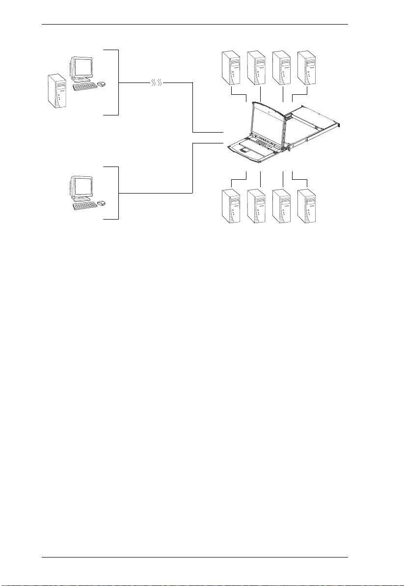
The KL1508Ai and KL1516Ai Dual Rail LCD KVM Switches are control
units that allow secure access to multiple computers from a single KVM
(keyboard, video, and mouse), console. A single KL1508Ai or KL1516Ai can
control up to 8 or 16 computers, respectively. They consist of an integrated
LED-backlit LCD monitor, keyboard, and touchpad in a 1U rack-mountable
retractable sliding housing.
The similarities and differences among the models in the KL1508Ai /
KL1516Ai series are shown in the following table:
Model LCD Panel Ports
KL1508AiM 17" 8
KL1508AiN 19" 8
KL1516AiM 17" 16
KL1516AiN 19" 16
The LCD and keyboard/touchpad modules slide independently of each other.
To maximize space in your data center, the keyboard/touchpad module slides
back to "hide away" when not in use, while the thin profile LCD monitor
rotates back – flush against the rack – allowing convenient monitoring of
computer activity.
The KL1508Ai / KL1516Ai features IP-based connectivity that allows one
local operator and multiple remote operators to concurrently monitor and
access the computers on your installation. Because it uses TCP/IP for its
communications protocol, the KL1508Ai / KL1516Ai can be accessed from
any computer on the LAN, WAN, or Internet – whether that computer is
located down the hall, down the street, or halfway around the world.
1
KL1508Ai / KL1516Ai User Manual
Local
Computer
Remote Computer
KL1508Ai/KL1516Ai
Internet
By daisy chaining up to 15 additional switches, as many as 256 computers can
be controlled from the original KVM console. An auto-sensing function
recognizes the position of each station on the chain, eliminating the need to
manually set the position, and a two digit seven-segment LED display on the
keyboard module showing each station's position for easy identificat ion.
Compact, high-density, RJ-45 connectors and CAT 5e/6 cable make for a
compact, efficient, wiring configuration, while the use of PS/2 and USB KVM
Adapter Cables to link to the computers, permits any combination of PCs,
Macs, Sun computers, and serial devices to coexist on the installation.
For added convenience, ports for an external keyboard, monitor, and mouse are
provided on the rear panel – permitting you to manage the switch from a local
console. There is also an external USB mouse port on the keyboard module,
allowing you to use an external mouse, rather than the touchpad.
Access to any computer connected to the installation from the local console is
easily accomplished by means of a powerful mouse driven graphical OSD (On
Screen Display) menu system. A convenient Auto Scan feature also permits
automatic scanning and monitoring of the activities of all computers running
on the installation one by one.
Remote operators connect to the KL1508Ai / KL1516Ai via its IP address from
anywhere on the LAN, WAN, or Internet via their browsers. Once they
successfully log in, they can take control using either the Windows Client or
Java Client utility. Inclusion of a Java-based client ensures that the KL1508Ai
2

Chapter 1. Introduction
/ KL1516Ai is platform independent, and is able to work with most operating
systems.
System administrators can handle a multitude of maintenance tasks smoothly
and efficiently – from installing and running GUI applications, to BIOS level
troubleshooting, routine monitoring, concurrent maintenance, system
administration, rebooting and even pre-booting functions – all from a remote
connection.
Remote operators can exchange keyboard, video and mouse signals with the
computers attached to the KL1508Ai / KL1516Ai just as if they were present
locally and working on the equipment directly.
Enhanced features include a Panel Array Mode that displays the video output
of up to 8 (KL1508Ai) or 16 (KL1516Ai) computers at the same time, and a
Message Board that allows logged in users to conveniently and instantly
communicate with one other – no matter where in the world they actually are.
Setup is fast and easy - plugging cables into their appropriate ports is all that is
entailed. Because the KL1508Ai / KL1516Ai intercepts keyboard input
directly, there is no need to get involved in complex installation routines or to
be concerned with incompatibility problems.
Since the KL1508Ai / KL1516Ai's firmware is upgradable over the Internet,
you can stay current with the latest functionality improvements simply by
downloading firmware updates from our website as they become available.
With its advanced security features, the KL1508Ai / KL1516Ai is the fastest,
most reliable, most cost effective way to remotely access and manage widely
distributed multiple computer installations.
3

KL1508Ai / KL1516Ai User Manual
Features
Hardware
Integrated KVM console with 17” or 19” LED-backlit LCD monitor in a
Dual Rail housing
Exclusive LED illumination light – designed by ATEN to illuminate the
keyboard and touchpad to allow visibility in low-light conditions
A single console controls up to 8 (KL1508Ai) or 16 (KL1516Ai)
computers
Daisy chain up to 15 additional KVM switches to control up to 256
computers*
One bus for remote KVM over IP access
Space-saving RJ-45 connectors and Cat 5e/6 cabling
KVM adapter cables designed with automatic conversion to allow flexible
interface combinations (PS/2, USB, Sun and serial) to control all computer
types
Extra console port – manage computers in the LCD KVM switch from an
external console (monitor, USB or PS/2 keyboard, and USB or PS/2
mouse)
Multiplatform support: PC, Mac, Sun and Serial
Supports external USB mouse
Dual Rail housing is slightly less than 1U with top and bottom clearance
for smooth operation in 1U of rack space
Dual Rail – LCD monitor slides independently of the keyboard/touchpad
LCD module rotates up to 120 degrees for a more comfortable viewing
angle
Console lock – enables the console drawer to remain securely locked away
in position when not in use
LCD power button helps save energy and prolong displays’ life
*Compatible KVM switches: KH1508A/KH1516A, KH0116, ACS1208A/
ACS1216A, CS1708A/CS1716A, KH1508/KH1516
Management
Up to 64 user accounts – up to 32 concurrent remote logins
End session feature – administrators can terminate any running session
4

Chapter 1. Introduction
Adapter ID – stores port information allowing administrators to relocate
servers to different ports, without having to reconfigure the adapters and
switch
Port Share Mode allows multiple users to gain access to a server
simultaneously
Remote power control for attached Power Over the NET™ devices
Integration with ALTUSEN CC2000 Management software
Event logging and Windows-based Log Server support
Local Log Event
Firmware upgradeable
IPv6 capable
Easy-to-Use Interface
Easy computer selection via pushbuttons, Hotkey Mode, OSD (On-Screen
Display), and Browser-based GUI
Local Console, Browser, and AP GUIs offer a unified multi language
interface to minimize user training time and increase productivity
Multiplatform client support (Windows, Mac OS X, Linux, Sun)
Multi-browser support: Internet Explorer, Chrome, Firefox, Safari, Opera,
Mozilla, Netscape
Browser-based UI in pure Web technology allows administrators to
perform administrative tasks without the need for Java to be pre-installed
Panel Array Mode™
Keyboard broadcast* – keyboard input can be duplicated on all the
attached servers
Keyboard Language support: English (US); English (UK); German;
German (Swiss); French; Spanish; Traditional Chinese; Japanese; Korean;
Swedish; Italian; Russian; Hungarian and Greek
*Local Console only
Advanced Security
Remote authentication support: RADIUS, LDAP , LDAPS, and MS Active
Directory
Supports TLS 1.2 encryption and RSA 1024-bit certificates to secure user
logins from browsers
5

KL1508Ai / KL1516Ai User Manual
Flexible encryption design allows users to choose any combination of 56-
bit DES, 168-bit 3DES 256-bit AES, 128-bit RC4, or Random for
independent KB/Mouse, and video data encryption
IP/MAC Filter support for enhanced security protection
Configurable user and group permissions for server access and control
Virtual Remote Desktop
Video qu ality and video t olerance can be adjusted to optimize data transfer
speed; monochrome color depth setting, threshold and noise settings for
compression of the data bandwidth in low bandwidth situations
Full-screen or sizable and scalable Virtual Remote Desktop
Message board feature allows logged in users to communicate with each
other
Mouse DynaSync™ – automatically synchronizes the local and remote
mouse movements
On-screen keyboard with multi language support
BIOS-level access
6

Chapter 1. Introduction
Requirements
General
We recommend computers with at least a P 4 2GHz processor, and 1 GB
RAM.
Browsers must support TLS 1.2 encryption.
A network transfer speed of at least 512kbps is recommended.
For the Log Server, you mus t have the Micros oft Jet O LEDB 4.0 or hi gher
driver installed.
External Console
A VGA, SVGA, or Multisync monitor capable of the highest resolution
that you will be using on any computer in the installation.
A USB or PS/2 style mouse
A USB or PS/2 style keyboard
Computers
The following equipment must be installed on the computers that connect to the
KL1508Ai or KL1516Ai's KVM ports:
A VGA, SVGA or Multisync port
A Type A USB port and USB host controller (for USB KVM Adapter
Cable Connection, see below)
6-pin mini-DIN keyboard and mouse ports (for PS/2 KVM Adapter Cable
Connection, see below)
Note: The integrated LCD monitor’s maximum screen resolution is 1280
x 1024 @ 75 Hz. If you want to use a higher setting for the screen
resolutions of the attached computers, see Screen Resolutions
Higher than 1280 x 1024, page 206.
KVM Adapter Cables
Cat 5e/6 cable is required to connect the KL1508Ai / KL1516Ai to one of the
KVM adapter cables.
7
KL1508Ai / KL1516Ai User Manual
The following KVM adapter cables are required for use with the KL1508Ai /
KL1516Ai:
Function Module
Connect to devices with PS/2 ports KA7920 / KA7520 / KA7120
Connect to devices with USB ports KA7970 / KA7570 / KA7166 /
Connect to Sun Legacy systems (with 13W3 port) KA9130 / KA7130
Connect to Sun USB systems KA9170 / KA7170
Connect to serial based device s KA9140
KA9520 / KA9120
KA7168 / KA7169 / KA7170
KA9570 / KA9170
Note: 1. KVM adapter cables are referred to as I/O Modules in some dialog boxes.
2. The following cable models support the Adapter Cable ID function:
KA7920 / KA7970 / KA7520 / KA7570 / KA7120 / KA7130 / KA7166
/ KA7168 / KA7169 / KA7170.
Operating Systems
Supported operating systems are shown in the table, below:
OS Version
Windows
2
Linux
UNIX IBM AIX4.3, 5L (V5.2,V5.3), V6 (V6.1)
Novell Netware 5.0 and higher
Sun Solaris 8, 9, 10
Mac 9.0, 9.1, 10.1, 10.2, 10. 3, 10.4 , 10.5
DOS
1
Does not support USB. 2 Kernels below 2.6 do not support USB 2.0
8
RedHat 9.0, Fedora and higher, RHEL AS 4, RHEL 5
SuSE 10 and higher, OpenSUSE 10.2; SLES 10 SP1
Debian 3.1, 4.0
Ubuntu 7.04, 7.10
FreeBSD 5.5, 6.1, 6.2
NT1, Server 2003, Server 2008, 2000 and higher
6.2 and higher
1
Chapter 1. Introduction
Components
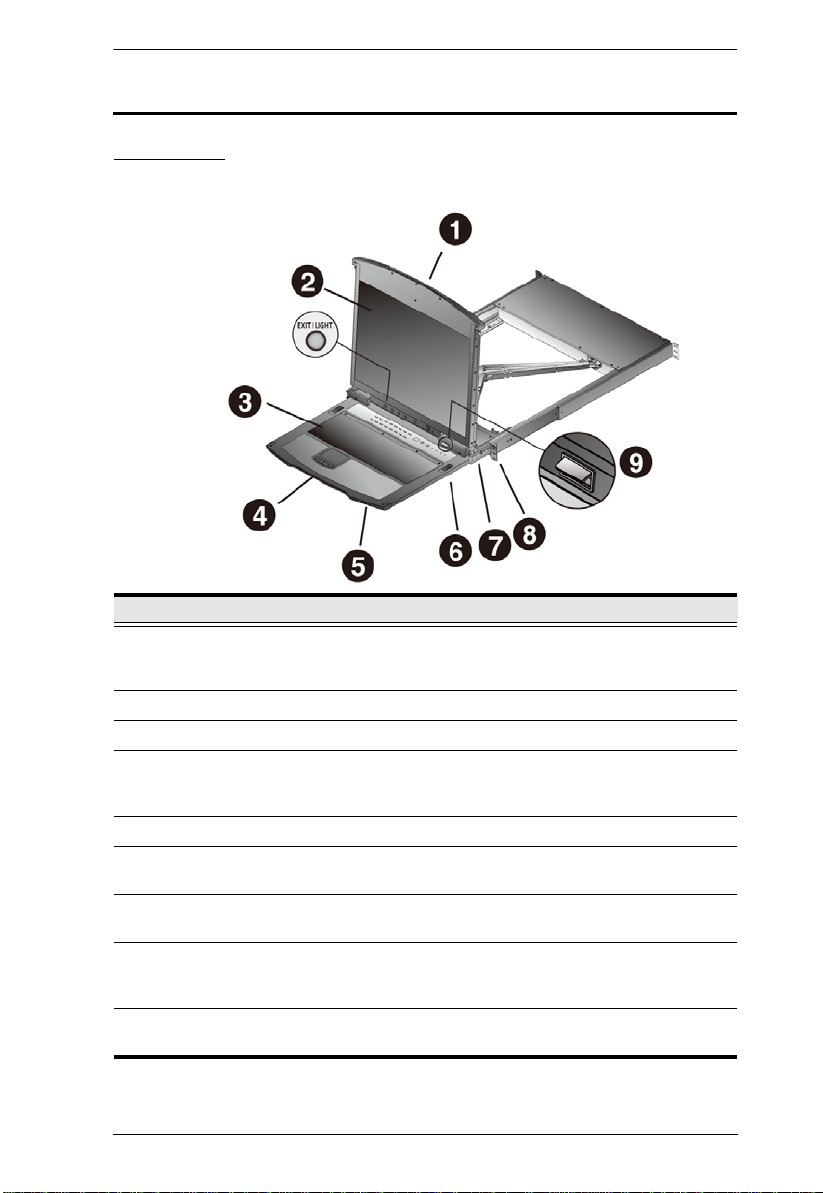
Front View
No. Component Description
1 Upper Handle Pull to slide the LCD module out; push to slide the module in.
2 LCD Module See LCD Module, page 11.
3 Keyboard Module See Keyboard Module, page 10.
4 Lower Handle Pull to slide the keyboard module out. See Opening the
5 Power LED Lights (blue) to indicate that the unit is receiving power.
6 Keyboard
Release Catch
7 LCD Release
Catch
8 Rack Mounting
Tabs
9 LED Illumination
Light
See Opening the Console, page 23, for details on sliding the
console in and out.
Console, page 23, for more details on sliding the console in
and out.
These catches (one on each side) release the keyboard
module so you can slide it away.
These catches (one on each side) release the LCD module
so you can slide it away.
The rack mounting tabs located at each corner of the unit
secure the chassis to a system rack. See Standard Rack
Mounting, page 14, for details.
Illuminates the keyboard and touchpad to allow visibility in
low-light conditions.
9
KL1508Ai / KL1516Ai User Manual
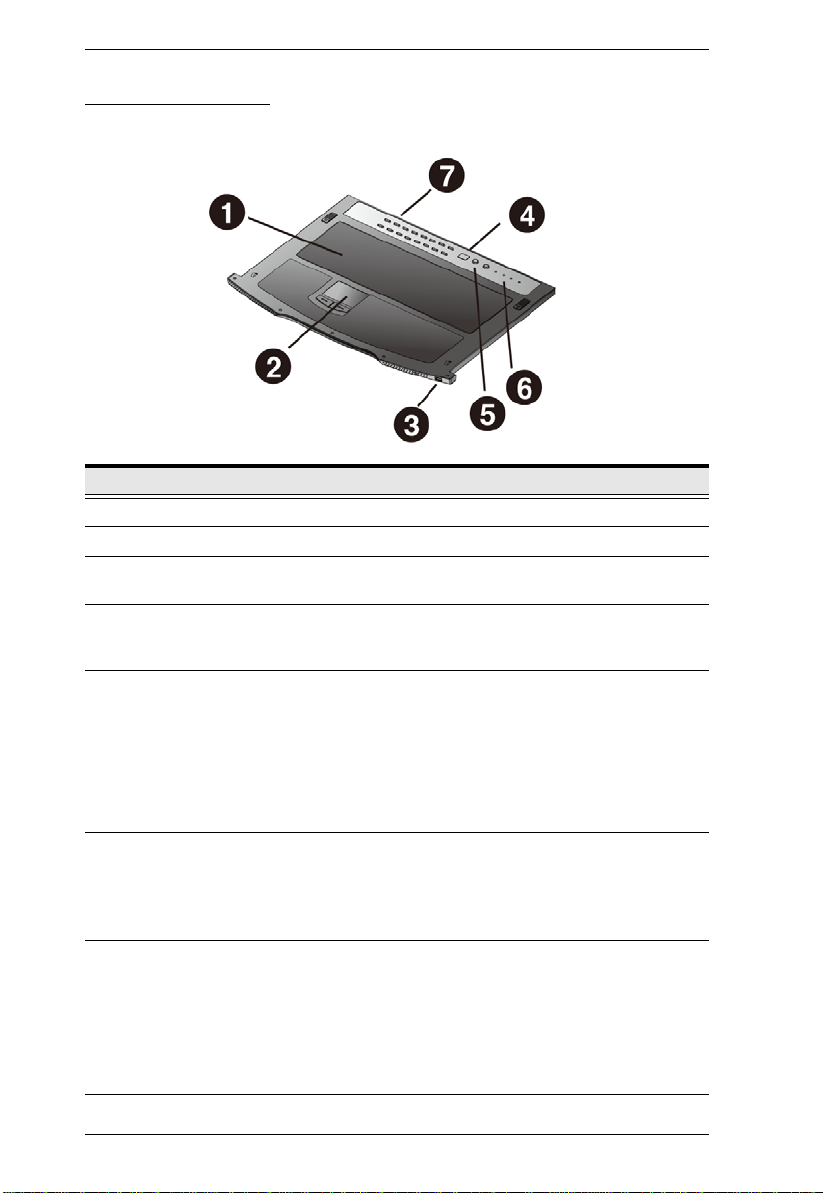
Keyboard Module
No. Component Description
1 Keyboard Standard 105-key keyboard
2 Touchpad Standard mouse touchpad
3 External Mouse
Port
4 Station ID LED In a daisy chained installation, the Station ID of the currently
5 Station Selection
Area
6 Lock LEDs &
Reset Switch
7 Port Selection
Buttons and
LEDs
This USB-type mouse port is provided for users who prefer to
use an external mouse.
selected station displays as a 2-digit figure in this
panel.See Port ID Numbering, page 33 for further details.
The LED displays the station number that the port with the
KVM focus is located on.
The left button shifts the KVM focus down the chain
(Station 2
to the last Station.
The right button shifts the KVM focus up the chain. After the
last Station, it cycles to Station 1.
The Num Lock, Caps Lock, Scroll Lock LEDs are located
here.
A Reset Switch is located just to the right of the Lock LEDs.
Press this recessed switch in with a thin object to perform a
system reset.
To access a Port on the currently selected Station press its
corresponding port selection button. Indicator LEDs are built
into the switches:
→ Station 1, etc.). After Station 1, it cycles back
An On Line LED lights to indicate that the computer
attached to its corresponding port is up and running.
A Selected LED lights to indicate which port has the KVM
focus.
10
Chapter 1. Introduction
LCD Module
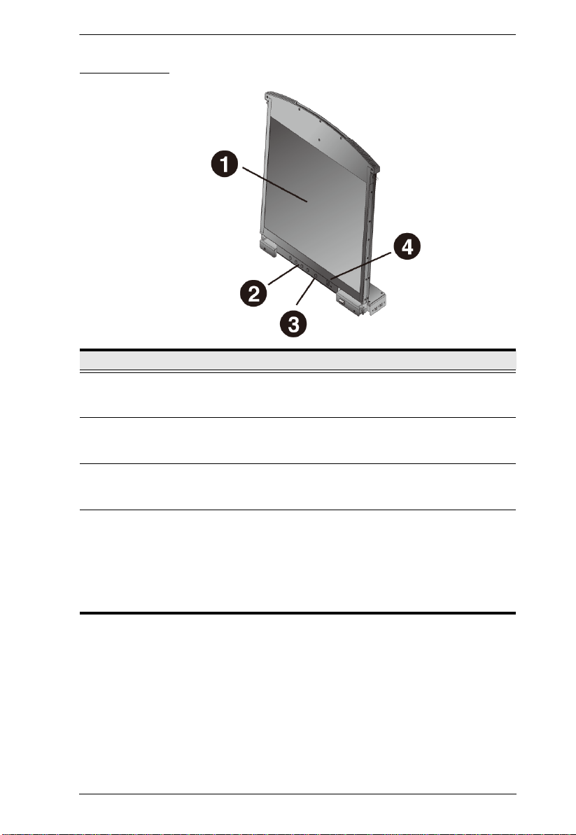
No. Component Description
1 LCD Display To access the LCD monitor, slide the LCD module out and flip
2 LCD Controls These buttons control the position and picture settings of the
3 LCD On/Off
Button
4 Firmware
Upgrade Section
up the cover. See Opening the Console, page 23, for details
on sliding the LCD module out.
LCD display. See LCD OSD Configuration, page 29, for
details.
Push this button to turn the LCD monitor on and off. The
button lights when the LCD monitor is off to indicate that only
the monitor is off – not the KVM switch itself.)
Firmware Upgrade Port: The Firmware Upgrade Cable that
transfers the firmware upgrade data from the administrator's
computer to the KL1508Ai / KL1516Ai
connector.
Firmware Upgrade Switch: During normal operation this
switch should be in the NORMAL position. (See The Firmware
Upgrade Utility, page159 for firmware upgrading details.)
plugs into this RJ-11
11
KL1508Ai / KL1516Ai User Manual
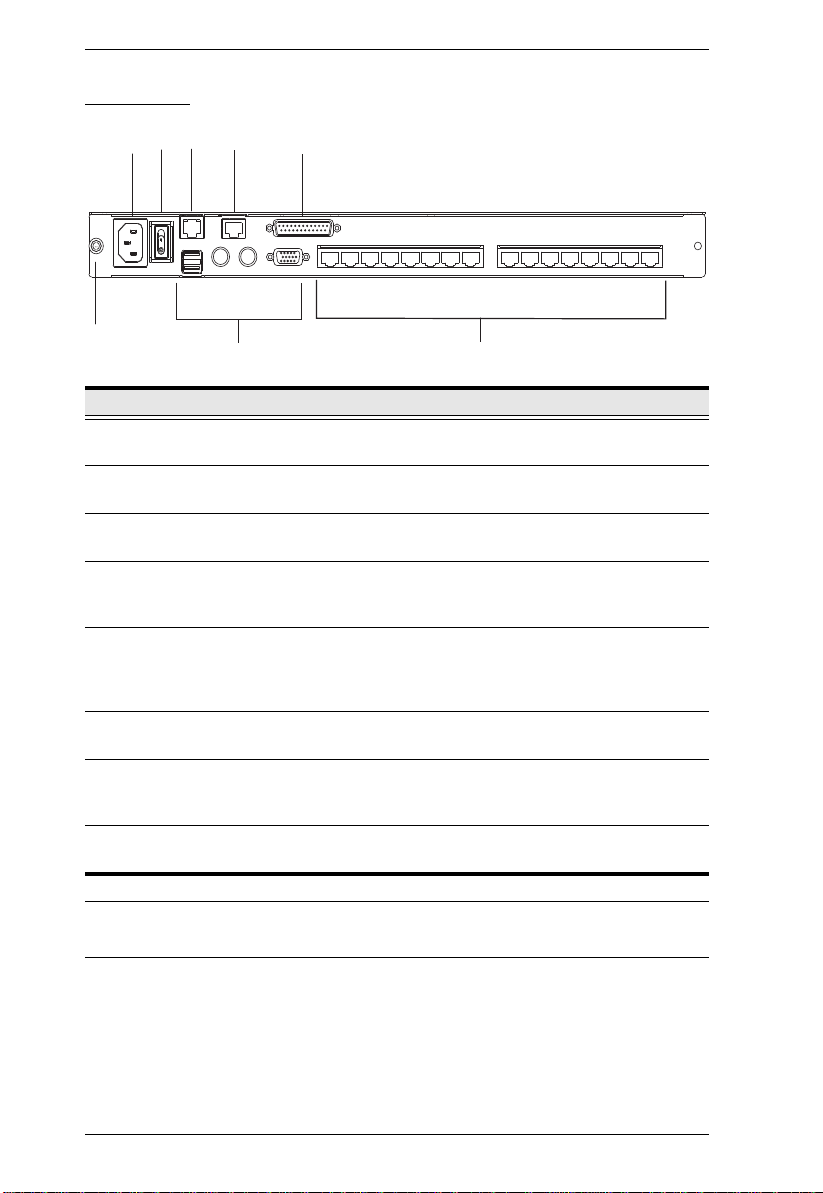
Rear View
3
2
4
5
6
1
No. Component Description
1 Grounding
Terminal
2 Power Socket This is a standard 3-pin AC power socket. The power cord
3 Power Switch This is a standard rocker switch that powers the unit on and
4 LAN Port The cable that connects the to the LAN plugs in here. The
5 PON Port This connector is provided for a Power over the Net™ (PON)
6 Daisy Chain Port When Daisy Chaining Units (See Daisy Chaining, page 20),
7 Local Console
Port Selection
8 KVM Port
Selection
7
The grounding wire used to ground the switch attaches here.
from an AC source plugs in here.
off.
LEDs indicate data transmission speed: ORANGE: 10 Mbps /
GREEN: 100 Mbps
unit to plug into. A PON device allows computers attached to
the KL1508Ai / KL1516Ai to be booted remotely over the net.
Contact your dealer for more details.
the daisy chain cable plugs in here.
If this is a Single Station installation, or if this is the First
Station of a daisy chained installation, the keyboard, monitor,
and the mouse that make up the Local Console plug in here.
The Cat 5e/6 cables that link to the KVM Adapter Cables
(which link to the computers) plug in here.
8
* The KL1516Ai is pictured above. The KL1508Ai rear panel is the same as
that of the KL1516Ai, except that it has 8 KVM ports instead of 16.
12
Hardware Setup
1. Important safety information regarding the placement of this
device is provided on page 187. Please review it before
proceeding.
2. Make sure that power to all the devices you will be connecting
up has been turned off. You must unplug the power cords of any
computers that have the Keyboard Power On function.
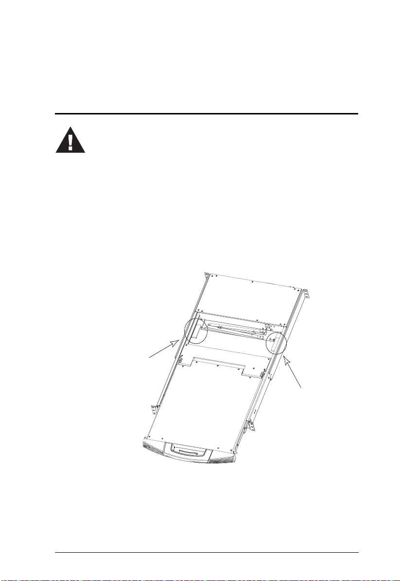
3. Packing material has been inserted to protect the KL1508Ai /
KL1516Ai during shipping. Slide the LCD module out (see
Opening the Console, page 23), until the packing material is
visible. Remove the packing material before installing the unit,
as shown in the diagram below.
Before You Begin
Chapter 2
13
KL1508Ai / KL1516Ai User Manual
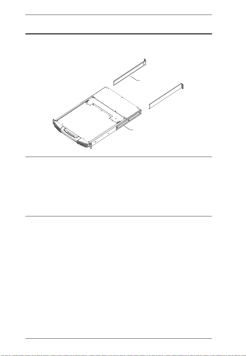
L Brackets
Side Mountng
Brackets
Standard Rack Mounting
A standard rack mounting kit is provided with your KL1508Ai / KL1516Ai.
The kit enables the switch to be mounted in a rack with a depth of 42–77 cm.
Note: 1. It takes two people to mount the switch: one to hold it in place, the
other to screw it in.
2. The standard rack mounting kit does not include screws or cage nuts.
If you need additional screws or cage nuts, contact your rack dealer.
3. Optional mounting kits – incl udi ng single person Easy Installation
kits – are available with a separate purchase. See Optional Rack
Mounting, page 213, for details.
14
 Loading...