


Dual Rail LCD KVM Switch
KL1508Ai / KL1516Ai
Full HD Version
User Manual
www.aten.com

KL1508Ai / KL1516Ai User Manual
EMC Information
FEDERAL COMMUNICATIONS COMMISSION INTERFERENCE
STATEMENT: This equipment has been tested and found to comply with the
limits for a Class A digital device, pursuant to Part 15 of the FCC Rules. These
limits are designed to provide reasonable protection against harmful
interference when the equipment is operated in a commercial environment.
This equipment generates, uses, and can radiate radio frequency energy and, if
not installed and used in accordance with the instruction manual, may cause
harmful interference to radio communications. Operation of this equipment in
a residential area is likely to cause harmful interference in which case the user
will be required to correct the interference at his own expense.
The device complies with Part 15 of the FCC Rules. Operation is subject to the
following two conditions: (1) this device may not cause harmful interference,
and (2) this device must accept any interference received, including
interference that may cause undesired operation.
FCC Caution: Any changes or modifications not expressly approved by the
party responsible for compliance could void the user's authority to operate this
equipment.
Warning: Operation of this equipment in a residential environment cold cause
radio interference.
Achtung: Der Gebrauch dieses Geräts in Wohnumgebung kann
Funkstörungen verursachen.
Suggestion: Shielded twisted pair (STP) cables must be used with the unit to
ensure compliance with FCC & CE standards.
KCC Statement
RoHS
This product is RoHS compliant.
© Copyright 2021 ATEN® International Co., Ltd.
ATEN and the ATEN logo are registered trademarks of ATEN International Co., Ltd. All rights reserved.
All other brand names and trademarks are the registered property of their respective owners.
ii
Manual Date: 2021-01-05

KL1508Ai / KL1516Ai User Manual
User Information
Online Registration
Be sure to register your product at our online support center:
International http://eservice.aten.com
Telephone Support
For telephone support, call this number:
International 886-2-8692-6959
China 86-400-810-0-810
Japan 81-3-5615-5811
Korea 82-2-467-6789
North America 1-888-999-ATEN ext 4988
1- 949-4 28-1111
iii

KL1508Ai / KL1516Ai User Manual
User Notice
All information, documentation, and specifications contained in this manual
are subject to change without prior notification by the manufacturer. The
manufacturer makes no representations or warranties, either expressed or
implied, with respect to the contents hereof and specifically disclaims any
warranties as to merchantability or fitness for any particular purpose. Any of
the manufacturer's software described in this manual is sold or licensed `as is'.
Should the programs prove defective following their purchase, the buyer (and
not the manufacturer, its distributor, or its dealer), assumes the entire cost of all
necessary servicing, repair and any incidental or consequential damages
resulting from any defect in the software.
The manufacturer of this system is not responsible for any radio and/or TV
interference caused by unauthorized modifications to this device. It is the
responsibility of the user to correct such interference.
The manufacturer is not responsible for any damage incurred in the operation
of this system if the correct operational voltage setting was not selected prior
to operation. PLEASE VERIFY THAT THE VOLTAGE SETTING IS
CORRECT BEFORE USE.
A typical LCD (Liquid Crystal Display) monitor has millions of pixels. A dead
pixel refers to a pixel with a defect in its ability to display the correct color
output. It most often looks like a tiny black or white spot on your screen,
although it can be any other color. Since even a tiny dust particle on one of the
pixels during the manufacturing process or a slight bump during shipping can
create a dead pixel, the ISO 13406-2 norm defines 4 classes of acceptable
screens with dead pixels--Class 1 is the best; Class 4 is the worst. Almost all
manufacturers use Class 2 to establish their warranties, which allows a certain
amount of dead pixels to exist before they will replace the screen. Since the
manufacturers consider these screens to be acceptable under ISO
specifications, we cannot be responsible for replacement or warranty of the
TFT LCD panel.
iv

KL1508Ai / KL1516Ai User Manual
Package Contents
Basic Package
The basic KL1508Ai / KL1516Ai package consists of:
1 KL1508Ai or KL1516Ai Dual Rail LCD KVM Switch
1 Power Cord
1 Standard Rack Mount Kit
1 Firmware Upgrade Cable
1 User Instructions*
Check to make sure that all of the components are present and in good order.
If anything is missing, or was damaged in shipping, contact your dealer.
Read this manual thoroughly and follow the installation and operation
procedures carefully to prevent any damage to the switch or to any other
devices on the KL1508Ai / KL1516Ai installation.
* Changes may have been made to the manual since it was published. Please
visit our Website to check for the most up-to-date version.
v

KL1508Ai / KL1516Ai User Manual
Contents
EMC Information. . . . . . . . . . . . . . . . . . . . . . . . . . . . . . . . . . . . . . . . . . . . . ii
RoHS . . . . . . . . . . . . . . . . . . . . . . . . . . . . . . . . . . . . . . . . . . . . . . . . . . . . . ii
User Information . . . . . . . . . . . . . . . . . . . . . . . . . . . . . . . . . . . . . . . . . . . . . iii
Online Registration . . . . . . . . . . . . . . . . . . . . . . . . . . . . . . . . . . . . . . . .iii
Telephone Support . . . . . . . . . . . . . . . . . . . . . . . . . . . . . . . . . . . . . . . .iii
User Notice . . . . . . . . . . . . . . . . . . . . . . . . . . . . . . . . . . . . . . . . . . . . . .iv
Package Contents . . . . . . . . . . . . . . . . . . . . . . . . . . . . . . . . . . . . . . . . . . . v
Basic Package . . . . . . . . . . . . . . . . . . . . . . . . . . . . . . . . . . . . . . . . . . . v
About This Manual . . . . . . . . . . . . . . . . . . . . . . . . . . . . . . . . . . . . . . . . . . xiii
Conventions . . . . . . . . . . . . . . . . . . . . . . . . . . . . . . . . . . . . . . . . . . . . xv
Product Information . . . . . . . . . . . . . . . . . . . . . . . . . . . . . . . . . . . . . . . . . xv
Chapter 1.
Introduction
Overview. . . . . . . . . . . . . . . . . . . . . . . . . . . . . . . . . . . . . . . . . . . . . . . . . . . 1
Features . . . . . . . . . . . . . . . . . . . . . . . . . . . . . . . . . . . . . . . . . . . . . . . . . . . 4
Hardware. . . . . . . . . . . . . . . . . . . . . . . . . . . . . . . . . . . . . . . . . . . . . . . . 4
Management . . . . . . . . . . . . . . . . . . . . . . . . . . . . . . . . . . . . . . . . . . . . . 5
Easy-to-Use Interface . . . . . . . . . . . . . . . . . . . . . . . . . . . . . . . . . . . . . . 5
Advanced Security . . . . . . . . . . . . . . . . . . . . . . . . . . . . . . . . . . . . . . . . 6
Virtual Remote Desktop . . . . . . . . . . . . . . . . . . . . . . . . . . . . . . . . . . . . 6
Requirements . . . . . . . . . . . . . . . . . . . . . . . . . . . . . . . . . . . . . . . . . . . . . . . 7
General . . . . . . . . . . . . . . . . . . . . . . . . . . . . . . . . . . . . . . . . . . . . . . . . . 7
External Console. . . . . . . . . . . . . . . . . . . . . . . . . . . . . . . . . . . . . . . . . . 7
Computers. . . . . . . . . . . . . . . . . . . . . . . . . . . . . . . . . . . . . . . . . . . . . . . 7
KVM Adapter Cables. . . . . . . . . . . . . . . . . . . . . . . . . . . . . . . . . . . . . . . 7
Adapter Cable Resolutions . . . . . . . . . . . . . . . . . . . . . . . . . . . . . . . . . . 8
Operating Systems . . . . . . . . . . . . . . . . . . . . . . . . . . . . . . . . . . . . . . . . 9
Components . . . . . . . . . . . . . . . . . . . . . . . . . . . . . . . . . . . . . . . . . . . . . . . 10
Front View. . . . . . . . . . . . . . . . . . . . . . . . . . . . . . . . . . . . . . . . . . . . . . 10
Keyboard Module . . . . . . . . . . . . . . . . . . . . . . . . . . . . . . . . . . . . . . . . 11
LCD Module . . . . . . . . . . . . . . . . . . . . . . . . . . . . . . . . . . . . . . . . . . . . 12
Rear View . . . . . . . . . . . . . . . . . . . . . . . . . . . . . . . . . . . . . . . . . . . . . . 13
Chapter 2.
Hardware Setup
Before You Begin . . . . . . . . . . . . . . . . . . . . . . . . . . . . . . . . . . . . . . . . . . . 15
Standard Rack Mounting . . . . . . . . . . . . . . . . . . . . . . . . . . . . . . . . . . . . . 16
Front-L Brackets Mounting . . . . . . . . . . . . . . . . . . . . . . . . . . . . . . . . . . . . 18
Optional Rack Mount Kits . . . . . . . . . . . . . . . . . . . . . . . . . . . . . . . . . . . . . 20
Single Stage Installation . . . . . . . . . . . . . . . . . . . . . . . . . . . . . . . . . . . . . . 21
Daisy Chaining . . . . . . . . . . . . . . . . . . . . . . . . . . . . . . . . . . . . . . . . . . . . . 25
Chapter 3.
Basic Operation
vi

KL1508Ai / KL1516Ai User Manual
Opening the Console . . . . . . . . . . . . . . . . . . . . . . . . . . . . . . . . . . . . . . . . 27
Opening Separately. . . . . . . . . . . . . . . . . . . . . . . . . . . . . . . . . . . . . . .27
Opening Together . . . . . . . . . . . . . . . . . . . . . . . . . . . . . . . . . . . . . . . .29
Operating Precautions . . . . . . . . . . . . . . . . . . . . . . . . . . . . . . . . . . . .30
Closing the Console . . . . . . . . . . . . . . . . . . . . . . . . . . . . . . . . . . . . . . . . .31
LCD OSD Configuration . . . . . . . . . . . . . . . . . . . . . . . . . . . . . . . . . . . . . . 33
The LCD Buttons. . . . . . . . . . . . . . . . . . . . . . . . . . . . . . . . . . . . . . . . .33
The Adjustment Settings . . . . . . . . . . . . . . . . . . . . . . . . . . . . . . . . . . .34
Port Selection . . . . . . . . . . . . . . . . . . . . . . . . . . . . . . . . . . . . . . . . . . . . . .35
Manual. . . . . . . . . . . . . . . . . . . . . . . . . . . . . . . . . . . . . . . . . . . . . . . . .35
OSD / GUI . . . . . . . . . . . . . . . . . . . . . . . . . . . . . . . . . . . . . . . . . . . . . .35
Hotkeys . . . . . . . . . . . . . . . . . . . . . . . . . . . . . . . . . . . . . . . . . . . . . . . .35
Hot Plugging . . . . . . . . . . . . . . . . . . . . . . . . . . . . . . . . . . . . . . . . . . . . . . .36
Hot Plugging Stations . . . . . . . . . . . . . . . . . . . . . . . . . . . . . . . . . . . . .36
Hot Plugging KVM Ports . . . . . . . . . . . . . . . . . . . . . . . . . . . . . . . . . . .36
Hot Plugging Console Ports . . . . . . . . . . . . . . . . . . . . . . . . . . . . . . . .36
Powering Off and Restarting. . . . . . . . . . . . . . . . . . . . . . . . . . . . . . . . . . .37
Port ID Numbering . . . . . . . . . . . . . . . . . . . . . . . . . . . . . . . . . . . . . . . . . .37
Chapter 4.
OSD Operation
OSD Overview . . . . . . . . . . . . . . . . . . . . . . . . . . . . . . . . . . . . . . . . . . . . .39
Manufacturing Number . . . . . . . . . . . . . . . . . . . . . . . . . . . . . . . . . . . .40
OSD Navigation . . . . . . . . . . . . . . . . . . . . . . . . . . . . . . . . . . . . . . . . . . . .41
OSD Main Screen Headings. . . . . . . . . . . . . . . . . . . . . . . . . . . . . . . . . . .41
OSD Functions . . . . . . . . . . . . . . . . . . . . . . . . . . . . . . . . . . . . . . . . . . . . .42
F1: GOTO . . . . . . . . . . . . . . . . . . . . . . . . . . . . . . . . . . . . . . . . . . . . . .42
F2: LIST. . . . . . . . . . . . . . . . . . . . . . . . . . . . . . . . . . . . . . . . . . . . . . . .43
F3: SET . . . . . . . . . . . . . . . . . . . . . . . . . . . . . . . . . . . . . . . . . . . . . . . .44
F4: ADM . . . . . . . . . . . . . . . . . . . . . . . . . . . . . . . . . . . . . . . . . . . . . . .47
F5: SKP . . . . . . . . . . . . . . . . . . . . . . . . . . . . . . . . . . . . . . . . . . . . . . . .50
F6: BRC. . . . . . . . . . . . . . . . . . . . . . . . . . . . . . . . . . . . . . . . . . . . . . . .51
F7: SCAN . . . . . . . . . . . . . . . . . . . . . . . . . . . . . . . . . . . . . . . . . . . . . . 52
F8: LOUT. . . . . . . . . . . . . . . . . . . . . . . . . . . . . . . . . . . . . . . . . . . . . . .53
Chapter 5.
Hotkey Operation
Hotkey Port Control. . . . . . . . . . . . . . . . . . . . . . . . . . . . . . . . . . . . . . . . . .55
Invoking Hotkey Mode. . . . . . . . . . . . . . . . . . . . . . . . . . . . . . . . . . . . . . . . 56
Selecting the Active Port. . . . . . . . . . . . . . . . . . . . . . . . . . . . . . . . . . . . . . 57
Auto Scan Mode Switching. . . . . . . . . . . . . . . . . . . . . . . . . . . . . . . . . . . . 58
Skip Mode Switching. . . . . . . . . . . . . . . . . . . . . . . . . . . . . . . . . . . . . . . . .60
Computer Keyboard / Mouse Reset . . . . . . . . . . . . . . . . . . . . . . . . . . . . .61
Setting the Hotkey Beeper ON/OFF . . . . . . . . . . . . . . . . . . . . . . . . . . . . . 61
Setting the Hotkey key combination . . . . . . . . . . . . . . . . . . . . . . . . . . . . .62
Setting the OSD Hotkey combination . . . . . . . . . . . . . . . . . . . . . . . . . . . . 62
Setting the Port Operating System . . . . . . . . . . . . . . . . . . . . . . . . . . . . . . 63
vii

KL1508Ai / KL1516Ai User Manual
Restore the Default Values. . . . . . . . . . . . . . . . . . . . . . . . . . . . . . . . . . . . 63
Hotkey Summary Table . . . . . . . . . . . . . . . . . . . . . . . . . . . . . . . . . . . . . . 64
Chapter 6.
Keyboard Emulation
Mac Keyboard. . . . . . . . . . . . . . . . . . . . . . . . . . . . . . . . . . . . . . . . . . . . . . 65
Sun Keyboard. . . . . . . . . . . . . . . . . . . . . . . . . . . . . . . . . . . . . . . . . . . . . . 66
Chapter 7.
Logging In
Overview. . . . . . . . . . . . . . . . . . . . . . . . . . . . . . . . . . . . . . . . . . . . . . . . . . 67
Local Login . . . . . . . . . . . . . . . . . . . . . . . . . . . . . . . . . . . . . . . . . . . . . . . . 68
Browser Login. . . . . . . . . . . . . . . . . . . . . . . . . . . . . . . . . . . . . . . . . . . . . . 69
Windows Client AP Login . . . . . . . . . . . . . . . . . . . . . . . . . . . . . . . . . . . . . 70
The Windows Client AP Connection Screen. . . . . . . . . . . . . . . . . . . . 71
Connecting – Windows Client AP . . . . . . . . . . . . . . . . . . . . . . . . . . . . 72
Java Client AP Login . . . . . . . . . . . . . . . . . . . . . . . . . . . . . . . . . . . . . . . . 73
The Java Client AP Connection Screen . . . . . . . . . . . . . . . . . . . . . . . 74
Connecting – Java Client AP . . . . . . . . . . . . . . . . . . . . . . . . . . . . . . . 75
Chapter 8.
The User Interface
Overview. . . . . . . . . . . . . . . . . . . . . . . . . . . . . . . . . . . . . . . . . . . . . . . . . . 77
The Web Browser Main Page. . . . . . . . . . . . . . . . . . . . . . . . . . . . . . . . . . 77
Page Components . . . . . . . . . . . . . . . . . . . . . . . . . . . . . . . . . . . . . . . 78
The Tab Bar . . . . . . . . . . . . . . . . . . . . . . . . . . . . . . . . . . . . . . . . . . . . 79
The AP GUI Main Page . . . . . . . . . . . . . . . . . . . . . . . . . . . . . . . . . . . . . . 80
The Control Panel. . . . . . . . . . . . . . . . . . . . . . . . . . . . . . . . . . . . . . . . . . . 81
WinClient Control Panel . . . . . . . . . . . . . . . . . . . . . . . . . . . . . . . . . . . 81
WinClient Control Panel Functions . . . . . . . . . . . . . . . . . . . . . . . . . . . 83
Macros . . . . . . . . . . . . . . . . . . . . . . . . . . . . . . . . . . . . . . . . . . . . . . . . 86
Video Settings. . . . . . . . . . . . . . . . . . . . . . . . . . . . . . . . . . . . . . . . . . . 95
The Message Board . . . . . . . . . . . . . . . . . . . . . . . . . . . . . . . . . . . . . . 98
Zoom. . . . . . . . . . . . . . . . . . . . . . . . . . . . . . . . . . . . . . . . . . . . . . . . . 101
The On-Screen Keyboard. . . . . . . . . . . . . . . . . . . . . . . . . . . . . . . . . 102
Mouse Pointer Type . . . . . . . . . . . . . . . . . . . . . . . . . . . . . . . . . . . . . 104
Mouse DynaSync Mode . . . . . . . . . . . . . . . . . . . . . . . . . . . . . . . . . . 105
Control Panel Configuration . . . . . . . . . . . . . . . . . . . . . . . . . . . . . . . 107
The Java Control Panel. . . . . . . . . . . . . . . . . . . . . . . . . . . . . . . . . . . 109
Chapter 9.
Port Access
Overview. . . . . . . . . . . . . . . . . . . . . . . . . . . . . . . . . . . . . . . . . . . . . . . . . 111
Browser GUI . . . . . . . . . . . . . . . . . . . . . . . . . . . . . . . . . . . . . . . . . . . 111
AP GUI . . . . . . . . . . . . . . . . . . . . . . . . . . . . . . . . . . . . . . . . . . . . . . . 111
The Sidebar . . . . . . . . . . . . . . . . . . . . . . . . . . . . . . . . . . . . . . . . . . . . . . 113
The Sidebar Tree Structure. . . . . . . . . . . . . . . . . . . . . . . . . . . . . . . . 113
viii

KL1508Ai / KL1516Ai User Manual
Scan . . . . . . . . . . . . . . . . . . . . . . . . . . . . . . . . . . . . . . . . . . . . . . . . .114
Array Mode . . . . . . . . . . . . . . . . . . . . . . . . . . . . . . . . . . . . . . . . . . . .114
Filter . . . . . . . . . . . . . . . . . . . . . . . . . . . . . . . . . . . . . . . . . . . . . . . . .114
Connections . . . . . . . . . . . . . . . . . . . . . . . . . . . . . . . . . . . . . . . . . . . . . .116
Device Level . . . . . . . . . . . . . . . . . . . . . . . . . . . . . . . . . . . . . . . . . . . 116
Port Level . . . . . . . . . . . . . . . . . . . . . . . . . . . . . . . . . . . . . . . . . . . . .117
Favorites . . . . . . . . . . . . . . . . . . . . . . . . . . . . . . . . . . . . . . . . . . . . . . . . .118
User Preferences . . . . . . . . . . . . . . . . . . . . . . . . . . . . . . . . . . . . . . . . . . 120
Sessions . . . . . . . . . . . . . . . . . . . . . . . . . . . . . . . . . . . . . . . . . . . . . . . . .122
Access. . . . . . . . . . . . . . . . . . . . . . . . . . . . . . . . . . . . . . . . . . . . . . . . . . .123
Browser GUI Interface. . . . . . . . . . . . . . . . . . . . . . . . . . . . . . . . . . . .123
AP GUI Interface . . . . . . . . . . . . . . . . . . . . . . . . . . . . . . . . . . . . . . . .125
Saving Changes . . . . . . . . . . . . . . . . . . . . . . . . . . . . . . . . . . . . . . . .125
Port Configuration . . . . . . . . . . . . . . . . . . . . . . . . . . . . . . . . . . . . . . . . . .126
Associated Link . . . . . . . . . . . . . . . . . . . . . . . . . . . . . . . . . . . . . . . . .128
Occupy Timeout . . . . . . . . . . . . . . . . . . . . . . . . . . . . . . . . . . . . . . . .129
Chapter 10.
User Management
Overview . . . . . . . . . . . . . . . . . . . . . . . . . . . . . . . . . . . . . . . . . . . . . . . . . 131
Browser GUI . . . . . . . . . . . . . . . . . . . . . . . . . . . . . . . . . . . . . . . . . . .131
AP GUI . . . . . . . . . . . . . . . . . . . . . . . . . . . . . . . . . . . . . . . . . . . . . . .131
Users. . . . . . . . . . . . . . . . . . . . . . . . . . . . . . . . . . . . . . . . . . . . . . . . . . . .132
Adding Users. . . . . . . . . . . . . . . . . . . . . . . . . . . . . . . . . . . . . . . . . . . 132
Modifying User Accounts. . . . . . . . . . . . . . . . . . . . . . . . . . . . . . . . . .136
Deleting User Accounts. . . . . . . . . . . . . . . . . . . . . . . . . . . . . . . . . . .136
Device Assignment . . . . . . . . . . . . . . . . . . . . . . . . . . . . . . . . . . . . . . . . .137
Assigning Device Permissions From the User’s Notebook . . . . . . . .137
Chapter 11.
Device Management
KVM Devices. . . . . . . . . . . . . . . . . . . . . . . . . . . . . . . . . . . . . . . . . . . . . . 139
Device Information . . . . . . . . . . . . . . . . . . . . . . . . . . . . . . . . . . . . . .139
Operating Mode. . . . . . . . . . . . . . . . . . . . . . . . . . . . . . . . . . . . . . . . .141
Network . . . . . . . . . . . . . . . . . . . . . . . . . . . . . . . . . . . . . . . . . . . . . . .142
ANMS . . . . . . . . . . . . . . . . . . . . . . . . . . . . . . . . . . . . . . . . . . . . . . . .146
Security . . . . . . . . . . . . . . . . . . . . . . . . . . . . . . . . . . . . . . . . . . . . . . .150
Date/Time . . . . . . . . . . . . . . . . . . . . . . . . . . . . . . . . . . . . . . . . . . . . .161
Chapter 12.
Log
Overview . . . . . . . . . . . . . . . . . . . . . . . . . . . . . . . . . . . . . . . . . . . . . . . . . 163
Browser GUI . . . . . . . . . . . . . . . . . . . . . . . . . . . . . . . . . . . . . . . . . . .163
AP GUI . . . . . . . . . . . . . . . . . . . . . . . . . . . . . . . . . . . . . . . . . . . . . . .163
Log Information . . . . . . . . . . . . . . . . . . . . . . . . . . . . . . . . . . . . . . . . . . . .164
Chapter 13.
ix

KL1508Ai / KL1516Ai User Manual
Maintenance
Overview. . . . . . . . . . . . . . . . . . . . . . . . . . . . . . . . . . . . . . . . . . . . . . . . . 165
Browser GUI . . . . . . . . . . . . . . . . . . . . . . . . . . . . . . . . . . . . . . . . . . . 165
AP GUI . . . . . . . . . . . . . . . . . . . . . . . . . . . . . . . . . . . . . . . . . . . . . . . 165
Device IP Card Firmware Upgrade. . . . . . . . . . . . . . . . . . . . . . . . . . . . . 166
Mainboard and KVM Adapter Cable Firmware Upgrade . . . . . . . . . . . . 167
Mainboard Firmware Upgrade . . . . . . . . . . . . . . . . . . . . . . . . . . . . . 167
KVM Adapter Cable Firmware Upgrade . . . . . . . . . . . . . . . . . . . . . . 168
Station/Adapter Firmware Info . . . . . . . . . . . . . . . . . . . . . . . . . . . . . 169
Recovering from Failed Firmware Upgrade . . . . . . . . . . . . . . . . . . . . . . 170
Station (mainboard) and Adapter Firmware . . . . . . . . . . . . . . . . . . . 170
Backup/Restore . . . . . . . . . . . . . . . . . . . . . . . . . . . . . . . . . . . . . . . . . . . 171
Backup . . . . . . . . . . . . . . . . . . . . . . . . . . . . . . . . . . . . . . . . . . . . . . . 171
Restore . . . . . . . . . . . . . . . . . . . . . . . . . . . . . . . . . . . . . . . . . . . . . . . 172
Ping Host . . . . . . . . . . . . . . . . . . . . . . . . . . . . . . . . . . . . . . . . . . . . . . . . 173
System Operation. . . . . . . . . . . . . . . . . . . . . . . . . . . . . . . . . . . . . . . . . . 174
Clear Port Names:. . . . . . . . . . . . . . . . . . . . . . . . . . . . . . . . . . . . . . . 174
Reset Default Values: . . . . . . . . . . . . . . . . . . . . . . . . . . . . . . . . . . . . 174
Apply: . . . . . . . . . . . . . . . . . . . . . . . . . . . . . . . . . . . . . . . . . . . . . . . . 174
Chapter 14.
Download
Overview. . . . . . . . . . . . . . . . . . . . . . . . . . . . . . . . . . . . . . . . . . . . . . . . . 175
Chapter 15.
Port Operation
Overview. . . . . . . . . . . . . . . . . . . . . . . . . . . . . . . . . . . . . . . . . . . . . . . . . 177
Connecting to a Port. . . . . . . . . . . . . . . . . . . . . . . . . . . . . . . . . . . . . . . . 178
The Port Toolbar. . . . . . . . . . . . . . . . . . . . . . . . . . . . . . . . . . . . . . . . . . . 179
The Toolbar Icons . . . . . . . . . . . . . . . . . . . . . . . . . . . . . . . . . . . . . . . 180
Toolbar Hotkey Port Switching . . . . . . . . . . . . . . . . . . . . . . . . . . . . . 181
Recalling the Port Access Page . . . . . . . . . . . . . . . . . . . . . . . . . . . . 183
GUI Hotkey Summary Table. . . . . . . . . . . . . . . . . . . . . . . . . . . . . . . 183
Panel Array Mode. . . . . . . . . . . . . . . . . . . . . . . . . . . . . . . . . . . . . . . . . . 184
Panel Array Toolbar . . . . . . . . . . . . . . . . . . . . . . . . . . . . . . . . . . . . . 185
Multiuser Operation . . . . . . . . . . . . . . . . . . . . . . . . . . . . . . . . . . . . . . . . 186
Chapter 16.
The Log Server
Installation. . . . . . . . . . . . . . . . . . . . . . . . . . . . . . . . . . . . . . . . . . . . . . . . 187
Starting Up . . . . . . . . . . . . . . . . . . . . . . . . . . . . . . . . . . . . . . . . . . . . . . . 188
The Menu Bar. . . . . . . . . . . . . . . . . . . . . . . . . . . . . . . . . . . . . . . . . . . . . 189
Configure. . . . . . . . . . . . . . . . . . . . . . . . . . . . . . . . . . . . . . . . . . . . . . 189
Events . . . . . . . . . . . . . . . . . . . . . . . . . . . . . . . . . . . . . . . . . . . . . . . . 190
Options . . . . . . . . . . . . . . . . . . . . . . . . . . . . . . . . . . . . . . . . . . . . . . . 192
Help. . . . . . . . . . . . . . . . . . . . . . . . . . . . . . . . . . . . . . . . . . . . . . . . . . 192
The Log Server Main Screen . . . . . . . . . . . . . . . . . . . . . . . . . . . . . . . . . 193
x
KL1508Ai / KL1516Ai User Manual
Overview . . . . . . . . . . . . . . . . . . . . . . . . . . . . . . . . . . . . . . . . . . . . . .193
The List Panel . . . . . . . . . . . . . . . . . . . . . . . . . . . . . . . . . . . . . . . . . .194
The Event Panel . . . . . . . . . . . . . . . . . . . . . . . . . . . . . . . . . . . . . . . .194
Appendix
Safety Instructions. . . . . . . . . . . . . . . . . . . . . . . . . . . . . . . . . . . . . . . . . .195
General . . . . . . . . . . . . . . . . . . . . . . . . . . . . . . . . . . . . . . . . . . . . . . .195
Rack Mounting . . . . . . . . . . . . . . . . . . . . . . . . . . . . . . . . . . . . . . . . .197
Technical Support . . . . . . . . . . . . . . . . . . . . . . . . . . . . . . . . . . . . . . . . . .198
International. . . . . . . . . . . . . . . . . . . . . . . . . . . . . . . . . . . . . . . . . . . .198
North America . . . . . . . . . . . . . . . . . . . . . . . . . . . . . . . . . . . . . . . . . .198
Specifications . . . . . . . . . . . . . . . . . . . . . . . . . . . . . . . . . . . . . . . . . . . . . 199
KL1508AiM / KL1508AiN. . . . . . . . . . . . . . . . . . . . . . . . . . . . . . . . . .199
KL1516AiM / KL1516AiN
IP Address Determination. . . . . . . . . . . . . . . . . . . . . . . . . . . . . . . . . . . .205
The Local Console . . . . . . . . . . . . . . . . . . . . . . . . . . . . . . . . . . . . . .205
IP Installer . . . . . . . . . . . . . . . . . . . . . . . . . . . . . . . . . . . . . . . . . . . . .205
Browser . . . . . . . . . . . . . . . . . . . . . . . . . . . . . . . . . . . . . . . . . . . . . . .206
IPv6. . . . . . . . . . . . . . . . . . . . . . . . . . . . . . . . . . . . . . . . . . . . . . . . . . . . . 207
Link Local IPv6 Address . . . . . . . . . . . . . . . . . . . . . . . . . . . . . . . . . . 207
IPv6 Stateless Autoconfiguration . . . . . . . . . . . . . . . . . . . . . . . . . . .208
Trusted Certificates. . . . . . . . . . . . . . . . . . . . . . . . . . . . . . . . . . . . . . . . .209
Overview . . . . . . . . . . . . . . . . . . . . . . . . . . . . . . . . . . . . . . . . . . . . . .209
Installing the Certificate. . . . . . . . . . . . . . . . . . . . . . . . . . . . . . . . . . .210
Certificate Trusted. . . . . . . . . . . . . . . . . . . . . . . . . . . . . . . . . . . . . . .211
Self-Signed Private Certificates . . . . . . . . . . . . . . . . . . . . . . . . . . . . . . .212
Examples. . . . . . . . . . . . . . . . . . . . . . . . . . . . . . . . . . . . . . . . . . . . . .212
Importing the Files. . . . . . . . . . . . . . . . . . . . . . . . . . . . . . . . . . . . . . .212
Troubleshooting . . . . . . . . . . . . . . . . . . . . . . . . . . . . . . . . . . . . . . . . . . .213
Administration . . . . . . . . . . . . . . . . . . . . . . . . . . . . . . . . . . . . . . . . . .213
General Operation. . . . . . . . . . . . . . . . . . . . . . . . . . . . . . . . . . . . . . .213
The Windows Client . . . . . . . . . . . . . . . . . . . . . . . . . . . . . . . . . . . . .216
The Java Client . . . . . . . . . . . . . . . . . . . . . . . . . . . . . . . . . . . . . . . . .216
The Log Server . . . . . . . . . . . . . . . . . . . . . . . . . . . . . . . . . . . . . . . . .217
Panel Array Mode . . . . . . . . . . . . . . . . . . . . . . . . . . . . . . . . . . . . . . .217
Sun Systems . . . . . . . . . . . . . . . . . . . . . . . . . . . . . . . . . . . . . . . . . . .218
Screen Resolutions Higher than 1280 x 1024. . . . . . . . . . . . . . . . . .219
Additional Mouse Synchronization Procedures. . . . . . . . . . . . . . . . .221
Windows:. . . . . . . . . . . . . . . . . . . . . . . . . . . . . . . . . . . . . . . . . . . . . .221
Connection Tables . . . . . . . . . . . . . . . . . . . . . . . . . . . . . . . . . . . . . . . . .223
KL1508Ai. . . . . . . . . . . . . . . . . . . . . . . . . . . . . . . . . . . . . . . . . . . . . . 223
KL1516Ai. . . . . . . . . . . . . . . . . . . . . . . . . . . . . . . . . . . . . . . . . . . . . . 223
Supported Devices . . . . . . . . . . . . . . . . . . . . . . . . . . . . . . . . . . . . . . . . .224
Clear Login Information. . . . . . . . . . . . . . . . . . . . . . . . . . . . . . . . . . . . . .225
Dedicated Invocation Keys . . . . . . . . . . . . . . . . . . . . . . . . . . . . . . . . . . .226
OSD Factory Default Settings. . . . . . . . . . . . . . . . . . . . . . . . . . . . . . . . .227
. . . . . . . . . . . . . . . . . . .202
xi

KL1508Ai / KL1516Ai User Manual
Limited Warranty. . . . . . . . . . . . . . . . . . . . . . . . . . . . . . . . . . . . . . . . . . . 228
xii

KL1508Ai / KL1516Ai User Manual
About This Manual
This User Manual is provided to help you get the most from your KL1508Ai /
KL1516Ai system. It covers all aspects of installation, configuration and
operation. An overview of the information found in the manual is provided
below.
Chapter 1, Introduction, introduces you to the KL1508Ai / KL1516Ai
System. Its purpose, features and benefits are presented, and its front and back
panel components are described.
Chapter 2, Hardware Setup, provides step-by-step instructions for setting
up your installation, and explains some basic operating procedures.
Chapter 3, Basic Operation, explains the fundamental concepts involved
in operating the KL1508Ai / KL1516Ai.
Chapter 4, OSD Operation, provides a complete description of the
KL1508Ai / KL1516Ai's OSD (On Screen Display), and how to work with it.
Chapter 5, Hotkey Operation, details all of the concepts and procedures
involved in the keyboard hotkey operation of your KL1508Ai / KL1516Ai
installation.
Chapter 6, Keyboard Emulation, provides tables that list the PC to Mac
and PC to Sun keyboard emulation mappings.
Chapter 7, Logging In, describes how to log into the KL1508Ai /
KL1516Ai via its Graphical User Interface (GUI) with each of the available
access methods: from the local console; an internet browser; a standalone
Windows application (AP) program; and a standalone Java application (AP)
program.
Chapter 8, The User Interface, describes the layout and explains the
components of the KL1508Ai / KL1516Ai’s user interface.
Chapter 9, Port Access, describes the Port Access page and how to use it
to configure the options it provides regarding port manipulation.
Chapter 10, User Management, shows administrators how to create,
modify, and delete users, and assign attributes to them.
Chapter 11, Device Management, shows administrators how to configure
and control overall KL1508Ai / KL1516Ai operations.
Chapter 12, Log, shows how to use the log file utility to view all the events
that take place on the KL1508Ai / KL1516Ai.
xiii

KL1508Ai / KL1516Ai User Manual
Chapter 13, Maintenance, explains how to upgrade the KL1508Ai /
KL1516Ai’s firmware, as well as the firmware of the KVM Adapter Cables
used to connect its ports to the installed devices.
Chapter 14, Download, describes how to download standalone AP
versions of the Win Client, the Java Client, the Log Server, and Power Over the
Net (PON) programs.
Chapter 15, Port Operation, provides detailed information on accessing
and operating the devices connected to the KL1508Ai / KL1516Ai’s ports.
Chapter 16, The Log Server, explains how to install and configure the
Log Server.
An Appendix at the end of the manual provides technical and
troubleshooting information.
xiv

Conventions
This manual uses the following conventions:
Monospaced Indicates text that you should key in.
KL1508Ai / KL1516Ai User Manual
[ ]
1.
♦
→
Indicates keys you should press. For example, [Enter] means
to press the Enter key. If keys need to be chorded, they
appear together in the same bracket with a plus sign
between them: [Ctrl+Alt].
Numbered lists represent procedures with sequential steps.
Bullet lists provide information, but do not involve sequential
steps.
Indicates selecting the option (on a menu or dialog box, for
→
example), that comes next. For example, Start
means to open the Start menu, and then select Run.
Indicates critical information.
Run
Product Information
For information about all ALTUSEN products and how they can help you
connect without limits, visit ALTUSEN on the Web or contact an ALTUSEN
Authorized Reseller. Visit ALTUSEN on the Web for a list of locations and
telephone numbers:
International http://www.aten.com
North America http://www.aten-usa.com
xv

KL1508Ai / KL1516Ai User Manual
This Page Intentionally Left Blank
xvi

Chapter 1
Introduction
Overview
The KL1508Ai and KL1516Ai Dual Rail LCD KVM Switches are control
units that allow secure access to multiple computers from a single KVM
(keyboard, video, and mouse) console. A single KL1508Ai or KL1516Ai can
control up to 8 or 16 computers, respectively. They consist of an integrated
LED-backlit LCD monitor, keyboard, and touchpad in a 1U rack-mountable
retractable sliding housing.
The similarities and differences among the models in the KL1508Ai /
KL1516Ai series are shown in the following table:
Model LCD Panel Ports
KL1508AiM 17" 8
KL1508AiN 19" 8
KL1516AiM 17" 16
KL1516AiN 19" 16
The LCD and keyboard/touchpad modules slide independently of each other.
To maximize space in your data center, the keyboard/touchpad module slides
back to "hide away" when not in use, while the thin profile LCD monitor
rotates back – flush against the rack – allowing convenient monitoring of
computer activity.
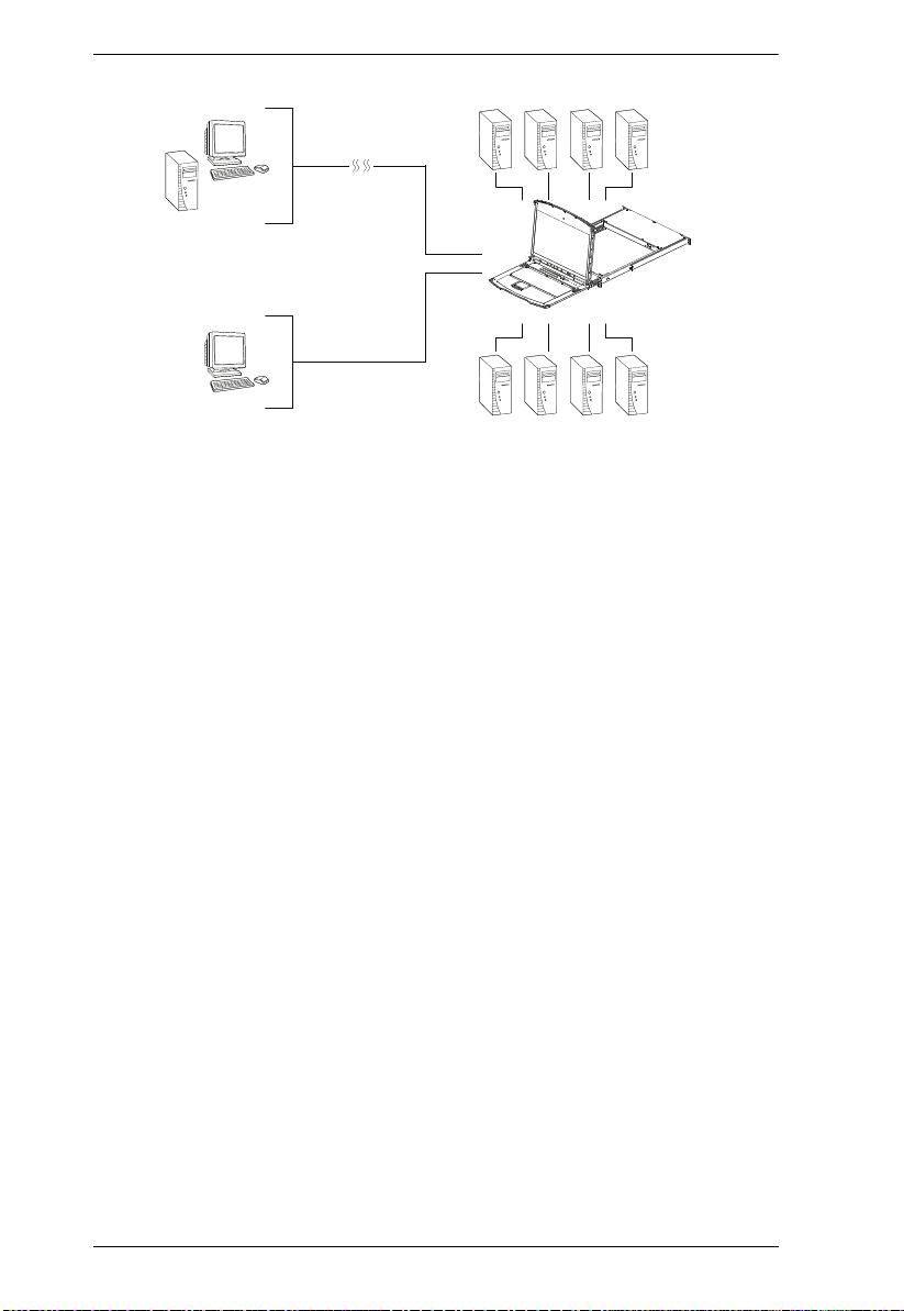
The KL1508Ai / KL1516Ai features IP-based connectivity that allows one
local operator and multiple remote operators to concurrently monitor and
access the computers on your installation. Because it uses TCP/IP for its
communications protocol, the KL1508Ai / KL1516Ai can be accessed from
any computer on the LAN, WAN, or Internet – whether that computer is
located down the hall, down the street, or halfway around the world.
1
KL1508Ai / KL1516Ai User Manual
Intern et
R emote Us er
KL1508A i/KL1516Ai
Extern al Local
Console
By daisy chaining up to 15 additional switches, as many as 256 computers can
be controlled from the original KVM console. An auto-sensing function
recognizes the position of each station on the chain, eliminating the need to
manually set the position, and a two digit seven-segment LED display on the
keyboard module showing each station's position for easy identification.
Compact, high-density, RJ-45 connectors and CAT 5e/6 cable make for a
compact, efficient, wiring configuration, while the use of PS/2 and USB KVM
Adapter Cables to link to the computers, permits any combination of Windows,
Macs, Sun computers, and serial devices to coexist on the installation.
For added convenience, ports for an external keyboard, monitor, and mouse ar e
provided on the rear panel – permitting you to manage the switch from an
external local console. There is also an external USB mouse port on the
keyboard module, allowing you to use an external mouse, rather than the
touchpad.
Access to any computer connected to the installation from the local console is
easily accomplished by means of a powerful mouse driven graphical OSD (On
Screen Display) menu system. A convenient Auto Scan feature also permits
automatic scanning and monitoring of the activities of all computers running
on the installation one by one.
Remo te opera tors con nect to th e KL150 8Ai / KL15 16Ai via its IP address from
anywhere on the LAN, WAN, or Internet via their browsers. Once they
successfully log in, they can take control using either the Windows Client or
Java Client utility. Inclusion of a Java-based client ensures that the KL1508Ai
/ KL1516Ai is platform independent, and is able to work with most operating
systems.
2

Chapter 1. Introduction
System administrators can handle a multitude of maintenance tasks smoothly
and efficiently – from installing and running GUI applications, to BIOS level
troubleshooting, routine monitoring, concurrent maintenance, system
administration, rebooting and even pre-booting functions – all from a remote
connection.
Remote operators can exchange keyboard, video and mouse signals with the
computers attached to the KL1508Ai / KL1516Ai just as if they were present
locally and working on the equipment directly.
Enhanced features include a Panel Array Mode that displays the video output
of up to 8 (KL1508Ai) or 16 (KL1516Ai) computers at the same time, and a
Message Board that allows logged in users to conveniently and instantly
communicate with one other – no matter where in the world they actually are.
The unit can be integrated into ATEN’s CC2000 Management Software.
CC2000 puts administrators in complete control of remote data centers and
branch offices no matter where they are in the world – allowing them to
remotely monitor and control all devices on a network. Refer to ATEN’s
website to get more information on CC2000.
Setup is fast and easy - plugging cables into their appropriate ports is all that is
entailed. Because the KL1508Ai / KL1516Ai intercepts keyboard input
directly, there is no need to get involved in complex installation routines or to
be concerned with incompatibility problems.
Since the KL1508Ai / KL1516Ai's firmware is upgradable over the Internet,
you can stay current with the latest functionality improvements simply by
downloading firmware updates from our website as they become available.
With its advanced security features, the KL1508Ai / KL1516Ai is the fastest,
most reliable, most cost effective way to remotely access and manage widely
distributed multiple computer installations.
3

KL1508Ai / KL1516Ai User Manual
Features
Hardware
Integrated KVM console with 17” or 19” LED-backlit LCD monitor in a
Dual Rail housing
Exclusive LED illumination light – designed by ATEN to illuminate the
keyboard and touchpad to allow visibility in low-light conditions
A single console controls up to 8 (KL1508Ai) or 16 (KL1516Ai)
computers
Daisy chain up to 15 additional KVM switches to control up to 256
computers*
One bus for remote KVM over IP access
Space-saving RJ-45 connectors and Cat 5e/6 cabling
KVM adapter cables designed with auto conversion to allow interface
combinations (PS/2, USB, Sun and serial) to control all computer types
Superior Video Quality – supports input video resolutions up to 1920 x
1200 @ 60 Hz** up to 30 meters, 1600 x 1200 @ 60 Hz up to 40 meters,
and 1280 x 1024 @ 75 Hz up to 50 meters
Extra console ports – manage computers on the LCD KVM switch from an
external console (monitor, USB or PS/2 keyboard, and USB or PS/2
mouse)
Multiplatform support: PC, Mac, Sun and Serial
Supports external USB mouse
Dual Rail housing is slightly less than 1U with top and bottom clearance
for smooth operation in 1U of rack space
Dual Rail – LCD monitor slides independently of the keyboard/touchpad
LCD module rotates up to 120 degrees for a comfortable viewing angle
Console lock – enables the console drawer to remain securely locked away
in position when not in use
LCD power button helps save energy and prolong displays’ life
Optional rack mount kits available, including easy installation options
Note: Compatible KVM switches: KH1508A/KH1516A, KH0116,
ACS1208A/ACS1216A, CS1708A/CS1716A, and KH1508/
KH1516.
4

Chapter 1. Introduction
With KVM Adapter Cable KA71xx or KA75xx series; please
check the product label to ensure it's the FHD version.
Management
Supports 64 user accounts and up to 32 users can be logged in at the same
time for control and management
End session feature – administrators can terminate any running session
Adapter ID – stores port information allowing administrators to relocate
servers to different ports, without having to reconfigure the adapters and
switch
Port Share Mode allows multiple users to gain access to a server
simultaneously
Remote power control for attached Power Over the NET™ devices
Supports integration into ATEN CC2000 Centralized Management
Software
Event logging and Windows-based Log Server support
Local Log Event
Firmware upgradeable
IPv6 capable
Easy-to-Use Interface
Easy computer selection via pushbuttons, Hotkey Mode, OSD (On-Screen
Display), and Browser-based GUI
Local Console, Browser, and AP GUIs offer a unified multi language
interface to minimize user training time and increase productivity
Multiplatform client support (Windows, Mac OS X, Linux, Sun)
Multi-browser support: Internet Explorer, Chrome, Firefox, Safari, Opera,
Mozilla, Netscape
Browser-based UI in pure Web technology allows administrators to
perform administrative tasks without the need for Java to be pre-installed
Panel Array Mode™
Keyboard broadcast* – keyboard input can be duplicated on all the
attached servers
5

KL1508Ai / KL1516Ai User Manual
Keyboard Language support: English (US); English (UK); German;
German (Swiss); French; Spanish; Traditional Chinese; Japanese; Korean;
Swedish; Italian; Russian; Hungarian and Greek
Note: Local Console only
Advanced Security
Remote authentication support: RADIUS, LDAP, LDAPS, and MS Active
Directory
Supports TLS 1.2 data encryption and RSA 2048-bit certificates to secure
user log ins from a browser
Flexible encryption design allows users to choose any combination of
DES, 3DES, AES, RC4, or Random for independent keyboard/mouse and
video data encryption
IP/MAC Filter support for enhanced security protection
Configurable user and group permissions for server access and control
Virtual Remote Desktop
Video quality and video tolerance can be adjusted to optimize data transfer
speed; monochrome color depth setting, threshold and noise settings for
compression of the data bandwidth in low bandwidth situations
Full-screen or sizable and scalable Virtual Remote Desktop
Message board feature allows logged in users to communicate with each
other
Mouse DynaSync™ – automatically synchronizes the local and remote
mouse movements
On-screen keyboard with multi language support
BIOS-level access
6

Chapter 1. Introduction
Requirements
General
We recommend computers with at least a P 4 2GHz processor, and 1 GB
RAM.
Browsers must support TLS 1.2 encryption.
A network transfer speed of at least 512kbps is recommended.
For the Log Server, you must have the Microsoft Jet OLEDB 4.0 or higher
driver installed.
External Console
A VGA, SVGA, or Multisync monitor capable of the highest resolution
that you will be using on any computer in the installation.
A USB or PS/2 style mouse
A USB or PS/2 style keyboard
Computers
The following equipment must be installed on the computers that connect to the
KL1508Ai or KL1516Ai's KVM ports:
A VGA, SVGA or Multisync port
A Type A USB port and USB host controller (for USB KVM Adapter
Cable Connection, see below)
6-pin mini-DIN keyboard and mouse ports (for PS/2 KVM Adapter Cable
Connection, see below)
Note: The integrated LCD monitor’s maximum screen resolution is 1280
x 1024 @ 75 Hz. If you want to use a higher setting for the screen
resolutions of the attached computers, see Screen Resolutions
Higher than 1280 x 1024, page 219.
KVM Adapter Cables
Cat 5e/6 cable is required to connect the KL1508Ai / KL1516Ai to one of the
KVM adapter cables.
7

KL1508Ai / KL1516Ai User Manual
The following KVM adapter cables are required for use with the KL1508Ai /
KL1516Ai:
Function Module
Connect to devices with PS/2 ports KA7920 / KA7520 / KA7120
Connect to devices with USB ports KA7970 / KA7570 / KA7166 /
Connect to Sun Legacy systems (with 13W3 port) KA9130 / KA7130
Connect to Sun USB systems KA9170 / KA7170
Connect to serial based devices KA9140
KA9520 / KA9120
KA7168 / KA7169 / KA7170
KA9570 / KA9170
Note: 1. KVM adapter cables are referred to as I/O Modules in some dialog boxes.
2. The following cable models support the Adapter Cable ID function:
KA7920 / KA7970 / KA7520 / KA7570 / KA7120 / KA7130 / KA7166
/ KA7168 / KA7169 / KA7170.
Adapter Cable Resolutions
The table below provides the maximum resolutions available for each KVM
adapter cable.
Model No. Computer Ports Video Resolution
KA7120 2 x PS/2, 1 x HDB-15 1920 x 1200
KA7130 1 x Min Din 8 Male
KA71xx
KA75xx KA7520 2 x PS/2, 1 x HDB-15
KA79xx KA7920 2 x PS/2, 1 x HDB-15 1600 x 1200
KA91xx KA9140 N/A 1024 x 768
8
KA7166 2 x USB Type A, 1 x DVI-D
KA7168 2 x USB Type A, 1 x HDMI
KA7169 2 x USB Type A, 1 x DisplayPort
KA7170 1 x USB Type A, 1 x HDB-15
KA7570 1 x USB, 1 x HDB-15
KA7970 1 x USB, 1 x HDB-15

Chapter 1. Introduction
Operating Systems
Supported operating systems are shown in the table below:
OS Version
Windows
2
Linux
UNIX IBM AIX4.3, 5L (V5.2,V5.3), V6 (V6.1)
Novell Netware 5.0 or later
Sun Solaris 8, 9, 10
Mac 9.0, 9.1, 10.1, 10.2, 10.3, 10.4 , 10.5
DOS
1
Does not support USB. 2 Kernels below 2.6 do not support USB 2.0
RedHat 9.0, Fedora or later, RHEL AS 4, RHEL 5
SuSE 10 or later, OpenSUSE 10.2; SLES 10 SP1
Debian 3.1, 4.0
Ubuntu 7.04, 7.10
FreeBSD 5.5, 6.1, 6.2
1
NT
, Server 2003, Server 2008, 2000 or later
6.2 or later
1
9
KL1508Ai / KL1516Ai User Manual
Components
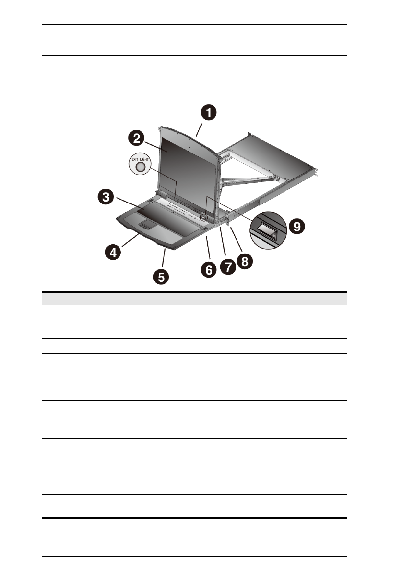
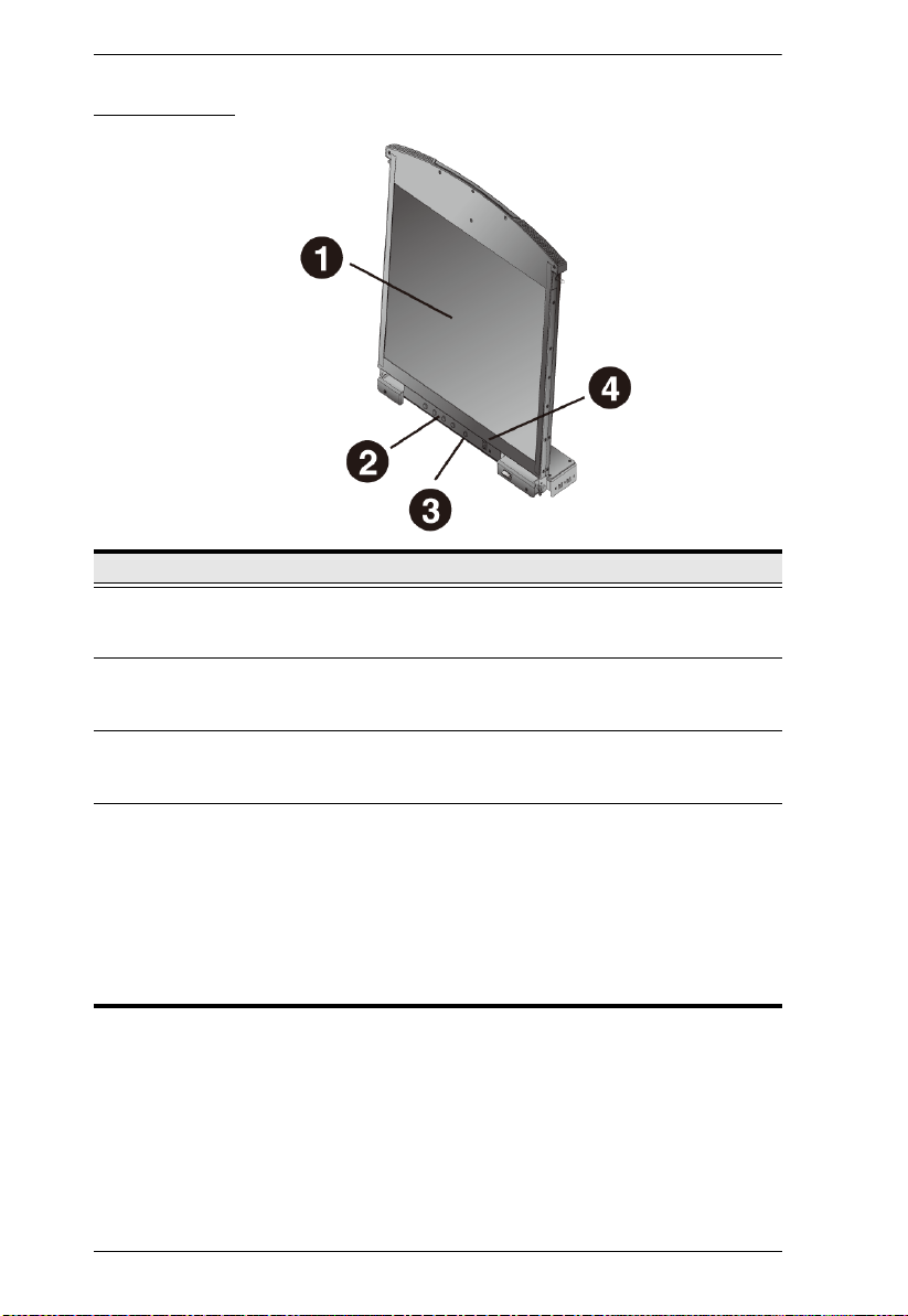
Front View
No. Component Description
1 Upper Handle Pull to slide the LCD module out; push to slide the module in.
2 LCD Module See LCD Module, page 12.
3 Keyboard Module See Keyboard Module, page 11.
4 Lower Handle Pull to slide the keyboard module out. See Opening the
5 Power LED Lights (blue) to indicate that the unit is receiving power.
6 Keyboard
Release Catch
7 LCD Release
Catch
8 Rack Mounting
Brackets
9 LED Illumination
Light
See Opening the Console, page 27, for details on sliding the
console in and out.
Console, page 27, for more details on sliding the console in
and out.
These catches (one on each side) release the keyboard
module so you can slide it away.
These catches (one on each side) release the LCD module
so you can slide it away.
The rack mounting brackets located at each corner of the
unit secure the chassis to a system rack. See Standard Rack
Mounting, page 16, for details.
Illuminates the keyboard and touchpad to allow visibility in
low-light conditions.
10
Chapter 1. Introduction
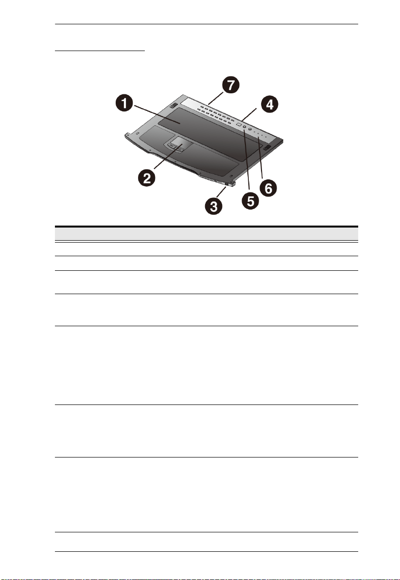
Keyboard Module
No. Component Description
1 Keyboard Standard 105-key keyboard
2 Touchpad Standard mouse touchpad
3 External Mouse
Port
4 Station ID LED In a daisy chained installation, the Station ID of the currently
5 Station Selection
Area
6 Lock LEDs &
Reset Switch
7 Port Selection
Buttons and
LEDs
This USB-type mouse port is provided for users who prefer to
use an external mouse.
selected station displays as a 2-digit figure in this
panel.See Port ID Numbering, page 37 for further details.
The LED displays the station number that the port with the
KVM focus is located on.
The left button shifts the KVM focus down the chain
(Station 2
to the last Station.
The right button shifts the KVM focus up the chain. After the
last Station, it cycles to Station 1.
The Num Lock, Caps Lock, Scroll Lock LEDs are located
here.
A Reset Switch is located just to the right of the Lock LEDs.
Press this recessed switch in with a thin object to perform a
system reset.
To access a Port on the currently selected Station press its
corresponding port selection button. Indicator LEDs are built
into the switches:
An On Line LED lights to indicate that the computer
attached to its corresponding port is up and running.
A Selected LED lights to indicate which port has the KVM
focus.
→
Station 1, etc.). After Station 1, it cycles back
11
KL1508Ai / KL1516Ai User Manual
LCD Module
No. Component Description
1 LCD Display To access the LCD monitor, slide the LCD module out and flip
2 LCD Controls These buttons control the position and picture settings of the
3 LCD On/Off
Button
4 Firmware
Upgrade Section
up the cover. See Opening the Console, page 27, for details
on sliding the LCD module out.
LCD display. See LCD OSD Configuration, page 33, for
details.
Push this button to turn the LCD monitor on and off. The
button lights when the LCD monitor is off to indicate that only
the monitor is off – not the KVM switch itself.)
Firmware Upgrade Port: The Firmware Upgrade Cable that
transfers the firmware upgrade data from the administrator's
computer to the KL1508Ai / KL1516Ai
connector.
Firmware Upgrade Switch: During normal operation this
switch should be in the NORMAL position. If firmware upgrade
fails, this switch is used to recover the situation.
See Recovering from Failed Firmware Upgrade, page 170, for
details.
plugs into this RJ-11
12

Chapter 1. Introduction
5
2
3
4
6
8
7
1
Rear View
No. Component Description
1 Grounding
Terminal
2 Power Socket This is a standard 3-pin AC power socket. The power cord
3 Power Switch This is a standard rocker switch that powers the unit on and
4 LAN Port The cable that connects the to the LAN plugs in here. The
5 PON Port This connector is provided for a Power over the Net™ (PON)
6 Daisy Chain Port When Daisy Chaining Units (See Daisy Chaining, page 25),
7 Local Console
Port Section
8 KVM Port
Section
The grounding wire used to ground the switch attaches here.
from an AC source plugs in here.
off.
LEDs indicate data transmission speed: ORANGE: 100 Mbps
/ GREEN: 1000 Mbps.
unit to plug into. A PON device allows computers attached to
the KL1508Ai / KL1516Ai to be booted remotely over the net.
Contact your dealer for more details.
the daisy chain cable plugs in here.
If this is a Single Station installation, or if this is the First
Station of a daisy chained installation, the keyboard, monitor,
and the mouse that make up the Local Console plug in here.
The Cat 5e/6 cables that link to the KVM Adapter Cables
(which link to the computers) plug in here.
* The KL1516Ai is pictured above. The KL1508Ai rear panel is the same as
that of the KL1516Ai, except that it has 8 KVM ports instead of 16.
13

KL1508Ai / KL1516Ai User Manual
This Page Intentionally Left Blank
14

Hardware Setup
1. Important safety information regarding the placement of this
device is provided on page 195. Please review it before
proceeding.
2. Make sure that power to all the devices you will be connecting
up has been turned off. You must unplug the power cords of any
computers that have the Keyboard Power On function.
3. Packing material has been inserted to protect the KL1508Ai /
KL1516Ai during shipping. Slide the LCD module out (see
Opening the Console, page 27), until the packing material is
visible. Remove the packing material before installing the unit,
as shown in the diagram below.
Before You Begin
Chapter 2
15

KL1508Ai / KL1516Ai User Manual
Left & Right L-shaped Brackets
Side Mounting Bracket
Standard Rack Mounting
A standard rack mounting kit is provided with your KL1508Ai / KL1516Ai.
The kit enables the switch to be mounted in a rack with a depth of 42–77 cm.
Note: It takes two people to mount the console.
The standard rack mounting kit does not include screws or cage
nuts. If you need additional screws or cage nuts, contact your rack
dealer.
16

Chapter 2. Hardware Setup
To rack mount the switch, do the following:
1. Have one person position the unit in the rack and hold it steady. Have the
second person screw the front brackets to the rack.
2. While the first person still holds the unit in place, the second person slides
the left & right L-shaped brackets into the unit’s side mounting brackets
from the rear, installing four screws in the brackets to secure them in place.
3. After the L-shaped brackets are secured, tighten all the screws.
Allow at least 5.1 cm on each side for proper ventilation, and at least 12.7
cm at the back for the power cord and cable clearance.
17

KL1508Ai / KL1516Ai User Manual
The CL5800 LCD KVM shown
here is used as a schematic
representation of this step.
Front-L Brackets Mounting
To have a comfortable and safe posture, install the Front-L Brackets which
provide an extension at the front of the rack to help the unit slide further out
and thus allowing you to tilt the LCD screen more. Instructions to use this
option are shown below:
1. Attach the left and right Front-L brackets to the front of the rack, placing
screws in the tabs to secure them in place.
Note: Rack screws are not provided to mount the unit. We recommend that
you use M5 x P0.8 screws.
2. Have one person position the unit in the rack and hold it steady. Have the
second person screw the front brackets to the front-L bracket.
18

Chapter 2. Hardware Setup
The CL5800 LCD KVM shown
here is used as a schematic representation
of this step.
3. While the first person still holds the unit in place, the second person slides
the left & right L-shaped brackets into the unit’s side mounting brackets
from the rear, installing four screws in the brackets to secure them in place.
4. After the L-shaped brackets are secured, tighten all the screws.
Allow at least 5.1 cm on each side for proper ventilation, and at least 12.7
cm at the back for the power cord and cable clearance.
19

KL1508Ai / KL1516Ai User Manual
Optional Rack Mount Kits
For convenience and flexibility, optional rack mount kits are available and are
listed in the table below:
Mounting Kit Description
Standard Long Rack Mount
Kit
Easy Installation Rack
Mount Kit
Note: For more information, visit the product webpage and refer to the
Compatible Accessories.
For detailed installation steps, visit the product webpage and refer
to the Optional Rack Mount Kits Installation Guide.
This kit is the long-railed version of your standard
mounting kit that lets you fit your device to racks with
greater depth.
This kit is designed to be easy to install and can be
installed by one person
20

Chapter 2. Hardware Setup
Single Stage Installation
In a Single Stage installation, there are no additional switches daisy chained
down from the first unit. To set up a single stage installation, refer to the
installation diagrams beginning on the following page (the numbers in the
diagram correspond to the numbers of the installation steps), and do the
following:
1. Ground the KL1508Ai / KL1516Ai by connecting one end of a grounding
wire to the grounding terminal, and the other end of the wire to a suitable
grounded object.
Note: Do not omit this step. Proper grounding helps to prevent damage to
the unit from surges or static electricity.
2. If you choose to install an external console, plug your keyboard, monitor,
and mouse into the Console Ports located on the switch’s rear panel. The
ports are color coded and marked with an icon to identify themselves.
Note: This step is optional.
3. For each of the computers you are installing, use Cat 5e cable to connect
any available KVM port to a KVM adapter cable that is appropriate for the
computer you are installing. (See KVM Adapter Cables, page 7, for
adapter cable details.)
Note: The maximum supported distance to the adapter cable is 50 m.
4. Connect the KVM Adapter cable to the computer. Refer to the KVM
Adapter Cable Installation Diagram, page 23, to plug the adapter cable
connectors into their respective ports on the computers you are installing.
5. Plug the LAN or WAN cable into the KL1508Ai / KL1516Ai’s LAN port.
6. Connect the power cord to the switch and to an AC power source.
After the KL1508Ai / KL1516Ai is cabled up, you can turn on the power. After
the switch is powered up, you can turn on the servers.
21

KL1508Ai / KL1516Ai User Manual
5
4
1
2
b
y A
TEN
P
S/
2
C
P
U
M
O
D
U
L
E
MODEL
NO. KA9120
P
S/
2
C
P
U
M
O
D
U
L
E
MODEL
NO. KA9120
LIN
K
3
2
3
6
Single Stage Installation Diagram
22

KVM Adapter Cable Installation Diagram
KA7120
KA7520
KA7920
KA9120
KA9520
b
y A
TEN
LIN
K
KA7170
KA7570
KA7970
KA9170
KA9570
b
y A
TEN
LIN
K
KA9140
SERIAL TERMINAL
KA7130
KA9130
b
y A
TEN
LIN
K
Chapter 2. Hardware Setup
23

KL1508Ai / KL1516Ai User Manual
8
9
KVM Adapter Cable Installation Diagram cont.
KA7166
KA716
24
KA716

Chapter 2. Hardware Setup
Daisy Chaining
To control even more computers, up to 15 additional compatible KVM
switches can be daisy chained from the original KL1508Ai or KL1516Ai. As
many as 256 computers can be controlled from a single console in a complete
installation.
Note: Refer to the table Supported Devices, page 224 for a list of ATEN
switches that can be installed on a KL1508Ai / KL1516Ai daisy chain.
Tables showing the relation between the number of computers and the number
of compatible KVM switch units needed to control them are provided on
page 223.
To set up a daisy chained installation, make sure that power to all the devices
you will be connecting up has been turned off, and refer to the Daisy Chain
Installation Diagram, page 26 as you do the following:
1. Use a daisy chain cable set to connect the Chain Out port of the first
station (the KL1508Ai / KL1516Ai unit) to the Chain In port of the
chained compatible KVM Switch unit (first station out to second station
in, second station out to third station in, etc.).
Note: 1. You cannot use the chain in port of the First Station.
2. Daisy chain cable sets require a separate purchase. See your
dealer for details.
2. Cable up the computers and the switch according to the information
provided under Single Stage Installation, page 21.
3. Repeat the above for any other switches you want to add to the chain.
4. Power up the installation according to the following procedure:
a) Plug in the power cord for the first station. Wait for the unit to ascertain
its station ID and display it on the Station ID LED. (The station ID for
the first stage unit is 01, the ID for the second stage unit is 02, the ID for
the third stage unit is 03, etc.)
b) Power on each station on the installation in turn (second station, then
third station, etc.). In each case, wait for the station ID to be ascertained
and displayed before powering on the next station.
c) After all the stations are up, power on the computers.
25

KL1508Ai / KL1516Ai User Manual
Daisy Chain Installation Diagram
KL1508Ai Rear
KH1508A Rear
KH1508A Rear
26

Chapter 3
Release Catch
Basic Operation
Opening the Console
The KL1508Ai / KL1516Ai’s console consists of two modules: an LCD
display module located under the top cover; and a keyboard/touchpad module
below the LCD module.
The modules can either slide together, or independently. This allows you to
have the LCD display available for viewing while the keyboard/touchpad
module is conveniently out of the way when not in use.
Opening Separately
1. Pull the release catch to release the console, and pull the top panel a few
centimeters toward you. Once the console has been released, you can let
go of the catch.
27

KL1508Ai / KL1516Ai User Manual
2. Pull the top panel all the way out until it clicks into place.
3. Rotate the top panel all the way back to expose the LCD screen.
28

Chapter 3. Basic Operation
4. Reach underneath and pull the keyboard module all the way out until it
clicks into place.
Opening Together
Refer to the diagrams in the Opening Separately section as you do the
following:
1. Pull the release catch and pull the top and bottom panels out until the
keyboard module clicks into place.
Note: Once the console has been released, you can let go of the catch.
2. Pull the top panel the rest of the way out until it clicks into place.
3. Rotate the top panel all the way back to expose the LCD screen.
Note: Refer to the warning regarding placing excessive weight on the
keyboard module on the following page.
29

KL1508Ai / KL1516Ai User Manual
The maximum load bearing capacity of the keyboard module is
30kg. Failure to heed the information below can result in damage
to the keyboard module.
Operating Precautions
RIGHT
Rest your hands and arms lightly on the
keyboard module as you work.
WRONG!
DO NOT lean your body weight on the
keyboard module.
DO NOT place heavy objects on the
keyboard module.
30

Chapter 3. Basic Operation
Closing the Console
1. Pull the release catches located on either side of the keyboard toward you
to release the keyboard module, then slide the module slightly in.
2. Let go of the catches. Using the front handle, push the keyboard module
all the way in.
31

KL1508Ai / KL1516Ai User Manual
3. Rotate the LCD module all the way down, then pull the rear catches to
release the LCD module.
4. Using the front handle, push the module all the way in.
32

Chapter 3. Basic Operation
LCD OSD Configuration
The LCD Buttons
The LCD OSD allows you to set up and configure the LCD display. Four
buttons (see LCD Controls, page 12), are used to perform the configuration, as
described in the table below:
Button Function
MENU When you have not entered the LCD OSD Menu
EXIT
function, pressing this button invokes the Menu
function and brings up the Main Menu.
When navigating through the menus, this button
moves you right or up. When making an adjustment, it
increases the value.
When navigating through the menus, this button
moves you left or down. When making an adjustment,
it decreases the value.
When you have not entered the LCD OSD Menu
function, pressing this button performs an auto
adjustment. An auto adjustment automatically
configures all the settings for the LCD panel to what
the OSD considers their optimum values to be.
When you have entered the LCD OSD Menu
function, pressing this button exits the current menu
and returns you to the previous menu. Use it to
leave an adjustment menu when you are satisfied
with the adjustment you have made.
When you are at the Main Menu, pressing this
button exits the LCD OSD.
33

KL1508Ai / KL1516Ai User Manual
The Adjustment Settings
An explanation of the LCD OSD adjustment settings is given in the table
below:
Setting Explanation
Brightness Adjusts the background black level of the screen image.
Contrast Adjusts the foreground white level of the screen image.
Phase If pixel jitter or horizontal line noise is visible on the display, your
Clock If vertical banding is visible on the display, your LCD may have
H-Position Positions the display area on the LCD panel horizontally (moves
V-Position Positions the display area on the LCD panel vertically (moves
Color Temperature Adjusts the color quality of the display. You can adjust the
Language Selects the language that the OSD displays its menus in.
OSD Duration Lets you set the amount of time that the OSD displays on the
Reset Resets the menu and submenu adjustments (except for
LCD may have the wrong phase setting. Adjust the phase setting
to eliminate these problems.
the wrong clock setting. Adjust the clock setting to eliminate
vertical banding.
the display area left or right).
the display area up or down).
“warmth” value, color balance, etc. The Adjust Color selection
has a further submenu that lets you fine tune the RGB values.
screen. If there is no input for the amount of time you choose, the
OSD display turns off.
language settings) to the original factory default settings.
34

Chapter 3. Basic Operation
Port Selection
KL1508Ai / KL1516Ai installations provide three methods to obtain instant
access to any computer in your installation: Manual, OSD/GUI, and Hotkey.
Manual
For manual port selection, simply press the Port Switch that corresponds to the
device you wish to access.
OSD / GUI
The KL1508Ai / KL1516Ai provides menu driven interfaces to the computer
switching procedure. There are two systems: A text-based OSD when you log
in from the local console; and a graphical user interface (GUI) when you log in
remotely over the internet. Local console OSD operation is discussed in the
next chapter; GUI operation is discussed from Chapter 5 onwards for Internet
browser, and Windows and Java logins.
Hotkeys
Hotkeys allow you to conveniently provide KVM focus to a particular
computer from the local console keyboard, instead of having to manually select
them by pressing Port Selection switches. See Hotkey Port Control, page 55,
for details.
35

KL1508Ai / KL1516Ai User Manual
Hot Plugging
The KL1508Ai / KL1516Ai supports hot plugging – components can be
removed and added back into the installation by unplugging and replugging
their cables from their ports without the need to shut the unit down. In order for
hot plugging to work properly, however, the procedures described below must
be followed.
Hot Plugging Stations
You can switch station positions by simply unplugging from the old parent and
plugging into a new one. After you do, in order for the OSD menus to
correspond to the change, you must reset the OSD. See RESET STATION IDS,
page 48, for details.
Hot Plugging KVM Ports
After switching KVM ports, in order for the OSD menus to correspond to the
change, you must manually reconfigure the OSD information for the new Port
information. See F3: SET, page 44, and the Port Setting selections under the
F4 ADM function, page 47, for details.
Note: If the computer’s Operating System doesn’t support hot plugging, this
function may not work properly.
Hot Plugging Console Ports
Keyboard, monitor, and mouse can all be hot plugged. When hot plugging
the mouse:
You may unplug the mouse and plug it back in again (to reset the mouse,
for example), as long as you use the same mouse.
If you plug in a different mouse, all the stations and all the computers on
the installation must be shut down for 10 seconds, then restarted following
the Power Up Sequence described under Step 6 on page 25.
Some older operating systems may not support hot-plugging.
Note: If, after hot plugging (or at any other time), there is no response to
keyboard and/or mouse input, perform a Keyboard and Mouse Reset
by pressing in the Reset switch (see page 61).
36

Chapter 3. Basic Operation
Powering Off and Restarting
If it becomes necessary to power off the KL1508Ai / KL1516Ai, or if the
switch loses power and needs to be restarted, before starting it back up you
must follow these procedures:
1. Shut down all the computers that are attached to it.
Note: You must unplug the power cords of any computers that have the
Keyboard Power On function.
2. Wait 10 seconds then power it back on. If you have shut down more than
one station, power up the highest station first and work your way down to
the lowest one. Wait for each station to display its Station ID on the front
panel LED before powering on the next one.
3. After the station(s) is (are) up, power the computers back on.
Port ID Numbering
Each computer on the installation is assigned a unique Port ID. The Port ID is
a one or two segment number that is determined by the Stage Level and KVM
Port number of the KVM switch that the computer is connected to.
The first segment represents the KVM Port number of the First Stage unit; the
second segment represents the KVM Port number of the Second Stage unit.
A computer attached to a First Stage unit has a one segment Port ID (from 1–
16) that corresponds to the KVM Port number that it is connected to.
A computer attached to a Second Stage unit has a two segment Port ID:
The second segment (from 1–16), represents the KVM Port number on the
Second Stage unit that the computer is connected to. The first segment
(from 1–16) represents the KVM Port number on the First Stage unit that
the Second Stage unit links back to.
For example, a Port ID of 12–3 refers to a computer that is connected to
KVM Port 3 of a Second Stage unit that links back to KVM Port 12 of the
First Stage unit.
37

KL1508Ai / KL1516Ai User Manual
This Page Intentionally Left Blank
38

Chapter 4
OSD Operation
OSD Overview
The On Screen Display (OSD) is a menu driven method to handle computer
control and switching operations. All procedures start from the OSD Main
Screen. To display the Main Screen, tap the OSD hotkey twice.
The default hotkey is [Scroll Lock]. You can change the hotkey to the Ctrl key
or the Alt key if you like (see OSD HOTKEY, page 44).
Note: 1. If you use the Ctrl or Alt key method you must press the same Ctrl or
Alt key both times.
2. Once you start the OSD, the keyboard lock will be controlled by the
device. When the OSD is being accessed, the number lock and caps
lock will always be on and usernames/passwords are not casesensitive.
The OSD incorporates a two level (administrator / user) password system.
Before the OSD Main Screen comes up, a login dialog box appears that asks
for a username and password. You must provide a valid username and
password in order to continue.
The first time that the OSD is accessed, you must use the default username and
password. The default username is administrator and the default password is
password. For security purposes, it is STRONGLY recommended that you
change the password.
After logging in with the default username and password, the OSD Main
Screen opens in Administrator mode. In this mode, you have administrator
privileges, with access to all administrator and user functions, and can set up
operations (including password authorization for the future), as you would like.
39

KL1508Ai / KL1516Ai User Manual
When you invoke the OSD, a screen similar to the one below appears:
Note: The diagram depicts the Administrator's Main Screen. The User Main
Screen does not show the F4 and F6 functions, since these are reserved
for the administrator and can't be accessed by ordinary users.
Manufacturing Number
The “MFG Number” (Manufacturing Number) is an internal serial number
used by ATEN’s factory and technical support staff to identify products. This
number does not affect products’ warranty. If your product requires after-sales
services, you may provide the MFG Number to ATEN’s sales or technical
support staff to identify the product and model number.
40

Chapter 4. OSD Operation
OSD Navigation
To dismiss the menu, and deactivate the OSD, click the X at the upper
right corner of the OSD Window or press Esc.
To Logout click F8 or the
ZZ
symbol at the top of the Main Screen, or
Z
press [F8].
The OSD uses a tree view. To see the ports for a particular station, click
the plus sign [
+
] in front of the station number. The port number list
drops down. To dismiss the list, click the circle symbol [ o ] in front of the
station number.
To move up or down through the list one line at a time, click the up and
down triangle symbols (ST
)
or use the up and down arrow keys. If there
are more list entries than there is room for on the Main Screen, the screen
will scroll.
To move up or down through the list one screen at a time, click the up and
down arrow symbols (), or use the [Pg Up] and [Pg Dn] keys. If there
are more list entries than there is room for on the Main Screen, the screen
will scroll.
To bring the KVM focus to a port, double-click it, or move the highlight
bar to it and then press [Enter].
After executing any action, you automatically go back to the menu one
level above.
OSD Main Screen Headings
Heading Explanation
SN-PN This column lists the port ID numbers (station number-port number) for
all the KVM ports on the installation. The simplest method to access a
particular computer is to click it, or move the highlight bar to it, and then
press [Enter].
QV If a port has been selected for Quick View scanning an arrowhead
displays in this column.
The computers that are powered on and are online have a sun symbol
in this column.
NAME If a port has been given a name (see EDIT PORT NAMES, page 47), its
name appears in this column.
41

KL1508Ai / KL1516Ai User Manual
OSD Functions
OSD functions are used to configure and control the OSD. For example, you
can rapidly switch to any port, scan selected ports only, limit the list you wish
to view, designate a port as a Quick View Port, create or edit a port name, or
make OSD setting adjustments.
To access an OSD function:
1. Either click a function key field at the top of the Main Screen, or press a
function key on the keyboard.
2. In the submenus that appear make your choice either by double clicking it,
or moving the highlight bar to it, and then pressing [Enter].
3. Press [Esc] to return to the previous menu level.
F1: GOTO
Accessing the GOTO function allows you to switch directly to a port either by
keying in the port's name or its port ID.
To use the Name method, key in 1, key in the port's name, and then press
[Enter].
To use the Port ID method, key in 2, key in the port ID, and then press
[Enter].
Note: You can key in a partial name or port ID. The screen will show all the
computers that the user has View rights to that match the name or port
ID pattern, regardless of the current List settings (see F2: LIST, page 43,
for details).
To return to the OSD Main Menu without making a choice, press [Esc].
42

Chapter 4. OSD Operation
F2: LIST
Many of the switch’s OSD functions only operate on the computers currently
selected for listing on the Main Screen. Accessing this function lets you
broaden or narrow the scope of ports that get listed. The submenu choices and
their meanings are given in the table below:
Choice Meaning
ALL Lists all of the ports on the installation.
QUICK VIEW Lists only the ports that have been selected as Quick View Ports.
POWERED ON Lists only the ports that have attached computers Powered On.
QUICK VIEW +
POWERED ON
Move the highlight bar to the choice you want, then press [Enter]. An icon
appears before the choice to indicate that it is the currently selected one.
Lists only the ports that have been selected as Quick View Ports,
and that have their attached computers Powered On.
43

KL1508Ai / KL1516Ai User Manual
F3: SET
Accessing this function allows the administrator and each user to set up an
individual working environment. A separate profile for each operator is stored
by the OSD and is activated according to the username provided during login.
To change a setting:
1. Double-click it; or move the highlight bar to it, then press [Enter].
2. After you select an item, a submenu with further choices appears. To make
a selection, either double click it; or move the highlight bar to it, then press
[Enter]. An icon appears before the selected choice to indicate which one
it is. The settings are explained in the following table:
Setting Function
OSD
HOTKEY
PORT ID
DISPLAY
POSITION
PORT ID
DISPLAY
DURATION
PORT ID
DISPLAY
MODE
SCAN
DURATION
Selects which hotkey activates the OSD function:
[Scroll Lock] [Scroll Lock]; [Ctrl] [Ctrl] or [Alt] [Alt].
Since the [Ctrl] or [Alt] key combinations may conflict with programs
running on the computers, the default is the [Scroll Lock] combination.
Allows you to position where the port ID appears on the monitor. The
default is the upper left corner, but you can choose to have it appear
anywhere on the screen.
Use the mouse or the arrow Keys plus Pg Up, Pg Dn, Home, End, and
5 (on the numeric keypad with Num Lock off), to position the port ID
display, then click or press [Enter] to lock the position and return to the
Set submenu.
Note: The setting affects the currently selected port. If you don’t want
to use the default position, you must change the setting for each port
individually.
Determines how long a port ID displays on the monitor after a port
change has taken place. There are two choices: 3 seconds and Off.
Selects how the port ID is displayed: the port number alone (PORT
NUMBER); the port name alone (PORT NAME); or the port number
plus the port name (PORT NUMBER + PORT NAME). The default is
PORT NUMBER + PORT NAME).
Determines how long the focus dwells on each port as it cycles through
the selected ports in Auto Scan mode (see F7: SCAN, page 52). Key in
a value from 1–255 seconds, then press [Enter]. Default is 5 seconds;
a setting of 0 disables the Scan function.
44

Chapter 4. OSD Operation
Setting Function
SCAN/SKIP
MODE
SCREEN
BLANKER
HOTKEY
COMMAND
MODE
HOTKEY This setting selects the Hotkey invocation keys (see Hotkey Operation,
OSD
LANGUAGE
SET
CONSOLE
KEYBOARD
SET
LOGOUT
TIMEOUT
ACTIVATE
BEEPER
Selects which computers will be accessed under Skip mode (see F5:
SKP, page 50), and Auto Scan mode (see F7: SCAN, page 52).
Choices are:
–
All the ports which have been set Accessible;
ALL
POWERED ON
and are Powered On;
QUICK VIEW + POWERED ON
set Accessible and have been selected as Quick View Ports and are
Powered On. The default is ALL.
If there is no input from the console for the amount of time set with this
function, the screen is blanked. Key in a value from 1–30 minutes, then
press [Enter]. A setting of 0 disables this function. The default is Off.
Enables / Disables the Hotkey function (see OSD Operation, page 39),
in case a conflict with programs running on the computers occurs. The
default is On.
page 55). Choices are [NUM LOCK] + [-], or [CTRL] + [F12]. The
default is [NUM LOCK] + [-].
Sets the language that the OSD displays in. Choices are: English,
German, Japanese, Simplified Chinese, Traditional Chinese, Spanish,
Russian, and French. The default is English.
Sets the keyboard language mapping of the console keyboard. The
default is Auto. If the switch does not automatically receive language
mapping from the keyboard, it will set to English (US).
If there is no input from the console for the amount of time set with this
function, the operator is automatically logged out. A login is necessary
before the console can be used again.
This enables other operators to gain access to the computers when the
original operator is no longer accessing them, but has forgotten to log
out. To set the timeout value, key in a number from 1–180 minutes,
then press [Enter]. If the number is 0 (zero), this function is disabled.
Default is Off.
Choices are Y (for Yes), or N (for No). When activated, the beeper
sounds whenever a port is changed, when activating the Auto Scan
function (see F7: SCAN, page 52), or an invalid entry is made on an
OSD menu. The default is On.
–
Only those ports which have been set Accessible
–
Only those ports which have been
(Continues on next page.)
45

KL1508Ai / KL1516Ai User Manual
(Continued from previous page.)
Setting Function
PREFERRED
RESOLUTION
TOUCHPAD Enables / Disables the touchpad function of the console. Choices are
This function allows you to set the preferred resolution for a second
external display* connected to the switches console port, which will be
sent to the KVM adapter cables. The KVM adapter cables provide the
connected computer’s video card with EDID information about the
monitor connected to the switch. This affects the video quality
displaying on the external console monitor. Choices are:
MONITOR DEFAULT SETTING – Sends the EDID information
–
provided by the switches LCD monitor
Alternative Resolution – Sends the alternative resolution (EDID
information) selected for the external display connected to the
switches console port, to the KVM adapter cables. Select a
resolution that best suits the video display for the monitor connected
to the switches console port.
Note: When using the built in LCD monitor the default resolution must
be set to 1280x1024 60HZ. Only change the preferred resolution
when connecting an external display to the console monitor port.
Y (for Yes), or N (for No). The active status (Touchpad On / Touchpad
Off) is also shown.
to the KVM adapter cable.
46

Chapter 4. OSD Operation
F4: ADM
F4 is an administrator only function. Accessing this function allows the
administrator to configure and control the overall operation of the OSD. To
change a setting double click it; or use the up and down arrow keys to move the
highlight bar to it, then press [Enter].
After you select an item, a submenu with further choices appears. Double click
the choice you want, or move the highlight bar to it, then press [Enter]. An icon
appears before the selected choice. The settings are explained in the table on
the next three pages:
Setting Function
SET IP
ADDRESS
EDIT PORT
NAMES
RESTORE
DEFAULT
VAL UES
CLEAR THE
NAME LIST
This function is used to select whether to assign the KL1508Ai/
KL1516Ai’s IP address automatically (DHCP), or to give it a fixed IP
address.
Enable DHCP to assign the IP address automatically.
Disable DHCP to assign a fixed IP address and specify the IP, Mask,
and Gateway in the appropriate fields.
Note: The default setting for DHCP is disabled.
To identify which computer is attached to a particular port, every port
can be assigned a name. This function allows the administrator to
create, modify, or delete port names. To assign a port name:
1. Click the port you want, or use the navigation keys to move the
highlight bar to it, then press [Enter].
2. Key in the new port name, or modify/delete the old one. The maximum number of characters allowed for the port name is 14. Legal
characters include:
All alpha characters: A–Z*
All numeric characters: 0–9
*You can enter the port names in either upper or lower case
however the OSD displays the port name only in UPPERCASE.
3. When you have finished editing, press [Enter] to have the change
take effect. To abort the change, press [Esc].
This function is used to undo all changes and return the setup to the
original factory default settings (see OSD Factory Default Settings,
–
page 227)
ports, which are saved.
This function clears the port name list.
except for the Names settings that were assigned to the
(Continues on next page.)
47

KL1508Ai / KL1516Ai User Manual
(Continued from previous page.)
Setting Function
RESET
STATION IDS
SET
OPERATING
SYSTEM
SET CAT 5
LENGTH
SET
KEYBOARD
LANGUAGE
FIRMWARE
UPGRADE
ADAPTER
UPGRADE
SET
CONSOLE
MODE
If you change the position of one of the stations in the daisy chain, the
OSD settings will no longer correspond to the new situation. This
function directs the OSD to rescan the station positions of the entire
installation and updates the OSD so that the OSD station information
corresponds to the new physical layout.
Note: Only the station numbers get updated. Except for the port
names, all administrator settings, for all of the computers affected by
the change, have to be manually redone.
Specifies the operating platform of the computer attached to each port.
You must configure each port on the installation. For each port, press
the [Spacebar] to cycle through the choices (PC, Mac or Sun). Repeat
until all the ports have been set, then press [Esc]. The default is PC.
Note: If you are installing a Sun or Mac computer it may not boot when
you run it for the first time unless you first set the correct operating
system for the port it is connected to.
Lets you specify how long the Cat 5e/6 cable between the port and the
KVM adapter cable is. Press [Spacebar] to cycle through the cable
length settings:
S: Short – for up to 25 m
M: Medium – for between 20 and 35 m
L: Long – for above 35 m
An S, M, or L appears next to the port to indicate the choice.
Sets the keyboard language layout for the computers attached to each
port. Press [Spacebar] to cycle through the choices: The default is
English (US).
In order to upgrade the KL1508Ai/KL1516Ai and adapter cable
firmware you must first enable Firmware Upgrade mode with this
setting.
When you bring up this menu, the current firmware version of the KVM
switch and the iCard will be displayed. Select Y to enable Firmware
Upgrade mode, or N to leave this menu without enabling it.
This function allows the administrator to check the firmware version of
the KVM adapter cable. When you bring up this menu, the current
firmware version levels display. See FIRMWARE UPGRADE, above,
also.
This setting selects which console(s) (internal/external) are enabled:
0 Both Consoles enabled
1 LCD Console only
2 External console only
Use the spacebar to cycle through the choices. The default is 0.
Changes will not be saved until you logout.
48

Chapter 4. OSD Operation
SET VIDEO
HV MODE
This setting selects the video mode (separate or composite video sync
signals) the port(s) (internal/external) is using. Press [Spacebar] to
enter this setting and see a list of ports.
Use the [Spacebar] to cycle through the choices. The choices are:
S Separate (default)
C Composite
Changes will not be saved until you exit to the main menu.
Note: If your dongle does not support video HV mode, the unit will emit
a beeping sound whenever you cycle through the choices. The
supported dongles are KA7170, KA7570, KA7166, KA7168 and
KA7169.
49

KL1508Ai / KL1516Ai User Manual
F5: SKP
This function enables you to easily skip backward or forward, switching the
console focus from the currently active KVM Port to the previous or next
available one.
The selection of computers to be available for Skip mode switching is
made with the Scan/Skip mode setting under the F3 SET function
(see page 45).
When you are in Skip mode, press:
← To skip to the previous port in the List.
→ To skip to the next port in the List.
↑ To skip to the last port of the previous station in the List.
↓ To skip to the first port of the next station in the List.
Note: When you skip, you only skip to the previous or next available
computer that is in the Scan/Skip mode selection (see page 45).
If a port has been selected for Scan/Skip mode, when the focus switches to
that port a left/right triangle symbol appears before its port ID display.
While Skip mode is in effect, the console will not function normally. You
must exit Skip mode in order to regain control of the console.
To exit Skip mode, press the [Spacebar] or [Esc].
50

Chapter 4. OSD Operation
F6: BRC
F6 is an administrator only function. When this function is in effect, commands
sent from the console are broadcast to all available computers on the
installation.
This function is particularly useful for operations that need to be performed on
multiple computers, such as performing a system wide shutdown, installing or
upgrading software, etc.
While BRC mode is in effect, a speaker symbol appears before the port ID
display of the port that currently has the console focus.
While BRC mode is in effect, the mouse will not function normally. You
must exit BRC mode in order to regain control of the mouse.
To exit BRC mode, invoke the OSD (with the OSD Hotkey), then click the
F6 field, or press [F6], to turn BRC mode off.
51

KL1508Ai / KL1516Ai User Manual
S
F7: SCAN
This function automatically switches among the available computers at regular
intervals so that you can monitor their activity without having to take the
trouble of switching manually.
The selection of computers to be included for Auto Scanning is made with
the Scan/Skip mode setting under the F3 SET function (see page 45).
The amount of time that each port displays for is set with the Scan
Duration setting under the F3 SET function (see page 44).
As each computer is accessed, an appears in front of the port ID
display to indicate that it is being accessed under Auto Scan mode.
While you are in Auto Scan mode, you can pause the scanning in order to
keep the focus on a particular computer either by pressing P, or with a left
click of the mouse. To resume scanning, press any key or left click again.
See Auto Scan Mode Switching, page 58, for details.
While Auto Scan mode is in effect, the console will not function normally.
You must exit Auto Scan mode in order to regain control of the console.
To exit Auto Scan mode, press the [Spacebar] or [Esc].
52

Chapter 4. OSD Operation
F8: LOUT
Clicking the F8 field, or pressing [F8], logs you out of the OSD and blanks the
console screen. This is different from simply deactivating the OSD when you
are at the Main Screen by pressing [Esc].
With this function you must log in all over again to regain access to the OSD,
whereas with [Esc], all you have to do to reenter the OSD is tap the OSD
Hotkey.
Note: 1. When you reenter the OSD after logging out, the screen stays blank
except for the login dialog box. You must input your username and
password before you can continue (see page 39).
2. If you reenter the OSD after logging out, and immediately use [Esc]
to deactivate the OSD without having selected a port from the OSD
menu, a Null Port message displays on the screen. The OSD hotkey
will bring up the OSD Main Screen.
53

KL1508Ai / KL1516Ai User Manual
This Page Intentionally Left Blank
54

Chapter 5
Hotkey Operation
Hotkey Port Control
Hotkey port control allows you to provide KVM focus to a particular computer
directly from the keyboard. The KL1508Ai / KL1516Ai provides the following
Hotkey port control features:
Selecting the Active Port
Auto Scan Mode Switching
Skip Mode Switching
Computer Keyboard / Mouse Reset
The following settings can also be controlled in Hotkey mode:
Setting the Beeper
Setting the Quick Hotkey
Setting the OSD Hotkey
Setting the Port Operating System
Restoring the OSD Default Values
55

KL1508Ai / KL1516Ai User Manual
Invoking Hotkey Mode
All Hotkey operations begin by invoking Hotkey mode.1 To invoke Hotkey
mode you may use two possible keystroke sequences shown below. Only one
of the two key-sequences below can be operational (see Setting the Hotkey key
combination on page 62):
Number Lock and Minus Keys
1. Hold down the
2. Press and release the
3. Release the
[Num Lock] + [-]
[Num Lock]
[Minus]
[Num Lock]
key;
key;
key:
Control and F12 Keys
1. Hold down the
2. Press and release the
3. Release the
[Ctrl] + [F12]
[Ctrl]
[Ctrl]
[F12]
key:
key;
key;
Hotkey Mode Environment
When Hotkey mode is active:
A command line appears on the monitor screen. The command line prompt
is the word Hotkey: in white text on a blue background, and displays the
subsequent Hotkey information that you key in.
Ordinary keyboard and mouse functions are suspended – only Hotkey
compliant keystrokes (described in the sections that follow), can be input.
Exiting Hotkey Mode
Pressing
[
Esc] exits Hotkey mode.
1. Make sure that the Hotkey Command Mode function is enabled and
that you key in the appropriate Hotkey. See page 45 for details.
56

Chapter 5. Hotkey Operation
Selecting the Active Port
Each computer port is assigned a port ID (see Port ID Numbering, page 37).
You can directly access any computer with a Hotkey combination that specifies
the port ID that the computer is connected to. The steps are:
1. Enter the Hotkey mode with the:
[Num Lock] + [-] or [Ctrl] + [F12]
2. Key in the port ID.
The port ID numbers display on the command line as you key them in. If
you make a mistake, use
[Backspace]
combination.
to erase it.
3. Press
[Enter].
After you press [Enter], the KVM focus switches to the designated
computer and you automatically exit Hotkey mode.
Note: In Hotkey mode, the KVM focus will not switch to a port if an
invalid switch or port number is entered. The Hotkey command line
will continue to display on the screen until you enter a valid switch
and port number combination, or exit Hotkey mode.
57

KL1508Ai / KL1516Ai User Manual
Auto Scan Mode Switching
Auto Scan automatically switches among all the active computer ports that are
accessible to the currently logged on user at regular intervals. This allows their
activity to be monitored automatically (See SKAN/SKIP MODE of th e OSD F3
SET function, page 45).
Setting the Scan Interval
The amount of time Auto Scan keeps the focus on each port is set with the
SCAN DURATION setting of the OSD F3 SET function (see page 44). You can
change the scan interval, before you activate Hotkey Auto Scanning, by
entering the following Hotkey combination:
1. Enter the Hotkey mode:
[Num Lock] + [-] or [Ctrl] + [F12] combination.
2. Key in
Where
[A][n]
[A]
is the letter A, and
[n]
is a number from 1–255 that
represents the length of the focus time in seconds.
The letter A and the numbers display on the command line as you key
them in. Use
3. Press
[Enter]
[Backspace]
to erase any wrong entry.
After you press [Enter], you exit Hotkey mode, and are ready to start Auto
Scanning.
Entering Auto Scan
To enter the Auto Scanning mode, key in the following Hotkey combination:
1. Enter the Hotkey mode:
[Num Lock] + [-] or [Ctrl] + [F12] combination.
2. Press
[A] + [Enter]
.
While you are in Auto Scan mode, you can pause the scanning to keep
the focus on a particular computer by pressing
[P]
. When Auto
Scanning is paused, the Command Line displays: Auto Scan: Paused.
When you want to keep the focus on a particular computer, Pausing is
more convenient than exiting Auto Scan mode. When you resume
scanning it starts at the computer where you paused. If you exited and
58

Chapter 5. Hotkey Operation
then restarted Auto Scanning, it starts, at the beginning, from the first
computer on the installation.
To resume Auto Scanning, press any key. Scanning continues from the
computer you paused at.
While the Auto Scan mode is operating, ordinary keyboard and mouse
functions are suspended - only Auto Scan mode compliant keystrokes
can be input. You must exit Auto Scan mode to regain normal control
of the console.
Exiting Auto Scan
1. To exit Auto Scan mode press
stops when you exit Auto Scan mode.
[Esc]
or
[Spacebar]
. Auto Scanning
59

KL1508Ai / KL1516Ai User Manual
Skip Mode Switching
This feature allows you to switch between computers in order to monitor them
manually. You can focus on a particular port for as long as you like – as
opposed to auto-scanning, which automatically switches the port focus after a
fixed interval.
Entering Skip Mode
To enter Skip mode, key in the following Hotkey combination:
1. Enter the Hotkey mode by pressing the:
[Num Lock] + [-] or [Ctrl] + [F12]
combination
.
2. Press one of the
[Arrow]
keys.
After you press one of the keyboard arrows, you automatically exit Hotkey
mode and enter Skip mode where you can switch ports as follows:
← Skips to the first accessible port. (See SCAN/SKIP MODE,
page 45, for information regarding accessible ports.)
→ Skips to the next accessible port.
↑ Skips to the last accessible port of the previous station.
↓ Skips to the first accessible port of the next station.
Once you are in Skip mode, you can continue skipping by pressing the
arrow keys. You do not have to use the [Num Lock] + [-] combination
again.
While Skip mode is in effect, ordinary keyboard and mouse functions are
suspended – only Skip mode compliant keystrokes can be input. You must
exit Skip mode to regain normal control of the console.
Exiting Skip Mode
1. To exit Skip mode, press
[Esc]
or
[Spacebar].
60

Chapter 5. Hotkey Operation
Computer Keyboard / Mouse Reset
If either the keyboard or mouse stop functioning on the computer connected to
the currently selected port, you can perform a keyboard / mouse reset on the
computer by executing the following steps:
1. Enter the Hotkey mode with the:
[Num Lock] + [-] or [Ctrl] + [F12]
combination
.
2. Press
[F5]
.
After you press [F5] you automatically exit Hotkey mode and regain
keyboard and mouse control on the computer connected to the KVM port.
If you fail to regain keyboard / mouse control on the computer after
pressing [F5], perform a system reset. For more information see Lock
LEDs & Reset Switch, page 11.
This function is essentially the same as unplugging and replugging the
keyboard and mouse on the target computer.
Setting the Hotkey Beeper ON/OFF
The beeper (see Activate Beeper, page 45) can be turned on and off with
Hotkeys by the following steps:
1. Enter the Hotkey mode with the:
[Num Lock] + [-] or [Ctrl] + [F12]
2. Press
After you press
[B]
.
[B]
, the beeper turns on or off. The command line displays
Beeper On or Beeper Off for one second; then the message disappears and you
automatically exit Hotkey mode.
combination
.
61

KL1508Ai / KL1516Ai User Manual
Setting the Hotkey key combination
The keys used to enter the Hotkey Mode (see HOTKEY COMMAND MODE,
page 45) can be switched between:
[Num Lock] + [-]
by the following steps:
1. Enter the Hotkey mode with the:
[Num Lock] + [-] or [Ctrl] + [F12]
, and
[Ctrl] + [F12]
combination
.
2. Press
[H]
.
After you press [H], the command line displays HOTKEY HAS BEEN
CHANGED for one second; then the message disappears and you
automatically exit Hotkey mode.
Setting the OSD Hotkey combination
The Hotkeys used to access the OSD (see OSD HOTKEY, page 44) can be
switched between
and
[Alt], [Alt]
1. Enter the Hotkey mode with the:
[Num Lock] + [-] or [Ctrl] + [F12]
2. Press
[T]
After you press
CHANGED for one second; then the message disappears and you
automatically exit Hotkey mode.
[Scroll Lock], [Scroll Lock], [Ctrl], [Ctrl],
by the following steps:
combination.
.
[T]
, the command line displays HOTKEY HAS BEEN
62

Chapter 5. Hotkey Operation
Setting the Port Operating System
A port’s operating system configuration can be matched to that of the computer
attached to the port by performing the following steps:
1. Enter the Hotkey mode with the:
[Num Lock] + [-] or [Ctrl] + [F12]
combination
.
2. Press a
[Function]
key, where
[Function]
refers to one of the
function keys in the following table:
Key Description
Sets the Port OS to Windows
F1
Sets the Port OS to Mac
F2
Sets the Port OS to Sun
F3
After pressing a function key you automatically exit Hotkey mode.
Restore the Default Values
This administrator-only Hotkey restores the KL1508Ai / KL1516Ai default
values (see on page 165) by performing the following steps:
1. Enter the Hotkey mode with the:
[Num Lock] + [-] or [Ctrl] + [F12]
2. Press
3. Press
After you press
[R]
.
[Enter]
[Enter]
.
, the command line displays RESET TO DEFAULT
SETTING for three seconds; then the message disappears and you
automatically exit Hotkey mode.
combination
.
63

KL1508Ai / KL1516Ai User Manual
Hotkey Summary Table
[Num Lock] + [-]
or
[Ctrl] + [F12]
[A] [Enter] Invokes Auto Scan mode.
When Auto Scan mode is in effect, [P] or
left-click pauses auto-scanning.
When auto-scanning is paused, pressing
any key or another left-click resumes autoscanning.
[B] Toggles the Beeper On or Off.
[Esc] or [Spacebar] Exits hotkey mode.
[F1] Sets Operating System to Windows
[F2] Sets Operating System to Mac
[F3] Sets Operating System to Sun
[H] Toggles the Hotkey invocation keys.
[Port ID] [Enter] Switches access to the computer that
[R] [Enter] Administrator only hotkey. It returns the
[T] Toggles the OSD Hotkey between [Ctrl]
←
]
[
→
]
[
[
↑
]
↓
]
[
corresponds to that Port ID.
switch’s settings to their default values.
[Ctrl] and [Scroll Lock] [Scroll Lock].
Invokes Skip Mode and skips from the
current port to the first accessible port
previous to it.
Invokes Skip Mode and skips from the
current port to the next accessible port.
Invokes Skip Mode and skips from the
current port to the last accessible port of the
previous Station.
Invokes Skip Mode and skips from the
current port to the first accessible port of the
next Station.
64

Chapter 6
Keyboard Emulation
Mac Keyboard
The PC compatible (101/104 key) keyboard can emulate the functions of the
Mac keyboard. The emulation mappings are listed in the table below.
PC Keyboard Mac Keyboard
[Shift] Shift
[Ctrl] Ctrl
[Ctrl] [1]
[Ctrl] [2]
[Ctrl] [3]
[Ctrl] [4]
[Alt] Alt
[Print Screen] F13
[Scroll Lock] F14
=
[Enter] Return
[Backspace] Delete
[Insert] Help
[Ctrl]
F15
Note: When using key combinations, press and release the first key (Ctrl),
then press and release the activation key.
65

KL1508Ai/KL1516Ai User Manual
+
Sun Keyboard
The PC compatible (101/104 key) keyboard can emulate the functions of the
Sun keyboard when the Control key [Ctrl] is used in conjunction with other
keys. The corresponding functions are shown in the table below.
PC Keyboard Sun Keyboard
[Ctrl] [T] Stop
[Ctrl] [F2] Again
[Ctrl] [F3] Props
[Ctrl] [F4] Undo
[Ctrl] [F5] Front
[Ctrl] [F6] Copy
[Ctrl] [F7] Open
[Ctrl] [F8] Paste
[Ctrl] [F9] Find
[Ctrl] [F10] Cut
[Ctrl] [1]
[Ctrl] [2]
[Ctrl] [3]
[Ctrl] [4]
[Ctrl] [H] Help
-
Compose
Note: When using key combinations, press and release the first key (Ctrl),
then press and release the activation key.
66

Chapter 7
Logging In
Overview
The KL1508Ai / KL1516Ai can be accessed via its Graphical User Interface
(GUI) locally, and remotely from an Internet browser; a Windows application
(AP) program; and a Java application (AP) program.
No matter which access method you choose, the KL1508Ai / KL1516Ai
switch’s authentication procedure requires you to submit a valid username and
password. If you supply invalid login information, the authentication routine
will return an Invalid Username or Password, or Login Failed message. If you
see this type of message, log in again with a correct username and password.
Note: If the number of invalid login attempts exceeds a specified amount, a
timeout period is invoked. You must wait until the timeout period
expires before you can attempt to log in again. See Login Failures,
page 150 for further details.
67

KL1508Ai / KL1516Ai User Manual
Local Login
For instructions on logging in locally to your KL1508Ai/KL1516Ai refer to
Chapter 4, OSD Operation.
68

Chapter 7. Logging In
Browser Login
The KL1508Ai / KL1516Ai can be accessed via an Internet browser running
on any platform. To access the switch, do the following:
1. Open the browser and specify the IP address of the switch you want to
access in the browser’s location bar.
Note: 1. For security purposes, a login string may have been set by the
administrator (see page 151 for details). If so, you must include a
forward slash and the login string along with the IP address when
you log in. For example:
192.168.0.100/kl1516ai
2. If you don’t know the IP address and login string, ask your
Administrator. The KL1508Ai / KL1516Ai’s default IP address
is: 192.168.0.60
2. When a Security Alert dialog box appears, accept the certificate – it can be
trusted. (See Trusted Certificates, page 209, for details.) If a second
certificate appears, accept it as well.
Once you accept the certificate(s), the login page appears:
3. Provide your username and password (set by the administrator), then click
Login to bring up the Web Main Page. For a discussion of the Web Main
Page, see page 77.
Note: If you are the administrator and are logging in for the first time, use
the default username (administrator) and the default password
(password). For security purposes, the system will prompt you to
change the login password. The password must be different from
your login password.
69

KL1508Ai / KL1516Ai User Manual
Windows Client AP Login
The Windows AP Client allows direct remote access to Windows systems
users, without having to go through a browser (although you initially download
the Windows AP Client program from the browser page – see Chapter 14,
Download). To connect to the KL1508Ai / KL1516Ai, go to the location on
your hard disk that you downloaded the Windows AP Client program to, and
double-click its icon (WinClient.exe).
To connect to the KL1508Ai / KL1516Ai, click the WinClient.exe program
icon (on your desktop) to bring up the Windows Client Connection screen:
70

Chapter 7. Logging In
The Windows Client AP Connection Screen
A description of the Connection Screen is given in the following table:
Item Description
Server List Each time the WinClient.exe file is run, it searches the user's
Server This area is used when you want to connect to a KL1508Ai /
Message List Located just to the right of the Server panel, the Message List
Connect Click Connect after selecting a device in the Server list to
Switch to Remote View Once you have been authenticated (see Connecting –
local LAN segment for KL1508Ai / KL1516Ai, and lists
whichever ones it finds in this box. If you want to connect to
one of these units, double-click it. (See Connecting –
Windows Client AP, page 72 for details.)
Note: 1. The switch will not appear in the list unless its
KL1516Ai at a remote location. You can drop down the IP list
box and select an address from the list. If the address you
want isn't listed, you can key in the target IP address in the IP
field, and its port number in the Port field. (If you don't know
the port number, contact your Administrator.)
panel lists status messages regarding the connection to the
KL1508Ai / KL1516Ai.
login with a secure connection.
Windows Client AP, page 72 for details), this button becomes
active. Click it to switch to the GUI Main Page. The GUI Main
Page is described on page 77.
Enable Device List configuration parameter has
been enabled.
2. Only units whose Access Port settings for Program
match the number specified for Port in the Server
area of this dialog box appear in the Server List
window.
When the IP address and Port number have been
specified, click Connect. (See Connecting – Windows
Client AP, page 72 for details.)
When you have finished with your session and come back
to this dialog box, click Disconnect to end the connection.
71

KL1508Ai / KL1516Ai User Manual
Connecting – Windows Client AP
To connect to a KL1508Ai / KL1516Ai do the following:
1. From the Server List box, double-click the device that you wish to
connect to.
– Or –
Specify its IP address and port number in the Server IP and Port input
boxes.
2. Click Connect.
The Login dialog box appears:
3. Key in a valid Username and Password, and then click OK.
4. Once you have been authenticated, the Remote View button becomes
active:
5. Click it to connect to the switch and bring up its GUI Main Page. For a
description of the GUI Main Page, see page 77.
72

Chapter 7. Logging In
Java Client AP Login
The Java AP Client provides direct remote access to non-Windows systems
users (although you initially download the Java AP Client program from the
browser page – see Chapter 14, Download). To connect to the KL1508Ai /
KL1516Ai, go to the location on your hard disk that you downloaded the Java
AP Client program to, and double-click its icon (JavaClient.jar).
To connect to the KL1508Ai / KL1516Ai, click the JavaClient.jar program
icon (on your desktop) to bring up the Windows Client Connection screen:
73

KL1508Ai / KL1516Ai User Manual
The Java Client AP Connection Screen
A description of the Connection Screen is given in the following table:
Item Description
Server List Each time the JavaClient.jar file is run, it searches the User's
Server This area is used when you want to connect to a KL1508Ai /
Message Panel Located just to the right of the Server panel, the Message
Connect Click Connect after selecting a device in the Server list to
Switch to Remote View Once you have been authenticated (see Connecting –
local LAN segment for KL1508Ai / KL1516Ai, and lists
whichever ones it finds in this box. If you want to connect to
one of these units, double-click it. (See Connecting –
Windows Client AP, page 72 for details.)
Note: 1. The switch will not appear in the list unless its
KL1516Ai at a remote location. You can drop down the IP list
box and select an address from the list. If the address you
want isn't listed, you can key in the target IP address in the IP
field, and its port number in the Port field. (If you don't know
the port number, contact your Administrator.)
panel lists status messages regarding the connection to the
KL1508Ai / KL1516Ai.
login with a secure connection.
Windows Client AP, page 72 for details), this button becomes
active. Click it to switch to the GUI Main Page. The GUI Main
Page is described on page 77.
Enable Device List configuration parameter has
been enabled.
2. Only units whose Access Port settings for Program
(see Service Ports, page 143) match the number
specified for Port in the Server area of this dialog
box appear in the Server List window.
When the IP address and Port number have been
specified, click Connect. (See Connecting – Windows
Client AP, page 72 for details.)
When you have finished with your session and come back
to this dialog box, click Disconnect to end the connection.
74

Chapter 7. Logging In
Connecting – Java Client AP
To connect to a KVM switch do the following:
1. From the Server List box, double-click the device that you wish to
connect to.
– Or –
Specify its IP address and port number in the Server IP and Port input
boxes.
2. Click Login
The Login dialog box appears:
3. Key in a valid Username and Password, and then click OK.
4. Once you have been authenticated, the Remote View button becomes
active:
5. Click it to connect to the switch and bring up its GUI Main Page. For a
description of the GUI Main Page, see page 77.
75

KL1508Ai / KL1516Ai User Manual
This Page Intentionally Left Blank
76

Chapter 8
The User Interface
Overview
Once you have successfully logged in, the KL1508Ai / KL1516Ai user
interface Main Page appears. The look of the page varies slightly, depending
on which method you used to log in. Each of the interfaces is described in the
sections that follow.
The Web Browser Main Page
To ensure multi-platform operability, access to the KL1508Ai / KL1516Ai can
be accomplished with most standard web browsers. Once users log in and are
authenticated (see page 67), the Web Browser Main Page comes up, with the
Port Access page displayed:
Note: The screen depicts an Administrator’s page. Depending on a user’s type
and permissions, not all of these elements appear.
77

KL1508Ai / KL1516Ai User Manual
Page Components
The web page screen components are described in the table below:
No. Item Description
1 Tab Bar The tab bar contains the KL1508Ai / KL1516Ai main
2 Menu Bar The menu bar contains operational sub-categories
3 Sidebar The Sidebar provides a tree view listing of ports that
4 Filter The filter section at the bottom of the Sidebar lets you
5 Help About provides information regarding the switch’s
6 Logout Click this button to log out of your KL1508Ai /
7 Welcome Message If this function is enabled (see Welcome Message,
8 Interactive Display Panel This is your main work area. The screens that appear
operation categories. The items that appear in the
tab bar are determined by the user’s type, and the
authorization options that were selected when the
user’s account was created.
that pertain to the item selected in the tab bar. The
items that appear in the menu bar are determined by
the user’s type, and the authorization options that
were selected when the user’s account was created.
relate to the various tab bar and menu bar selections.
Clicking a node in the Sidebar brings up a page with
the details that are relevant to it.
expand or narrow the scope of the ports that appear
in the Sidebar tree, as follows:
All – Lists all of the ports on the installation
Power On – Lists only the ports that have their
attached devices powered on
Search – Lists only the ports that relate to the text
typed in the search box. Enter text then click
Search.
current firmware version.
KL1516Ai session.
page 78), a welcome message displays here.
reflect your menu choices and Sidebar node
selection.
78

Chapter 8. The User Interface
The Tab Bar
The number and type of icons that appear on the Tab Bar at the top of the page
are determined by the user’s type (Administrator or User) and the permissions
assigned when the user’s account was created. The functions associated with
each of the icons are explained in the table below:
Icon Function
Port Access: The Port Access page is used to access and control the
devices on the KL1508Ai / KL1516Ai installation. This page is available
to all users.
User Management: The User Management page is used to create
and manage Users and Groups. It can also be used to assign devices
to them. User Management is discussed on page 131. This tab is
available to the Administrator, as well as users who have been given
User Management permission. The tab doesn’t appear for other users.
Device Management: The Device Management page is used to
configure and control the overall operation of the KL1508Ai /
KL1516Ai. This page is available to the Administrator, as well as users
who have been given Device Management permission. The tab doesn’t
appear for other and users.
Log: The Log page displays the contents of the log file. The Log page
is discussed on page 163.
Maintenance: The Maintenance page is used to install new firmware;
backup and restore configuration and account information; ping
network devices; and restore default values. The Maintenance page is
discussed on page 165. This page is available to the Administrator and
Users with Maintenance permission. The icon doesn’t display on the
page of ordinary users.
Download: Users can click this icon to download AP versions of the
Windows Client; the Java Client; and the Log Server. This page is
available to all users. The programs that can be downloaded depend
on the user’s permissions.
There are two small icons at the extreme right of the page. Their functions are
described in the table, below:
Icon Function
Click this icon to brings up a panel with information about the KVM
switch firmware version.
Click this icon to log out and end your KVM switch session.
79

KL1508Ai / KL1516Ai User Manual
The AP GUI Main Page
With WinClient AP, and Java Client AP access, once users log in (see Logging
In, page 67), the GUI Main Page comes up:
The GUI Main Page is similar to that of the Web Browser. The differences
between them are as follows:
1. The AP GUI version doesn’t have a menu bar below the tab bar; it has a
series of tabs like a notebook, instead. Like the Web Browser interface,
however, the makeup of the tabbed notebook changes depending on the
items selected on the main Tab Bar and in the Sidebar.
2. There is a hidden Control Panel at the upper or lower center of the screen
that becomes visible when you mouse over it. (The default is at the upper
center of the screen.)
80

Chapter 8. The User Interface
The Control Panel
WinClient Control Panel
Since the WinClient Control Panel contains the most complete functionality,
this section describes the WinClient Control Panel. Although the Java Control
Panel does not enable all of the features that this one does, the functions that
they do share are the same, and you can refer to the information described here
when using it.
The Control Panel is hidden at the upper or lower center of the screen (the
default is at the lower center), and becomes visible when you mouse over it.
The panel consists of three rows: an icon row at the top, and two text rows
below it:
Note: The above image shows the complete Control Panel. The icons that
appear can be user selected. See Control Panel Configuration,
page 107, for details.
By default, the upper text row shows the video resolution of the remote
display. As the mouse pointer moves over the icons in the icon bar,
however, the information in the upper text row changes to describe the
icon's function. In addition, if a message from another user is entered in
the message board, and you have not opened the message board in your
session, the message will appear in the upper row.
The lower row shows the IP address of the device you are accessing at the
left of the row.
81

KL1508Ai / KL1516Ai User Manual
Right clicking in the text row area brings up a menu-style version of the
toolbar. In addition, it allows you to select options for the Screen Mode,
Zoom, Mouse Pointer type, and Mouse Pointer. These functions are
discussed in the sections that follow.
To move the Control Panel to a different location on the screen, place the
mouse pointer over the text row area, then click and drag.
82

Chapter 8. The User Interface
WinClient Control Panel Functions
The Control Panel functions are described in the table below.
Icon Function
This is a toggle. Click to make the Control Panel persistent – i.e., it
always displays on top of other screen elements. Click again to have
it display normally.
Click to bring up the Macros dialog box (see page 86 for details).
Click to bring up the Video Options dialog box. Right-click to perform
a quick Auto Sync (see Video Settings, page 95, for details).
Click to perform a video and mouse autosync operation. It is the
same as clicking the Auto-sync button in the Video Options dialog
box (see Video Settings, page 95).
Toggles the display between Full Screen Mode and Windowed Mode.
Click to take a snapshot (screen capture) of the remote display.
See Snapshot, page 108, for details on configuring the Snapshot
parameters.
Click to bring up the Message Board (see The Message Board,
page 98).
Click to send a Ctrl+Alt+Del signal to the remote system.
Click to toggle the remote display between color and gray scale
views.
Click to zoom the remote display window.
Note: This feature is only available in windowed mode (Full Screen
Mode is off). See Zoom, page 101 for details.
Click to bring up the on-screen keyboard (see The On-Screen
Keyboard, page 102).
Click to select the mouse pointer type.
Note: This icon changes depending on which mouse pointer type is
selected (see Mouse Pointer Type, page 104).
83

KL1508Ai / KL1516Ai User Manual
Click to toggle Automatic or Manual mouse sync.
When the selection is Automatic, a green √ appears on the icon.
When the selection is Manual, a red X appears on the icon.
See Mouse DynaSync Mode, page 105 for a complete explanation of
this feature.
Click to display a dropdown list of User macros in order to access
and run macros more conveniently than using the Macros dialog box
(see the Macros icon in the table above, and the Macros section on
page 86).
Under an accessed port, click to skip to the first port accessible to the
user on the entire installation without having to recall the Port Access
page.
Under an accessed port, click to skip to the first port accessible to the
user that is previous to the current one without having to recall the
Port Access page.
Under an accessed port, click to skip to the first port accessible to the
user that is after the current one without having to recall the Port
Access page.
Under an accessed port, click to skip to the last port accessible to the
user on the entire installation without having to recall the Port Access
page.
Under an accessed port, click to begin Auto Scan Mode. The KVM
over IP switch automatically switches among the ports that were
selected for Auto Scanning with the Filter function (see Filter,
page 114). This allows you to monitor their activity without having to
switch among them manually.
Under an accessed port, click to invoke Panel Array Mode
(See Panel Array Mode, page 184).
84
Under an accessed port, click to recall the GUI.
Click to bring up the Control Panel Configuration dialog box.
See Control Panel Configuration, page 107, for details on configuring
the Control Panel.
Click to exit the viewer.
Exiting from a Browser Viewer session brings you back to the web
browser Main Page.
Exiting from a WinClient AP session brings you back to the login
dialog box (see page 70).
Exiting from a Java Client AP session brings you back to the login
dialog box (see page 73).
 Loading...