

ATEN KL1116 User Manual

LCD KVM Switch
KL1116
User Manual
www.aten.com
KL1116 User Manual
FCC, CE Information
FEDERAL COMMUNICATIONS COMMISSION INTERFERENCE
STATEMENT: This equipment has been tested and found to comply with the
limits for a Class A digital device, pursuant to Part 15 of the FCC Rules. These
limits are designed to provide reasonable protection against harmful
interference when the equipment is operated in a commercial environment.
This equipment generates, uses, and can radiate radio frequency energy and, if
not installed and used in accordance with the instruction manual, may cause
harmful interference to radio communications. Operation of this equipment in
a residential area is likely to cause harmful interference in which case the user
will be required to correct the interference at his own expense.
FCC Caution: Any changes or modifications not expressly approved by the
party responsible for compliance could void the user's authority to operate this
equipment.
CE Warning: This is a class A product. In a domestic environment this product
may cause radio interference in which case the user may be required to take
adequate measures.
RoHS
This product is RoHS compliant.
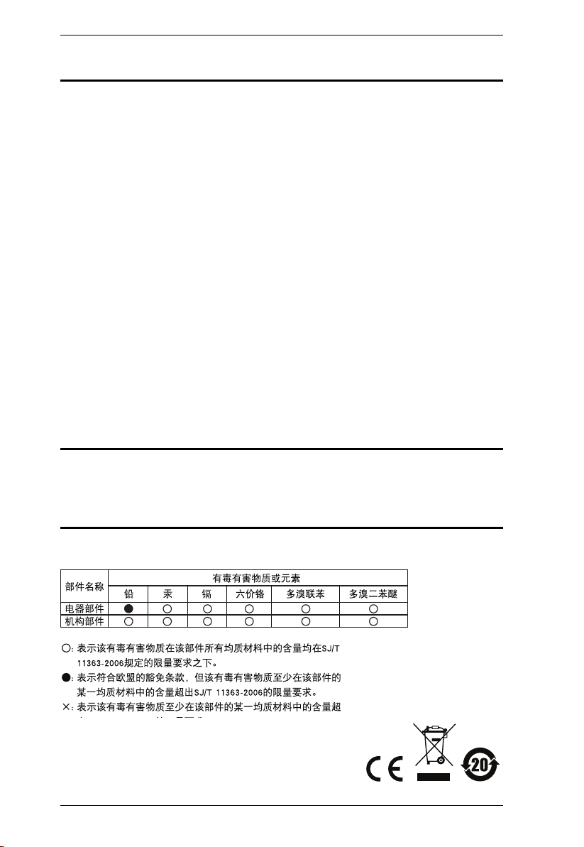
SJ/T 11364-2006
The following contains information that relates to China.
ii
KL1116 User Manual
User Information
Online Registration
Be sure to register your product at our online support center:
International http://eservice.aten.com
Telephone Support
For telephone support, call this number:
International 886-2-8692-6959
China 86-10-5255-0110
Japan 81-3-5615-5811
Korea 82-2-467-6789
North America 1-888-999-ATEN ext 4988
United Kingdom 44-8-4481-58923
User Notice
All information, documentation, and specifications contained in this manual
are subject to change without prior notification by the manufacturer. The
manufacturer makes no representations or warranties, either expressed or
implied, with respect to the contents hereof and specifically disclaims any
warranties as to merchantability or fitness for any particular purpose. Any of
the manufacturer's software described in this manual is sold or licensed as is.
Should the programs prove defective following their purchase, the buyer (and
not the manufacturer, its distributor, or its dealer), assumes the entire cost of all
necessary servicing, repair and any incidental or consequential damages
resulting from any defect in the software.
The manufacturer of this system is not responsible for any radio and/or TV
interference caused by unauthorized modifications to this device. It is the
responsibility of the user to correct such interference.
The manufacturer is not responsible for any damage incurred in the operation
of this system if the correct operational voltage setting was not selected prior
to operation. PLEASE VERIFY THAT THE VOLTAGE SETTING IS
CORRECT BEFORE USE.
iii

KL1116 User Manual
Copyright © 2014 ATEN® International Co., Ltd.
Manual Part No. PAPE-0253-2AXG
Manual Date: 2014-02-27
Altusen and the Altusen logo are registered trademarks of ATEN International Co., Ltd. All rights reserved.
All other brand names and trademarks are the registered property of their respective owners.
Package Contents
Basic Package
The KL1116 package consists of:
1 KL1116 Hideaway
2 Custom KVM Cable Sets
1 Firmware Upgrade Cable
1Power Cord
1 User Manual*
1 Quick Start Guide
1 Registration Card
Optional Equipment
Depending on any optional equipment that you may have purchased, one of the
following may be included in your package:
Standard Rack Mounting Kit - Long
Easy-Installation Rack Mounting Kit - Short
Easy-Installation Rack Mounting Kit - Long
TM
LCD KVM Switch with Standard Rack Mounting Kit
Check to make sure that all of the components are present and in good order.
If anything is missing, or was damaged in shipping, contact your dealer.
Read this manual thoroughly and follow the installation and operation
procedures carefully to prevent any damage to the switch or to any other
devices on the KL1116 installation.
* Features may have been added to the KL1116 since this manual was
published. Please visit our website to download the most up to date version
of the manual.
iv

KL1116 User Manual
Contents
FCC, CE Information. . . . . . . . . . . . . . . . . . . . . . . . . . . . . . . . . . . . . . . . . . ii
SJ/T 11364-2006. . . . . . . . . . . . . . . . . . . . . . . . . . . . . . . . . . . . . . . . . . . . . ii
User Information . . . . . . . . . . . . . . . . . . . . . . . . . . . . . . . . . . . . . . . . . . . . .iii
Online Registration . . . . . . . . . . . . . . . . . . . . . . . . . . . . . . . . . . . . . . . .iii
Telephone Support . . . . . . . . . . . . . . . . . . . . . . . . . . . . . . . . . . . . . . . .iii
User Notice . . . . . . . . . . . . . . . . . . . . . . . . . . . . . . . . . . . . . . . . . . . . . .iii
Package Contents. . . . . . . . . . . . . . . . . . . . . . . . . . . . . . . . . . . . . . . . . . . iv
Basic Package. . . . . . . . . . . . . . . . . . . . . . . . . . . . . . . . . . . . . . . . . . . iv
Optional Equipment. . . . . . . . . . . . . . . . . . . . . . . . . . . . . . . . . . . . . . . iv
About This Manual . . . . . . . . . . . . . . . . . . . . . . . . . . . . . . . . . . . . . . . . . .viii
Overview . . . . . . . . . . . . . . . . . . . . . . . . . . . . . . . . . . . . . . . . . . . . . . .viii
Conventions . . . . . . . . . . . . . . . . . . . . . . . . . . . . . . . . . . . . . . . . . . . . ix
Product Information. . . . . . . . . . . . . . . . . . . . . . . . . . . . . . . . . . . . . . . . . . ix
Chapter 1.
Introduction
Overview . . . . . . . . . . . . . . . . . . . . . . . . . . . . . . . . . . . . . . . . . . . . . . . . . . .1
Features . . . . . . . . . . . . . . . . . . . . . . . . . . . . . . . . . . . . . . . . . . . . . . . . . . . 3
Hardware Requirements . . . . . . . . . . . . . . . . . . . . . . . . . . . . . . . . . . . . . . .4
Computers. . . . . . . . . . . . . . . . . . . . . . . . . . . . . . . . . . . . . . . . . . . . . . . 4
Cables . . . . . . . . . . . . . . . . . . . . . . . . . . . . . . . . . . . . . . . . . . . . . . . . . .4
Front View. . . . . . . . . . . . . . . . . . . . . . . . . . . . . . . . . . . . . . . . . . . . . . . . . .5
Rear View . . . . . . . . . . . . . . . . . . . . . . . . . . . . . . . . . . . . . . . . . . . . . . . . . . 7
Chapter 2.
Hardware Setup
Standard Rack Mounting. . . . . . . . . . . . . . . . . . . . . . . . . . . . . . . . . . . . . . .9
Single Stage Installation . . . . . . . . . . . . . . . . . . . . . . . . . . . . . . . . . . . . . . 11
Daisy Chain Installation. . . . . . . . . . . . . . . . . . . . . . . . . . . . . . . . . . . . . . .13
Chapter 3.
Basic Operation
Opening the Console . . . . . . . . . . . . . . . . . . . . . . . . . . . . . . . . . . . . . . . . 15
Opening Separately. . . . . . . . . . . . . . . . . . . . . . . . . . . . . . . . . . . . . . .15
Opening Together . . . . . . . . . . . . . . . . . . . . . . . . . . . . . . . . . . . . . . . .17
Operating Precautions. . . . . . . . . . . . . . . . . . . . . . . . . . . . . . . . . . . . .18
Closing the Console . . . . . . . . . . . . . . . . . . . . . . . . . . . . . . . . . . . . . . . . .19
Closing Separately . . . . . . . . . . . . . . . . . . . . . . . . . . . . . . . . . . . . . . .19
Closing Together . . . . . . . . . . . . . . . . . . . . . . . . . . . . . . . . . . . . . . . . .21
LCD OSD Configuration . . . . . . . . . . . . . . . . . . . . . . . . . . . . . . . . . . . . . .22
The LCD Buttons. . . . . . . . . . . . . . . . . . . . . . . . . . . . . . . . . . . . . . . . .22
LCD Adjustment Settings . . . . . . . . . . . . . . . . . . . . . . . . . . . . . . . . . . 23
Port Selection . . . . . . . . . . . . . . . . . . . . . . . . . . . . . . . . . . . . . . . . . . . . . . 24
Manual Port Switching. . . . . . . . . . . . . . . . . . . . . . . . . . . . . . . . . . . . . 24
v

KL1116 User Manual
Hot Plugging . . . . . . . . . . . . . . . . . . . . . . . . . . . . . . . . . . . . . . . . . . . . . . . 25
Switching Station Positions. . . . . . . . . . . . . . . . . . . . . . . . . . . . . . . . . 25
Hot Plugging Ports . . . . . . . . . . . . . . . . . . . . . . . . . . . . . . . . . . . . . . . 25
Powering Off and Restarting. . . . . . . . . . . . . . . . . . . . . . . . . . . . . . . . . . . 25
Port ID Numbering . . . . . . . . . . . . . . . . . . . . . . . . . . . . . . . . . . . . . . . . . . 26
Chapter 4.
OSD Operation
OSD Overview . . . . . . . . . . . . . . . . . . . . . . . . . . . . . . . . . . . . . . . . . . . . . 27
OSD Navigation . . . . . . . . . . . . . . . . . . . . . . . . . . . . . . . . . . . . . . . . . . . . 29
OSD Main Screen Headings. . . . . . . . . . . . . . . . . . . . . . . . . . . . . . . . . . . 29
OSD Functions . . . . . . . . . . . . . . . . . . . . . . . . . . . . . . . . . . . . . . . . . . . . . 30
F1 GOTO . . . . . . . . . . . . . . . . . . . . . . . . . . . . . . . . . . . . . . . . . . . . . . 30
F2 LIST . . . . . . . . . . . . . . . . . . . . . . . . . . . . . . . . . . . . . . . . . . . . . . . . 31
F3 SET . . . . . . . . . . . . . . . . . . . . . . . . . . . . . . . . . . . . . . . . . . . . . . . . 32
F4 ADM. . . . . . . . . . . . . . . . . . . . . . . . . . . . . . . . . . . . . . . . . . . . . . . . 34
F5 SKP . . . . . . . . . . . . . . . . . . . . . . . . . . . . . . . . . . . . . . . . . . . . . . . . 38
F6 BRC . . . . . . . . . . . . . . . . . . . . . . . . . . . . . . . . . . . . . . . . . . . . . . . . 38
F7 SCAN. . . . . . . . . . . . . . . . . . . . . . . . . . . . . . . . . . . . . . . . . . . . . . . 39
F8 LOUT . . . . . . . . . . . . . . . . . . . . . . . . . . . . . . . . . . . . . . . . . . . . . . . 40
Chapter 5.
Keyboard Port Operation
Invoking Hotkey Mode (HKM). . . . . . . . . . . . . . . . . . . . . . . . . . . . . . . . . . 41
When Hotkey Mode is active: . . . . . . . . . . . . . . . . . . . . . . . . . . . . 41
Hotkey Port Access . . . . . . . . . . . . . . . . . . . . . . . . . . . . . . . . . . . . . . . . . 42
Selecting the Active Port. . . . . . . . . . . . . . . . . . . . . . . . . . . . . . . . . . . 42
Auto Scanning. . . . . . . . . . . . . . . . . . . . . . . . . . . . . . . . . . . . . . . . . . . 43
Setting the Scan Interval . . . . . . . . . . . . . . . . . . . . . . . . . . . . . . . . 43
Invoking Auto Scan Mode . . . . . . . . . . . . . . . . . . . . . . . . . . . . . . . 44
Pausing Auto Scan:. . . . . . . . . . . . . . . . . . . . . . . . . . . . . . . . . . . . 44
Skip Mode . . . . . . . . . . . . . . . . . . . . . . . . . . . . . . . . . . . . . . . . . . . . . . 45
Beeper Control . . . . . . . . . . . . . . . . . . . . . . . . . . . . . . . . . . . . . . . . . . . . . 46
Hotkey Summary Table . . . . . . . . . . . . . . . . . . . . . . . . . . . . . . . . . . . . . . 46
Chapter 6.
The Firmware Upgrade Utility
Preparation . . . . . . . . . . . . . . . . . . . . . . . . . . . . . . . . . . . . . . . . . . . . . . . . 48
Starting the Upgrade. . . . . . . . . . . . . . . . . . . . . . . . . . . . . . . . . . . . . . . . . 49
Upgrade Succeeded . . . . . . . . . . . . . . . . . . . . . . . . . . . . . . . . . . . . . . 51
Upgrade Failed . . . . . . . . . . . . . . . . . . . . . . . . . . . . . . . . . . . . . . . . . . 52
Firmware Upgrade Recovery . . . . . . . . . . . . . . . . . . . . . . . . . . . . . . . . . . 52
Appendix
Safety Instructions . . . . . . . . . . . . . . . . . . . . . . . . . . . . . . . . . . . . . . . . . . 53
General . . . . . . . . . . . . . . . . . . . . . . . . . . . . . . . . . . . . . . . . . . . . . . . . 53
vi

KL1116 User Manual
Rack Mounting . . . . . . . . . . . . . . . . . . . . . . . . . . . . . . . . . . . . . . . . . .55
Consignes de sécurité. . . . . . . . . . . . . . . . . . . . . . . . . . . . . . . . . . . . . . . .56
Général . . . . . . . . . . . . . . . . . . . . . . . . . . . . . . . . . . . . . . . . . . . . . . . .56
Montage sur bâti . . . . . . . . . . . . . . . . . . . . . . . . . . . . . . . . . . . . . . . . .59
Technical Support . . . . . . . . . . . . . . . . . . . . . . . . . . . . . . . . . . . . . . . . . . .60
International. . . . . . . . . . . . . . . . . . . . . . . . . . . . . . . . . . . . . . . . . . . . . 60
North America . . . . . . . . . . . . . . . . . . . . . . . . . . . . . . . . . . . . . . . . . . .60
Specifications . . . . . . . . . . . . . . . . . . . . . . . . . . . . . . . . . . . . . . . . . . . . . .61
OSD Factory Default Settings. . . . . . . . . . . . . . . . . . . . . . . . . . . . . . . . . .62
Connection Table . . . . . . . . . . . . . . . . . . . . . . . . . . . . . . . . . . . . . . . . . . .62
Clear Login Information. . . . . . . . . . . . . . . . . . . . . . . . . . . . . . . . . . . . . . .63
Optional Rack Mounting . . . . . . . . . . . . . . . . . . . . . . . . . . . . . . . . . . . . . .64
Troubleshooting . . . . . . . . . . . . . . . . . . . . . . . . . . . . . . . . . . . . . . . . . . . .68
Overview . . . . . . . . . . . . . . . . . . . . . . . . . . . . . . . . . . . . . . . . . . . . . . .68
Dedicated Invocation Keys . . . . . . . . . . . . . . . . . . . . . . . . . . . . . . . . . . . .68
About SPHD Connectors . . . . . . . . . . . . . . . . . . . . . . . . . . . . . . . . . . . . .68
Limited Warranty . . . . . . . . . . . . . . . . . . . . . . . . . . . . . . . . . . . . . . . . . . . .69
vii

KL1116 User Manual
About This Manual
This User Manual is provided to help you get the most from your KL1116
system. It covers all aspects of installation, configuration and operation. An
overview of the information found in the manual is provided below.
Overview
Chapter 1, Introduction, introduces you to the KL1116 System. Its
purpose, features and benefits are presented, and its front and back panel
components are described.
Chapter 2, Hardware Setup, provides step-by-step instructions for setting
up your installation, and explains some basic operation procedures.
Chapter 3, Basic Operation, explains the fundamental concepts involved
in operating the KL1116.
Chapter 4, OSD Operation, provides a complete description of the
KL1116 OSD (On Screen Display), and how to work with it.
Chapter 5, Keyboard Port Operation, explains the concepts and
procedures used to control the KL1116 from the keyboard.
Chapter 6, The Firmware Upgrade Utility, explains how to use this
utility to upgrade the KL1116’s firmware with the latest available versions.
An Appendix, at the end of the manual provides technical and
troubleshooting information.
viii
Conventions
This manual uses the following conventions:
Monospaced Indicates text that you should key in.
[ ] Indicates keys you should press. For example, [Enter] means to
press the Enter key. If keys need to be chorded, they appear
together in the same bracket with a plus sign between them:
[Ctrl+Alt].
1. Numbered lists represent procedures with sequential steps.
♦ Bullet lists provide information, but do not involve sequential steps.
→ Indicates selecting the option (on a menu or dialog box, for
example), that comes next. For example, Start
open the Start menu, and then select Run.
Indicates critical information.
Product Information
KL1116 User Manual
→ Run means to
For information about all ATEN products and how they can help you connect
without limits, visit ATEN on the Web or contact an ATEN Authorized
Reseller. Visit ATEN on the Web for a list of locations and telephone numbers:
International http://www.aten.com
North America http://www.aten-usa.com
ix

KL1116 User Manual
This Page Intentionally Left Blank
x

Chapter 1
Introduction
Overview
The KL1116 KVM Switch is a control unit that allows access to multiple
computers from a single KVM (keyboard, monitor, and mouse), console.
Before the development of the Master View, the only way to control multiple
computer configurations from a single console was through a complex and
costly network system. Now, with the KL1116, you can easily access multiple
computers in a cost effective manner.
A single KL1116 can control up to 16 computers. As many as 31 additional
units can be daisy chained to each other, so that up to 512 (KL1116 + KH0116)
computers can all be controlled from a single keyboard-monitor-mouse
console.
The KL1116 offers a space-saving, streamlined approach to KVM switch
technology by integrating a keyboard, LCD monitor, and touchpad in a
Hideaway™ housing. The LCD display is built into the cover; the keyboard
and touchpad are built into the base. Slide the LCD and keyboard modules out;
flip the cover up; and you are ready to go to work. When finished, flip the cover
down and slide the modules away. The LCD module and keyboard module
slide separately – you can see the video display, for example, while the
keyboard and touchpad are conveniently out of the way.
For further convenience, the Hideaway™ housing is slightly less than 1U high
for easy installation and manipulation in a 1U rack. The KL1116 also features
high density 15 pin connectors instead of the usual 25 pin connectors. This
space-saving innovation allows a full, 16 port switch to be installed in a 1U
system rack. Because of its modular design, the KVM section can be detached
from the switch section.
Your KL1116 investment is protected by an included Firmware Upgrade
Utility. You can stay current with the latest functionality improvements by
downloading firmware update files from our website as they become available,
and using the utility to quickly and conveniently perform the upgrade.
Setup is fast and easy; plugging cables into their appropriate ports is all that is
entailed. Because the KL1116 intercepts keyboard input directly, there is no
software to configure; no need to get involved in complex installation routines;
nor any need to be concerned with incompatibility problems.
1

KL1116 User Manual
Access to any computer connected to the installation is easily accomplished
either by means of a powerful, mouse driven, OSD (On Screen Display) menu
system, or by entering Hotkey combinations from the keyboard. A convenient
Auto Scan feature also permits automatic scanning and monitoring of the
activities of all computers running on the installation one by one.
There is no better way to save time and money than with a KL1116 installation.
By using the KL1116 with its Hideaway™ console to manage your installation,
you: (1) eliminate the expense of having to purchase a separate keyboard,
monitor, and mouse for each computer; (2) save all the space those extra
components would take up; (3) save the space that a keyboard, monitor, and
mouse would take with a standard KVM switch; (4) save on energy costs; and
(5) eliminate the inconvenience and wasted effort involved in constantly
moving from one computer to another.
2

Chapter 1. Introduction
Features
Integrated KVM console with 15" or 17" LCD monitor - in a Hideaway™
housing.
Hideaway™ housing is slightly less than 1U - with top and bottom
clearance for smooth operation in a 1U high system rack.
LCD Monitor component can slide independently of the keyboard/
touchpad component
Space saving technology - two consoles (one bus) control up to 16
computers.
Daisy chain up to 31 additional units to control up to 512 computers from
the switch's integrated Hideaway™ console.
No software required - convenient computer selection via mouse driven
intuitive On Screen Display (OSD) menus and Hotkeys.
Auto Scan feature for monitoring user-selected computers.
Broadcast support - commands from the keyboard can be broadcast to all
available computers on the installation.
Hot Pluggable - add or remove computers without having to power down
the switch.
Two level password security - only authorized users view and control the
computers - up to four users plus an administrator with separate profiles
for each.
DDC Emulation of the LCD Monitor - VGA settings of every connected
computer are automatically adjusted for optimal output to the LCD
Monitor.
Upgradable firmware.
Supports Windows, Linux, Unix, Netware, AIX (RS6000), DOS 6.2 and
higher.
3
KL1116 User Manual
Hardware Requirements
Computers
The integrated LCD monitor's maximum resolution is 1024 x 768 (15") or
1280 x 1024 (17"). Make sure that none of the computer resolution settings
exceed the LCD monitor's maximum resolution.
Cables
Substandard cables may damage the connected devices or degrade overall
performance. For optimum signal integrity and to simplify the layout, we
strongly recommend that you use the high quality CS Custom Cable sets
described below:
Function CS Part Number
KVM Switch to KVM Switch (Daisy Chaining) 2L-1700 - 0.6 m
KVM Switch to Computer (PS/2 Connection) 2L-5201P - 1.2 m
KVM Switch to Computer (USB Connection) 2L-5202UP - 1.8 m
2L-1701 - 1.8 m
2L-5202P - 1.8 m
2L-5203P - 3.0 m
2L-5206P - 6.0 m
2L-5203UP - 3.0 m
2L-5206UP - 6.0 m
Note: 1. The KL1116 does not support serial mice. You cannot use Serial-to-
PS/2 adapters with the cables. Attempts to do so will not work.
2. The KL1116 supports the installation of a local external console. If
you install an external console and wish to extend the distance
between it and the switch, CS Custom extender cables are available
in various lengths. Contact your dealer for details.
4
Front View
2
3
4
5
6
Chapter 1. Introduction
1
12
11
10
7
8
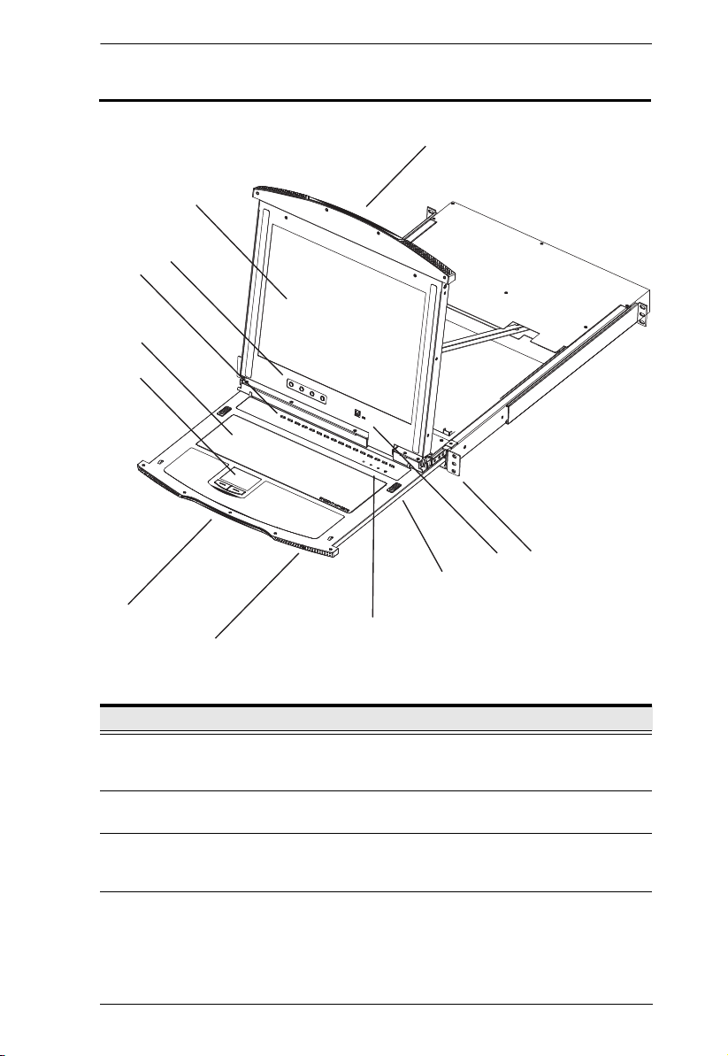
No. Component Description
1 Upper
Handle
2 LCD Display After sliding the LCD module out, flip up the cover to access the
3 LCD Controls Buttons to control the position and picture settings of the LCD
Pull to slide the LCD module out; push to slide the module in.
See item 7 in this table and Opening the Console, page 15 for
more details on sliding the console in and out.
LCD monitor.
display are located here. See The LCD Buttons, page 22, for
details.
9
(Continues on next page.)
5

KL1116 User Manual
(Continued from previous page.)
No. Component Description
4Port
Switches
and Port
LEDs
Press a switch to bring the KVM focus to the computer attached
to its corresponding port. See Manual Port Switching, page 24
for details.
Two Port LEDs are built into the Port Switches. The one on the
left is the On Line LED; the one on the right is the Selected Port
LED:
An On Line LED lights GREEN to indicate that the computer
attached to its corresponding port is up and running.
A Selected LED lights ORANGE to indicate that the computer
attached to its corresponding port is the one that has the KVM
focus. The LED is steady under normal conditions, but flashes
when its port is accessed under Auto Scan Mode (see
page 39).
5 Keyboard Standard 105-key keyboard.
6 Touchpad Standard mouse touchpad.
7 Lower
Handle
8 Power LED Lights BLUE to indicate that the unit is receiving power.
9 Lock LEDs &
Reset Switch
Pull to slide the keyboard and touchpad module out. See item 1
in this table and Opening the Console, page 15 for more details
on sliding the console in and out.
The Num Lock, Caps Lock, Scroll Lock LEDs are located
here.
A Reset Switch is located just to the right of the Lock LEDs.
Press this recessed switch in with a thin object to perform a
system reset.
10 Release
Catch
11 Firmware
Upgrade
Section
These catches (one on each side of the keyboard) release the
keyboard and touchpad module so you can slide it away.
Firmware Upgrade Port: The Firmware Upgrade Cable that
transfers the firmware upgrade data from the administrator's
computer to the KL1116 plugs into this RJ-11 connector.
Firmware Upgrade Switch: During normal operation this
switch should be in the NORMAL position. (The Firmware
Upgrade Utility, page 47 for more details.)
12 Rack
Mounting
Brackets
The rack mounting brackets located at each corner of the unit
secure the chassis to a system rack. See Standard Rack
Mounting, page 9 for details.
6
Chapter 1. Introduction
1
2
3
4
5
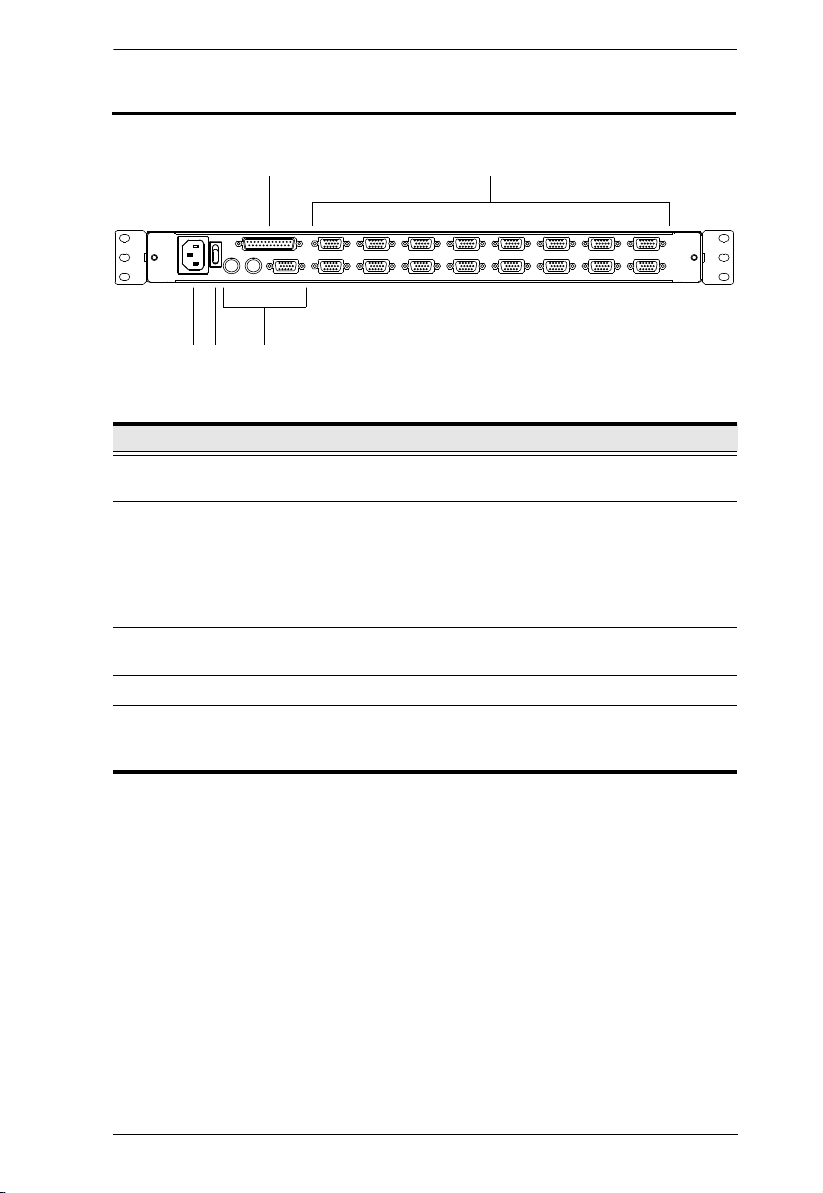
Rear View
No. Component Description
1 Daisy Chain
Port
2 KVM Ports The cables that link to the computers plug in here.
3 Power
Socket
4 Power Switch This is a standard rocker switch that powers the unit On and Off.
5 External
Console
Section
When daisy chaining units, the cable plugs in here.
Note: The shape of these 15-pin connectors has been
specifically modified so that only KVM cables designed to work
with this switch can plug in (See Cables, page 4). Do NOT
attempt to use ordinary 15 pin VGA connector cables to link
these ports to the computers.
This is a standard 3 prong AC power socket. The power cord
from an AC source plugs in here.
For flexibility and convenience, the KL1116 supports an
independent, external, KVM console. The external console's
keyboard, monitor, and mouse cables plug in here.
7

KL1116 User Manual
This Page Intentionally Left Blank
8
Chapter 2
1. Important safety information regarding the placement of this
device is provided on page 53. Please review it before proceeding.
2. Make sure that power to all the devices you will be connecting up
have been turned off. You must unplug the power cords of any
computers that have the Keyboard Power On function.
Hardware Setup
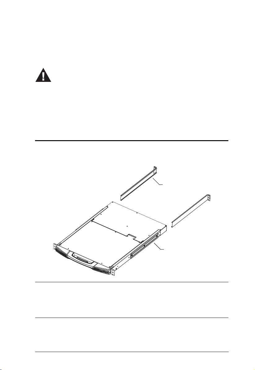
Standard Rack Mounting
A standard rack mounting kit is provided with your KL1116. The kit enables
the switch to be mounted in rack with a depth of 42–77 cm.
L Brackets
Side Mountng
Brackets
Note: 1. It takes two people to mount the switch: one to hold it in place; the
other to screw it in.
2. The standard rack mounting kit does not include screws or cage nuts.
If you need additional screws or cage nuts, contact your rack dealer.
9
KL1116 User Manual
Optional mounting kits – including single person Easy Installation kits – are
available with a separate purchase. See Optional Rack Mounting, page 64 for
details.
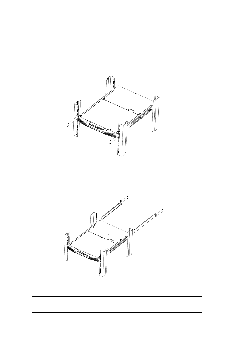
To rack mount the KL1116, do the following:
1. While one person positions the KL1116 in the rack and holds it in place,
the second person loosely screws the front brackets to the rack.
2. While the first person still holds the KL1116 in place, the second person
slides the L brackets into the KL1116's side mounting brackets from the
rear until the bracket flanges contact the rack, then screws the L brackets
to the rack.
3. After the L brackets have been secured, tighten the front bracket screws.
Note: Allow at least 5.1 cm on each side for proper ventilation, and at least
12.7 cm at the back for the power cord and cable clearance.
10

Chapter 2. Hardware Setup
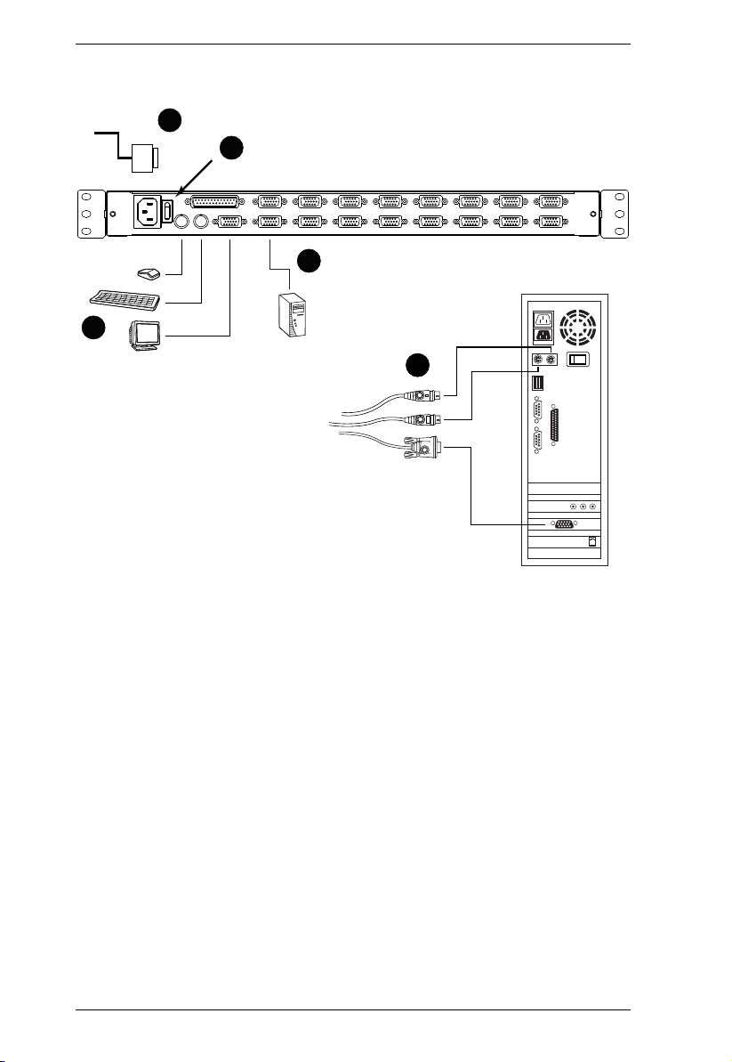
Single Stage Installation
In a Single Stage installation, there are no additional switches daisy chained
down from the first unit. To set up a single stage installation, refer to the
installation diagram on the next page (the numbers in the diagram correspond
to the numbers of the installation steps), and do the following:
1. Plug your external console's keyboard, monitor, and mouse into the
Console Ports located on the switch's rear panel. The ports are color coded
and marked with an appropriate icon to indicate themselves.
Note: This step is optional.
2. For each of the computers you are installing, use a KVM cable set (as
described in the Cables section on page 4), to connect any available KVM
Port to the computer's keyboard, video and mouse ports.
Note: Ignore the daisy chain port at this time. It is only used when daisy
chaining additional KH0116 units. Daisy chaining is described in
the next section.
3. Use the Power cord provided with this package to connect the switch's
Power Socket to an AC power source.
4. Power on the switch.
5. After the switch is powered on, power on the computers.
11
KL1116 User Manual
Single Stage Installation Diagram
3
4
2
1
2
12

Chapter 2. Hardware Setup
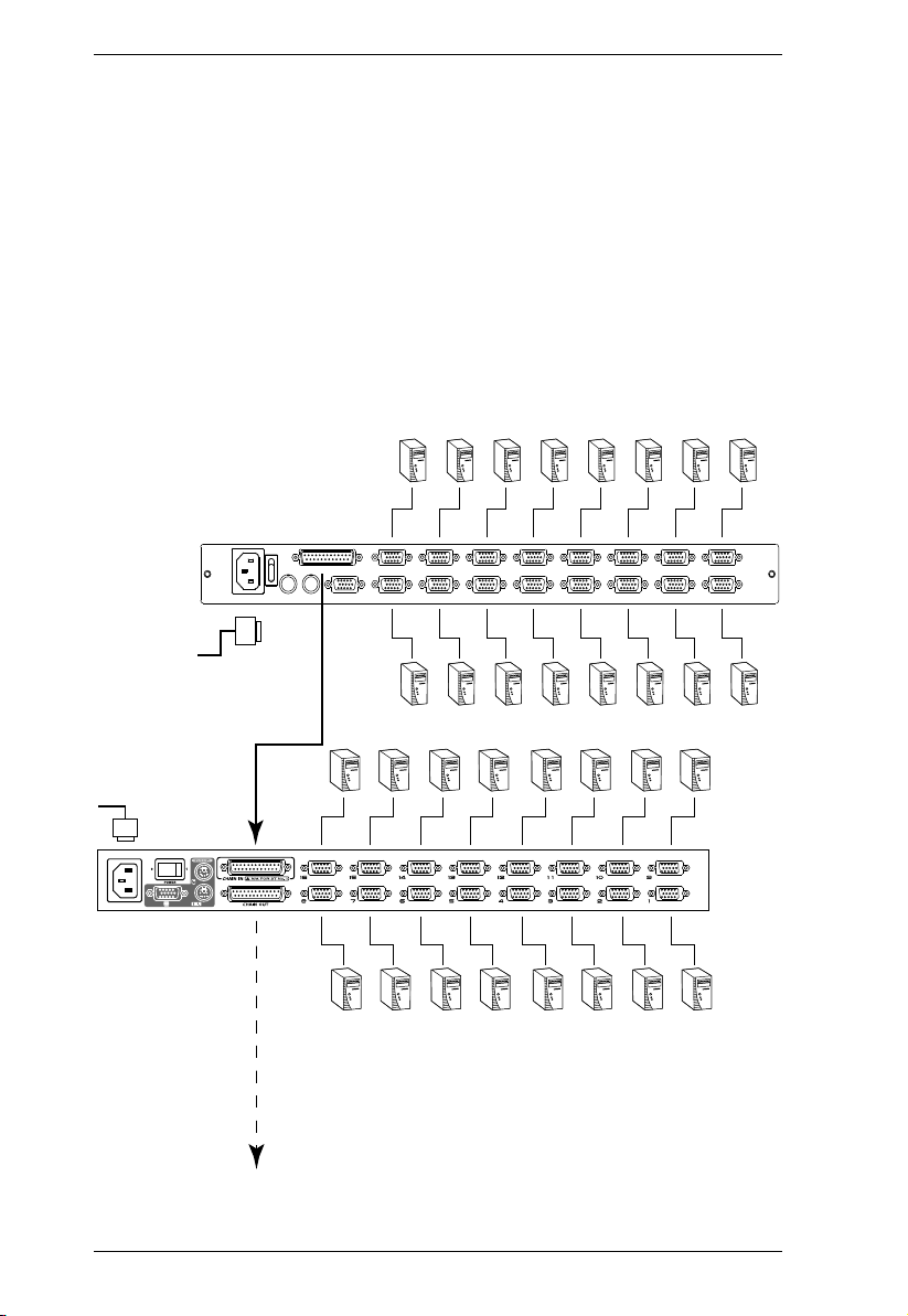
Daisy Chain Installation
To control even more computers, up to 31 KH0116 units can be daisy chained
down from the KL1116.
Note: It would be unnecessarily wasteful and expensive to use KL1116
switches for daisy chaining since there is no point in having consoles on
the chained switches. Therefore, KH0116 switches are used instead.
The KH0116 is similar to the KL1116, except that it comes in a standard
housing without the built in Hideaway™ console.
As many as 512 computers can be controlled from the unit's integrated
Hideaway™ console in a complete installation. A table showing the relation
between the number of computers and the number of KH0116 units needed to
control them is provided on page 62 in the Appendix.
To set up a daisy chained installation, refer to the daisy chain installation
diagram on the following page, and do the following:
1. Make sure that power to all the devices you will be connecting up has been
turned off.
2. Use a daisy chain cable set (described in the Cables section on page 4) to
connect the Chain Out port of the parent unit to the Chain In port of the
child unit (First Station Out to Second Station In, Second Station Out to
Third Station In, etc.).
3. Use KVM cable sets (described in the Cables section of the KH0116 User
Manual), to connect any available KVM Port on the daisy chained switch
to the keyboard, video and mouse ports of the computers you are
installing.
4. Repeat the above steps for any additional KH0116 units you wish to add to
the chain.
5. Power up the installation according to the following procedure:
a) Power on the First Station (KL1116). Wait a few seconds for the unit to
ascertain its Station ID.
(Continues on next page.)
13
KL1116 User Manual
KL1116
KH0116
(Continued from previous page.)
b) Power up each daisy chained station on the installation in turn (Second
Station, then Third Station, etc.). Each KH0116 has an LED display on
its front panel to indicate its Station ID (the Station ID for the First
Stage unit (KL1116) is 01, the ID for the Second Stage unit (the first
KH0116) is 02, the ID for the Third Stage unit is 03, etc.). In each case,
wait for the Station ID to be ascertained and displayed on the Station ID
LED before plugging in the next Station.
c) After all the stations are up, power on the computers.
Daisy Chain Installation Diagram
14
Chapter 3
Basic Operation
Opening the Console
The KL1116's console consists of two modules: An LCD display module
located under the top cover, and a keyboard / touchpad module below the LCD
module.
The modules can either slide together, or independently. This allows you to
have the LCD display available for viewing while the keyboard / touchpad
module is conveniently out of the way when not in use.
As a safety precaution, to keep the console from accidentally sliding out, it is
locked into the In position. Before you can pull it out, you must release it by
pushing the catches on the unit's front panel toward the center of the switch.
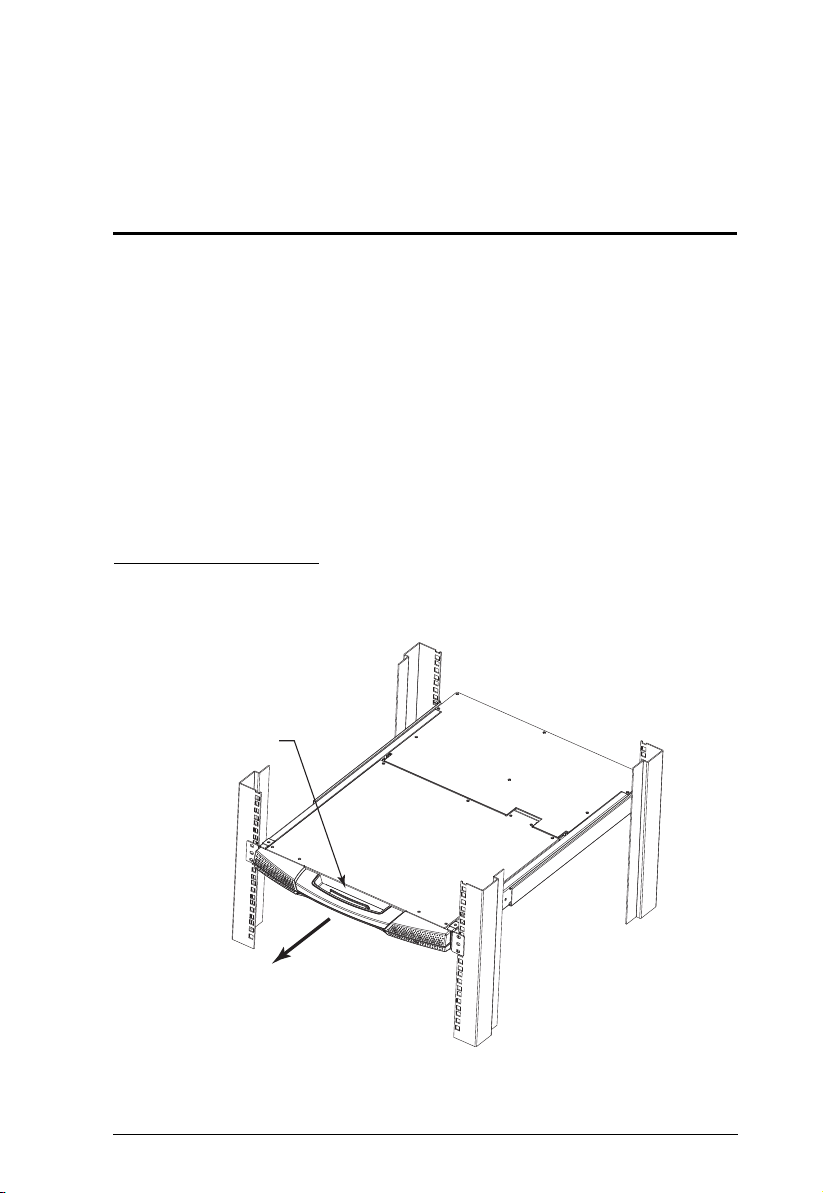
Opening Separately
1. Release the LCD module by pulling the release catch into the handle as
you pull the module toward you.
Release Catch
15
 Loading...