

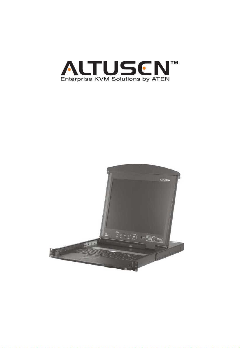
Dual Rail LCD PS/2 - USB Console
KL1100
User Manual
www.aten.com
KL1100 User Manual
FCC Information
This is an FCC Class A product. In a domestic environment this product may
cause radio interference in which case the user may be required to take
adequate measures.
This equipment has been tested and found to comply with the limits for a Class
A digital device, pursuant to Part 15 of the FCC Rules. These limits are
designed to provide reasonable protection against harmful interference when
the equipment is operated in a commercial environment. This equipment
generates, uses and can radiate radio frequency energy and, if not installed and
used in accordance with the instruction manual, may cause harmful
interference to radio communications. Operation of this equipment in a
residential area is likely to cause harmful interference in which case the user
will be required to correct the interference at his own expense.
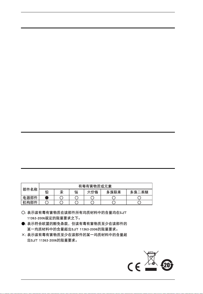
RoHS
This product is RoHS compliant.
SJ/T 11364-2006
The following contains information that relates to China.
ii
User Information
Online Registration
Be sure to register your product at our online support center:
International http://support.aten.com
North America http://www.aten-usa.com/product_registration
Telephone Support
For telephone support, call this number:
International 886-2-8692-6959
China 86-10-5255-0110
Japan 81-3-5323-7178
Korea 82-2-467-6789
North America 1-888-999-ATEN ext 4988
United Kingdom 44-8-4481-58923
KL1100 User Manual
User Notice
All information, documentation, and specifications contained in this manual
are subject to change without prior notification by the manufacturer. The
manufacturer makes no representations or warranties, either expressed or
implied, with respect to the contents hereof and specifically disclaims any
warranties as to merchantability or fitness for any particular purpose. Any of
the manufacturer's software described in this manual is sold or licensed `as is'.
Should the programs prove defective following their purchase, the buyer (and
not the manufacturer, its distributor, or its dealer), assumes the entire cost of all
necessary servicing, repair and any incidental or consequential damages
resulting from any defect in the software.
The manufacturer of this system is not responsible for any radio and/or TV
interference caused by unauthorized modifications to this device. It is the
responsibility of the user to correct such interference.
The manufacturer is not responsible for any damage incurred in the operation
of this system if the correct operational voltage setting was not selected prior
to operation. PLEASE VERIFY THAT THE VOLTAGE SETTING IS
CORRECT BEFORE USE.
iii

KL1100 User Manual
Copyright © 2008 ATEN® International Co., Ltd.
Manual Part No. PAPE-0275-AX2G
Manual Date:2010-10-29
Altusen and the Altusen logo are registered trademarks of ATEN International Co., Ltd. All rights
reserved. All other brand names and trademarks are the registered property of their respective owners.
Package Contents
The KL1100 package consists of:
1 KL1100 Dual Rail LCD PS/2 - USB Console
with Standard Rack Mount Kit
1 Custom KVM Cable
1 Power Cord (AC power models only)
1 Firmware Upgrade Cable
1 User Manual*
1 Quick Start Guide
Check to make sure that all of the components are present and in good order.
If anything is missing, or was damaged in shipping, contact your dealer.
Read this manual thoroughly and follow the installation and operation
procedures carefully to prevent any damage to the console or to any other
devices on the KL1100 installation.
* Changes may have been made to the manual since it was printed. Please visit
our web site to download the most up to date version of the manual.
iv

KL1100 User Manual
Contents
FCC Information . . . . . . . . . . . . . . . . . . . . . . . . . . . . . . . . . . . . . . . . . . . . .ii
SJ/T 11364-2006. . . . . . . . . . . . . . . . . . . . . . . . . . . . . . . . . . . . . . . . . . . . .ii
User Information . . . . . . . . . . . . . . . . . . . . . . . . . . . . . . . . . . . . . . . . . . . . .iii
Online Registration . . . . . . . . . . . . . . . . . . . . . . . . . . . . . . . . . . . . . . . .iii
Telephone Support . . . . . . . . . . . . . . . . . . . . . . . . . . . . . . . . . . . . . . . .iii
User Notice . . . . . . . . . . . . . . . . . . . . . . . . . . . . . . . . . . . . . . . . . . . . . .iii
Package Contents. . . . . . . . . . . . . . . . . . . . . . . . . . . . . . . . . . . . . . . . . . . iv
About This Manual . . . . . . . . . . . . . . . . . . . . . . . . . . . . . . . . . . . . . . . . . . vii
Overview . . . . . . . . . . . . . . . . . . . . . . . . . . . . . . . . . . . . . . . . . . . . . . . vii
Conventions . . . . . . . . . . . . . . . . . . . . . . . . . . . . . . . . . . . . . . . . . . . .viii
Product Information. . . . . . . . . . . . . . . . . . . . . . . . . . . . . . . . . . . . . . . . . . viii
Chapter 1.
Introduction
Overview. . . . . . . . . . . . . . . . . . . . . . . . . . . . . . . . . . . . . . . . . . . . . . . . . . .1
Features . . . . . . . . . . . . . . . . . . . . . . . . . . . . . . . . . . . . . . . . . . . . . . . . . . .2
Requirements . . . . . . . . . . . . . . . . . . . . . . . . . . . . . . . . . . . . . . . . . . . . . . .3
LCD Console. . . . . . . . . . . . . . . . . . . . . . . . . . . . . . . . . . . . . . . . . . . . . 3
External Console. . . . . . . . . . . . . . . . . . . . . . . . . . . . . . . . . . . . . . . . . .3
Cables. . . . . . . . . . . . . . . . . . . . . . . . . . . . . . . . . . . . . . . . . . . . . . . . . .3
Operating Systems . . . . . . . . . . . . . . . . . . . . . . . . . . . . . . . . . . . . . . . .4
Components . . . . . . . . . . . . . . . . . . . . . . . . . . . . . . . . . . . . . . . . . . . . . . . .5
Front View. . . . . . . . . . . . . . . . . . . . . . . . . . . . . . . . . . . . . . . . . . . . . . .5
Keyboard Module . . . . . . . . . . . . . . . . . . . . . . . . . . . . . . . . . . . . . . . . .6
LCD Module . . . . . . . . . . . . . . . . . . . . . . . . . . . . . . . . . . . . . . . . . . . . .7
Rear View (AC Power) . . . . . . . . . . . . . . . . . . . . . . . . . . . . . . . . . . . . .8
Rear View (DC Power) . . . . . . . . . . . . . . . . . . . . . . . . . . . . . . . . . . . . .9
Chapter 2.
Hardware Setup
Before you Begin. . . . . . . . . . . . . . . . . . . . . . . . . . . . . . . . . . . . . . . . . . . .11
Standard Rack Mounting. . . . . . . . . . . . . . . . . . . . . . . . . . . . . . . . . . . . . .12
Connecting Up . . . . . . . . . . . . . . . . . . . . . . . . . . . . . . . . . . . . . . . . . . . . .14
Chapter 3.
Operation
Opening the Console . . . . . . . . . . . . . . . . . . . . . . . . . . . . . . . . . . . . . . . .15
Opening Separately. . . . . . . . . . . . . . . . . . . . . . . . . . . . . . . . . . . . . . .15
Opening Together . . . . . . . . . . . . . . . . . . . . . . . . . . . . . . . . . . . . . . . .17
Operating Precautions. . . . . . . . . . . . . . . . . . . . . . . . . . . . . . . . . . . . .18
Closing the Console . . . . . . . . . . . . . . . . . . . . . . . . . . . . . . . . . . . . . . . . .19
Hot Plugging . . . . . . . . . . . . . . . . . . . . . . . . . . . . . . . . . . . . . . . . . . . . . . .21
Powering Off and Restarting. . . . . . . . . . . . . . . . . . . . . . . . . . . . . . . . . . .21
v

KL1100 User Manual
LCD OSD Configuration . . . . . . . . . . . . . . . . . . . . . . . . . . . . . . . . . . . . . .22
The LCD Buttons. . . . . . . . . . . . . . . . . . . . . . . . . . . . . . . . . . . . . . . . .22
LCD Adjustment Settings . . . . . . . . . . . . . . . . . . . . . . . . . . . . . . . . . .23
Console Selection . . . . . . . . . . . . . . . . . . . . . . . . . . . . . . . . . . . . . . . . . . .24
Chapter 4.
Firmware Upgrade
The Firmware Upgrade Utility. . . . . . . . . . . . . . . . . . . . . . . . . . . . . . . . . .25
Before You Begin . . . . . . . . . . . . . . . . . . . . . . . . . . . . . . . . . . . . . . . .25
Firmware Upgrade Mode . . . . . . . . . . . . . . . . . . . . . . . . . . . . . . . . . .26
Performing the Upgrade . . . . . . . . . . . . . . . . . . . . . . . . . . . . . . . . . . . 27
Upgrade Succeeded:. . . . . . . . . . . . . . . . . . . . . . . . . . . . . . . . . . . 29
Upgrade Failed:. . . . . . . . . . . . . . . . . . . . . . . . . . . . . . . . . . . . . . . 30
Firmware Upgrade Recovery . . . . . . . . . . . . . . . . . . . . . . . . . . . . . . .31
Exiting Firmware Upgrade Mode. . . . . . . . . . . . . . . . . . . . . . . . . . . . .31
Appendix
Safety Instructions . . . . . . . . . . . . . . . . . . . . . . . . . . . . . . . . . . . . . . . . . .33
General . . . . . . . . . . . . . . . . . . . . . . . . . . . . . . . . . . . . . . . . . . . . . . . .33
DC Power . . . . . . . . . . . . . . . . . . . . . . . . . . . . . . . . . . . . . . . . . . . . . .35
Rack Mounting . . . . . . . . . . . . . . . . . . . . . . . . . . . . . . . . . . . . . . . . . . 36
Technical Support. . . . . . . . . . . . . . . . . . . . . . . . . . . . . . . . . . . . . . . . . . .37
International . . . . . . . . . . . . . . . . . . . . . . . . . . . . . . . . . . . . . . . . . . . . 37
North America. . . . . . . . . . . . . . . . . . . . . . . . . . . . . . . . . . . . . . . . . . .37
Specifications . . . . . . . . . . . . . . . . . . . . . . . . . . . . . . . . . . . . . . . . . . . . . .38
AC Power Models . . . . . . . . . . . . . . . . . . . . . . . . . . . . . . . . . . . . . . . .38
DC Power Models. . . . . . . . . . . . . . . . . . . . . . . . . . . . . . . . . . . . . . . .39
Optional Rack Mounting . . . . . . . . . . . . . . . . . . . . . . . . . . . . . . . . . . . . . .40
Sun Keyboard Emulation . . . . . . . . . . . . . . . . . . . . . . . . . . . . . . . . . . . . .44
Troubleshooting . . . . . . . . . . . . . . . . . . . . . . . . . . . . . . . . . . . . . . . . . . . .45
About SPHD Connectors . . . . . . . . . . . . . . . . . . . . . . . . . . . . . . . . . . . . .45
KL1100 Models. . . . . . . . . . . . . . . . . . . . . . . . . . . . . . . . . . . . . . . . . . . . .45
Limited Warranty. . . . . . . . . . . . . . . . . . . . . . . . . . . . . . . . . . . . . . . . . . . . 46
vi

KL1100 User Manual
About This Manual
This User Manual is provided to help you get the most from your KL1100
system. It covers all aspects of installation, configuration and operation. An
overview of the information found in the manual is provided below.
Overview
Chapter 1, Introduction, introduces you to the KL1100 KVM Console. Its
purpose, features and benefits are presented, and its components are described.
Chapter 2, Hardware Setup, provides step-by-step instructions for setting
up your installation, and explains some basic operation procedures.
Chapter 3, Operation, describes the fundamental concepts involved in
operating the KL1100.
Chapter 4, Firmware Upgrade, explains how to upgrade the KL1100’s
firmware with the latest available versions.
An Appendix, provides specifications and other technical information
regarding the KL1100.
vii

KL1100 User Manual
Conventions
This manual uses the following conventions:
Monospaced Indicates text that you should key in.
[ ] Indicates keys you should press. For example, [Enter] means to
1. Numbered lists represent procedures with sequential steps.
♦ Bullet lists provide information, but do not involve sequential
→ Indicates selecting the option (on a menu or dialog box, for
press the Enter key. If keys need to be chorded, they appear
together in the same bracket with a plus sign between them:
[Ctrl+Alt].
steps.
example), that comes next. For example, Start
to open the Start menu, and then select Run.
Indicates critical information.
→ Run means
Product Information
For information about all ALTUSEN products and how they can help you
connect without limits, visit ALTUSEN on the Web or contact an ALTUSEN
Authorized Reseller. Visit ALTUSEN on the Web for a list of locations and
telephone numbers
International – http://www.aten.com
North America – http://www.aten-usa.com
viii

Chapter 1
Introduction
Overview
The KL1100 is a series of KVM Console modules featuring an integrated 17"
or 19" LCD panel, a full keyboard, and a touch pad in a 1U rack-mountable
sliding housing with AC or DC based input power sources.
The KL1100 KVM Console modules serve as the front end sliding console for
compatible KVM switches. This means users who already have a compatible
KVM switch can take advantage of the space saving and efficiency benefits of
the sliding console module without having to purchase a KVM switch module.
The KL1100’s LCD and keyboard/touch pad modules slide independently of
each other. To maximize space in your data center, the keyboard/touch pad
module slides back to "hide away" when not in use, while the thin profile LCD
monitor rotates back – flush against the rack – allowing convenient monitoring
of computer activity.
For added convenience, ports for an external PS/2 or USB keyboard and mouse
as well as a monitor are provided on the rear panel – permitting you to manage
the switch from a local console up to 20 meters away.
Setup is fast and easy. Simply use the included custom KVM cable set to link
the LCD Console's KVM port to the console ports of your KVM switch and
you are ready to go.
Since the KL1100's firmware is upgradable, you can stay current with the latest
functionality improvements simply by downloading firmware updates from
ATEN’s web site as they become available.
1

KL1100 User Manual
Features
Integrated KVM console with 17"or 19” LCD monitor in a dual rail
housing with top and bottom clearance for smooth operation in a 1U high
system rack
Select either AC or DC power input models
Standard rack mount kit included – optional Easy Rack Mounting (single
person installation) rack mount kit available (requires separate purchase)
Supports an external console with either PS/2 or USB connectors
Dual interface – Supports computers and KVM switches with PS/2 or
USB keyboards and mice
Additional hot-pluggable USB mouse port on front panel
Internal power supply
High video resolution:
Up to 1280 x 1024 @75Hz (17" and 19" LCD)
Supports DDC, DDC2, DDC2B
DDC emulation of the LCD monitor
Video settings of attached computers are automatically adjusted for
optimal output to the LCD monitor
Standard 105-key keyboard; Sun keyboard emulation
Dual rail design allows LCD monitor and keyboard/touch pad modules to
operate independently
Compatible with all ATEN KVM Switches and most other KVM switches
Adjustable depth to fit within the rack
Firmware upgradeable
Supports Microsoft Intellimouse (5 keys)
Supports Logitech and Microsoft wireless mice
Console lock – enables the console drawer to remain securely locked away
in position when not in use
DDC emulation – video settings of each computer are automatically
adjusted for optimal output to the monitor
2
Chapter 1. Introduction
Requirements
LCD Console
The LCD console supports most KVM switches that have PS/2 console
port connectors. If you are unsure whether your switch is supported or not,
check with your dealer.
The integrated LCD monitor's maximum resolution is 1280 x 1024
@75Hz. Make sure that none of the resolution settings of the connected
computers exceed the LCD monitor's maximum resolution.
External Console
A VGA, SVGA, or MultiSync monitor capable of displaying the highest
resolution provided by any computer in the installation
USB or PS/2 keyboard and mouse
If you install an external console and wish to extend the distance between it and
the KL1100, CS Custom extender cables are available in various lengths.
Contact your dealer for details.
Cables
For optimum signal integrity and to simplify the layout, we strongly
recommend that you use high quality custom cable sets available in varying
lengths, described in the ta ble below, which can be purchased from your dealer .
Length (m) Part Number
1.20 2L-5201P
1.80 2L-5202P
3.00 2L-5203P
6.00 2L-5206P
1.80 2L-5702P
1.20 2L-5201U
1.80 2L-5202U
3.00 2L-5203U
5.00 2L-5205U
3
KL1100 User Manual
Operating Systems
Supported operating systems are shown in the table, below.
OS Version
Windows NT and higher
Linux RedHat 7.1 and higher
SuSE 9.0 and higher
Mandriva (Mandrake) 9.0 and higher
UNIX AIX 4.3 and higher
FreeBSD 4.2 and higher
Sun Solaris 8 and higher
Novell Netware 5.0 and higher
DOS 6.2 and higher
4
Components
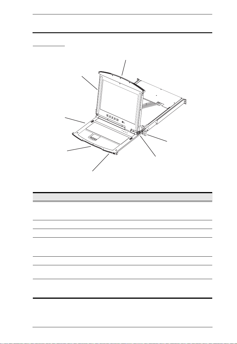
Front View
3
4
Chapter 1. Introduction
1
2
7
6
5
No. Component Description
1 Upper Handle Pull to slide the LCD module out; push to slide the module in.
2 LCD Module See LC D Module, page 7.
3 Keyboard Module See Keyboard Module, page 6.
4 Lower Handle Pull to slide the keyboard module out. See Opening the
5 Power LED Lights (blue) to indicate that the unit is receiving power.
6 LCD Release
Catch
7 Rack Mounting
Tabs
See Opening the Console, page 15, for details on sliding the
console in and out.
Console, page 15, for more details on sliding the console in
and out.
These catches (one on each side) release the LCD module
so you can slide it away.
The rack mounting tabs located at each corner of the unit
secure the chassis to a system rack. See Standard Rack
Mounting, page 12, for details.
5
KL1100 User Manual
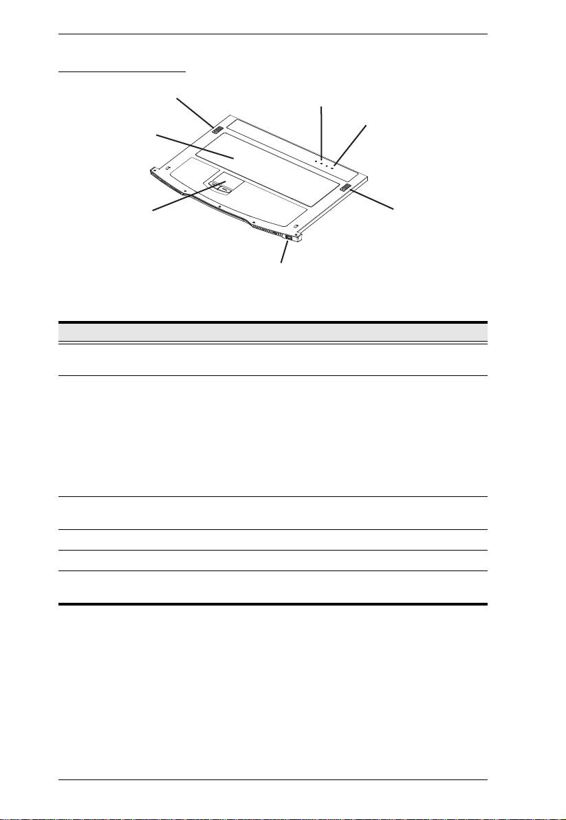
Keyboard Module
1
3
2
4
5
1
6
No. Component Description
1 Keyboard
Release Catch
2 Reset Button
These catches (one on each side) release the keyboard
module so you can slide it away.
Pressing and holding this button while powering on the unit
causes the KL1100 to revert to the original factory installed
firmware version – allowing you to recover from a failed
firmware upgrade.
Pressing and holding this button for more than three
seconds performs a system reset.
Note: The button is recessed and must be pushed with a thin
object - such as the end of a paper clip or a ballpoint pen.
3 Lock LEDs The Num Lock, Caps Lock, Scroll Lock LEDs are located
4 Keyboard Standard 105-key keyboard
5 Touch pad Standard mouse touch pad
6 External Mouse
Port
here.
This USB mouse port is provided for users who prefer to use
an external mouse.
6
Chapter 1. Introduction
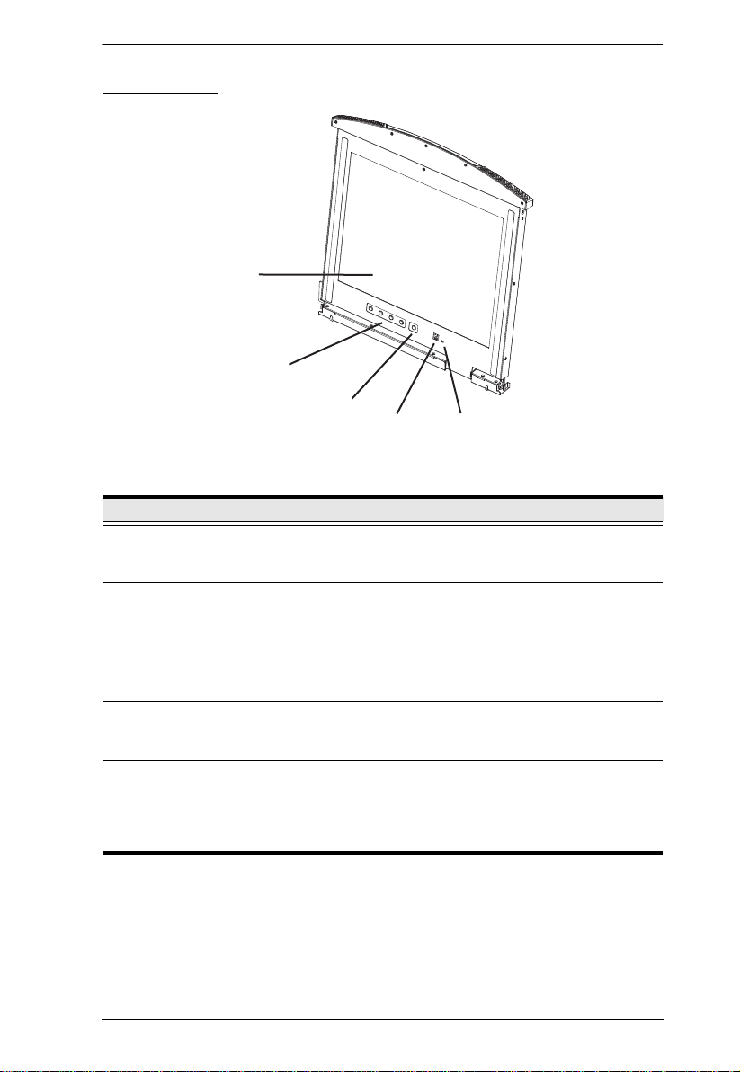
2
1
3
4
5
LCD Module
No. Component Description
1 LCD Display To access the LCD monitor , slide the LCD module out and flip
2 LCD Controls These buttons control the position and picture settings of the
3 LCD On/Off
Button
4 Firmware
Upgrade Port
5 Firmware
Upgrade Switch
up the cover. See Opening the Console, page 15, for details
on sliding the LCD module out.
LCD display. See LCD OSD Configuration, page 22, for
details.
Push this button to turn the LCD monitor on and off. The
button lights when the LCD monitor is off to indicate that only
the monitor is off – not the KVM switch itself.)
The Firmware Upgrade Cable that transfers the firmware
upgrade data from the administrator's computer to the KL1100
plugs into this RJ-11 connector.
During normal operation and while performing a firmware
upgrade, this switch should be in the NORMAL position. If a
firmware upgrade operation does not complete successfully,
this switch is used to perform a firmware upgrade recovery.
See Firmware Upgrade Recovery, page 31, for details.
7
KL1100 User Manual
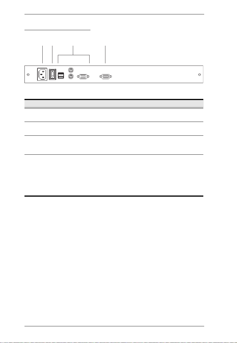
Rear View (AC Power)
2
1
No. Component Description
1 Power Socket This is a standard 3 prong AC power socket. The power cord
2 Power Switch This is a standard rocker switch that powers the KL1100 on
3 External
Console Section
4 KVM Port
Section
3
from an AC source plugs in here.
and off.
For flexibility and convenience, the KL1100 supports an
independent, external, KVM console. The external console's
keyboard, monitor, and mouse cables plug in here.
The cable linking the KL1100 to a computer or switch plugs in
here.
Note: The shape of this SPHD connector has been
specifically modified so that only KVM cables designed to
work with this console can plug in (see External Console,
page 3 for details). Do NOT attempt to use ordinary 15 pin
VGA connector cable to link this port to a computer or switch.
4
8
Chapter 1. Introduction
3
2
1
4
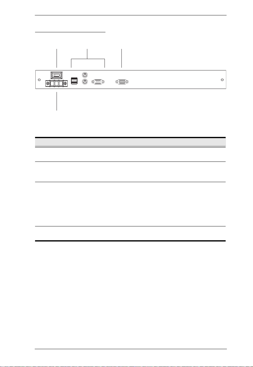
Rear View (DC Power)
No. Component Description
1 Power Switch This is a standard rocker switch that powers the KL1100 on
2 External
Console Section
3 KVM Port
Section
4 DC Terminal
Block
and off.
For flexibility and convenience, the KL1100 supports an
independent, external, KVM console. The external console's
keyboard, monitor, and mouse cables plug in here.
The cable linking the KL1100 to a computer or switch plugs in
here.
Note: The shape of this SPHD connector has been
specifically modified so that only KVM cables designed to
work with this console can plug in (see External Console,
page 3 for details). Do NOT attempt to use ordinary 15 pin
VGA connector cable to link this port to a computer or switch.
The electric leads from a DC power supply connect here.
9
 Loading...