

ATEN KH2508, KH2516 User Manual

2 Console 8/16 Port
Cat 5 High Density KVM Switch
KH2508 / KH2516
User Manual
www.aten.com
KH2508 / KH2516 User Manual
FCC, CE Information
FEDERAL COMMUNICATIONS COMMISSION INTERFERENCE
STATEMENT: This equipment has been tested and found to comply with the
limits for a Class A digital device, pursuant to Part 15 of the FCC Rules. These
limits are designed to provide reasonable protection against harmful
interference when the equipment is operated in a commercial environment.
This equipment generates, uses, and can radiate radio frequency energy and, if
not installed and used in accordance with the instruction manual, may cause
harmful interference to radio communications. Operation of this equipment in
a residential area is likely to cause harmful interference in which case the user
will be required to correct the interference at his own expense.
FCC Caution: Any changes or modifications not expressly approved by the
party responsible for compliance could void the user's authority to operate this
equipment.
CE Warning: This is a class A product. In a domestic environment this product
may cause radio interference in which case the user may be required to take
adequate measures.
RoHS
This product is RoHS compliant.
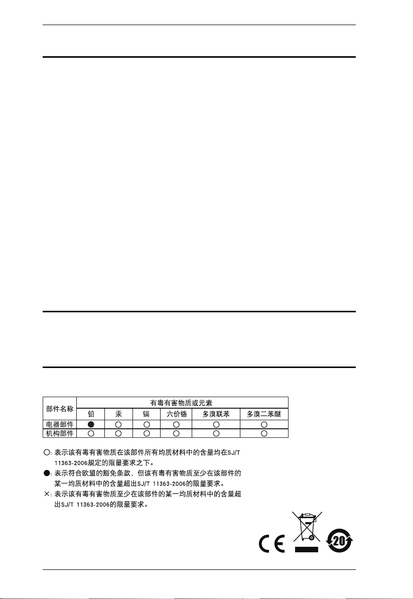
SJ/T 11364-2006
The following contains information that relates to China.
ii

KH2508 / KH2516 User Manual
User Information
Online Registration
Be sure to register your product at our online support center:
International http://eservice.aten.com
Telephone Support
For telephone support, call this number:
International 886-2-8692-6959
China 86-10-5255-0110
Japan 81-3-5615-5811
Korea 82-2-467-6789
North America 1-888-999-ATEN ext 4988
United Kingdom 44-8-4481-58923
User Notice
All information, documentation, and specifications contained in this manual
are subject to change without prior notification by the manufacturer. The
manufacturer makes no representations or warranties, either expressed or
implied, with respect to the contents hereof and specifically disclaims any
warranties as to merchantability or fitness for any particular purpose. Any of
the manufacturer's software described in this manual is sold or licensed as is.
Should the programs prove defective following their purchase, the buyer (and
not the manufacturer, its distributor, or its dealer), assumes the entire cost of all
necessary servicing, repair and any incidental or consequential damages
resulting from any defect in the software.
The manufacturer of this system is not responsible for any radio and/or TV
interference caused by unauthorized modifications to this device. It is the
responsibility of the user to correct such interference.
The manufacturer is not responsible for any damage incurred in the operation
of this system if the correct operational voltage setting was not selected prior
to operation. PLEASE VERIFY THAT THE VOLTAGE SETTING IS
CORRECT BEFORE USE.
iii

KH2508 / KH2516 User Manual
Copyright © 2014 ATEN® International Co., Ltd.
Manual Part No. PAPE-0292-AX1G
F/W Version: 1.1.101
Manual Date: 2014-02-27
Altusen and the Altusen logo are registered trademarks of ATEN International Co., Ltd. All rights reserved.
All other brand names and trademarks are the registered property of their respective owners.
Package Contents
The KH2508 / KH2516 package consists of:
1 KH2508 / KH2516 Cat 5 KVM Switch
1Power Cord
1 Grounding Wire
1 Firmware Upgrade Cable
1 Rack Mount Kit
1 Foot Pad Set (4 pcs.)
1 User Manual*
1 Quick Start Guide
Check to make sure that all of the components are present and in good order.
If anything is missing, or was damaged in shipping, contact your dealer.
Read this manual thoroughly and follow the installation and operation
procedures carefully to prevent any damage to the switch or to any other
devices on the KH2508 / KH2516 installation.
* Features may have been added to the KH2508 / KH2516 since this manual
was published. Please visit our website to download the most up to date
version of the manual.
iv

KH2508 / KH2516 User Manual
Contents
FCC, CE Information. . . . . . . . . . . . . . . . . . . . . . . . . . . . . . . . . . . . . . . . . . ii
SJ/T 11364-2006. . . . . . . . . . . . . . . . . . . . . . . . . . . . . . . . . . . . . . . . . . . . . ii
User Information . . . . . . . . . . . . . . . . . . . . . . . . . . . . . . . . . . . . . . . . . . . . .iii
Online Registration . . . . . . . . . . . . . . . . . . . . . . . . . . . . . . . . . . . . . . . .iii
Telephone Support . . . . . . . . . . . . . . . . . . . . . . . . . . . . . . . . . . . . . . . .iii
User Notice . . . . . . . . . . . . . . . . . . . . . . . . . . . . . . . . . . . . . . . . . . . . . .iii
Package Contents. . . . . . . . . . . . . . . . . . . . . . . . . . . . . . . . . . . . . . . . . . . iv
About This Manual . . . . . . . . . . . . . . . . . . . . . . . . . . . . . . . . . . . . . . . . . .viii
Overview . . . . . . . . . . . . . . . . . . . . . . . . . . . . . . . . . . . . . . . . . . . . . . .viii
Conventions . . . . . . . . . . . . . . . . . . . . . . . . . . . . . . . . . . . . . . . . . . . . ix
Product Information. . . . . . . . . . . . . . . . . . . . . . . . . . . . . . . . . . . . . . . . . . ix
Chapter 1.
Introduction
Overview . . . . . . . . . . . . . . . . . . . . . . . . . . . . . . . . . . . . . . . . . . . . . . . . . . .1
Features . . . . . . . . . . . . . . . . . . . . . . . . . . . . . . . . . . . . . . . . . . . . . . . . . . .3
Requirements . . . . . . . . . . . . . . . . . . . . . . . . . . . . . . . . . . . . . . . . . . . . . . . 4
Consoles . . . . . . . . . . . . . . . . . . . . . . . . . . . . . . . . . . . . . . . . . . . . . . . . 4
Computers. . . . . . . . . . . . . . . . . . . . . . . . . . . . . . . . . . . . . . . . . . . . . . .4
KVM Adapter Cables. . . . . . . . . . . . . . . . . . . . . . . . . . . . . . . . . . . . . . . 4
Other Cables . . . . . . . . . . . . . . . . . . . . . . . . . . . . . . . . . . . . . . . . . . . . .5
Operating Systems . . . . . . . . . . . . . . . . . . . . . . . . . . . . . . . . . . . . . . . . 5
Components . . . . . . . . . . . . . . . . . . . . . . . . . . . . . . . . . . . . . . . . . . . . . . . . 6
Front View . . . . . . . . . . . . . . . . . . . . . . . . . . . . . . . . . . . . . . . . . . . . . . .6
Rear View . . . . . . . . . . . . . . . . . . . . . . . . . . . . . . . . . . . . . . . . . . . . . . .8
Local Console Connection . . . . . . . . . . . . . . . . . . . . . . . . . . . . . . . . . . 9
Chapter 2.
Hardware Setup
Overview . . . . . . . . . . . . . . . . . . . . . . . . . . . . . . . . . . . . . . . . . . . . . . . . . .11
Before you Begin. . . . . . . . . . . . . . . . . . . . . . . . . . . . . . . . . . . . . . . . . . . .11
Stacking and Rack Mounting . . . . . . . . . . . . . . . . . . . . . . . . . . . . . . . . . .12
Stacking. . . . . . . . . . . . . . . . . . . . . . . . . . . . . . . . . . . . . . . . . . . . . . . .12
Rack Mounting – Front . . . . . . . . . . . . . . . . . . . . . . . . . . . . . . . . . . . .13
Rack Mounting – Rear. . . . . . . . . . . . . . . . . . . . . . . . . . . . . . . . . . . . .15
Grounding . . . . . . . . . . . . . . . . . . . . . . . . . . . . . . . . . . . . . . . . . . . . . . . . .16
Single Level Installation . . . . . . . . . . . . . . . . . . . . . . . . . . . . . . . . . . . . . . 17
KVM Adapter Cable Installation Diagrams . . . . . . . . . . . . . . . . . . . . .19
Cascaded Installations . . . . . . . . . . . . . . . . . . . . . . . . . . . . . . . . . . . . . . . 20
Cascading KH2508 / KH2516 Cat 5 KVM Switches . . . . . . . . . . .21
v

KH2508 / KH2516 User Manual
Chapter 3.
Basic Operation
Hot Plugging . . . . . . . . . . . . . . . . . . . . . . . . . . . . . . . . . . . . . . . . . . . . . . . 25
Changing Cascaded Switch Positions . . . . . . . . . . . . . . . . . . . . . . . . 25
Hot Plugging Console Ports . . . . . . . . . . . . . . . . . . . . . . . . . . . . . . . . 25
Powering Off and Restarting. . . . . . . . . . . . . . . . . . . . . . . . . . . . . . . . . . . 25
Port Selection . . . . . . . . . . . . . . . . . . . . . . . . . . . . . . . . . . . . . . . . . . . . . . 25
Chapter 4.
OSD Operation
OSD Overview . . . . . . . . . . . . . . . . . . . . . . . . . . . . . . . . . . . . . . . . . . . . . 27
The Main Page . . . . . . . . . . . . . . . . . . . . . . . . . . . . . . . . . . . . . . . . . . . . . 29
Quick View Ports. . . . . . . . . . . . . . . . . . . . . . . . . . . . . . . . . . . . . . . . . 30
The List Function. . . . . . . . . . . . . . . . . . . . . . . . . . . . . . . . . . . . . . . . . 31
Port Names . . . . . . . . . . . . . . . . . . . . . . . . . . . . . . . . . . . . . . . . . . . . . 33
Port Operation . . . . . . . . . . . . . . . . . . . . . . . . . . . . . . . . . . . . . . . . . . . . . 36
The OSD Toolbar . . . . . . . . . . . . . . . . . . . . . . . . . . . . . . . . . . . . . . . . 36
The Toolbar Icons . . . . . . . . . . . . . . . . . . . . . . . . . . . . . . . . . . . . . . . . 37
Recalling the OSD. . . . . . . . . . . . . . . . . . . . . . . . . . . . . . . . . . . . . . . . 38
OSD Hotkey Summary Table . . . . . . . . . . . . . . . . . . . . . . . . . . . . . . . 38
Port Operation Hotkey Overview. . . . . . . . . . . . . . . . . . . . . . . . . . . . . 38
Auto Scanning. . . . . . . . . . . . . . . . . . . . . . . . . . . . . . . . . . . . . . . . . . . 39
Setting the Scan Interval . . . . . . . . . . . . . . . . . . . . . . . . . . . . . . . . 39
Invoking Auto Scan . . . . . . . . . . . . . . . . . . . . . . . . . . . . . . . . . . . . 39
Pausing Auto Scan . . . . . . . . . . . . . . . . . . . . . . . . . . . . . . . . . . . . 39
Exiting Auto Scan Mode . . . . . . . . . . . . . . . . . . . . . . . . . . . . . . . . 39
Skip Mode . . . . . . . . . . . . . . . . . . . . . . . . . . . . . . . . . . . . . . . . . . . . . . 40
The Configuration Page . . . . . . . . . . . . . . . . . . . . . . . . . . . . . . . . . . . . . . 40
The Administration Page . . . . . . . . . . . . . . . . . . . . . . . . . . . . . . . . . . . . . 42
General . . . . . . . . . . . . . . . . . . . . . . . . . . . . . . . . . . . . . . . . . . . . . . . . 42
User Management . . . . . . . . . . . . . . . . . . . . . . . . . . . . . . . . . . . . . . . . . . 43
Port Access . . . . . . . . . . . . . . . . . . . . . . . . . . . . . . . . . . . . . . . . . . . . . 45
System . . . . . . . . . . . . . . . . . . . . . . . . . . . . . . . . . . . . . . . . . . . . . . . . . . . 46
Configuration. . . . . . . . . . . . . . . . . . . . . . . . . . . . . . . . . . . . . . . . . . . . 46
Adapter Cable . . . . . . . . . . . . . . . . . . . . . . . . . . . . . . . . . . . . . . . . . . . 47
Upgrade Failed . . . . . . . . . . . . . . . . . . . . . . . . . . . . . . . . . . . . . . . 51
Attributes . . . . . . . . . . . . . . . . . . . . . . . . . . . . . . . . . . . . . . . . . . . . 52
Changing Attributes . . . . . . . . . . . . . . . . . . . . . . . . . . . . . . . . . . . . 53
Operation Mode Attributes . . . . . . . . . . . . . . . . . . . . . . . . . . . . . . 54
Miscellaneous . . . . . . . . . . . . . . . . . . . . . . . . . . . . . . . . . . . . . . . . . . . 54
Date/Time . . . . . . . . . . . . . . . . . . . . . . . . . . . . . . . . . . . . . . . . . . . . . . . . . 55
The Log Page . . . . . . . . . . . . . . . . . . . . . . . . . . . . . . . . . . . . . . . . . . . . . . 56
Chapter 5.
The Firmware Upgrade Utility
Introduction . . . . . . . . . . . . . . . . . . . . . . . . . . . . . . . . . . . . . . . . . . . . . . . . 57
vi

KH2508 / KH2516 User Manual
Downloading the Firmware Upgrade Package . . . . . . . . . . . . . . . . . . 57
Preparing to Upgrade the Firmware . . . . . . . . . . . . . . . . . . . . . . . . . .58
Performing the Upgrade . . . . . . . . . . . . . . . . . . . . . . . . . . . . . . . . . . . . . . 59
Upgrade Successful . . . . . . . . . . . . . . . . . . . . . . . . . . . . . . . . . . . . . . 63
Stopping the Firmware Upgrade . . . . . . . . . . . . . . . . . . . . . . . . . . . . . . . .64
Upgrading Adapter Cables . . . . . . . . . . . . . . . . . . . . . . . . . . . . . . . . . . . . 64
Upgrade Failed . . . . . . . . . . . . . . . . . . . . . . . . . . . . . . . . . . . . . . . . . . . . .65
Firmware Upgrade Recovery . . . . . . . . . . . . . . . . . . . . . . . . . . . . . . . . . . 65
Chapter 6.
Keyboard Emulation
Mac Keyboard . . . . . . . . . . . . . . . . . . . . . . . . . . . . . . . . . . . . . . . . . . . . . .67
Sun Keyboard . . . . . . . . . . . . . . . . . . . . . . . . . . . . . . . . . . . . . . . . . . . . . .68
Appendix
Safety Instructions. . . . . . . . . . . . . . . . . . . . . . . . . . . . . . . . . . . . . . . . . . .69
General . . . . . . . . . . . . . . . . . . . . . . . . . . . . . . . . . . . . . . . . . . . . . . . .69
Rack Mounting . . . . . . . . . . . . . . . . . . . . . . . . . . . . . . . . . . . . . . . . . .71
Consignes de sécurité. . . . . . . . . . . . . . . . . . . . . . . . . . . . . . . . . . . . . . . .72
Général . . . . . . . . . . . . . . . . . . . . . . . . . . . . . . . . . . . . . . . . . . . . . . . .72
Montage sur bâti . . . . . . . . . . . . . . . . . . . . . . . . . . . . . . . . . . . . . . . . .75
Technical Support . . . . . . . . . . . . . . . . . . . . . . . . . . . . . . . . . . . . . . . . . . .76
International. . . . . . . . . . . . . . . . . . . . . . . . . . . . . . . . . . . . . . . . . . . . . 76
North America . . . . . . . . . . . . . . . . . . . . . . . . . . . . . . . . . . . . . . . . . . .76
Specifications . . . . . . . . . . . . . . . . . . . . . . . . . . . . . . . . . . . . . . . . . . . . . .77
OSD Factory Default Settings. . . . . . . . . . . . . . . . . . . . . . . . . . . . . . . . . .78
Troubleshooting . . . . . . . . . . . . . . . . . . . . . . . . . . . . . . . . . . . . . . . . . . . .79
Overview . . . . . . . . . . . . . . . . . . . . . . . . . . . . . . . . . . . . . . . . . . . . . . .79
General . . . . . . . . . . . . . . . . . . . . . . . . . . . . . . . . . . . . . . . . . . . . . . . .79
Sun Systems . . . . . . . . . . . . . . . . . . . . . . . . . . . . . . . . . . . . . . . . . . . .81
Restoring Original Factory Default Settings . . . . . . . . . . . . . . . . . . . . . . . 82
Entering the ok Prompt (Sun Solaris) . . . . . . . . . . . . . . . . . . . . . . . . . . . . 83
Supported KVM Switches . . . . . . . . . . . . . . . . . . . . . . . . . . . . . . . . . . . . .83
Limited Warranty . . . . . . . . . . . . . . . . . . . . . . . . . . . . . . . . . . . . . . . . . . . . 84
vii

KH2508 / KH2516 User Manual
About This Manual
This user manual is provided to help you get the most from your KH2508 /
KH2516 system. It covers all aspects of installation, configuration and
operation. An overview of the information found in the manual is provided
below.
Overview
Chapter 1, Introduction, introduces you to the KH2508 / KH2516 system.
Its purpose, features, and benefits are presented, and its front and back panel
components are described.
Chapter 2, Hardware Setup, provides step-by-step instructions for setting
up your installation, and explains some basic operating procedures.
Chapter 3, Basic Operation, explains the fundamental concepts involved
in operating the KH2508 / KH2516.
Chapter 4, OSD Operation, provides detailed information for configuring
and controlling your installation using the KH2508 / KH2516’s intuitive,
mouse-driven on-screen display (OSD) menus.
Chapter 5, The Firmware Upgrade Utility, explains how to upgrade the
KH2508 / KH2516's firmware with the latest available versions.
Chapter 6, Keyboard Emulation, lists the keys for a PC-compatible
keyboard to emulate the functions of the Mac and Sun keyboards.
An Appendix at the end of the manual provides technical and
troubleshooting information.
viii

Conventions
This manual uses the following conventions:
Monospaced Indicates text that you should key in.
[ ] Indicates keys you should press. For example, [Enter] means
to press the Enter key. If keys need to be chorded, they appear
together in the same bracket with a plus sign between them:
[Ctrl+Alt].
1. Numbered lists represent procedures with sequential steps.
♦ Bullet lists provide information, but do not involve sequential
steps.
→ Indicates selecting the option (on a menu or dialog box, for
example), that comes next. For example, Start
to open the Start menu, and then select Run.
Indicates critical information.
Product Information
KH2508 / KH2516 User Manual
→ Run means
For information about all ATEN products and how they can help you connect
without limits, visit ATEN on the Web or contact an ATEN Authorized
Reseller. Visit ATEN on the Web for a list of locations and telephone numbers:
International http://www.aten.com
North America http://www.aten-usa.com
ix

KH2508 / KH2516 User Manual
This Page Intentionally Left Blank
x

Chapter 1
Introduction
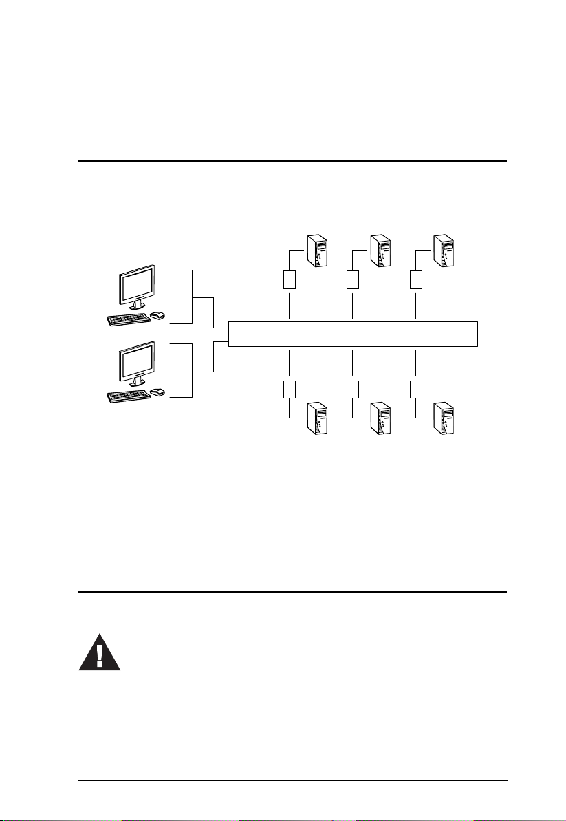
Overview
The KH2508 / KH2516 Cat 5 High Density KVM Switches give IT
administrators advanced control of multiple computers. Operators working at
up to two keyboard, monitor, and mouse (KVM) consoles can independently
and simultaneously take direct control of up to 8 or 16 computers in a singlelevel installation, or up to 512 or 4096 KVM ports in a full three-level cascaded
switch installation. Cascading is achieved via dedicated RJ-45 cascade ports
and Cat 5e cabling.
The two KVM consoles belonging to the first-level KH2508 / KH2516 are able
to access all the computers on the installation – those that are directly
connected to the switch, as well as those that are cascaded. Where applicable,
one KVM console belonging to each cascaded KH2508 / KH2516 can access
the computers on the same, or lower level.
The KH2508 / KH2516 feature RJ-45 connectors and Cat 5e cable to link to
the computers. 1280 x 1024 @ 75Hz video signals can travel up to
40 m (130 feet), eliminating the need for KVM extenders. Utilizing PS/2 and
USB KVM adapter cables for the final linkup, the KH2508 / KH2516 permits
any combination of PCs, Macs, Sun computers, and serial devices to coexist on
the installation. Additionally, the use of RJ-45 connectors saves precious IT
real estate by allowing 8 or 16 KVM ports to reside in a single 1U housing.
Access to any computer connected to the installation is easily accomplished by
means of mouse-driven on-screen display (OSD) menus. A convenient Auto
Scan feature also permits automatic scanning and monitoring of the activities
of computers running on the installation one-by-one.
Setup is fast and easy – plugging cables into their appropriate ports is all that
is entailed. Because the KH2508 / KH2516 intercepts keyboard and mouse
input directly, there is no software to configure, and no need to get involved in
complex installation routines, or be concerned with incompatibility problems.
Your KH2508 / KH2516 investment is protected by a Firmware Upgrade
Utility. You can stay current with the latest improvements in functionality by
using the Firmware Upgrade Utility to upgrade your installation. Check our
website frequently to download the latest updates to the KH2508 / KH2516
Firmware Upgrade Utility.
1

KH2508 / KH2516 User Manual
There is no better way to save time and money than with a KH2508 / KH2516
installation. By allowing two consoles to manage up to 4096 computers, a
KH2508 / KH2516 installation: (1) eliminates the expense of having to
purchase a separate keyboard, monitor, and mouse for each; (2) saves all the
space those extra components would take up; (3) saves on energy costs; and (4)
eliminates the inconvenience and wasted effort involved in constantly moving
from one computer to another.
With their advanced security features, the KH2508 / KH2516 Cat 5 High
Density KVM Switches provide the fastest, most reliable, most cost effective
way to access and manage multiple computer installations.
2

Chapter 1. Introduction
Features
Two KVM consoles independently and simultaneously control up to 8 or
16 directly connected computers
Cascade up to 3 levels of KH2508 or KH2516 switches to support up to
512 or 4096 computers
Superior video resolution – 1280 x 1024 @ 75 Hz up to 40 m; 1600 x 1200
@ 60 Hz up to 30 m
Multiplatform support: PC, Mac, Sun, and serial
Backup and restore configuration settings to an external flash drive to
simplify installation on multiple switches, or for disaster recovery
No software to install – convenient computer selection via graphical
on-screen display (OSD) menus
Supports two-level user access control (administrator and user)
Supports up to 96 user accounts
Configure port access rights for users on a port-by-port basis
Diversified port operation mode enables flexible computer management –
Occupy, Exclusive and Share modes
OSD port list automatically expands when stations are added
Port names are automatically reconfigured when the station/computer
sequence is changed
OSD screen automatically adjusts to resolution changes
Auto Scan mode enables continuous monitoring of user-selected computers
User activity log support
Console conversion – any type of KVM console can control any type of
computer; mixed combinations (PS/2 & USB) supported on both the KVM
console and computer sides
USB / PS/2 keyboard and mouse emulation – computers boot even when
the KVM console focus is elsewhere
Hot pluggable – add or remove components without having to power off
the KVM switch
Free lifetime firmware upgrades
Effortlessly upgrade an entire installation – automatically upgrade all
cascaded switches and adapter cables directly from the root station
Compact design – rack mounts in only 1U of rack space
1
1. Occupy, Exclusive and Share modes supported on the first level switch only. Cascaded
switches operate under Cascade mode. See page 46.
3
KH2508 / KH2516 User Manual
Requirements
Consoles
The following hardware components are required for each KVM console:
A VGA, SVGA, or multisync monitor capable of displaying the highest
resolution provided by any computer in the installation
Keyboard and mouse (PS/2 or USB)
Computers
The following hardware components are required for each computer:
A VGA, SVGA, or multisync video graphics card with an HDB-15 port;
or, for Sun legacy systems, a Sun 13W3 video port
PS/2 mouse and keyboard ports (6-pin Mini-DIN), or at least one USB port;
or, for Sun legacy systems, a Sun style keyboard port (8-pin Mini-DIN)
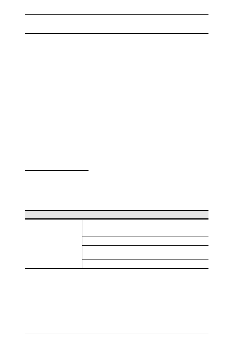
KVM Adapter Cables
KVM adapter cables together with Cat 5e cabling connect multiplatform
computers (PS/2, USB, Sun, Mac, and serial devices) to the KH2508 /
KH2516. The KVM adapter cables currently available are listed in the table
below. Contact your dealer for details.
Function Model Number
KVM adapter cables For PS/2 computers KA9520
For USB computers KA9570
For Sun legacy systems KA9130
For Sun USB systems KA9131
For serial devices KA9140
4
KA9170
Chapter 1. Introduction
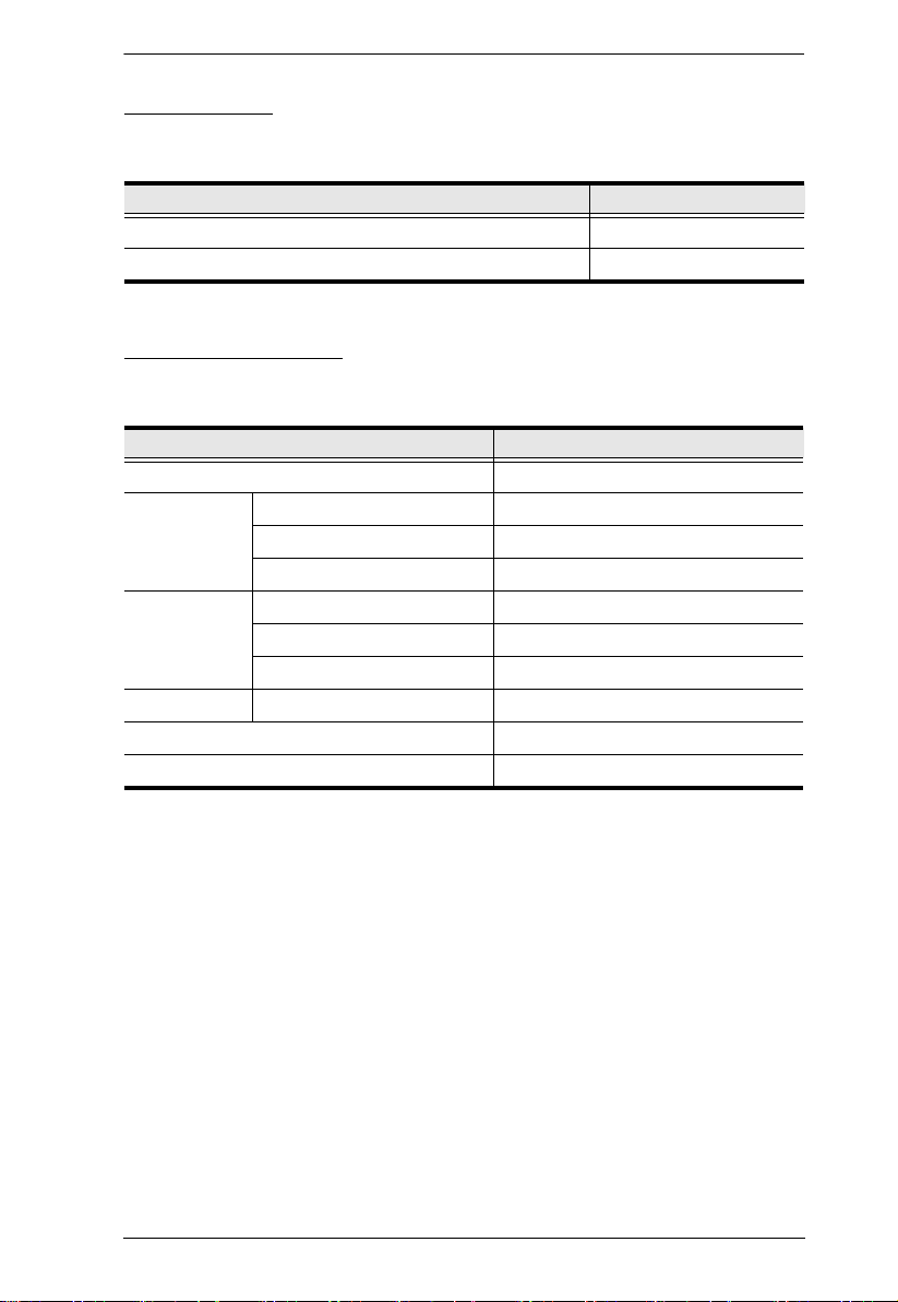
Other Cables
The following cables are also required for use with the KH2508 / KH2516.
Function Typ e
KVM adapter cable to KH2508 / KH2516 (see page 19) Cat 5e cable
Cascading (see page 20) Cat 5e cable
Operating Systems
Supported operating systems are shown in the table, below.
OS Ver sio n
Windows ME, NT, 2000 and higher
Linux RedHat 6.0 and higher
SuSE 8.2 and higher
Mandriva (Mandrake) 9.0 and higher
UNIX AIX 4.3 and higher
FreeBSD 3.51 and higher
Sun Solaris 8 and higher
Novell Netware 5.0 and higher
Mac 8.6 and higher
OS/2 Warp and higher
5
KH2508 / KH2516 User Manual
6
1
7
2 3
5
4
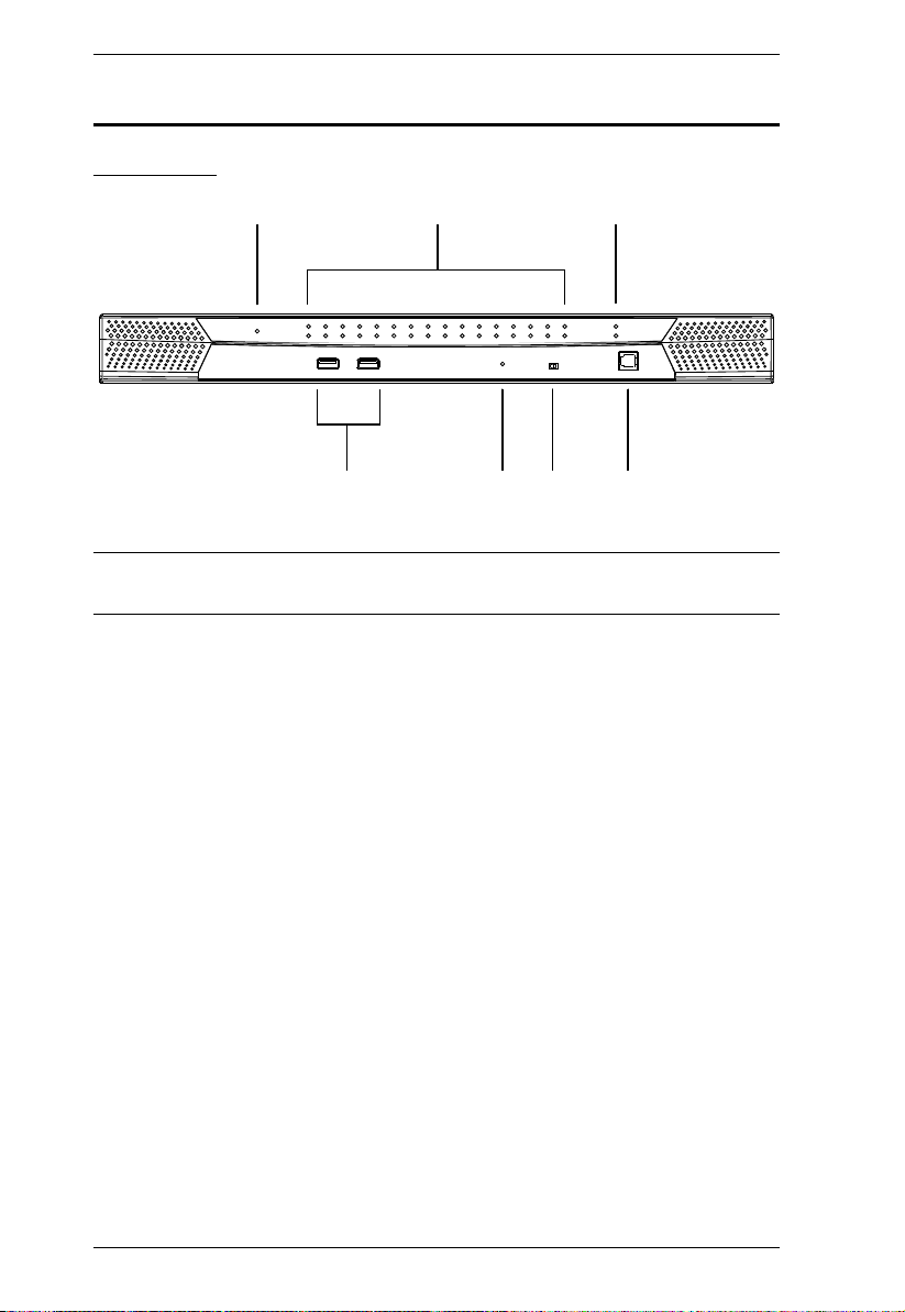
Components
Front View
Note: The KH2516 is pictured above. The KH2508 front panel is the same as
that of the KH2516, except that it has 8 KVM port LEDs instead of 16.
6

Chapter 1. Introduction
No. Component Description
1 Power LED Lights (blue) to indicate that the unit is receiving power.
2 Port LEDs
A green LED indicates that a computer is connected
to the corresponding port.
A flashing green LED indicates a connection to a
cascaded child KVM switch.
A red LED indicates that the computer connected to
the corresponding port has focus.
A flashing red LED indicates that the computer
connected to the corresponding cascaded port
has focus.
3 Cascade Port LEDs A flashing green LED indicates a connection between
4 USB Ports Connect USB flash drives to these ports to backup and
5 Reset Button Pressing in this button performs a system reset. When
6 Firmware Upgrade
Recovery Switch
7 Firmware Upgrade
Port
cascaded parent and child KVM switches.
restore configuration settings for consoles 1 and 2.
See Configuration, page 46.
the system is reset, the KH2508 / KH2516 beeps, and
then the KVM port LEDs flash in succession until the
reset is completed. After the reset is completed you can
login again.
Note: This button is semi-recessed and must be
pushed with a small object, such as the end of a paper
clip or a ballpoint pen.
During normal operation and while performing a
firmware upgrade, this switch should be in the
NORMAL position. If a firmware upgrade operation
does not complete successfully, this switch is used to
perform a firmware upgrade recovery. See Firmware
Upgrade Recovery, page 65, for details.
The firmware upgrade cable that transfers the firmware
upgrade data from the administrator's computer to the
KH2508 / KH2516, plugs into this RJ-11 connector.
7
KH2508 / KH2516 User Manual
1
4
65
2
3
7
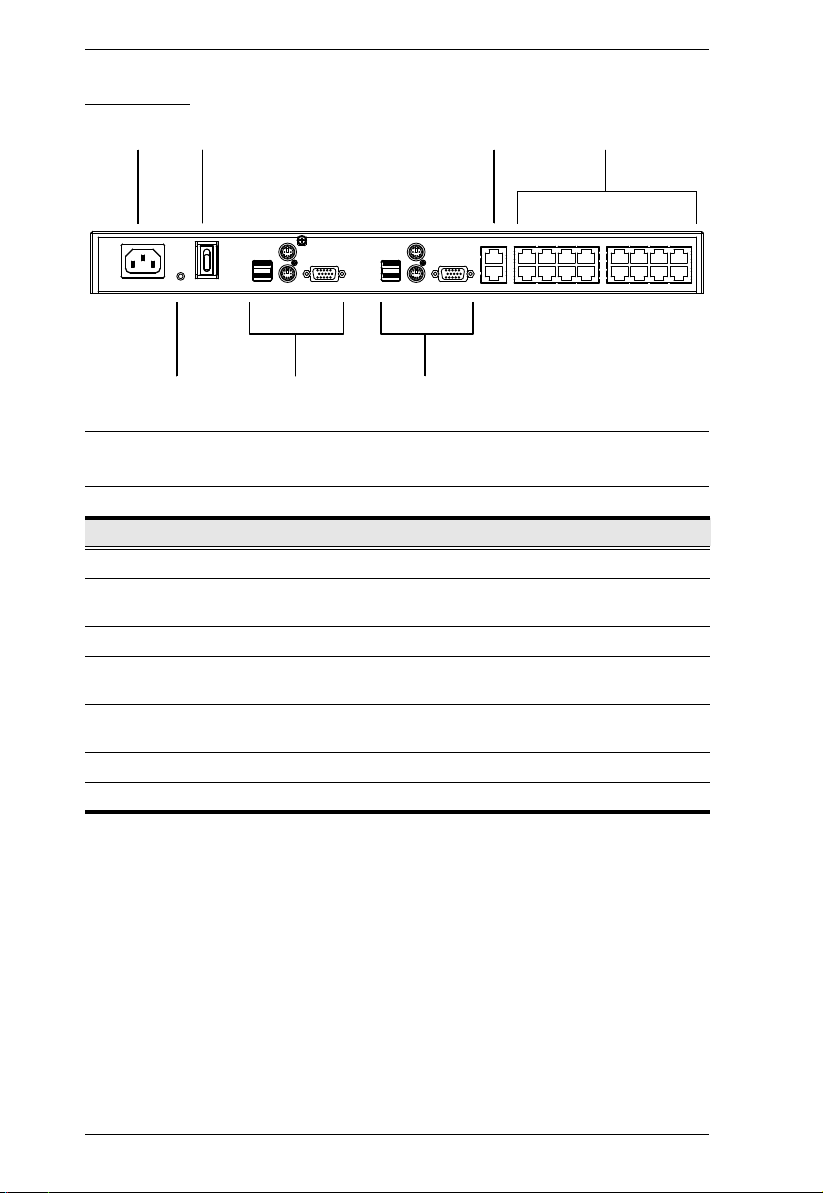
Rear View
Note: The KH2516 is pictured above. The KH2508 rear panel is the same as
that of the KH2516, except that it has 8 KVM ports instead of 16.
No. Component Description
1 Power Socket The power cord to the AC source plugs in here.
2 Power Switch This is a standard rocker switch that powers the
3 Cascade Ports When cascading units, the Cat 5e cables plug in here.
4 KVM Port Section The Cat 5e cables that link the KVM adapter cables to
5 Grounding Terminal The grounding wire used to ground the unit attaches
6 Console 1 Port Section See Local Console Connection, page 9 for details.
7 Console 2 Port Section See Local Console Connection, page 9 for details.
KH2508 / KH2516 on and off.
the KH2508 / KH2516 plug in here.
here.
8
Chapter 1. Introduction
2
1
3
4 5
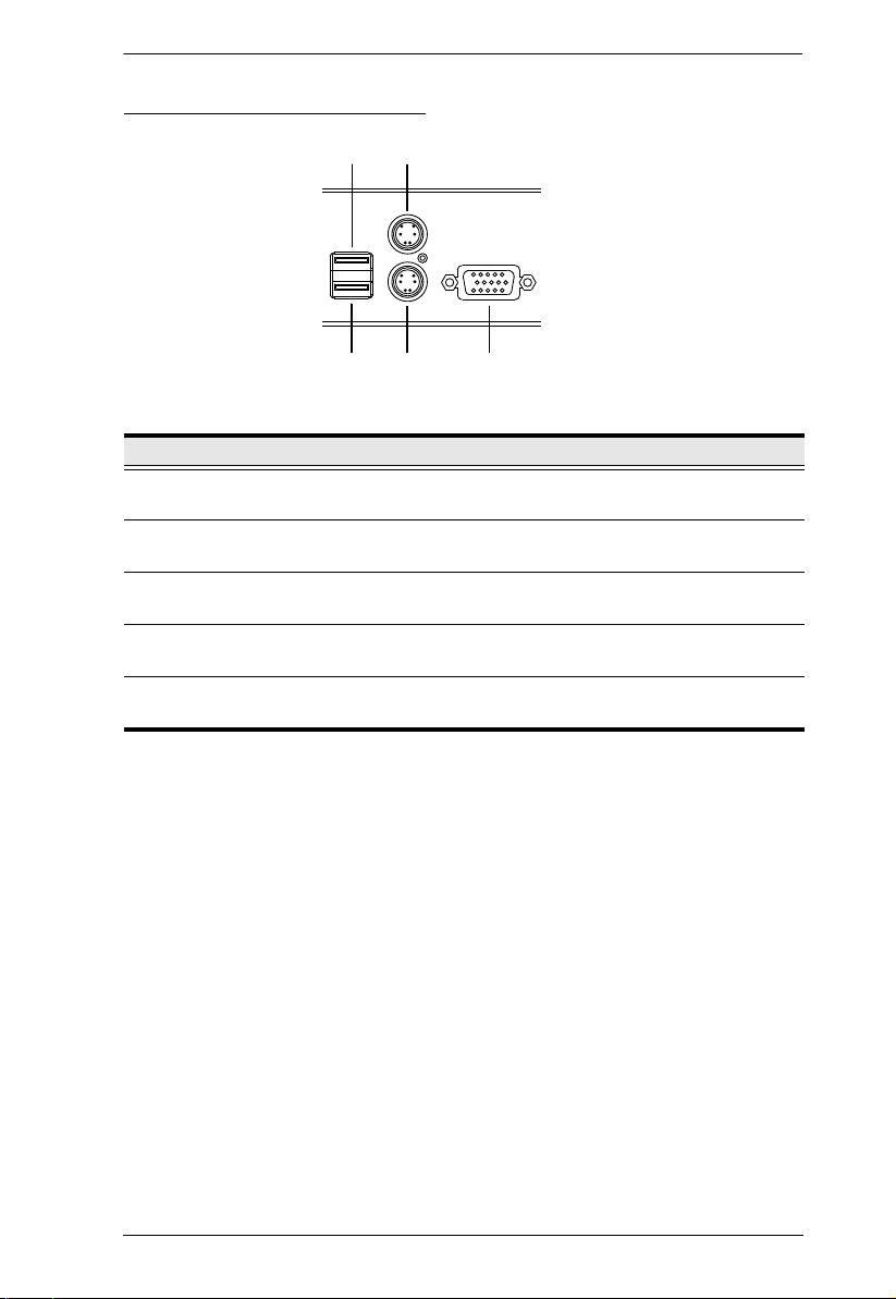
Local Console Connection
No. Component Description
1 USB Mouse Port Use the USB mouse port to connect a USB
2 USB Keyboard Port Use the USB keyboard port to connect a USB
3 PS/2 Mouse Port Use the PS/2 mouse port to connect a PS/2
4 PS/2 Keyboard Port Use the PS/2 keyboard port to connect a PS/2
5 HDB-15 Video Port Use the HDB-15 video port to connect a monitor
mouse to the console.
keyboard to the console.
mouse to the console.
keyboard to the console.
to the console.
9

KH2508 / KH2516 User Manual
This Page Intentionally Left Blank
10
Chapter 2
1. Important safety information regarding the placement of this
device is provided on page 69. Please review it before proceeding.
2. Make sure that the power to any device that you connect to the
installation has been turned off. You m
ust unplug the power cords
of any computers that have the Keyboard Power On function.
Hardware Setup
Overview
For convenience and flexibility that allows mixing the PS/2, USB and serial
interfaces, the KH2508 / KH2516's design utilizes KVM adapter cables that
serve as intermediaries between the KVM switch and the connected devices:
KA9130
KH2508 / KH2516
KA9170
A separate KVM adapter cable is required for each computer or device
connection. The KVM adapter cables are listed in the KVM Adapter Cables
section on page 4. Consult your dealer to find out which KVM adapter cables
best fit your needs.
KA9131
KA9520 KA9570
KA9140
Before you Begin
11
KH2508 / KH2516 User Manual
Stacking and Rack Mounting
The KH2508 / KH2516 can be stacked on a desktop or rack mounted in 1U of
rack space. The procedures for each method are described in the following
sections.
Note: 1. Allow at least 5.1 cm on each side for adequate ventilation and
12.7 cm at the rear for power cord and cable clearance.
2. The standard rack mounting kit does not include screws or cage nuts.
If you need additional screws or cage nuts, contact your rack dealer.
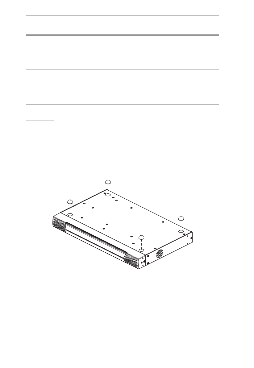
Stacking
The KH2508 / KH2516 can be placed on any level surface that can safely
support its weight and the weight of the attached cables. Ensure that the surface
is clean and free of materials that can block the exhaust vents or otherwise
interfere with normal operation of the switch. A foot pad set is included with
the unit. Peel the protective backing off of the foot pads, and then affix them to
the bottom panel of the KH2508 / KH2516 near the corners, as shown in the
diagram below.
12
Chapter 2. Hardware Setup
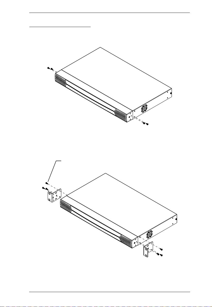
Phillips Hex Head M3 x 8
Rack Mounting – Front
1. Remove 2 screws each from the left and right sides near the front of the
switch (4 screws total).
2. Use the M3 x 8 Phillips hex head screws supplied with the rack mounting
kit to screw the rack mounting brackets into the sides at the front of the
unit.
(Continues on next page.)
13
KH2508 / KH2516 User Manual
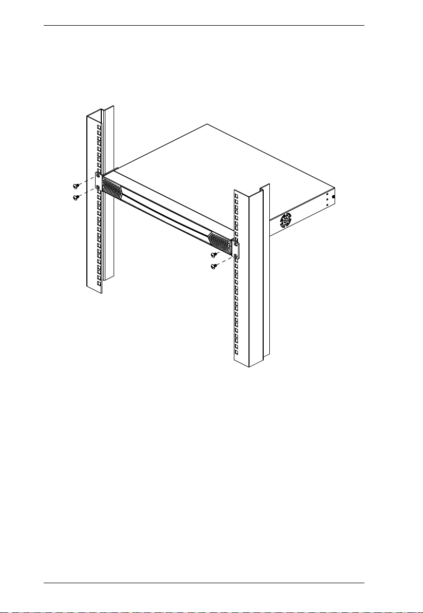
(Continued from previous page.)
3. Place the KVM switch in the rack. Position it so that the holes in the
mounting brackets line up with those in the rack. Secure the mounting
brackets to the front of the rack.
14
Chapter 2. Hardware Setup
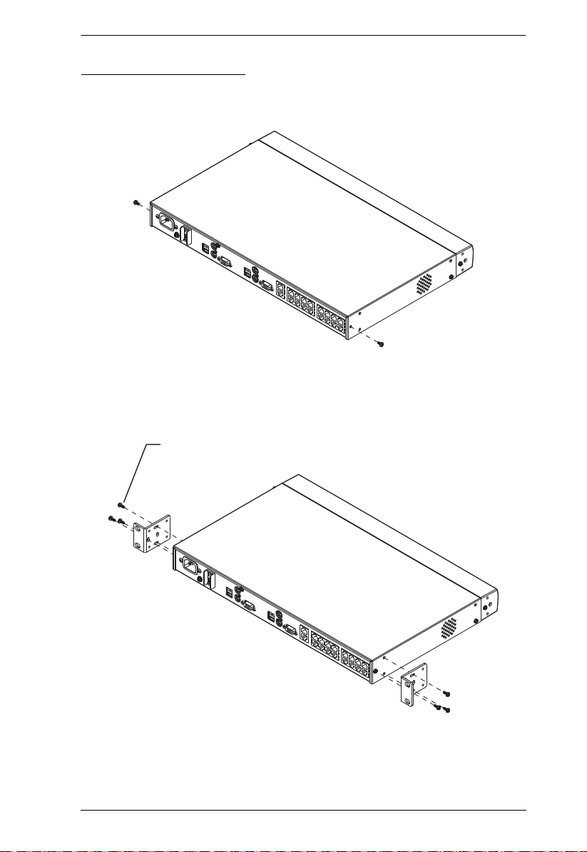
Phillips Hex Head
M3 x 8
Rack Mounting – Rear
1. Remove 1 screws each from the left and right sides near the rear of the
switch (2 screws total).
2. Use the M3 x 8 Phillips head hex screws supplied with the rack mounting
kit to screw the rack mounting brackets into the sides at the rear of the
unit.
(Continues on next page.)
15
KH2508 / KH2516 User Manual
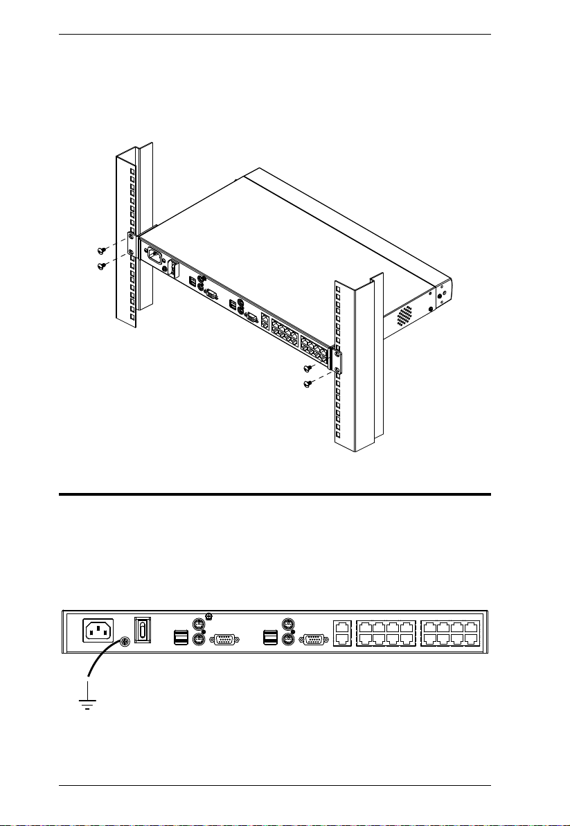
(Continued from previous page.)
3. Place the KVM switch in the rack. Position it so that the holes in the
mounting brackets line up with those in the rack. Secure the mounting
brackets to the rear of the rack.
Grounding
To prevent damage to your installation it is important that all devices are
properly grounded.
Use a grounding wire to ground the KH2508 / KH2516 by connecting one end
of the wire to the grounding terminal, and the other end of the wire to a suitably
grounded object.
16

Chapter 2. Hardware Setup
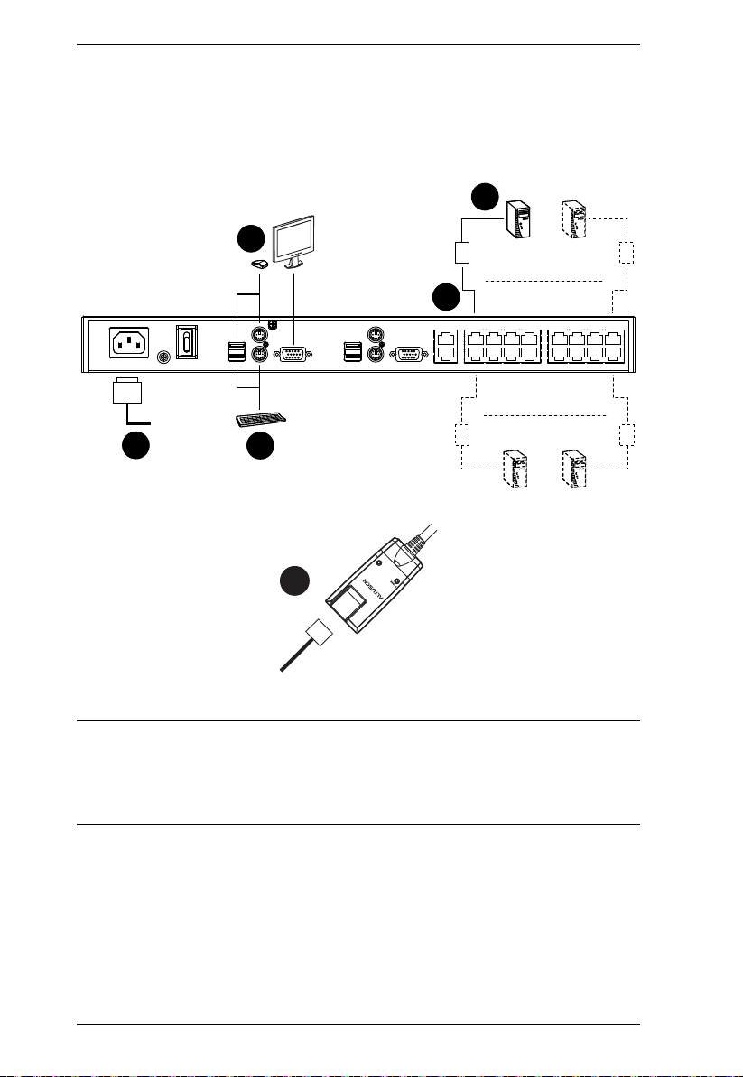
Single Level Installation
In a single level installation, there are no additional KVM switches cascaded
from the first-level KVM switch. To set up a single level installation, refer to
the diagram on page 18 and do the following:
1. Plug a keyboard, monitor, and mouse into the KH2508 / KH2516’s
Console 1 ports. Each port is color coded and marked with an identifying
icon. A second keyboard, monitor, and mouse can be connected to the
KH2508 / KH2516’s Console 2 ports.
2. Plug the KVM adapter cable connectors into the appropriate ports of the
computer you are installing. (See KVM Adapter Cable Installation
Diagrams, page 19 for connection examples.)
3. Use Cat 5e cable to connect a compatible KVM adapter cable to any
available KVM port on the KH2508 / KH2516. (Repeat steps 2 and 3 for
all computers that you wish to connect. Up to 8 or 16 computers may be
connected in this fashion.)
Note: The distance between any KVM adapter cable and switch must not
exceed 40 m (130 feet).
4. Plug the power cord into the KH2508 / KH2516's power socket first, then
plug the power cord into an AC power source.
5. Turn on the power to the KH2508 / KH2516.
After the KH2508 / KH2516 is powered up, you can turn on the computers.
17
KH2508 / KH2516 User Manual
1
2
4
3
1
3
b
y ATEN
PS/2 CPU MODUL
E
MODEL
NO. KA9120
PS/2 CPU MODUL
E
MODEL
NO. KA9120
LIN
K
Single Level Installation Diagram
Note: 1. Although the KH2516 is pictured in the diagram, the installation
process is the same for the KH2508.
2. The numbers in the diagrams correspond to the numbered steps of
Single Level Installation on the previous page.
18
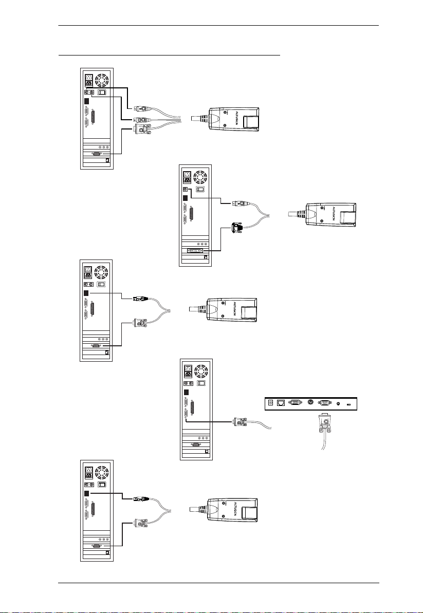
KVM Adapter Cable Installation Diagrams
KA9520
LIN
b
y A
K
TEN
KA9131
KA9170
LIN
b
y A
K
TEN
Chapter 2. Hardware Setup
KA9130
LIN
b
y A
K
TEN
LIN
K
KA9570
b
y A
TEN
KA9140
SERIAL TERMINAL
19
 Loading...