

Cat 5 High-Density KVM Over the NET™
KH1508i / KH1516i
User Manual
www.aten.com
KH1508i / KH1516i User Manual
FCC Information
This is an FCC Class A product. In a domestic environment this product may
cause radio interference in which case the user may be required to take
adequate measures.
This equipment has been tested and found to comply with the limits for a Class
A digital device, pursuant to Part 15 of the FCC Rules. These limits are
designed to provide reasonable protection against harmful interference when
the equipment is operated in a commercial environment. This equipment
generates, uses and can radiate radio frequency energy and, if not installed and
used in accordance with the instruction manual, may cause harmful
interference to radio communications. Operation of this equipment in a
residential area is likely to cause harmful interference in which case the user
will be required to correct the interference at his own expense.
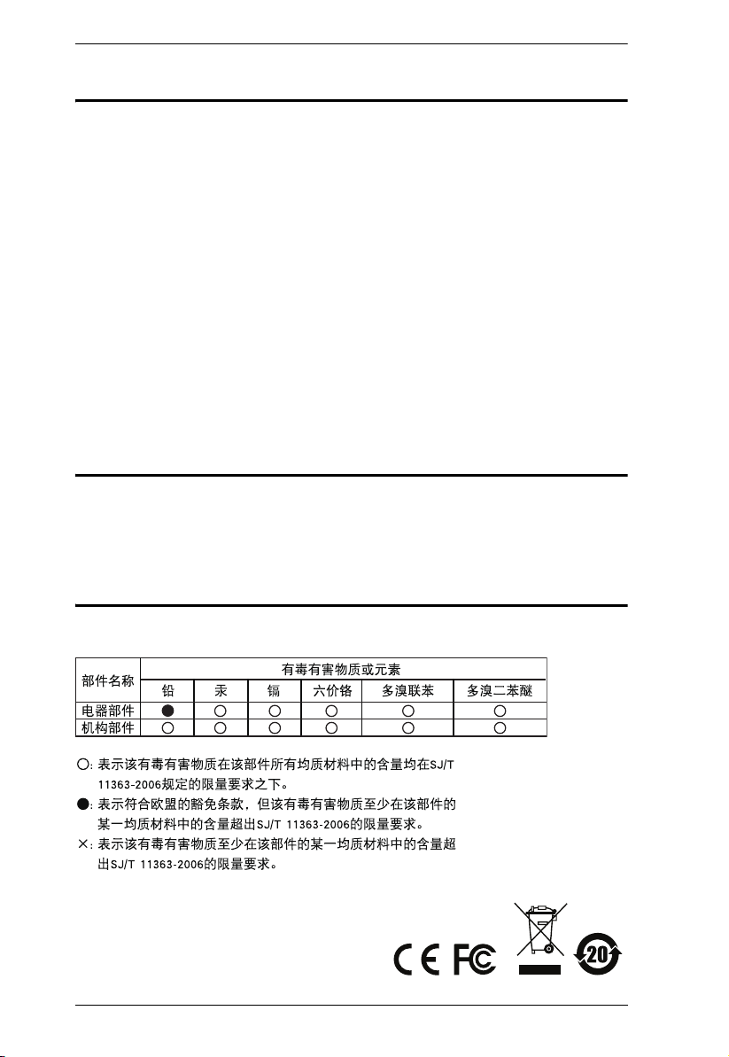
RoHS
This product is RoHS compliant.
SJ/T 11364-2006
The following contains information that relates to China.
ii

KH1508i / KH1516i User Manual
User Information
Online Registration
Be sure to register your product at our online support center:
International http://support.aten.com
North America ATEN TECH http://www.aten-usa.com/product_registration
ATEN NJ http://support.aten.com
Telephone Support
For telephone support, call this number:
International 886-2-8692-6959
North America ATEN TECH 1-888-999-ATEN
ATEN NJ 1-732-356-1703
User Notice
All information, documentation, and specifications contained in this manual
are subject to change without prior notification by the manufacturer. The
manufacturer makes no representations or warranties, either expressed or
implied, with respect to the contents hereof and specifically disclaims any
warranties as to merchantability or fitness for any particular purpose. Any of
the manufacturer's software described in this manual is sold or licensed as is.
Should the programs prove defective following their purchase, the buyer (and
not the manufacturer, its distributor, or its dealer), assumes the entire cost of all
necessary servicing, repair and any incidental or consequential damages
resulting from any defect in the software.
The manufacturer of this system is not responsible for any radio and/or TV
interference caused by unauthorized modifications to this device. It is the
responsibility of the user to correct such interference.
The manufacturer is not responsible for any damage incurred in the operation
of this system if the correct operational voltage setting was not selected prior
to operation. PLEASE VERIFY THAT THE VOLTAGE SETTING IS
CORRECT BEFORE USE.
iii

KH1508i / KH1516i User Manual
Package Contents
The KH1508i / KH1516i package consists of:
1 KH1508i or KH1516i Cat 5 High-Density KVM Over the NET™ Switch
1 Firmware Upgrade Cable
1Power Cord
1 Rack Mount Kit
1 Foot Pad Set (4 pcs.)
1 User Manual*
1 Quick Start Guide
Check to make sure that all of the components are present and in good order.
If anything is missing, or was damaged in shipping, contact your dealer.
Read this manual thoroughly and follow the installation and operation
procedures carefully to prevent any damage to the switch or to any other
devices on the KH1508i / KH1516i installation.
* Features may have been added to the KH1508i / KH1516i since this manual
was printed. Please visit our website to download the most up-to-date version
of the manual.
Copyright © 2006 ATEN® International Co., Ltd.
Manual Part No. PAPE-0276-AX1G
Manual Date: 2008-07-25
Altusen and the Altusen logo are registered trademarks of ATEN International Co., Ltd. All rights reserved.
All other brand names and trademarks are the registered property of their respective owners.
iv

KH1508i / KH1516i User Manual
Contents
FCC Information . . . . . . . . . . . . . . . . . . . . . . . . . . . . . . . . . . . . . . . . . . . . . ii
SJ/T 11364-2006. . . . . . . . . . . . . . . . . . . . . . . . . . . . . . . . . . . . . . . . . . . . . ii
User Information . . . . . . . . . . . . . . . . . . . . . . . . . . . . . . . . . . . . . . . . . . . . .iii
Online Registration . . . . . . . . . . . . . . . . . . . . . . . . . . . . . . . . . . . . . . . .iii
Telephone Support . . . . . . . . . . . . . . . . . . . . . . . . . . . . . . . . . . . . . . . .iii
User Notice . . . . . . . . . . . . . . . . . . . . . . . . . . . . . . . . . . . . . . . . . . . . . .iii
Package Contents. . . . . . . . . . . . . . . . . . . . . . . . . . . . . . . . . . . . . . . . . . . iv
About This Manual . . . . . . . . . . . . . . . . . . . . . . . . . . . . . . . . . . . . . . . . . . xi
Overview . . . . . . . . . . . . . . . . . . . . . . . . . . . . . . . . . . . . . . . . . . . . . . . xi
Conventions . . . . . . . . . . . . . . . . . . . . . . . . . . . . . . . . . . . . . . . . . . . . xii
Product Information. . . . . . . . . . . . . . . . . . . . . . . . . . . . . . . . . . . . . . . . . . xii
Chapter 1.
Introduction
Overview . . . . . . . . . . . . . . . . . . . . . . . . . . . . . . . . . . . . . . . . . . . . . . . . . . .1
Features . . . . . . . . . . . . . . . . . . . . . . . . . . . . . . . . . . . . . . . . . . . . . . . . . . .3
Requirements . . . . . . . . . . . . . . . . . . . . . . . . . . . . . . . . . . . . . . . . . . . . . . . 4
General . . . . . . . . . . . . . . . . . . . . . . . . . . . . . . . . . . . . . . . . . . . . . . . . .4
Console . . . . . . . . . . . . . . . . . . . . . . . . . . . . . . . . . . . . . . . . . . . . . . . . .4
Computers. . . . . . . . . . . . . . . . . . . . . . . . . . . . . . . . . . . . . . . . . . . . . . .4
KVM Adapter Cables. . . . . . . . . . . . . . . . . . . . . . . . . . . . . . . . . . . . . . . 5
Supported Operating Systems . . . . . . . . . . . . . . . . . . . . . . . . . . . . . . .5
Language Support. . . . . . . . . . . . . . . . . . . . . . . . . . . . . . . . . . . . . . . . .5
Components . . . . . . . . . . . . . . . . . . . . . . . . . . . . . . . . . . . . . . . . . . . . . . . . 6
Front View . . . . . . . . . . . . . . . . . . . . . . . . . . . . . . . . . . . . . . . . . . . . . . .6
KH1508i . . . . . . . . . . . . . . . . . . . . . . . . . . . . . . . . . . . . . . . . . . . . . .6
KH1516i . . . . . . . . . . . . . . . . . . . . . . . . . . . . . . . . . . . . . . . . . . . . . .6
Rear View . . . . . . . . . . . . . . . . . . . . . . . . . . . . . . . . . . . . . . . . . . . . . . .8
KH1508i . . . . . . . . . . . . . . . . . . . . . . . . . . . . . . . . . . . . . . . . . . . . . .8
KH1516i . . . . . . . . . . . . . . . . . . . . . . . . . . . . . . . . . . . . . . . . . . . . . .8
Chapter 2.
Hardware Setup
Overview . . . . . . . . . . . . . . . . . . . . . . . . . . . . . . . . . . . . . . . . . . . . . . . . . . .9
Before You Begin . . . . . . . . . . . . . . . . . . . . . . . . . . . . . . . . . . . . . . . . . . . . 9
Stacking and Rack Mounting . . . . . . . . . . . . . . . . . . . . . . . . . . . . . . . . . .10
Stacking. . . . . . . . . . . . . . . . . . . . . . . . . . . . . . . . . . . . . . . . . . . . . . . .10
Rack Mounting . . . . . . . . . . . . . . . . . . . . . . . . . . . . . . . . . . . . . . . . . .11
Single Station Installation . . . . . . . . . . . . . . . . . . . . . . . . . . . . . . . . . . . . .12
Single Stage Installation Diagram . . . . . . . . . . . . . . . . . . . . . . . . . . . . 13
KVM Adapter Cable Installation Diagrams . . . . . . . . . . . . . . . . . . . . . 14
Daisy Chaining . . . . . . . . . . . . . . . . . . . . . . . . . . . . . . . . . . . . . . . . . . . . . 15
Daisy Chain Installation Diagram . . . . . . . . . . . . . . . . . . . . . . . . . . . .16
v

KH1508i / KH1516i User Manual
Chapter 3.
Basic Operation
Port Selection . . . . . . . . . . . . . . . . . . . . . . . . . . . . . . . . . . . . . . . . . . . . . . 17
Manual . . . . . . . . . . . . . . . . . . . . . . . . . . . . . . . . . . . . . . . . . . . . . . . . 17
OSD . . . . . . . . . . . . . . . . . . . . . . . . . . . . . . . . . . . . . . . . . . . . . . . . . . 17
Keyboard Hotkeys. . . . . . . . . . . . . . . . . . . . . . . . . . . . . . . . . . . . . . . . 17
Hot Plugging . . . . . . . . . . . . . . . . . . . . . . . . . . . . . . . . . . . . . . . . . . . . . . . 18
Hot Plugging Stations . . . . . . . . . . . . . . . . . . . . . . . . . . . . . . . . . . . . . 18
Hot Plugging KVM Ports . . . . . . . . . . . . . . . . . . . . . . . . . . . . . . . . . . . 18
Hot Plugging Console Ports: . . . . . . . . . . . . . . . . . . . . . . . . . . . . . . . . 18
Powering Off and Restarting. . . . . . . . . . . . . . . . . . . . . . . . . . . . . . . . . . . 19
Port ID Numbering . . . . . . . . . . . . . . . . . . . . . . . . . . . . . . . . . . . . . . . . . . 19
Chapter 4.
Local Console Operation
Overview. . . . . . . . . . . . . . . . . . . . . . . . . . . . . . . . . . . . . . . . . . . . . . . . . . 21
The OSD Main Screen . . . . . . . . . . . . . . . . . . . . . . . . . . . . . . . . . . . . . . . 22
OSD Navigation . . . . . . . . . . . . . . . . . . . . . . . . . . . . . . . . . . . . . . . . . . . . 23
OSD Main Screen Headings. . . . . . . . . . . . . . . . . . . . . . . . . . . . . . . . . . . 23
OSD Functions . . . . . . . . . . . . . . . . . . . . . . . . . . . . . . . . . . . . . . . . . . . . . 24
F1 GOTO . . . . . . . . . . . . . . . . . . . . . . . . . . . . . . . . . . . . . . . . . . . . . . 24
F2 LIST . . . . . . . . . . . . . . . . . . . . . . . . . . . . . . . . . . . . . . . . . . . . . . . . 25
F3 SET . . . . . . . . . . . . . . . . . . . . . . . . . . . . . . . . . . . . . . . . . . . . . . . . 26
F4 ADM. . . . . . . . . . . . . . . . . . . . . . . . . . . . . . . . . . . . . . . . . . . . . . . . 29
F5 SKP . . . . . . . . . . . . . . . . . . . . . . . . . . . . . . . . . . . . . . . . . . . . . . . . 31
F6 IP . . . . . . . . . . . . . . . . . . . . . . . . . . . . . . . . . . . . . . . . . . . . . . . . . . 32
F7 SCAN. . . . . . . . . . . . . . . . . . . . . . . . . . . . . . . . . . . . . . . . . . . . . . . 32
F8 LOUT . . . . . . . . . . . . . . . . . . . . . . . . . . . . . . . . . . . . . . . . . . . . . . . 33
Keyboard Port Operation . . . . . . . . . . . . . . . . . . . . . . . . . . . . . . . . . . . . . 34
Overview . . . . . . . . . . . . . . . . . . . . . . . . . . . . . . . . . . . . . . . . . . . . . . . 34
Invoking Hotkey Mode. . . . . . . . . . . . . . . . . . . . . . . . . . . . . . . . . . . . . 34
When Hotkey Mode is active: . . . . . . . . . . . . . . . . . . . . . . . . . . . . 35
Selecting the Active Port. . . . . . . . . . . . . . . . . . . . . . . . . . . . . . . . . . . 35
Auto Scanning. . . . . . . . . . . . . . . . . . . . . . . . . . . . . . . . . . . . . . . . . . . 36
Setting the Scan Interval . . . . . . . . . . . . . . . . . . . . . . . . . . . . . . . . 36
Invoking Auto Scan . . . . . . . . . . . . . . . . . . . . . . . . . . . . . . . . . . . . 37
Skip Mode . . . . . . . . . . . . . . . . . . . . . . . . . . . . . . . . . . . . . . . . . . . . . . 38
Hotkey Beeper Control . . . . . . . . . . . . . . . . . . . . . . . . . . . . . . . . . . . . 39
Hotkey Summary Table. . . . . . . . . . . . . . . . . . . . . . . . . . . . . . . . . . . . 39
Firmware Upgrade . . . . . . . . . . . . . . . . . . . . . . . . . . . . . . . . . . . . . . . . . . 40
KH1508i / KH1516i Mainboard Upgrade. . . . . . . . . . . . . . . . . . . . . . . 40
Before You Begin . . . . . . . . . . . . . . . . . . . . . . . . . . . . . . . . . . . . . 40
Starting the Upgrade . . . . . . . . . . . . . . . . . . . . . . . . . . . . . . . . . . . 41
Upgrade Succeeded:. . . . . . . . . . . . . . . . . . . . . . . . . . . . . . . . . . . 44
Upgrade Failed:. . . . . . . . . . . . . . . . . . . . . . . . . . . . . . . . . . . . . . . 44
Firmware Upgrade Recovery . . . . . . . . . . . . . . . . . . . . . . . . . . . . . . . 45
vi

KH1508i / KH1516i User Manual
Adapter Cable Upgrade. . . . . . . . . . . . . . . . . . . . . . . . . . . . . . . . . . . .46
Before You Begin. . . . . . . . . . . . . . . . . . . . . . . . . . . . . . . . . . . . . . 46
Starting the Upgrade:. . . . . . . . . . . . . . . . . . . . . . . . . . . . . . . . . . .47
Upgrade Succeeded: . . . . . . . . . . . . . . . . . . . . . . . . . . . . . . . . . . .48
Adapter Cable Firmware Upgrade Recovery . . . . . . . . . . . . . . . . . . .49
Chapter 5.
Browser Login
Logging In . . . . . . . . . . . . . . . . . . . . . . . . . . . . . . . . . . . . . . . . . . . . . . . . .51
Web Page Layout . . . . . . . . . . . . . . . . . . . . . . . . . . . . . . . . . . . . . . . . . . .53
The General Dialog Box . . . . . . . . . . . . . . . . . . . . . . . . . . . . . . . . . . .53
Web Page Icons . . . . . . . . . . . . . . . . . . . . . . . . . . . . . . . . . . . . . . . . .54
Web Page Buttons . . . . . . . . . . . . . . . . . . . . . . . . . . . . . . . . . . . . . . .55
Upgrading the Browser Firmware . . . . . . . . . . . . . . . . . . . . . . . . . . . . . . .56
Activating the OSD . . . . . . . . . . . . . . . . . . . . . . . . . . . . . . . . . . . . . . . . . .57
Windows Client . . . . . . . . . . . . . . . . . . . . . . . . . . . . . . . . . . . . . . . . . . 57
Java Client. . . . . . . . . . . . . . . . . . . . . . . . . . . . . . . . . . . . . . . . . . . . . . 60
Chapter 6.
Administration and Configuration
The Administration Page. . . . . . . . . . . . . . . . . . . . . . . . . . . . . . . . . . . . . .63
General . . . . . . . . . . . . . . . . . . . . . . . . . . . . . . . . . . . . . . . . . . . . . . . .64
User Management. . . . . . . . . . . . . . . . . . . . . . . . . . . . . . . . . . . . . . . . 65
Port Access . . . . . . . . . . . . . . . . . . . . . . . . . . . . . . . . . . . . . . . . . .67
Service Configuration . . . . . . . . . . . . . . . . . . . . . . . . . . . . . . . . . . . . .69
Access Port . . . . . . . . . . . . . . . . . . . . . . . . . . . . . . . . . . . . . . . . . . 69
Log Server . . . . . . . . . . . . . . . . . . . . . . . . . . . . . . . . . . . . . . . . . . .70
Network . . . . . . . . . . . . . . . . . . . . . . . . . . . . . . . . . . . . . . . . . . . . . . . . 71
Network Transfer Rate. . . . . . . . . . . . . . . . . . . . . . . . . . . . . . . . . .71
IP Address . . . . . . . . . . . . . . . . . . . . . . . . . . . . . . . . . . . . . . . . . . .71
DNS Server . . . . . . . . . . . . . . . . . . . . . . . . . . . . . . . . . . . . . . . . . . 71
Radius . . . . . . . . . . . . . . . . . . . . . . . . . . . . . . . . . . . . . . . . . . . . . . . . .72
RADIUS Server Access Rights Table:. . . . . . . . . . . . . . . . . . . . . .73
RADIUS Server Access Rights Examples: . . . . . . . . . . . . . . . . . .74
Security . . . . . . . . . . . . . . . . . . . . . . . . . . . . . . . . . . . . . . . . . . . . . . . .75
IP and MAC Filtering . . . . . . . . . . . . . . . . . . . . . . . . . . . . . . . . . . .75
Default Web Page Name. . . . . . . . . . . . . . . . . . . . . . . . . . . . . . . .76
Customization . . . . . . . . . . . . . . . . . . . . . . . . . . . . . . . . . . . . . . . . . . . 77
Login Failures . . . . . . . . . . . . . . . . . . . . . . . . . . . . . . . . . . . . . . . .77
Working Mode . . . . . . . . . . . . . . . . . . . . . . . . . . . . . . . . . . . . . . . . 77
I/O Modules . . . . . . . . . . . . . . . . . . . . . . . . . . . . . . . . . . . . . . . . . .78
Miscellaneous . . . . . . . . . . . . . . . . . . . . . . . . . . . . . . . . . . . . . . . . . . .79
The Configuration Page . . . . . . . . . . . . . . . . . . . . . . . . . . . . . . . . . . . . . .80
vii

KH1508i / KH1516i User Manual
Chapter 7.
Windows Client Port Operation
Windows Client Control Panel . . . . . . . . . . . . . . . . . . . . . . . . . . . . . . . . . 84
Hotkey Setup. . . . . . . . . . . . . . . . . . . . . . . . . . . . . . . . . . . . . . . . . . . . 85
Video Adjustment . . . . . . . . . . . . . . . . . . . . . . . . . . . . . . . . . . . . . . . . 87
Gamma Adjustment. . . . . . . . . . . . . . . . . . . . . . . . . . . . . . . . . . . . 89
The Message Board . . . . . . . . . . . . . . . . . . . . . . . . . . . . . . . . . . . . . . 90
The Button Bar . . . . . . . . . . . . . . . . . . . . . . . . . . . . . . . . . . . . . . . 91
Message Display Panel. . . . . . . . . . . . . . . . . . . . . . . . . . . . . . . . . 91
Compose Panel. . . . . . . . . . . . . . . . . . . . . . . . . . . . . . . . . . . . . . . 91
User List Panel . . . . . . . . . . . . . . . . . . . . . . . . . . . . . . . . . . . . . . . 92
The Main Page . . . . . . . . . . . . . . . . . . . . . . . . . . . . . . . . . . . . . . . . . . . . . 93
Quick View Ports. . . . . . . . . . . . . . . . . . . . . . . . . . . . . . . . . . . . . . . . . 93
The List Function. . . . . . . . . . . . . . . . . . . . . . . . . . . . . . . . . . . . . . . . . 94
Port Names . . . . . . . . . . . . . . . . . . . . . . . . . . . . . . . . . . . . . . . . . . . . . 96
Port Operation . . . . . . . . . . . . . . . . . . . . . . . . . . . . . . . . . . . . . . . . . . . . . 98
The OSD Toolbar . . . . . . . . . . . . . . . . . . . . . . . . . . . . . . . . . . . . . . . . 98
Recalling the OSD. . . . . . . . . . . . . . . . . . . . . . . . . . . . . . . . . . . . . . . . 98
OSD Hotkey Summary Table . . . . . . . . . . . . . . . . . . . . . . . . . . . . . . . 99
OSD Toolbar Icons . . . . . . . . . . . . . . . . . . . . . . . . . . . . . . . . . . . . . . . 99
Panel Array Mode . . . . . . . . . . . . . . . . . . . . . . . . . . . . . . . . . . . . . . . 100
Panel Array Toolbar . . . . . . . . . . . . . . . . . . . . . . . . . . . . . . . . . . 101
Multiuser Operation . . . . . . . . . . . . . . . . . . . . . . . . . . . . . . . . . . . . . . . . 102
Keyboard Hotkey Operation . . . . . . . . . . . . . . . . . . . . . . . . . . . . . . . . . . 103
Auto Scanning. . . . . . . . . . . . . . . . . . . . . . . . . . . . . . . . . . . . . . . . . . 103
Setting the Scan Interval. . . . . . . . . . . . . . . . . . . . . . . . . . . . . . . . . . 103
Invoking Auto Scan . . . . . . . . . . . . . . . . . . . . . . . . . . . . . . . . . . . . . . 103
Pausing Auto Scan . . . . . . . . . . . . . . . . . . . . . . . . . . . . . . . . . . . . . . 104
Exiting Auto Scan . . . . . . . . . . . . . . . . . . . . . . . . . . . . . . . . . . . . . . . 104
Skip Mode . . . . . . . . . . . . . . . . . . . . . . . . . . . . . . . . . . . . . . . . . . . . . 104
Keyboard and Mouse Considerations. . . . . . . . . . . . . . . . . . . . . . . . . . . 105
Keystrokes . . . . . . . . . . . . . . . . . . . . . . . . . . . . . . . . . . . . . . . . . . . . 105
Mouse Synchronization. . . . . . . . . . . . . . . . . . . . . . . . . . . . . . . . . . . 106
Chapter 8.
Java Client Port Operation
The Java Client Control Panel . . . . . . . . . . . . . . . . . . . . . . . . . . . . . . . . 108
Set Video Parameters . . . . . . . . . . . . . . . . . . . . . . . . . . . . . . . . . . . . 108
Keypad . . . . . . . . . . . . . . . . . . . . . . . . . . . . . . . . . . . . . . . . . . . . . . . 109
Mouse Synchronization. . . . . . . . . . . . . . . . . . . . . . . . . . . . . . . . . . . 109
Message Board. . . . . . . . . . . . . . . . . . . . . . . . . . . . . . . . . . . . . . . . . 110
The Message Board Button Bar . . . . . . . . . . . . . . . . . . . . . . . . . 111
Lock Key LEDs and Resolution. . . . . . . . . . . . . . . . . . . . . . . . . . . . . 113
Switch Screen Mode . . . . . . . . . . . . . . . . . . . . . . . . . . . . . . . . . . . . . 113
About. . . . . . . . . . . . . . . . . . . . . . . . . . . . . . . . . . . . . . . . . . . . . . . . . 113
Send Ctrl+Alt+Del . . . . . . . . . . . . . . . . . . . . . . . . . . . . . . . . . . . . . . . 113
viii

KH1508i / KH1516i User Manual
Help . . . . . . . . . . . . . . . . . . . . . . . . . . . . . . . . . . . . . . . . . . . . . . . . . . 113
Exit . . . . . . . . . . . . . . . . . . . . . . . . . . . . . . . . . . . . . . . . . . . . . . . . . . 113
Port Operation. . . . . . . . . . . . . . . . . . . . . . . . . . . . . . . . . . . . . . . . . . . . .114
Panel Array Mode . . . . . . . . . . . . . . . . . . . . . . . . . . . . . . . . . . . . . . .114
Keyboard Hotkey Operation . . . . . . . . . . . . . . . . . . . . . . . . . . . . . . . . . . 115
Chapter 9.
The Log File
The Main Screen. . . . . . . . . . . . . . . . . . . . . . . . . . . . . . . . . . . . . . . . . . .117
Chapter 10.
The Log Server
Installation. . . . . . . . . . . . . . . . . . . . . . . . . . . . . . . . . . . . . . . . . . . . . . . .119
Starting Up . . . . . . . . . . . . . . . . . . . . . . . . . . . . . . . . . . . . . . . . . . . . . . . 120
The Menu Bar . . . . . . . . . . . . . . . . . . . . . . . . . . . . . . . . . . . . . . . . . . . . .121
Configure. . . . . . . . . . . . . . . . . . . . . . . . . . . . . . . . . . . . . . . . . . . . . .121
Events . . . . . . . . . . . . . . . . . . . . . . . . . . . . . . . . . . . . . . . . . . . . . . . . 122
Search . . . . . . . . . . . . . . . . . . . . . . . . . . . . . . . . . . . . . . . . . . . . . 122
Maintenance . . . . . . . . . . . . . . . . . . . . . . . . . . . . . . . . . . . . . . . .124
Options . . . . . . . . . . . . . . . . . . . . . . . . . . . . . . . . . . . . . . . . . . . . . . . 124
Help . . . . . . . . . . . . . . . . . . . . . . . . . . . . . . . . . . . . . . . . . . . . . . . . . . 124
The Log Server Main Screen . . . . . . . . . . . . . . . . . . . . . . . . . . . . . . . . .125
Overview . . . . . . . . . . . . . . . . . . . . . . . . . . . . . . . . . . . . . . . . . . . . . .125
The List Panel . . . . . . . . . . . . . . . . . . . . . . . . . . . . . . . . . . . . . . . . . .126
The Event Panel . . . . . . . . . . . . . . . . . . . . . . . . . . . . . . . . . . . . . . . . 126
Chapter 11.
AP Operation
The Windows Client . . . . . . . . . . . . . . . . . . . . . . . . . . . . . . . . . . . . . . . .127
Installation . . . . . . . . . . . . . . . . . . . . . . . . . . . . . . . . . . . . . . . . . . . . .127
Starting Up . . . . . . . . . . . . . . . . . . . . . . . . . . . . . . . . . . . . . . . . . . . .128
Keyboard . . . . . . . . . . . . . . . . . . . . . . . . . . . . . . . . . . . . . . . . . . . 130
Connecting . . . . . . . . . . . . . . . . . . . . . . . . . . . . . . . . . . . . . . . . . . . . 132
Operation. . . . . . . . . . . . . . . . . . . . . . . . . . . . . . . . . . . . . . . . . . . . . . 133
Ending the Session . . . . . . . . . . . . . . . . . . . . . . . . . . . . . . . . . . . . . . 133
The Java Client . . . . . . . . . . . . . . . . . . . . . . . . . . . . . . . . . . . . . . . . . . . . 134
Installation . . . . . . . . . . . . . . . . . . . . . . . . . . . . . . . . . . . . . . . . . . . . .134
Starting Up . . . . . . . . . . . . . . . . . . . . . . . . . . . . . . . . . . . . . . . . . . . .134
Operation. . . . . . . . . . . . . . . . . . . . . . . . . . . . . . . . . . . . . . . . . . . . . . 136
Chapter 12.
Keyboard Emulation
Mac Keyboard . . . . . . . . . . . . . . . . . . . . . . . . . . . . . . . . . . . . . . . . . . . . .137
Sun Keyboard . . . . . . . . . . . . . . . . . . . . . . . . . . . . . . . . . . . . . . . . . . . . .138
ix

KH1508i / KH1516i User Manual
Appendix
Safety Instructions . . . . . . . . . . . . . . . . . . . . . . . . . . . . . . . . . . . . . . . . . 139
General . . . . . . . . . . . . . . . . . . . . . . . . . . . . . . . . . . . . . . . . . . . . . . . 139
Rack Mounting . . . . . . . . . . . . . . . . . . . . . . . . . . . . . . . . . . . . . . . . . 141
Technical Support. . . . . . . . . . . . . . . . . . . . . . . . . . . . . . . . . . . . . . . . . . 142
International . . . . . . . . . . . . . . . . . . . . . . . . . . . . . . . . . . . . . . . . . . . 142
North America . . . . . . . . . . . . . . . . . . . . . . . . . . . . . . . . . . . . . . . . . . 142
Troubleshooting . . . . . . . . . . . . . . . . . . . . . . . . . . . . . . . . . . . . . . . . . . . 143
Administration . . . . . . . . . . . . . . . . . . . . . . . . . . . . . . . . . . . . . . . . . . 143
General Operation. . . . . . . . . . . . . . . . . . . . . . . . . . . . . . . . . . . . . . . 143
The Java Client . . . . . . . . . . . . . . . . . . . . . . . . . . . . . . . . . . . . . . . . . 144
The Log Server . . . . . . . . . . . . . . . . . . . . . . . . . . . . . . . . . . . . . . . . . 144
Panel Array Mode . . . . . . . . . . . . . . . . . . . . . . . . . . . . . . . . . . . . . . . 145
The Windows Client . . . . . . . . . . . . . . . . . . . . . . . . . . . . . . . . . . . . . 145
Sun Systems. . . . . . . . . . . . . . . . . . . . . . . . . . . . . . . . . . . . . . . . . . . 146
Additional Mouse Synchronization Procedures. . . . . . . . . . . . . . . . . 147
Specifications . . . . . . . . . . . . . . . . . . . . . . . . . . . . . . . . . . . . . . . . . . . . . 149
Trusted Certificates. . . . . . . . . . . . . . . . . . . . . . . . . . . . . . . . . . . . . . . . . 150
Overview . . . . . . . . . . . . . . . . . . . . . . . . . . . . . . . . . . . . . . . . . . . . . . 150
Installing the Certificate. . . . . . . . . . . . . . . . . . . . . . . . . . . . . . . . . . . 151
Certificate Trusted. . . . . . . . . . . . . . . . . . . . . . . . . . . . . . . . . . . . . . . 152
Supported Devices . . . . . . . . . . . . . . . . . . . . . . . . . . . . . . . . . . . . . . . . . 153
OSD Factory Default Settings. . . . . . . . . . . . . . . . . . . . . . . . . . . . . . . . . 153
Administrator Login Failure. . . . . . . . . . . . . . . . . . . . . . . . . . . . . . . . . . . 154
IP Module Firmware Upgrade Recovery. . . . . . . . . . . . . . . . . . . . . . . . . 155
Limited Warranty. . . . . . . . . . . . . . . . . . . . . . . . . . . . . . . . . . . . . . . . . . . 156
x

KH1508i / KH1516i User Manual
About This Manual
This User Manual is provided to help you get the most from your KH1508i /
KH1516i system. It covers all aspects of installation, configuration and
operation. An overview of the information found in the manual is provided
below.
Overview
Chapter 1, Introduction, introduces you to the KH1508i / KH1516i
system. Its purpose, features and benefits are presented, and its front and back
panel components are described.
Chapter 2, Hardware Setup, describes how to set up your installation. The
necessary steps – from a basic single stage hookup to a complete 16 switch
daisy chained operation are provided.
Chapter 3, Basic Operation, explains the fundamental concepts involved
in operating the KH1508i / KH1516i.
Chapter 4, Local Console Operation, describes the concepts and
procedures used to operate the KH1508i / KH1516i from a locally connected
KVM console.
Chapter 5, Browser Login, explains how to log into the KH1508i /
KH1516i with your browser, and explains the functions of the icons and
buttons on the KH1508i / KH1516i web page.
Chapter 6, Administration and Configuration, describes how to
administer the KH1508i / KH1516i after logging in from a browser.
Chapter 7, Windows Client Port Operation, explains how to connect to
the KH1508i / KH1516i with the Windows Client software, and describes how
to use the OSD to access and control the computers connected to the switch.
Chapter 8, The Java Client Control Panel, describes how to connect to
the KH1508i / KH1516i with the Java Client software, and explains how to use
the OSD to access and control the computers connected to the switch.
Chapter 9, The Log File, shows how to use the log file utility to view all the
events that take place on the KH1508i / KH1516i.
Chapter 10, The Log Server, explains how to install and configure the
Log Server.
Chapter 11, AP Operation, describes how to operate the KH1508i /
KH1516i using Windows and Java Client application programs, rather than
with the browser method.
xi

KH1508i / KH1516i User Manual
Chapter 12, Keyboard Emulation, provides tables that list the PC to Mac
and PC to Sun keyboard emulation mappings.
An Appendix, provides specifications and other technical information
regarding the KH1508i / KH1516i.
Conventions
This manual uses the following conventions:
Monospaced Indicates text that you should key in.
[ ]
1.
♦
→
Indicates keys you should press. For example, [Enter] means
to press the Enter key. If keys need to be chorded, they appear
together in the same bracket with a plus sign between them:
[Ctrl+Alt].
Numbered lists represent procedures with sequential steps.
Bullet lists provide information, but do not involve sequential
steps.
Indicates selecting the option (on a menu or dialog box, for
example), that comes next. For example, Start
to open the Start menu, and then select Run.
Indicates critical information.
→ Run means
Product Information
For information about all ALTUSEN products and how they can help you
connect without limits, visit ALTUSEN on the Web or contact an ALTUSEN
Authorized Reseller. Visit ALTUSEN on the Web for a list of locations and
telephone numbers
International – http://www.aten.com
North America – http://www.aten-usa.com
xii
Chapter 1
Introduction
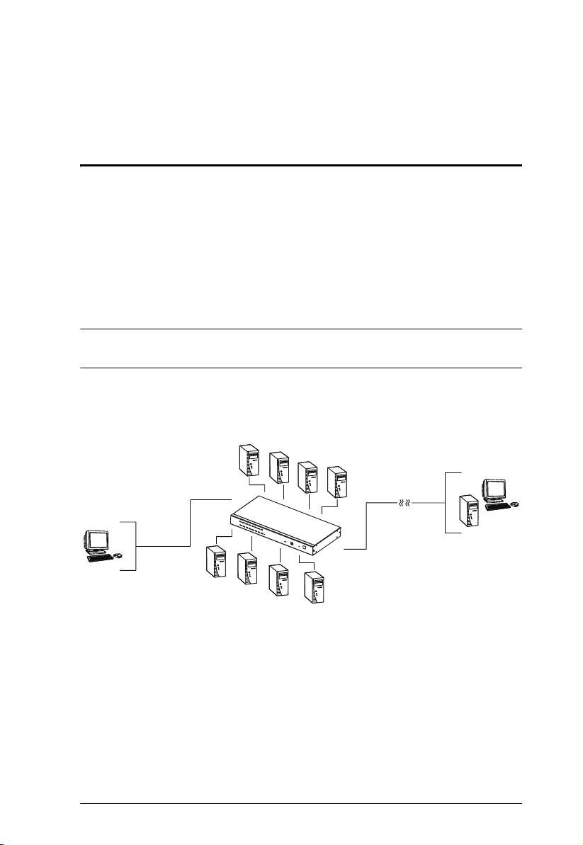
Overview
The KH1508i / KH1516i KVM Switches are control units that allow access to
multiple computers from a single KVM (keyboard, monitor, and mouse)
console.
A single KH1508i / KH1516i can control up to 8 / 16 computers. As many as
15 additional KH1508 / KH1516 switches can be daisy chained from the
original unit, so that up to 256 computers can all be controlled from the original
KVM console.
Note: Aten ACS1208 / ACS1216 switches can also be installed on a KH1508i
/ KH1516i daisy chain.
Since the KH1508i / KH1516i uses TCP/IP for its communications protocol, it
can be accessed from any computer on the Net - whether that computer is
located down the hall, down the street, or half-way around the world.
Over the
TM
NET
Local
In addition to TCP/IP connectivity, the KH1508i / KH1516i provides KVM
ports for a locally attached PS/2 console – allowing access and control from the
data center as well as over the Net. The switches utilize a single shared bus
implementation – although they support local and remote login at the same
time, they do not support independent operation. If a local user logs in while a
remote user has already opened a session, the local user sees the same screen
that the remote user is working on.
1

KH1508i / KH1516i User Manual
For local access, the KH1508i / KH1516i supports resolutions of up to 1600 x
1200, as well as 1280 x 1024 @ 75Hz for an extended distance of up to 40 m.
For remote access, the switches support up to 1280 x 1024 @ 75Hz.
The switches feature RJ-45 connectors and CAT 5 cable to link to the
computers. Utilizing PS/2, USB, and serial KVM Adapter Cables for the final
linkup, the KH1508i / KH1516i permits any combination of PCs, Macs, Sun
computers, and serial devices to coexist on the installation. Use of the adapter
cables dramatically reduces cable clutter, and makes reconfiguring the
installation easy and convenient.
A custom ASIC (patent pending) provides an auto-sensing function that
recognizes the position of each station on the chain, eliminating the need to
manually set the position with DIP switches. A seven segment front panel LED
displays each Station's position for easy identification.
The KH1508i / KH1516i has been designed to work seamlessly with the
ALTUSEN CC1000 Control Center Over the NET™ for ease of access and
administration. It also allows the IP address configuration to be easily
configured from the local console OSD.
Your KH1508i / KH1516i investment is protected by a firmware upgrade
utility. You can stay current with the latest improvements in functionality by
downloading firmware update files from our website, and using the utility to
quickly and conveniently install them.
Setting up the KH1508i / KH1516i is fast and easy; plugging cables into their
appropriate ports is all that is entailed. Because the KH1508i / KH1516i
intercepts keyboard and mouse input directly, there is no software to configure;
no need to get involved in complex installation routines; no need to be
concerned with incompatibility problems.
Access to any computer on the installation is easily accomplished--either by
pressing front panel port selection switches; entering hotkey combinations
from the keyboard; or by means of a powerful menu driven OSD (On Screen
Display) system. A convenient Auto Scan function also permits automatic
scanning and one-by-one monitoring of the activities of selected computers.
There is no better way to save time and money than with a KH1508i / KH1516i
installation. By allowing a single console to manage up to 256 computers, a
KH1508i / KH1516i installation: (1) eliminates the expense of having to
purchase a separate keyboard, monitor, and mouse for each; (2) saves all the
space those extra components would take up; (3) saves on energy costs; and (4)
eliminates the inconvenience and wasted effort involved in constantly moving
from one computer to another.
2

Chapter 1. Introduction
Features
A single console controls up to 8 (KH1508i) or 16 (KH1516i) computers
Dedicated chain ports - daisy chain up to 15 additional units - control up to
256 computers from a single console
Extends the distance between computers and switch - up to 30m for
resolutions of 1600 x 1200 @ 60Hz; up to 40 m for resolutions of 1280 x
1024 @ 75Hz
Custom ASIC (patent pending) auto-senses station's position on daisy
chained installations - no need for manual DIP switch setting - front panel
LED indicates station's position – port names automatically reconfigured
in the OSD when the station sequence changes
Multiplatform support: PC, Mac, Sun and terminal-based systems
Remote access via LAN, WAN, or the Internet – control your installation
from down the hall, down the street, or half-way around the world –
supports 10Base-T, 100Base-T, TCP/IP, HTTP
Allows the creation of up to 64 user accounts
Advanced security – password protection and advanced encryption
technologies
Windows and Java-based client software – Java client provides support for
most major operating platforms
No software required – convenient computer selection via port selection
switches, hotkeys and intuitive On Screen Display (OSD) menus
Auto Scan feature for monitoring user-selected computers
Hot Pluggable - add or remove switches/computers without having to
power down the switches
Two level logout - Manual and Timed
Upgradeable firmware
PS/2 keyboard and mouse emulation – computers boot even when the
console focus is elsewhere
Superior video quality – supports resolutions up to 1600 x 1200
Rack Mountable in 19" System Rack (1U)
3

KH1508i / KH1516i User Manual
Requirements
General
For best results, we recommend that the computers used to access the
KH1508i / KH1516i have at least a P III 1 GHz processor, and that their
screen resolution is set to 1024 x 768
For best results, we recommend an Internet connection speed of at least
128 kbps
Browsers must support 128 bit data encryption
To run the Windows client, you must have DirectX 7.0 or higher installed
To run the Java client, you must have Sun’s Java 2 (1.4 or higher) installed
To run the Log Server, you must have the Microsoft Jet OLEDB 4.0 (or
higher) driver installed
Console
A VGA, SVGA, or Multisync monitor capable of the highest resolution
that you will be using on any computer in the installation.
A PS/2 style mouse
A PS/2 style keyboard
Computers
The following equipment must be installed on the computers that connect to the
KH1508i or KH1516i's KVM ports:
A VGA, SVGA or Multisync port
A Type A USB port and USB host controller (for USB KVM Adapter
Cable Connection, see below)
6-pin mini-DIN keyboard and mouse ports (for PS/2 KVM Adapter Cable
Connection, see below)
4
Chapter 1. Introduction
KVM Adapter Cables
Cat 5 (or higher) cable is required to connect the KH1508i / KH1516i to a
KVM Adapter Cable (see Single Station Installation, page 12).
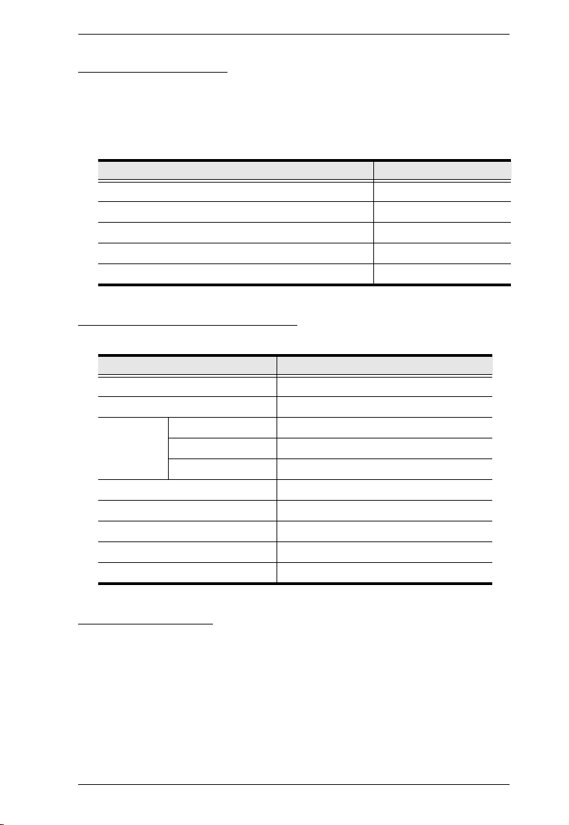
The following KVM Adapter Cables are required for use with the
KH1508i / KH1516i:
Function Module
Connect to devices with PS/2 ports KA9520
Connect to devices with USB ports KA9570
Connect to Sun Legacy systems (with 13W3 port) KA9130
Connect to Sun USB systems KA9131
Connect to serial based devices KA9140
Supported Operating Systems
The following operating systems are supported by the KH1508i / KH1516i:
OS Versi on
DOS 6.2 and higher
Windows 2000 and higher
Linux Red Hat 7.1 and higher
Mandrake/Mandriva 9.0 and higher
SUSE 8.2 and higher
Free BSD 4.2 and higher
AIX 4.3 and higher
Netware 5.0 and higher
Sun Solaris 8 and higher
Mac 8.6 and higher
Language Support
American English
French
German
Japanese
Traditional Chinese
UK English
5
KH1508i / KH1516i User Manual
Components
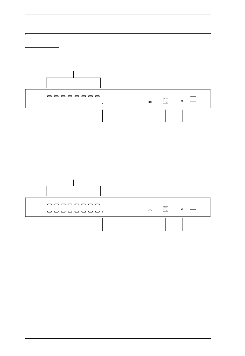
Front View
KH1508i
1&2
KH1516i
1&2
43 5
3567
4
67
6

Chapter 1. Introduction
Compo-
No.
1Port
nent
Selection
Switches
Press a switch to give the KVM focus to the computer attached
to its corresponding port.
Simultaneously pressing Buttons 1 and 2 for 3 seconds
performs a Keyboard and Mouse Reset.
Description
Simultaneously pressing Buttons 7 and 8 starts Auto Scan
Mode.
2 Port LEDs The Port LEDs are built into the Port Selection Switches. The left
ones are the On Line LEDs; the right ones are the Selected Port
LEDs:
An ONLINE LED lights GREEN to indicate that the computer
attached to its corresponding port is up and running. A flashing
LED indicates that the Port is being used for cascading to
another switch.
A SELECTED LED lights ORANGE to indicate that the
computer attached to its corresponding port is the one that has
the KVM focus. The LED is steady under normal conditions, but
flashes when its port is accessed under Auto Scan Mode.
3 Reset
Switch
4 Firmware
Upgrade
Recovery
Switch
5 Firmware
Upgrade
Port
6 Power LED Lights to indicate that the KH1508i / KH1516i is powered up and
7 Station ID
LED
Pressing this switch in performs a system reset.
Note: The switch is recessed and must be pushed with a thin
object - such as the end of a paper clip, or a ballpoint pen.
During normal operation and while performing a firmware
upgrade, this switch should be in the NORMAL position. If a
firmware upgrade operation does not complete successfully, this
switch is used to perform a firmware upgrade recovery.
Note: This is only for performing a local firmware upgrade
(see Firmware Upgrade Recovery, page 45) for details.
The Firmware Upgrade Cable that transfers the firmware upgrade
data from the administrator's computer to the KH1508i / KH1516i
(see page 40), plugs into this RJ-11 connector.
Note: This is only for performing a local firmware upgrade
(see Firmware Upgrade Recovery, page 45) for details.
ready to operate.
The KH1508i / KH1516i's Station ID is displayed here. If this is a
Single Station installation (see page 12), or the First Station on a
Daisy Chained installation (see page 15), the KH1508i / KH1516i
has a Station ID of 01.
On a Daisy Chained installation, the KH1508i / KH1516i auto-senses
its position and displays the Station ID that corresponds to its place in
the chain. (see Port ID Numbering, page 19, for details).
7
KH1508i / KH1516i User Manual
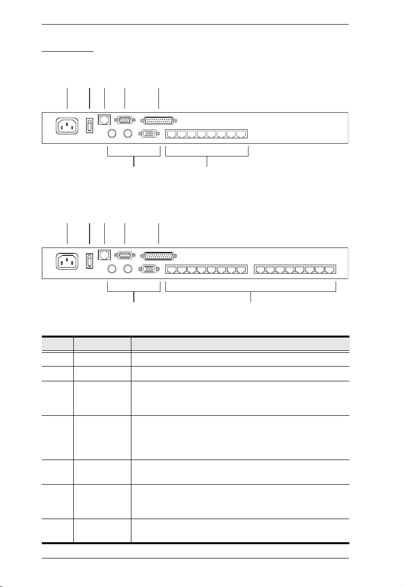
Rear View
KH1508i
12
34
5
76
KH1516i
1234 5
76
No. Component Description
1 Power Socket The AC power cord plugs in here.
2 Power Switch This rocker switch powers the unit on and off.
3 LAN Port The cable that connects the KH1508i / KH1516i to the
4 PON Port This connector is provided for a Power over the Net™ (PON)
5 Daisy Chain
Port
6 Local Console
Port Section
7 KVM Port
Section
Internet plugs in here. The LEDs indicate data transmission
speed: ORANGE for 10 Mbps; GREEN for 100 Mbps.
unit to plug into. A PON device allows computers attached to
the KH1508i / KH1516i to be booted remotely over the net.
Contact your dealer for more details.
When Daisy Chaining Units (see Daisy Chaining, page 15),
the daisy chain cable plugs in here.
If this is a Single Station installation, or if this is the First
Station of a daisy chained installation, the keyboard, monitor,
and mouse that make up the Local Console plug in here.
The Cat 5 cables that link to the KVM Adapter Cables (which
link to the computers) plug in here.
8

Chapter 2
Hardware Setup
Overview
For convenience and flexibility that allows mixing the PS/2, USB, and serial
device interfaces, as well as multiple platforms, the KH1508i / KH1516i's
design utilizes KVM Adapter Cables (CPU Modules), that serve as
intermediaries between the switch and the connected devices (refer to the
installation diagram on page 13).
A separate KVM Adapter Cable is required for each computer or device
connection. See KVM Adapter Cables, page 5 for the model numbers.
Before You Begin
1. Important safety information regarding the placement of this
device is provided on page 139. Please review it before
proceeding.
2. Make sure that power to all the devices you will be connecting
up have been turned off. You must unplug the power cords of
any computers that have the Keyboard Power On function.
9
KH1508i / KH1516i User Manual
Stacking and Rack Mounting
The KH1508i / KH1516i can be stacked on the desktop or rack mounted at the
front or rear of the rack. The following sections take you through the
procedures for each method.
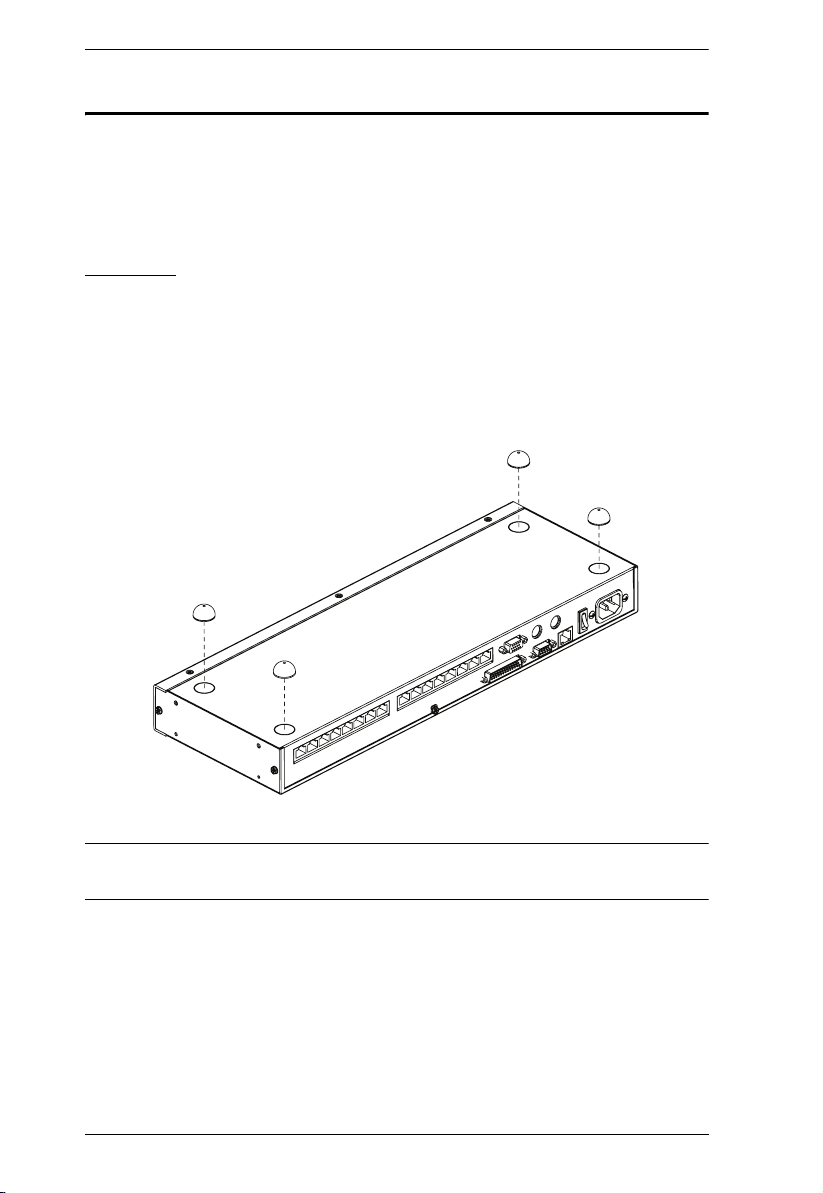
Stacking
The KH1508i / KH1516i can be placed on any appropriate level surface that
can safely support its weight plus the weight of its attached cables. To place the
KH1508i / KH1516i, or to stack units if you are daisy chaining them, remove
the backing material from the bottom of the rubber feet that came with this
package, and stick them onto the switch’s bottom panel at the corners, as
shown in the diagram, below:
Note: To ensure adequate ventilation, allow at least 5.1 cm on each side, and
12.7cm at the back for power cord and cable clearance.
10
Chapter 2. Hardware Setup
x
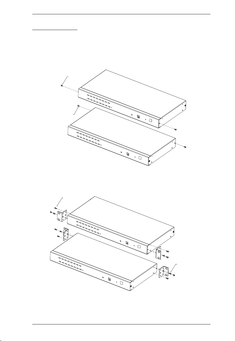
Rack Mounting
The KH1508i / KH1516i can be mounted in a 19" (1U) racks. The mounting
brackets can screw into either the front or the back of the unit so that it can
attach to the front or the back of the rack. To rack mount the unit:
1. Remove the screws at the front or the rear, as shown in the diagram below.
Phillips head hex
M3 x 6
Phillips head hex
M3 x 6
2. Screw the mounting brackets into the sides of the unit at the front or the
rear, as shown in the diagram below.
Phillips head hex
M3 x 8
Phillips head he
M3 x 8
3. Slide the unit into the front or rear of the rack and secure it to the rack.
11

KH1508i / KH1516i User Manual
Single Station Installation
In a Single Stage installation, there are no additional KVM switches daisy
chained down from the KH1508i / KH1516i. To set up a single stage
installation, refer to the installation diagrams starting on page 13 (the numbers
in the diagram correspond with the numbers of the instruction steps), and do
the following:
1. Plug your Local Console’s keyboard, monitor, and mouse into the unit’s
Console Ports. Each port is color coded and marked with an appropriate
icon to identify itself.
Note: The KH1508i / KH1516i does not support distances that exceed
20m between itself and the local monitor.
2. Use Cat. 5 cable to connect any available KVM port to a KVM Adapter
Cable that is appropriate for the computer you are installing (see KVM
Adapter Cables, page 5 for details).
Note: The KH1508i / KH1516i does not support distances that exceed
40m between itself and the KVM Adapter Cable.
3. Connect the KVM Adapter Cable to the computer.
Plug the connectors on the KVM Adapter Cable into the appropriate ports
of the computer you are installing. (See KVM Adapter Cable Installation
Diagrams, page 14 for connection examples.)
4. Plug the LAN or WAN cable into the KH1508i / KH1516i’s LAN port.
5. Plug the female end of the power cord into the KH1508i / KH1516i's
Power Socket; plug the male end into an AC power source.
6. Turn on the power to the KH1508i / KH1516i.
After the KH1508i / KH1516i is powered up, you can turn on the computers.
12
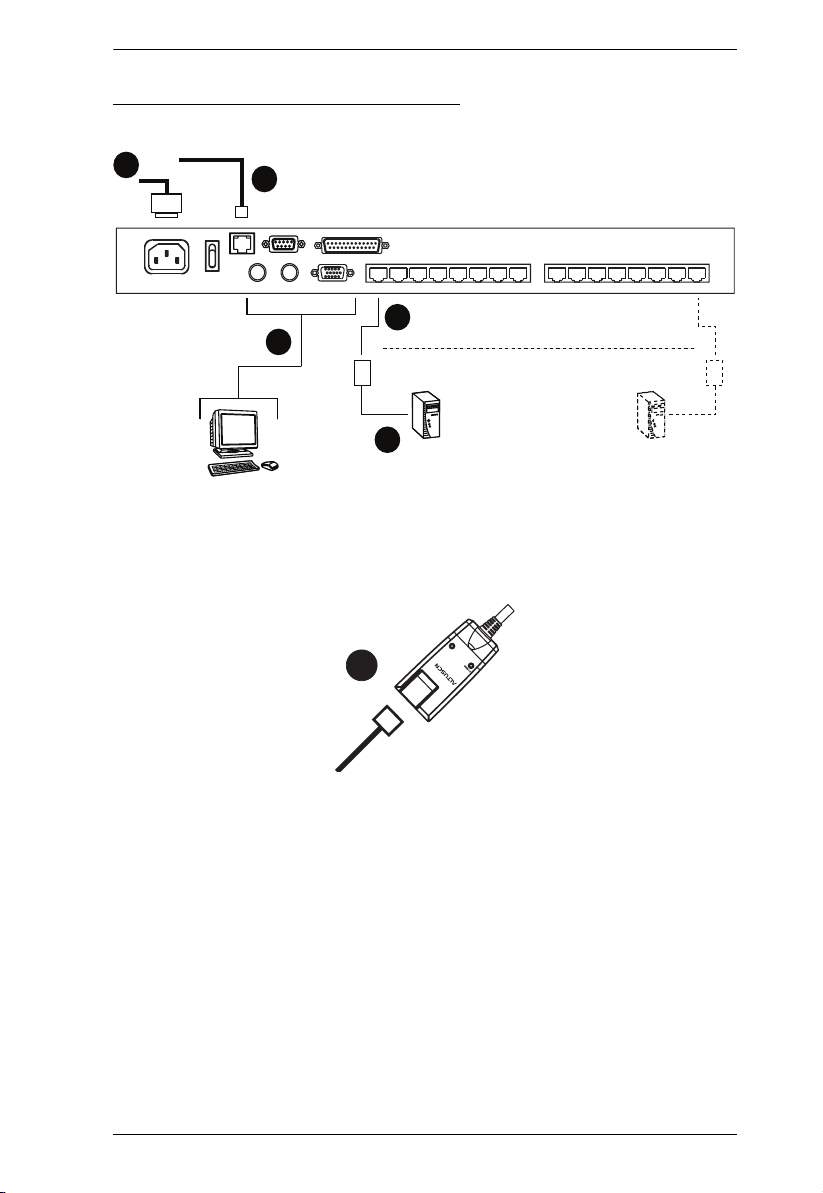
Single Stage Installation Diagram
Chapter 2. Hardware Setup
5
4
2
1
3
K
LIN
TEN
y A
b
E
E
NO. KA9120
2
NO. KA9120
MODEL
MODEL
PS/2 CPU MODUL
PS/2 CPU MODUL
13
KH1508i / KH1516i User Manual
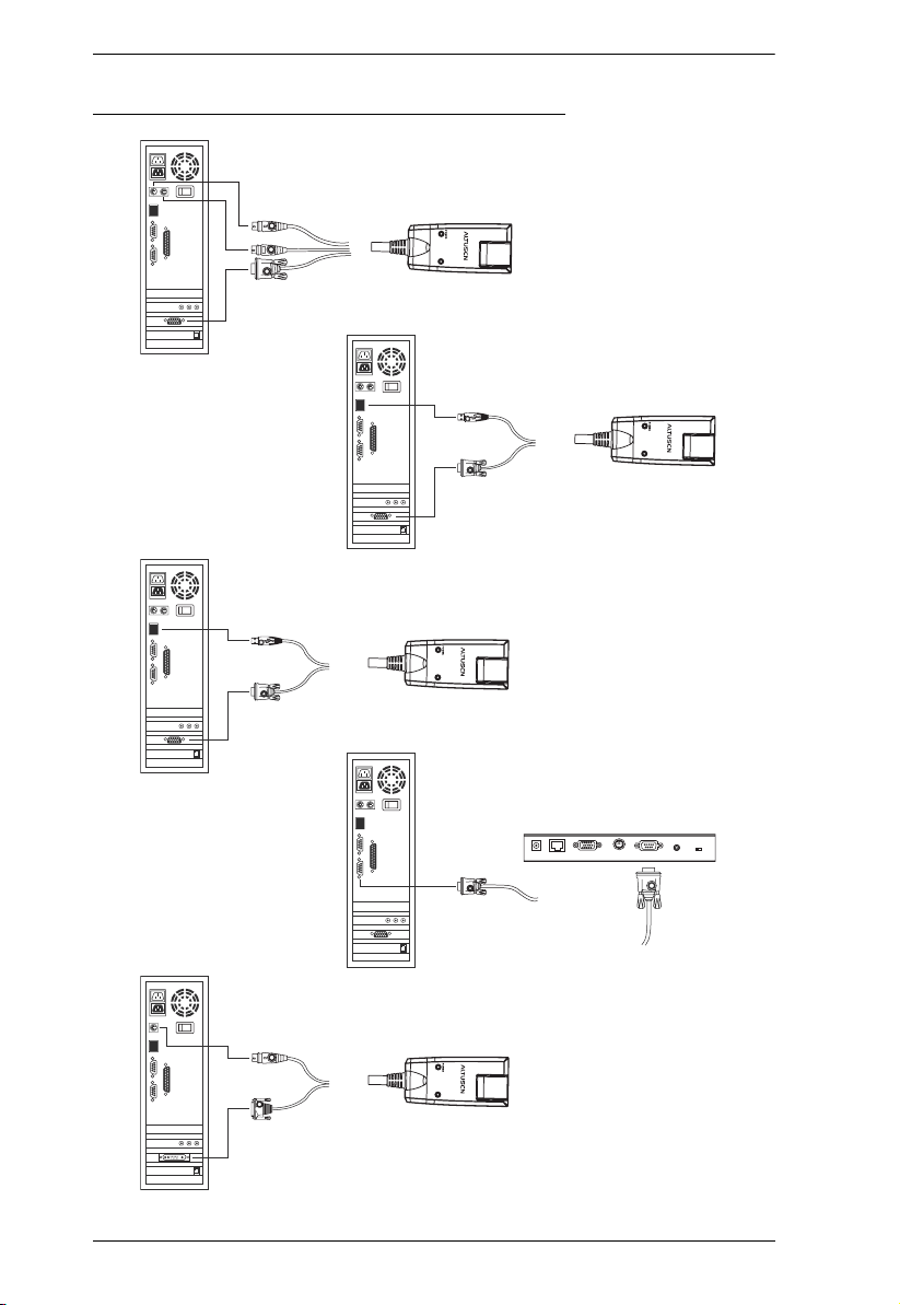
KVM Adapter Cable Installation Diagrams
KA9520
LIN
b
y A
K
TEN
KA9570
LIN
by A
K
TEN
KA9131
LIN
b
y A
K
TEN
14
KA9140
SERIAL TERMINAL
KA9130
LIN
b
y A
K
TEN

Chapter 2. Hardware Setup
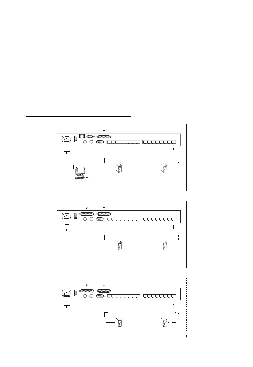
Daisy Chaining
Up to 15 additional KH1508 / KH1516 KVM switches can be daisy chained
down from the KH1508i or KH1516i. As many as 256 computers can be
controlled from a single console in a complete installation.
Note: Aten ACS1208 / ACS1216 switches can also be installed on a KH1508i
/ KH1516i daisy chain.
To set up a daisy chained installation, do the following:
1. Use a daisy chain cable set to connect the Chain Out port of the parent unit
to the Chain In port of the child unit (First Station Out to Second Station
In, Second Station Out to Third Station In, etc.).
Note: 1. The KH1508i / KH1516i doesn’t have a Chain In port since it is
the highest level parent – it only has a Chain Out port.
2. Daisy chain cable sets require a separate purchase – see your
dealer for details.
3. The KH1508i / KH1516i does not support distances that exceed
100m between the first station and the last station.
2. Use Cat. 5 cable to connect any available KVM port to a KVM Adapter
Cable that is appropriate for the computer you are installing (see KVM
Adapter Cables, page 5 for details).
Note: The switches do not support distances that exceed 40 m between
themselves and the KVM Adapter Cable.
3. Connect the KVM Adapter Cable to the computer. Refer to the installation
diagram on the previous page for details.
4. Use the power cord supplied with this package to connect the KVM switch
to an AC power source.
5. Repeat steps 1–4 for any other switches you want to add to the chain.
15
KH1508i / KH1516i User Manual
6. Power up the installation according to the following procedure:
a) Power up the First Station. Wait for the unit to ascertain its Station ID
and display it on the Station ID LED. (The Station ID for the First Stage
unit is 01, the ID for the Second Stage unit is 02, the ID for the Third
Stage unit is 03, etc.)
b) Power on each station in turn (Second Station, then Third Station, etc.).
In each case, wait for the Station ID to be ascertained and displayed
before powering on the next station.
c) After all the Stations are up, power on the computers.
Daisy Chain Installation Diagram
KH1516i
16
KH1516
KH1516

Chapter 3
Basic Operation
Port Selection
KH1508i / KH1516i installations provide three methods to obtain instant
access to any computer in your installation: Manual, OSD, and Hotkey.
Manual
For manual port selection, simply press the Port Switch that corresponds to the
device you wish to access.
OSD
OSD (On Screen Display), provides a menu driven interface to the computer
switching procedure. The KH1508i / KH1516i provides two OSD systems: A
text-based OSD when you log in from a local console; and a graphical OSD
when you log in remotely over the internet. Local console OSD operation is
discussed in the next chapter; graphical OSD operation is discussed in
Chapter 7 (for Windows logins) and Chapter 8 (for Java logins).
Keyboard Hotkeys
Hotkeys allow you to conveniently provide KVM focus to a particular
computer from the local console keyboard, instead of having to manually select
them by pressing Port Selection switches. See Keyboard Port Operation,
page 34, for details.
17

KH1508i / KH1516i User Manual
Hot Plugging
The KH1508i / KH1516i supports hot plugging – components can be removed
and added back into the installation by unplugging and replugging their cables
from their ports without the need to shut the unit down. In order for hot
plugging to work properly, however, the procedures described below must be
followed.
Hot Plugging Stations
You can switch station positions by simply unplugging from the old parent and
plugging into a new one. After you do, in order for the OSD menus to
correspond to the change, you must reset the OSD. See RESET STATION IDS,
page 29, for details.
Hot Plugging KVM Ports
After switching KVM ports, in order for the OSD menus to correspond to the
change, you must manually reconfigure the OSD information for the new Port
information. See F3 SET, page 26, and the Port Setting selections under the F4
ADM function, page 29, for details.
Note: If the computer’s Operating System doesn’t support hot plugging, this
function may not work properly.
Hot Plugging Console Ports:
Keyboard, monitor, and mouse can all be hot plugged. When hot plugging
the mouse:
You may unplug the mouse and plug it back in again (to reset the mouse,
for example), as long as you use the same mouse.
If you plug in a different mouse, all the stations and all the computers on
the installation must be shut down for 10 seconds, then restarted following
the Power Up Sequence described under Step 6 on page 16.)
Note: If, after hot plugging (or at any other time), there is no response to
keyboard and/or mouse input, perform a Keyboard and Mouse Reset
by pressing in the Reset switch (see page 7).
18
 Loading...