

ATEN KH1508A, KH1516A, KH1532A User Manual
KVM Switch
KH1508A / KH1516A / KH1532A
User Manual
www.aten.com

KH1508A / KH1516A / KH1532A User Manual
EMC Information
FEDERAL COMMUNICATIONS COMMISSION INTERFERENCE
STATEMENT: This equipment has been tested and found to comply with the
limits for a Class A digital device, pursuant to Part 15 of the FCC Rules. These
limits are designed to provide reasonable protection against harmful
interference when the equipment is operated in a commercial environment.
This equipment generates, uses, and can radiate radio frequency energy and, if
not installed and used in accordance with the instruction manual, may cause
harmful interference to radio communications. Operation of this equipment in
a residential area is likely to cause harmful interference in which case the user
will be required to correct the interference at his own expense.
The device complies with Part 15 of the FCC Rules. Operation is subject to the
following two conditions: (1) this device may not cause harmful interference,
and (2) this device must accept any interference received, including
interference that may cause undesired operation.
FCC Caution: Any changes or modifications not expressly approved by the
party responsible for compliance could void the user's authority to operate this
equipment.
Warning: Operation of this equipment in a residential environment could
cause radio interference.
Achtung: Der Gebrauch dieses Geräts in Wohnumgebung kann
Funkstörungen verursachen.
Suggestion: Shielded twisted pair (STP) cables must be used with the unit to
ensure compliance with FCC & CE standards.
KCC Statement
RoHS
This product is RoHS compliant.
ii
KH1508A / KH1516A / KH1532A User Manual
User Information
Online Registration
Be sure to register your product at our online support center:
International http://eservice.aten.com
Telephone Support
For telephone support, call this number:
International 886-2-8692-6959
China 86-400-810-0-810
Japan 81-3-5615-5811
Korea 82-2-467-6789
North America 1-888-999-ATEN ext 4988
1-949-428-1111
User Notice
All information, documentation, and specifications contained in this manual
are subject to change without prior notification by the manufacturer. The
manufacturer makes no representations or warranties, either expressed or
implied, with respect to the contents hereof and specifically disclaims any
warranties as to merchantability or fitness for any particular purpose. Any of
the manufacturer's software described in this manual is sold or licensed as is.
Should the programs prove defective following their purchase, the buyer (and
not the manufacturer, its distributor, or its dealer), assumes the entire cost of all
necessary servicing, repair and any incidental or consequential damages
resulting from any defect in the software.
The manufacturer of this system is not responsible for any radio and/or TV
interference caused by unauthorized modifications to this device. It is the
responsibility of the user to correct such interference.
The manufacturer is not responsible for any damage incurred in the operation
of this system if the correct operational voltage setting was not selected prior
to operation. PLEASE VERIFY THAT THE VOLTAGE SETTING IS
CORRECT BEFORE USE.
iii

KH1508A / KH1516A / KH1532A User Manual
Copyright © 2020 ATEN® International Co., Ltd.
Manual Date: 2020-11-26
Altusen and the Altusen logo are registered trademarks of ATEN International Co., Ltd. All rights reserved.
All other brand names and trademarks are the registered property of their respective owners.
Package Contents
The KH1508A / KH1516A / KH1532A package consists of:
1 KH1508A, KH1516A, or KH1532A Cat 5 High-Density KVM Switch
1 Firmware Upgrade Cable
1Power Cord
1 Mounting Kit
1 Foot Pad Set (4 pcs.)
1 User Instructions*
Check to make sure that all of the components are present and in good order.
If anything is missing, or was damaged in shipping, contact your dealer.
Read this manual thoroughly and follow the installation and operation
procedures carefully to prevent any damage to the switch or to any other
devices on the KH1508A / KH1516A / KH1532A installation.
* Features may have been added to the KH1508A / KH1516A / KH1532A
since this manual was published. Please visit our web site to download the
most up-to-date version of the manual.
iv

KH1508A / KH1516A / KH1532A User Manual
Contents
EMC Information . . . . . . . . . . . . . . . . . . . . . . . . . . . . . . . . . . . . . . . . . . . . ii
RoHS. . . . . . . . . . . . . . . . . . . . . . . . . . . . . . . . . . . . . . . . . . . . . . . . . . . . . . ii
User Information . . . . . . . . . . . . . . . . . . . . . . . . . . . . . . . . . . . . . . . . . . . . .iii
Online Registration . . . . . . . . . . . . . . . . . . . . . . . . . . . . . . . . . . . . . . . .iii
Telephone Support . . . . . . . . . . . . . . . . . . . . . . . . . . . . . . . . . . . . . . . .iii
User Notice . . . . . . . . . . . . . . . . . . . . . . . . . . . . . . . . . . . . . . . . . . . . . .iii
Package Contents . . . . . . . . . . . . . . . . . . . . . . . . . . . . . . . . . . . . . . . . . . iv
Contents . . . . . . . . . . . . . . . . . . . . . . . . . . . . . . . . . . . . . . . . . . . . . . . . . . . v
About This Manual . . . . . . . . . . . . . . . . . . . . . . . . . . . . . . . . . . . . . . . . . .viii
Overview . . . . . . . . . . . . . . . . . . . . . . . . . . . . . . . . . . . . . . . . . . . . . . .viii
Conventions . . . . . . . . . . . . . . . . . . . . . . . . . . . . . . . . . . . . . . . . . . . . . . . ix
Product Information. . . . . . . . . . . . . . . . . . . . . . . . . . . . . . . . . . . . . . . . . . ix
Chapter 1.
Overview . . . . . . . . . . . . . . . . . . . . . . . . . . . . . . . . . . . . . . . . . . . . . . . . . . . 1
Features and Benefits . . . . . . . . . . . . . . . . . . . . . . . . . . . . . . . . . . . . . . . .2
Requirements . . . . . . . . . . . . . . . . . . . . . . . . . . . . . . . . . . . . . . . . . . . . . . .4
Components . . . . . . . . . . . . . . . . . . . . . . . . . . . . . . . . . . . . . . . . . . . . . . . .6
Chapter 2.
Overview . . . . . . . . . . . . . . . . . . . . . . . . . . . . . . . . . . . . . . . . . . . . . . . . . . 11
Before you Begin. . . . . . . . . . . . . . . . . . . . . . . . . . . . . . . . . . . . . . . . . . . .11
Stacking and Rack Mounting . . . . . . . . . . . . . . . . . . . . . . . . . . . . . . . . . . 12
Single Station Installation . . . . . . . . . . . . . . . . . . . . . . . . . . . . . . . . . . . . .14
Daisy Chaining . . . . . . . . . . . . . . . . . . . . . . . . . . . . . . . . . . . . . . . . . . . . . 18
Introduction
Console . . . . . . . . . . . . . . . . . . . . . . . . . . . . . . . . . . . . . . . . . . . . . . . . 4
Computers . . . . . . . . . . . . . . . . . . . . . . . . . . . . . . . . . . . . . . . . . . . . . . 4
KVM Adapter Cables . . . . . . . . . . . . . . . . . . . . . . . . . . . . . . . . . . . . . .5
Operating Systems . . . . . . . . . . . . . . . . . . . . . . . . . . . . . . . . . . . . . . . .5
Front View . . . . . . . . . . . . . . . . . . . . . . . . . . . . . . . . . . . . . . . . . . . . . .6
KH1508A . . . . . . . . . . . . . . . . . . . . . . . . . . . . . . . . . . . . . . . . . . . .6
KH1516A . . . . . . . . . . . . . . . . . . . . . . . . . . . . . . . . . . . . . . . . . . . . .6
KH1532A . . . . . . . . . . . . . . . . . . . . . . . . . . . . . . . . . . . . . . . . . . . .6
Rear View . . . . . . . . . . . . . . . . . . . . . . . . . . . . . . . . . . . . . . . . . . . . . . .8
KH1508A . . . . . . . . . . . . . . . . . . . . . . . . . . . . . . . . . . . . . . . . . . . .8
KH1516A . . . . . . . . . . . . . . . . . . . . . . . . . . . . . . . . . . . . . . . . . . . . .8
KH1532A . . . . . . . . . . . . . . . . . . . . . . . . . . . . . . . . . . . . . . . . . . . . .8
Hardware Setup
Stacking. . . . . . . . . . . . . . . . . . . . . . . . . . . . . . . . . . . . . . . . . . . . . . . .12
Rack Mounting . . . . . . . . . . . . . . . . . . . . . . . . . . . . . . . . . . . . . . . . . .13
Chapter 3.
Port Selection . . . . . . . . . . . . . . . . . . . . . . . . . . . . . . . . . . . . . . . . . . . . . .21
Basic Operation
Manual. . . . . . . . . . . . . . . . . . . . . . . . . . . . . . . . . . . . . . . . . . . . . . . . .21
OSD. . . . . . . . . . . . . . . . . . . . . . . . . . . . . . . . . . . . . . . . . . . . . . . . . . .21
Hotkey . . . . . . . . . . . . . . . . . . . . . . . . . . . . . . . . . . . . . . . . . . . . . . . . . 21
v

KH1508A / KH1516A / KH1532A User Manual
Hot Plugging . . . . . . . . . . . . . . . . . . . . . . . . . . . . . . . . . . . . . . . . . . . . . . 22
Hot Plugging Stations . . . . . . . . . . . . . . . . . . . . . . . . . . . . . . . . . . . . . 22
Hot Plugging KVM Ports . . . . . . . . . . . . . . . . . . . . . . . . . . . . . . . . . . . 22
Hot Plugging Console Ports . . . . . . . . . . . . . . . . . . . . . . . . . . . . . . . . 22
Powering Off and Restarting . . . . . . . . . . . . . . . . . . . . . . . . . . . . . . . . . . 24
Port ID Numbering . . . . . . . . . . . . . . . . . . . . . . . . . . . . . . . . . . . . . . . . . . 24
Chapter 4.
OSD Overview . . . . . . . . . . . . . . . . . . . . . . . . . . . . . . . . . . . . . . . . . . . . . 25
OSD Navigation . . . . . . . . . . . . . . . . . . . . . . . . . . . . . . . . . . . . . . . . . . . . 27
OSD Main Screen Headings. . . . . . . . . . . . . . . . . . . . . . . . . . . . . . . . . . . 27
OSD Functions . . . . . . . . . . . . . . . . . . . . . . . . . . . . . . . . . . . . . . . . . . . . 28
Chapter 5.
Hotkey Port Control . . . . . . . . . . . . . . . . . . . . . . . . . . . . . . . . . . . . . . . . . 41
Invoking Hotkey Mode . . . . . . . . . . . . . . . . . . . . . . . . . . . . . . . . . . . . . . . 42
Selecting the Active Port . . . . . . . . . . . . . . . . . . . . . . . . . . . . . . . . . . . . . 43
Auto Scan Mode Switching . . . . . . . . . . . . . . . . . . . . . . . . . . . . . . . . . . . 44
Skip Mode Switching . . . . . . . . . . . . . . . . . . . . . . . . . . . . . . . . . . . . . . . . 46
Computer Keyboard / Mouse Reset . . . . . . . . . . . . . . . . . . . . . . . . . . . . 47
Setting the Hotkey Beeper ON/OFF . . . . . . . . . . . . . . . . . . . . . . . . . . . . . 47
Setting the Hotkey key combination . . . . . . . . . . . . . . . . . . . . . . . . . . . . 48
Setting the OSD Hotkey combination . . . . . . . . . . . . . . . . . . . . . . . . . . . . 48
Setting the Port Operating System . . . . . . . . . . . . . . . . . . . . . . . . . . . . . 49
Restore the Default Values. . . . . . . . . . . . . . . . . . . . . . . . . . . . . . . . . . . . 49
Hotkey Summary Table . . . . . . . . . . . . . . . . . . . . . . . . . . . . . . . . . . . . . . 50
OSD Operation
F1: GOTO . . . . . . . . . . . . . . . . . . . . . . . . . . . . . . . . . . . . . . . . . . . . . 28
F2: LIST . . . . . . . . . . . . . . . . . . . . . . . . . . . . . . . . . . . . . . . . . . . . . . . 29
F3: SET . . . . . . . . . . . . . . . . . . . . . . . . . . . . . . . . . . . . . . . . . . . . . . . 30
F4: ADM . . . . . . . . . . . . . . . . . . . . . . . . . . . . . . . . . . . . . . . . . . . . . . . 33
F5: SKP . . . . . . . . . . . . . . . . . . . . . . . . . . . . . . . . . . . . . . . . . . . . . . . 36
F6: BRC . . . . . . . . . . . . . . . . . . . . . . . . . . . . . . . . . . . . . . . . . . . . . . . 37
F7: SCAN . . . . . . . . . . . . . . . . . . . . . . . . . . . . . . . . . . . . . . . . . . . . . . 38
F8: LOUT . . . . . . . . . . . . . . . . . . . . . . . . . . . . . . . . . . . . . . . . . . . . . . 39
Hotkey Operation
Number Lock and Minus Keys . . . . . . . . . . . . . . . . . . . . . . . . . . . 42
Control and F12 Keys . . . . . . . . . . . . . . . . . . . . . . . . . . . . . . . . . . 42
Hotkey Mode Environment . . . . . . . . . . . . . . . . . . . . . . . . . . . . . . 42
Exiting Hotkey Mode . . . . . . . . . . . . . . . . . . . . . . . . . . . . . . . . . . . 42
Setting the Scan Interval . . . . . . . . . . . . . . . . . . . . . . . . . . . . . . . . 44
Invoking Auto Scan . . . . . . . . . . . . . . . . . . . . . . . . . . . . . . . . . . . . 44
Exiting Auto Scan . . . . . . . . . . . . . . . . . . . . . . . . . . . . . . . . . . . . . 45
Entering Skip Mode. . . . . . . . . . . . . . . . . . . . . . . . . . . . . . . . . . . . 46
Exiting Skip Mode . . . . . . . . . . . . . . . . . . . . . . . . . . . . . . . . . . . . . 46
Chapter 6.
Mac Keyboard. . . . . . . . . . . . . . . . . . . . . . . . . . . . . . . . . . . . . . . . . . . . . . 51
Sun Keyboard . . . . . . . . . . . . . . . . . . . . . . . . . . . . . . . . . . . . . . . . . . . . . 52
vi
Keyboard Emulation

KH1508A / KH1516A / KH1532A User Manual
Chapter 7.
Introduction . . . . . . . . . . . . . . . . . . . . . . . . . . . . . . . . . . . . . . . . . . . . . . . . 53
The Firmware Upgrade Utility
Before You Begin . . . . . . . . . . . . . . . . . . . . . . . . . . . . . . . . . . . . . . . . 54
Performing the Upgrade . . . . . . . . . . . . . . . . . . . . . . . . . . . . . . . . . . . 56
Starting the Upgrade . . . . . . . . . . . . . . . . . . . . . . . . . . . . . . . . . . .56
Upgrade Succeeded . . . . . . . . . . . . . . . . . . . . . . . . . . . . . . . . . . .59
Upgrade Failed . . . . . . . . . . . . . . . . . . . . . . . . . . . . . . . . . . . . . . .60
Firmware Upgrade Recovery . . . . . . . . . . . . . . . . . . . . . . . . . . . . . . . 60
Main Board Firmware Upgrade Recovery . . . . . . . . . . . . . . . . . . . 60
Adapter Cable Firmware Upgrade Recovery. . . . . . . . . . . . . . . . . 61
Appendix
Safety Instructions. . . . . . . . . . . . . . . . . . . . . . . . . . . . . . . . . . . . . . . . . . .63
General . . . . . . . . . . . . . . . . . . . . . . . . . . . . . . . . . . . . . . . . . . . . . . . .63
Rack Mounting . . . . . . . . . . . . . . . . . . . . . . . . . . . . . . . . . . . . . . . . . .65
Consignes de sécurité . . . . . . . . . . . . . . . . . . . . . . . . . . . . . . . . . . . . . . .66
Général . . . . . . . . . . . . . . . . . . . . . . . . . . . . . . . . . . . . . . . . . . . . . . . .66
Montage sur bâti . . . . . . . . . . . . . . . . . . . . . . . . . . . . . . . . . . . . . . . . .69
Technical Support . . . . . . . . . . . . . . . . . . . . . . . . . . . . . . . . . . . . . . . . . .70
International. . . . . . . . . . . . . . . . . . . . . . . . . . . . . . . . . . . . . . . . . . . . .70
North America . . . . . . . . . . . . . . . . . . . . . . . . . . . . . . . . . . . . . . . . . . .70
Specifications . . . . . . . . . . . . . . . . . . . . . . . . . . . . . . . . . . . . . . . . . . . . . . 71
Connection Tables . . . . . . . . . . . . . . . . . . . . . . . . . . . . . . . . . . . . . . . . . .73
KH1508A . . . . . . . . . . . . . . . . . . . . . . . . . . . . . . . . . . . . . . . . . . . . . . .73
KH1516A . . . . . . . . . . . . . . . . . . . . . . . . . . . . . . . . . . . . . . . . . . . . . . .73
KH1532A . . . . . . . . . . . . . . . . . . . . . . . . . . . . . . . . . . . . . . . . . . . . . . .73
Compatible Products . . . . . . . . . . . . . . . . . . . . . . . . . . . . . . . . . . . . . . . .74
OSD Factory Default Settings . . . . . . . . . . . . . . . . . . . . . . . . . . . . . . . . .75
Administrator Login Failure . . . . . . . . . . . . . . . . . . . . . . . . . . . . . . . . . . .76
Troubleshooting . . . . . . . . . . . . . . . . . . . . . . . . . . . . . . . . . . . . . . . . . . . . 77
Overview . . . . . . . . . . . . . . . . . . . . . . . . . . . . . . . . . . . . . . . . . . . . . . .77
Limited Warranty. . . . . . . . . . . . . . . . . . . . . . . . . . . . . . . . . . . . . . . . . . . .78
vii

KH1508A / KH1516A / KH1532A User Manual
About This Manual
This User Manual is provided to help you get the most from your KH1508A /
KH1516A / KH1532A system. It covers all aspects of installation,
configuration and operation. An overview of the information found in the
manual is provided below.
Overview
Chapter 1, Introduction, introduces you to the KH1508A / KH1516A /
KH1532A system. Its purpose, features and benefits are presented, and its front
and back panel components are described.
Chapter 2, Hardware Setup, describes how to set up your installation. The
necessary steps – from a basic single stage hookup to a complete daisy chained
operation are provided.
Chapter 3, Basic Operation, explains the fundamental concepts involved
in operating the KH1508A / KH1516A / KH1532A.
Chapter 4, OSD Operation, provides a complete description of the
KH1508A / KH1516A / KH1532A's OSD (On Screen Display), and how to
work with it.
Chapter 5, Hotkey Operation, details all of the concepts and procedures
involved in the keyboard hotkey operation of your KH1508A / KH1516A /
KH1532A installation.
Chapter 6, Keyboard Emulation, provides tables that list the PC to Mac
and PC to Sun keyboard emulation mappings.
Chapter 7, The Firmware Upgrade Utility, explains how to upgrade the
KH1508A / KH1516A / KH1532A's firmware with the latest available
versions.
An Appendix, provides specifications and other technical information
regarding the KH1508A / KH1516A / KH1532A.
viii
KH1508A / KH1516A / KH1532A User Manual
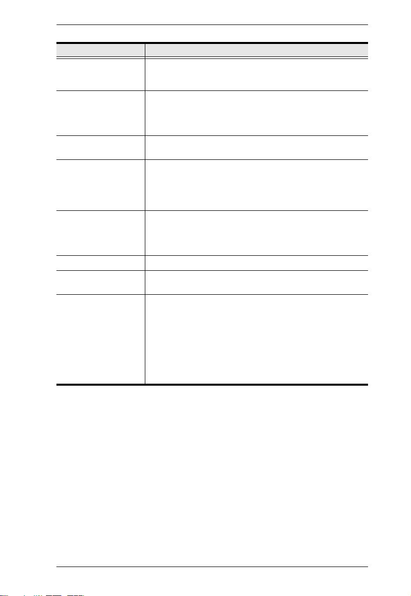
Conventions
This manual uses the following conventions:
Monospaced Indicates text that you should key in.
[ ] Indicates keys you should press. For example, [Enter]
means to press the Enter key. If keys need to be chorded,
they appear together in the same bracket with a plus sign
between them: [Ctrl+Alt].
1. Numbered lists represent procedures with sequential steps.
♦ Bullet lists provide information, but do not involve sequential
steps.
→ Indicates selecting the option (on a menu or dialog box, for
example), that comes next. For example, Start → Run means
to open the Start menu, and then select Run.
Indicates critical information.
Product Information
For information about all ALTUSEN products and how they can help you
connect without limits, visit ALTUSEN on the Web or contact an ALTUSEN
Authorized Reseller. Visit ALTUSEN on the Web for a list of locations and
telephone numbers:
International http://www.aten.com
North America http://www.aten-usa.com
ix

KH1508A / KH1516A / KH1532A User Manual
This Page Intentionally Left Blank
x

Chapter 1
Introduction
Overview
A KH1508A / KH1516A / KH1532A KVM switch is a control unit that allows
IT administrators to access and control multiple computers from a single PS/2
or USB KVM (keyboard, monitor, and mouse) console. A single KH1508A /
KH1516A / KH1532A KVM switch can control up to 8 / 16 / 32 computers.
By daisy chaining up to 31 additional switches, as many as 1024 computers can
be controlled from the original KVM console. An auto-sensing function
recognizes the position of each station on the chain, eliminating the need to
manually set the position, and a seven-segment front panel LED displays each
station's position for easy identification.
Compact, high-density, RJ-45 connectors and CAT 5e/6 cable make for a
compact, efficient, wiring configuration, while the use of PS/2 and USB KVM
Adapter Cables to link to the computers, permits any combination of PCs,
Macs, Sun computers, and serial devices to coexist on the installation.
Setting up the KH1508A / KH1516A / KH1532A is fast and easy – plugging
cables into their appropriate ports is all that is entailed. Because the KH1508A
/ KH1516A / KH1532A intercepts keyboard and mouse input directly, there is
no software to configure and no complex installation routines.
Access to any computer on the installation is easily accomplished – either by
pressing front panel port selection pushbuttons; entering hotkey combinations
from the keyboard; or by means of a powerful OSD (On Screen Display) menu
system. A convenient Auto Scan function also permits automatic scanning and
one-by-one monitoring of the activities of selected computers.
Your KH1508A / KH1516A / KH1532A investment is protected through
firmware upgrades. You can download firmware update files from our website,
and use the Firmware Upgrade function to quickly and conveniently install
them.
There is no better way to save time and money than with a KH1508A /
KH1516A / KH1532A installation. By allowing a single console to manage up
to 1024 computers, you: (1) eliminate the expense of purchasing separate
keyboards, monitors, and mice; (2) save space; (3) save on energy costs; and
(4) eliminate the inconvenience and wasted effort involved in constantly
having to move from one computer to another.
1

KH1508A / KH1516A / KH1532A User Manual
Features and Benefits
The features and benefits provided by a KH1508A / KH1516A / KH1532A
deployment are described in the following table:
Features Benefits
Simple Installation and
Operation
Single Console Control Access and control up to 8 (KH1508A) or 16 (KH1516A) or 32
Scalability By daisy chaining up to 31 additional KH1508A / KH1516A /
Easy Installation Setting up the KH1508A / KH1516A / KH1532A is fast and
Easy Operation Three port selection methods: Manual (via front panel
Hardware Independent
Cross-Platform
Support
Space-Saving RJ-45
Connectors and Cat
5e/6 Cabling
KVM Adapter Cables
to Connect to Servers
and Devices
Plug-and-play installation – no software required – connecting
cables is all it takes. Station positions are automatically
recognized. Computer selection via front panel switches;
hotkeys; or multi-language OSD (On Screen Display) menus.
(KH1532A) computers from a single PS/2 or USB KVM
(keyboard, monitor, and mouse) console.
KH1532A switches*, as many as up to 1024 computers can
be controlled from the original KVM console – eliminating the
expense of purchasing separate peripherals for each server.
Note: If you wish to include KH1532A into your daisy chain,
you must have a KH1532A as the master switch.
easy – plugging cables into their appropriate ports is all that is
entailed. Because there is no software to configure,
incompatibility and configuration issues are non-existent.
pushbuttons), Hotkey, and multi-language OSD (On Screen
Display).
Multi-language keyboard support includes English (US / UK),
French, German, Japanese, Korean, and Traditional Chinese.
The KH1508A / KH1516A / KH1532A supports Windows
2000/XP/Vista/7, Linux, Unix, Novell, FreeBSD, Sun, and
Mac.
This space-saving innovation means that the KH1508A /
KH1516A / KH1532A can be conveniently installed in a 1U
system rack, and the installation can take advantage of the
internal network wiring built into most modern commercial
buildings.
Reduces cable clutter for a neat and tidy data center
environment.
For convenience and flexibility that allows mixing the PS/2,
USB and serial interfaces, the KH1508A / KH1516A /
KH1532A's design utilizes KVM adapter cables that serve as
intermediaries between the KVM switch and the connected
devices.
KVM adapter cables are available in PS/2, USB, and Serial
interfaces to support a wide variety of data center servers and
devices.
2
Chapter 1. Introduction
Features Benefits
Two-Level Password
Security
Supports one administrator and ten user profiles. Strong
password protection prevents unauthorized access to the
installation – keeping your valuable data secure.
Upgradeable Firmware Stay current with the latest functionality improvements and
updates by downloading firmware upgrade files from our
website and installing them with the built-in firmware upgrade
utility.
Effortless Upgrades Simultaneous firmware upgrades to all daisy-chained KVM
switches and dongles through the daisy-chain cable.
Auto Scanning and
Broadcast Mode
Auto scanning provides hands-free monitoring of selected
devices at variable rates. Broadcast Mode sends commands
from the console to all computers – allowing you to perform
operations (such as software installation, upgrades,
shutdowns, etc.), on them simultaneously.
Superior Video Quality Supports video resolutions up to 1920 x 1200 @ 60 Hz up to
30 meters, 1600 x 1200 @ 60 Hz up to 40 meters, and 1280 x
1024 @ 75 Hz up to 50 meters.*
*With the KVM adapter cable KA7000 series.
Multiple User Accounts Supports up to 10 user and 1 administrator accounts
Hot Pluggable Ability to add or remove components without having to power
off the KVM switch.
Adapter Cables with ID The KH1508A / KH1516A / KH1532A KVM series supports
automatic ID recognition of the new ATEN KVM Cable
Adapter KA7000 series ( KVM Adapter Cables). Using the
new adapter cables with ID means it is not required to change
cable configuration settings when moving cables from port to
port.
Device ID and attributes are stored in the adapter cables
allowing you to hot-swap port connections without having to
reconfigure attributes.
3

KH1508A / KH1516A / KH1532A User Manual
Requirements
Console
A VGA, SVGA, or multisync monitor capable of the highest resolution
that you will be using on any computer in the installation
A PS/2 or USB mouse
A PS/2 or USB keyboard
Computers
The following equipment must be installed on the computers that connect to the
KH1508A / KH1516A / KH1532A KVM ports:
A VGA, SVGA or multisync port
A Type A USB port and USB host controller (for USB KVM adapter cable
connection, see following section)
- or -
6-pin Mini-DIN keyboard and mouse ports (for PS/2 KVM adapter cable
connection, see following section)
4
Chapter 1. Introduction
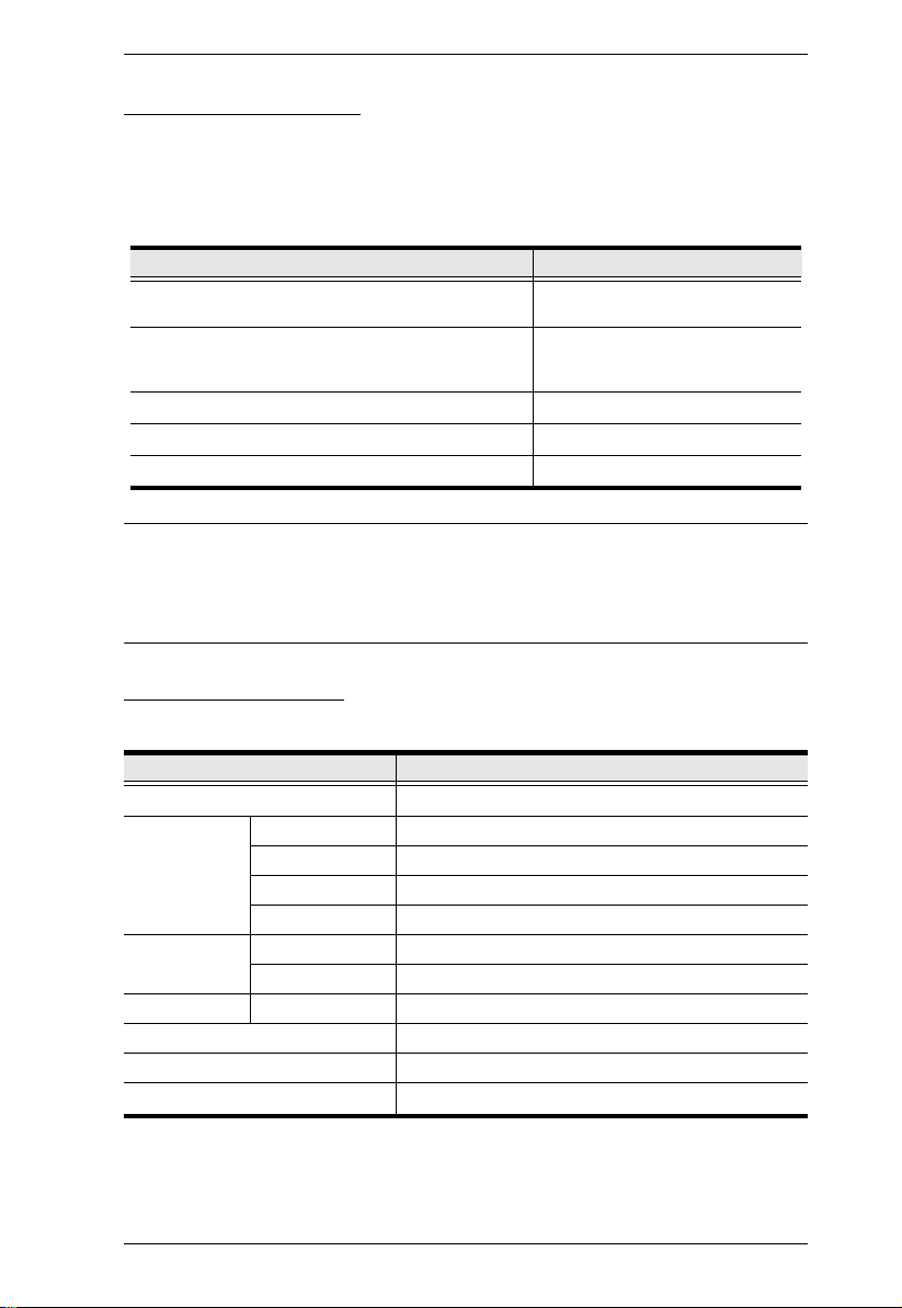
KVM Adapter Cables
Cat 5e/6 cable is required to connect the KH1508A / KH1516A / KH1532A to
one of the KVM adapter cables.
The following KVM adapter cables are required for use with the KH1508A /
KH1516A / KH1532A:
Function Module
Connect to devices with PS/2 ports KA7920 / KA7520 / KA7120
Connect to devices with USB ports KA7166 / KA7168 / KA7169 /
Connect to Sun Legacy systems (with 13W3 port) KA9130 / KA7130
Connect to Sun USB systems KA9170 / KA7170
Connect to serial based devices KA9140
Note: 1. KVM adapter cables are referred to as I/O Modules in some dialog boxes.
2. The following cable models support the Adapter Cable ID function:
KA7166 / KA7168 / KA7169 / KA7920 / KA7970 / KA7520 / KA7570
/ KA7120 / KA7130 / KA7170.
KA9520 / KA9120
KA7970 / KA7570 / KA7170
KA9570 / KA9170
Operating Systems
Supported operating systems are shown in the table below:
OS Version
Windows
2
Linux
UNIX IBM AIX4.3, 5L (V5.2,V5.3), V6 (V6.1)
Novell Netware 5.0 or later
Sun Solaris 8, 9, 10
Mac 9.0, 9.1, 10.1, 10.2, 10.3, 10.4 , 10.5
DOS
1
Does not support USB.
2
Kernels below 2.6 do not support USB 2.0
RedHat 9.0, Fedora or later, RHEL AS 4, RHEL 5
SuSE 10 or later, OpenSUSE 10.2; SLES 10 SP1
Debian 3.1, 4.0
Ubuntu 7.04, 7.10
FreeBSD 5.5, 6.1, 6.2
1
NT
, 2000, XP, 2003 Server, 2008 Server, Vista
6.2 or later
1
5
KH1508A / KH1516A / KH1532A User Manual
43 5
1&2
67
3
1&2
67
4 5
3
1&2
67
4 5
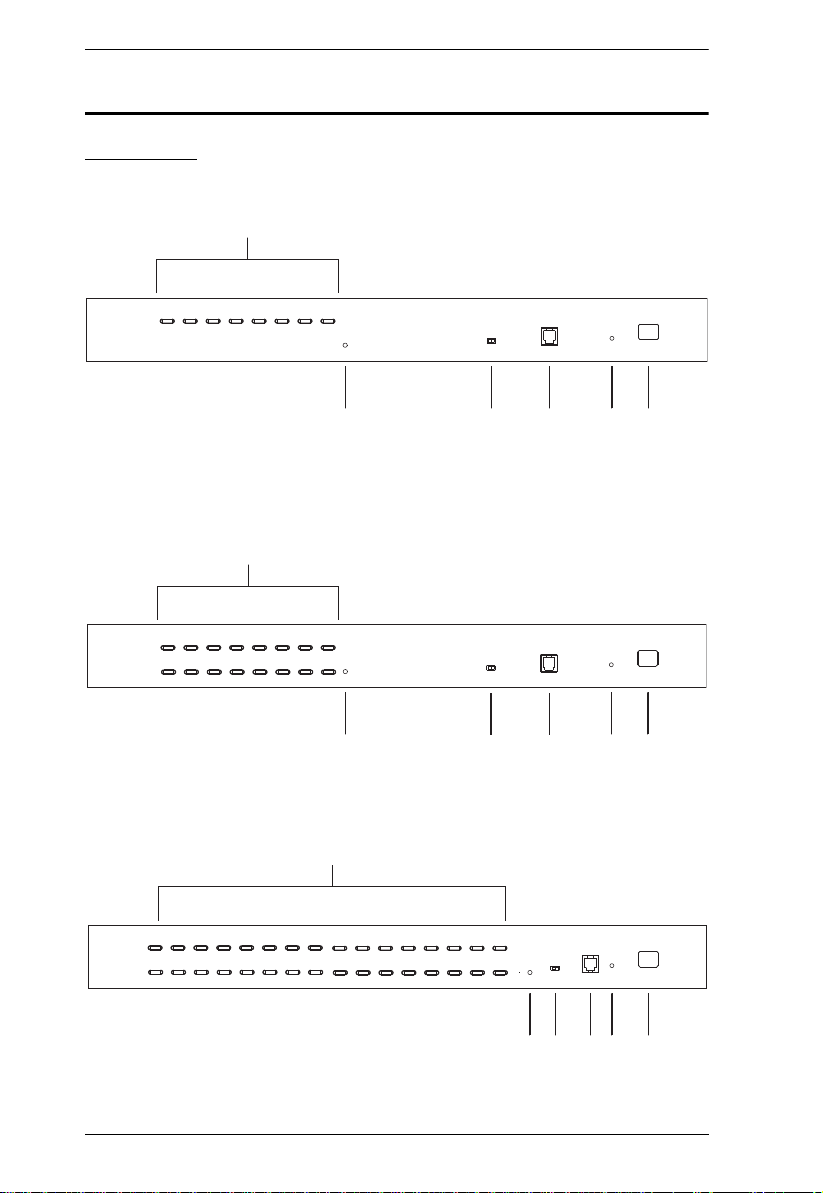
Components
Front View
KH1508A
KH1516A
KH1532A
6

Chapter 1. Introduction
No. Component Description
1 Port Selection
Pushbuttons
2 Port LEDs The Port LEDs are built into the Port Selection Pushbuttons.
3 Reset Switch Pressing this switch in performs a system reset.
4 Firmware
Upgrade
Recovery
Switch
5 Firmware
Upgrade Port
6 Power LED Lights to indicate that the KH1508A / KH1516A / KH1532A is
7 Station ID
LED
Press a pushbutton to give the KVM focus to the computer
attached to its corresponding port.
Simultaneously pressing pushbuttons 1 and 2 for 3 seconds
performs a keyboard and mouse reset.
Simultaneously pressing pushbuttons 7 and 8 (KH1508A) or
15 and 16 (KH1516A) or 30 and 31(KH1516A) starts Auto
Scan mode (see F7: SCAN, page 38, for auto scan details).
The left ones are the On Line LEDs; the right ones are the
Selected Port LEDs:
An On Line LED lights GREEN to indicate that the computer
attached to its corresponding port is up and running. A
flashing LED indicates that the Port is being used for
cascading to another switch.
A Selected LED lights ORANGE to indicate that the computer
attached to its corresponding port is the one that has the
KVM focus. The LED is steady under normal conditions, but
flashes when its port is accessed under Auto Scan mode
(see F7: SCAN, page 38, for auto scan details).
Note: The switch is recessed and must be pushed with a small
object, such as the end of a paper clip, or a ballpoint pen.
During normal operation and while performing a firmware
upgrade, this switch should be in the NORMAL position. If a
firmware upgrade operation does not complete successfully,
this switch is used to perform a firmware upgrade recovery.
See Firmware Upgrade Recovery, page 60 for details.
The Firmware Upgrade Cable that transfers the firmware
upgrade data from the administrator's computer to the
KH1508A / KH1516A / KH1532A (see page 54), plugs into this
RJ-11 connector.
powered and ready to operate.
The KH1508A / KH1516A / KH1532A’s Station ID is displayed
here. If this is a single station installation (see page 14), or the
first station on a daisy chained installation (see page 16), the
KH1508A / KH1516A / KH1532A has a station ID of 01.
On a daisy chained installation, the KH1508A / KH1516A /
KH1532A auto-senses its position and displays the station ID
that corresponds to its place in the chain. (see Port ID
Numbering, page 24, for details).
7
KH1508A / KH1516A / KH1532A User Manual
3
3
3
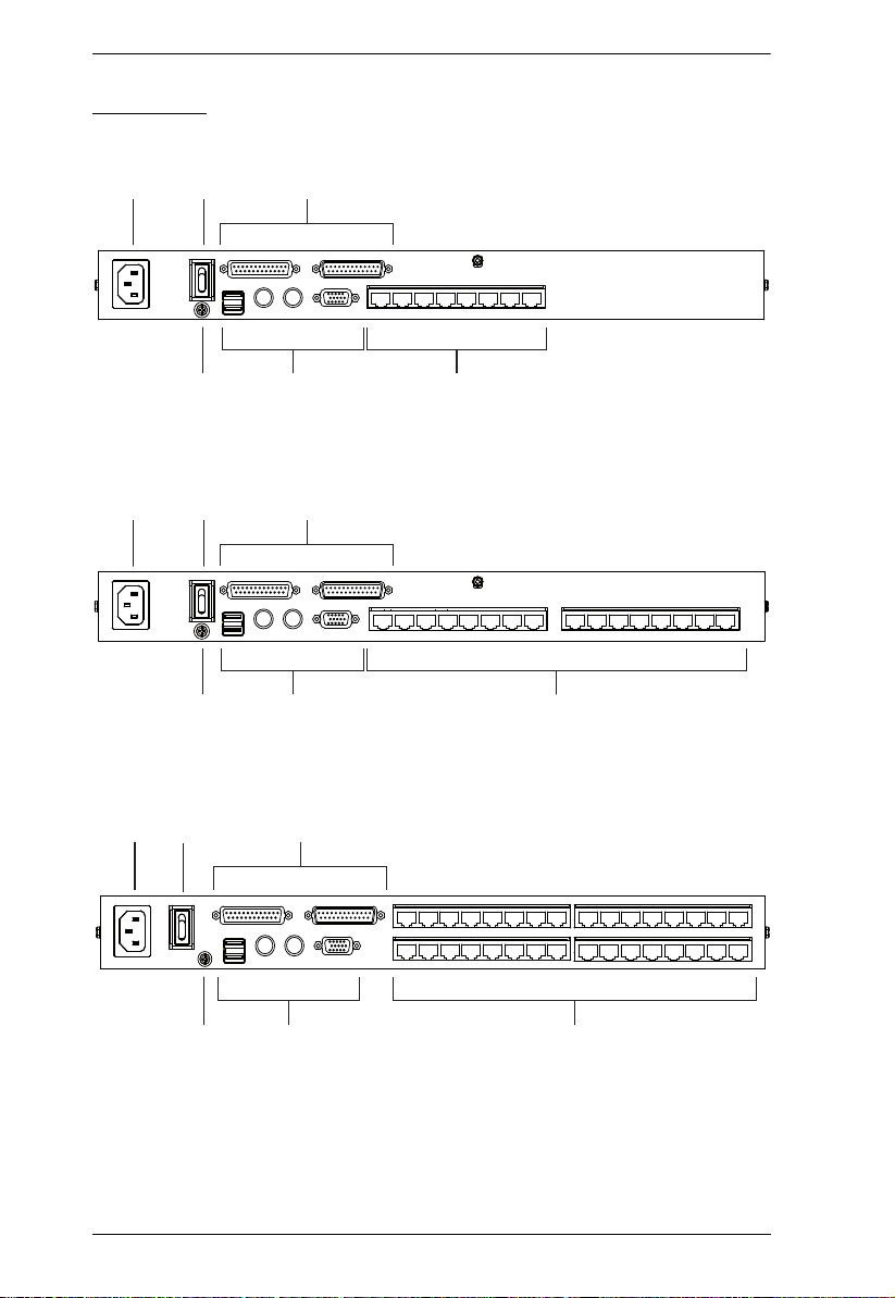
Rear View
KH1508A
12
KH1516A
12
KH1532A
1
2
45
45
6
6
45
6
8

Chapter 1. Introduction
No. Component Description
1 Power Socket The power cord to the AC source plugs in here.
2 Power Switch This is a standard rocker switch that powers the KH1508A /
KH1516A / KH1532A on and off.
3 Daisy Chain
Ports
When daisy chaining units (see Daisy Chaining, page 18),
the daisy chain cables plug in here. The port on the left is the
Chain In port and the port on the right is the Chain Out port.
4 Grounding
The wire used to ground the unit connects here.
Terminal
5 Console Ports If this is a single station installation, or if this is the first station
of a daisy chained installation, the keyboard, monitor, and
mouse that make up the Local Console plug in here. You can
use any combination of PS/2 and USB keyboards and mice
for the console.
6 KVM Port
Section
The Cat 5e/6 cables that link to the KVM adapter cables
(which link to the computers) plug in here.
9

KH1508A / KH1516A / KH1532A User Manual
This Page Intentionally Left Blank
10
Chapter 2
1. Important safety information regard
ing the placement of this
device is provided on
page 63
. Please review it before proceeding.
2.
Make sure that the power to any device that you connect to the
installation has been turned off. You m
ust unplug the power cords
of any computers that have the Keyboard Power On function.
Hardware Setup
Overview
For convenience and flexibility of mixing the PS/2, USB and serial interfaces,
the KH1508A / KH1516A/ KH1532A’s design utilizes KVM adapter cables
that serve as intermediaries between the KVM switch and the connected
devices:
A separate KVM adapter cable is required for each computer or device
connection. The KVM adapter cables are listed in the KVM Adapter Cables
section on page 5. Consult your dealer to find out which KVM adapter cables
best fit your needs.
Before you Begin
11
KH1508A / KH1516A / KH1532A User Manual
Stacking and Rack Mounting
The KH1508A / KH1516A/ KH1532A can be stacked on the desktop or rack
mounted at the front or rear of the rack. The following sections take you
through the procedures for each method.
Note: 1. Allow at least 5.1 cm on each side for adequate ventilation and
12.7 cm at the rear for power cord and cable clearance.
2. The standard rack mount kit does not include rack mount screws or
cage nuts. If you need additional rack mount screws or cage nuts,
contact your rack dealer.
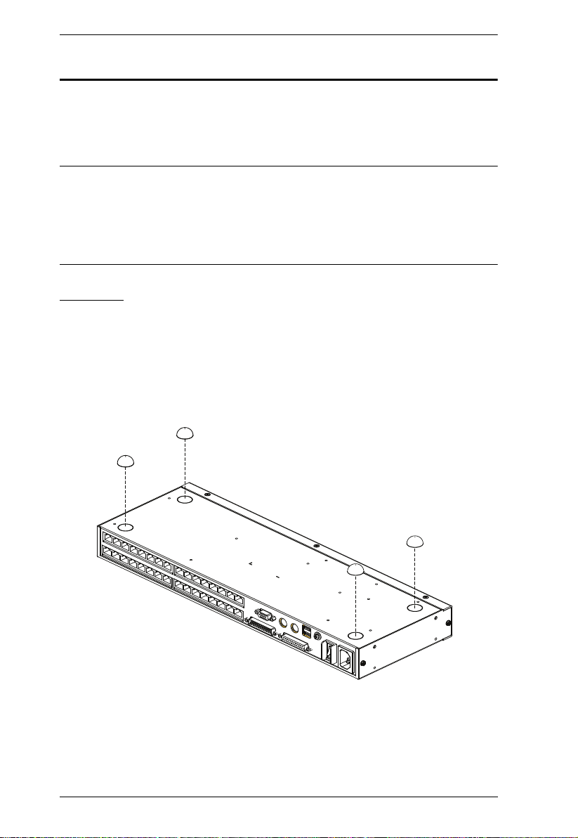
Stacking
The KH1508A / KH1516A/ KH1532A can be placed on any appropriate level
surface that can safely support its weight plus the weight of its attached cables.
To place the KH1508A / KH1516A/ KH1532A, or to stack units if you are
daisy chaining them, remove the backing material from the bottom of the
rubber feet that came with this package, and stick them onto the switch’s
bottom panel at the corners, as shown in the diagram, below:
12
Chapter 2. Hardware Setup
Phillips head hex
M3 x 6
Phillips head hex
M3 x 6
Phillips head hex
x
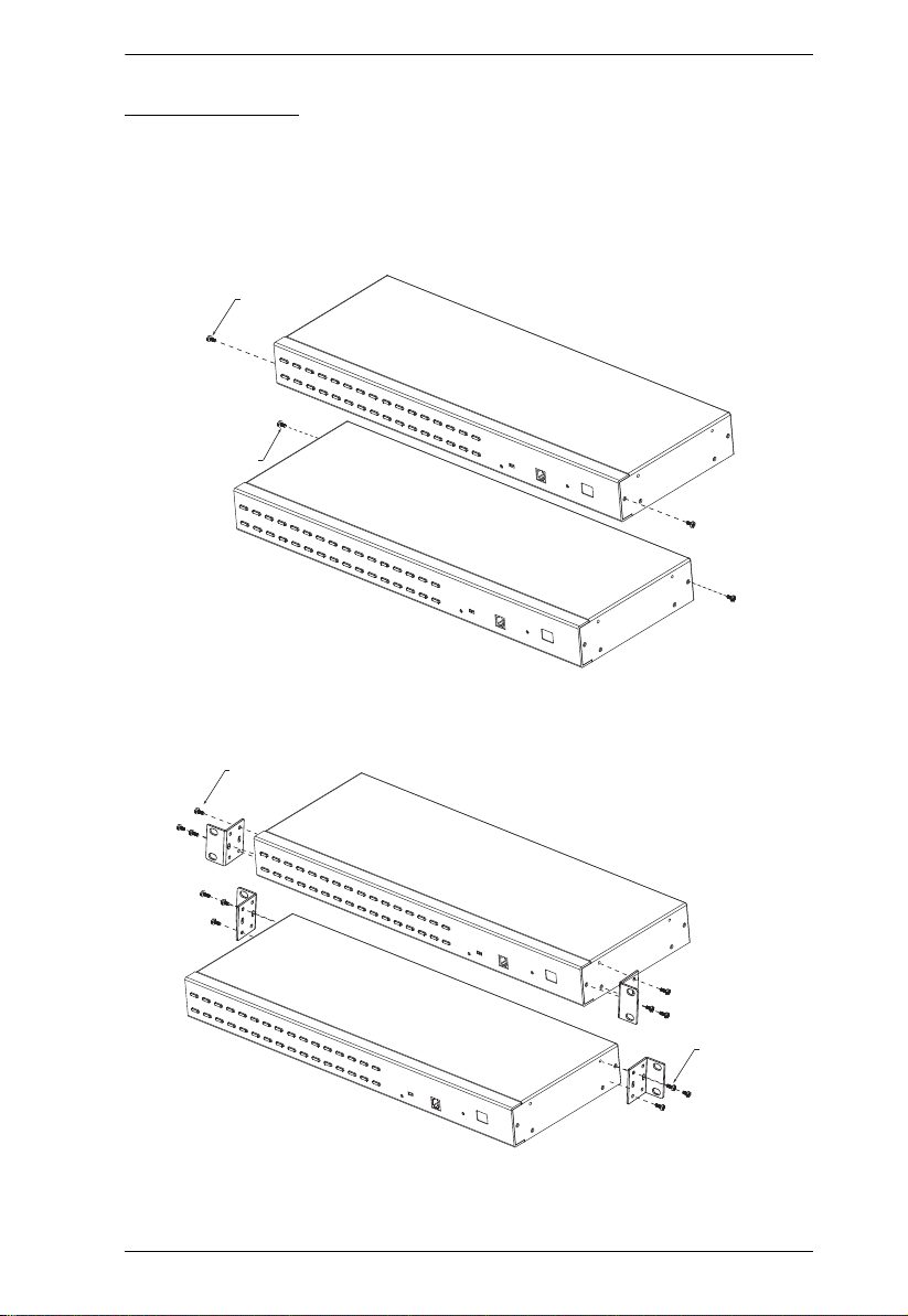
Rack Mounting
Th e KH1 508A / KH15 16A/ K H153 2A ca n be m ounted in a 19" ( 1U) rack. The
mounting brackets can screw into either the front or the back of the unit so that
it can attach to the front or the back of the rack. To rack mount the unit:
1. Remove the screws at the front or the rear, as shown in the diagram below.
2. Screw the mounting brackets into the sides of the unit at the front or the
rear, as shown in the diagram below.
M3 x 8
Phillips head he
M3 x 8
3. Slide the unit into the front or rear of the rack and secure it to the rack.
13

KH1508A / KH1516A / KH1532A User Manual
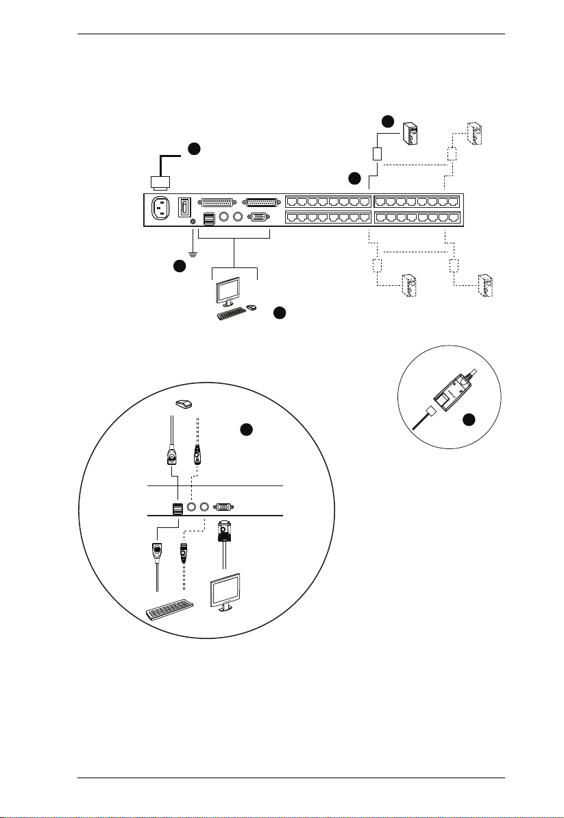
Single Station Installation
In a single stage installation, one KH1508A / KH1516A/ KH1532A is used.
Refer to the installation diagrams starting on page 15 (the numbers in the
diagram correspond with the numbers of the instruction steps) and do the
following:
1. Ground the KH1508A / KH1516A/ KH1532A by connecting one end of a
grounding wire to the grounding terminal, and the other end of the wire to
a suitable grounded object.
Note: Do not omit this step. Proper grounding helps to prevent damage to
the unit from surges or static electricity.
2. Plug the console keyboard, monitor, and mouse into the unit’s console
ports. The ports are color coded and marked with icons for easy
identification.
Note: You can use any combination of keyboard and mouse connections.
For example, you can use a PS/2 keyboard with a USB mouse.
3. Use Cat 5e/6 cable to connect any available KVM port to a KVM adapter
cable that is appropriate for the computer you are installing (see KVM
Adapter Cables, page 5 for details).
Note: To support a resolution of 1280x1024, the recommended maximum
distance between the unit and the KVM adapter cable is 50 meters.
4. Connect the KVM adapter cable to the computer.
Plug the connectors on the KVM adapter cable into the appropriate ports
of the computer you are installing. (See KVM Adapter Cable Installation
Diagrams, page 16 for connection examples.)
5. Plug the female end of the power cord into the KH1508A / KH1516A/
KH1532A's power socket; plug the male end into an AC power source.
After the KH1508A / KH1516A/ KH1532A is cabled up, you can turn on the
power. After it is powered up, you can turn on the servers.
14
Single Stage Installation Diagram
5
1
2
Chapter 2. Hardware Setup
4
3
LINK
TEN
0
0
A
2
2
y
b
1
1
E
E
9
9
A
A
MODUL
MODUL
NO. K
NO. K
PU
PU
C
C
2
2
MODEL
MODEL
PS/
PS/
2
3
15
KH1508A / KH1516A / KH1532A User Manual
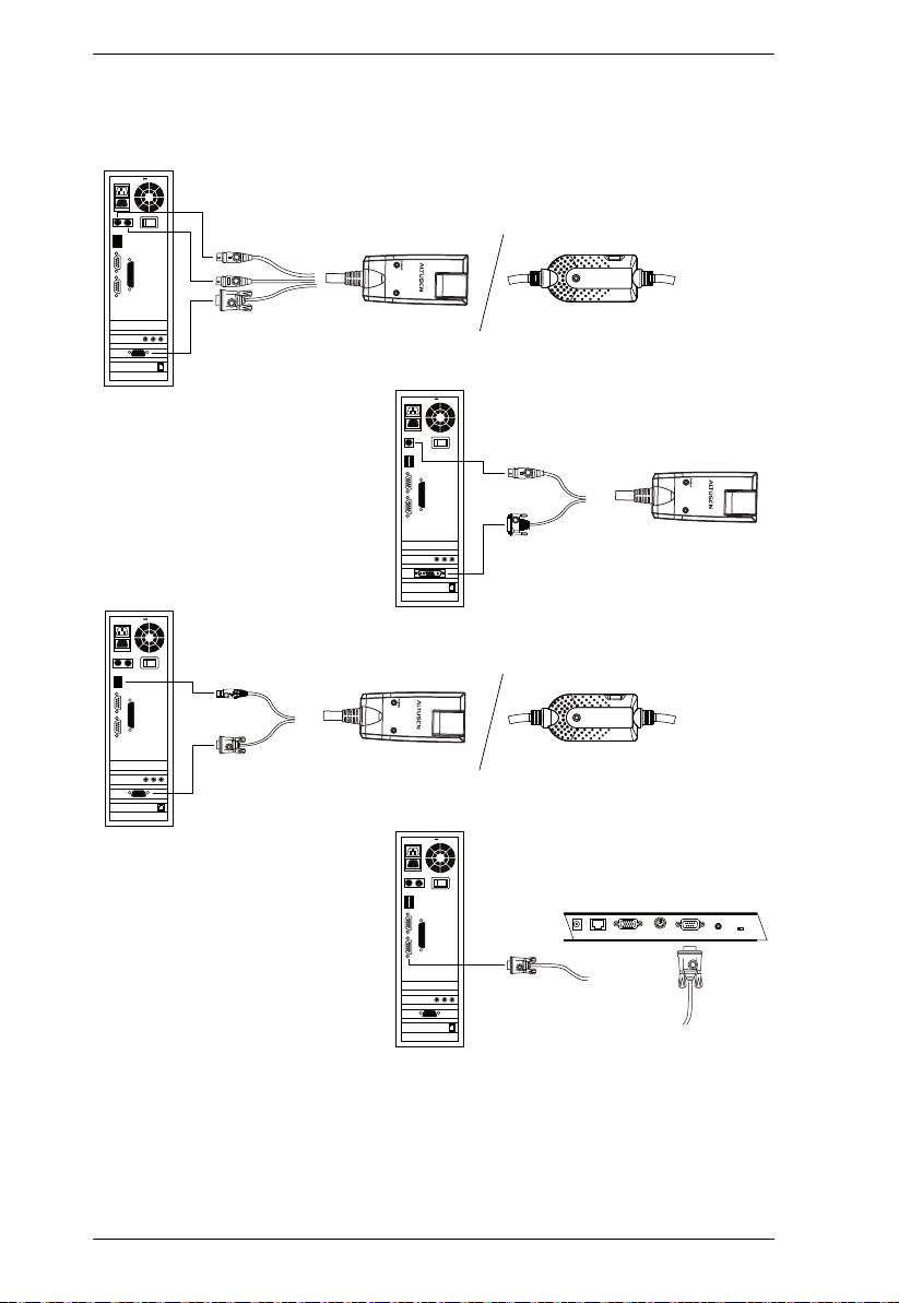
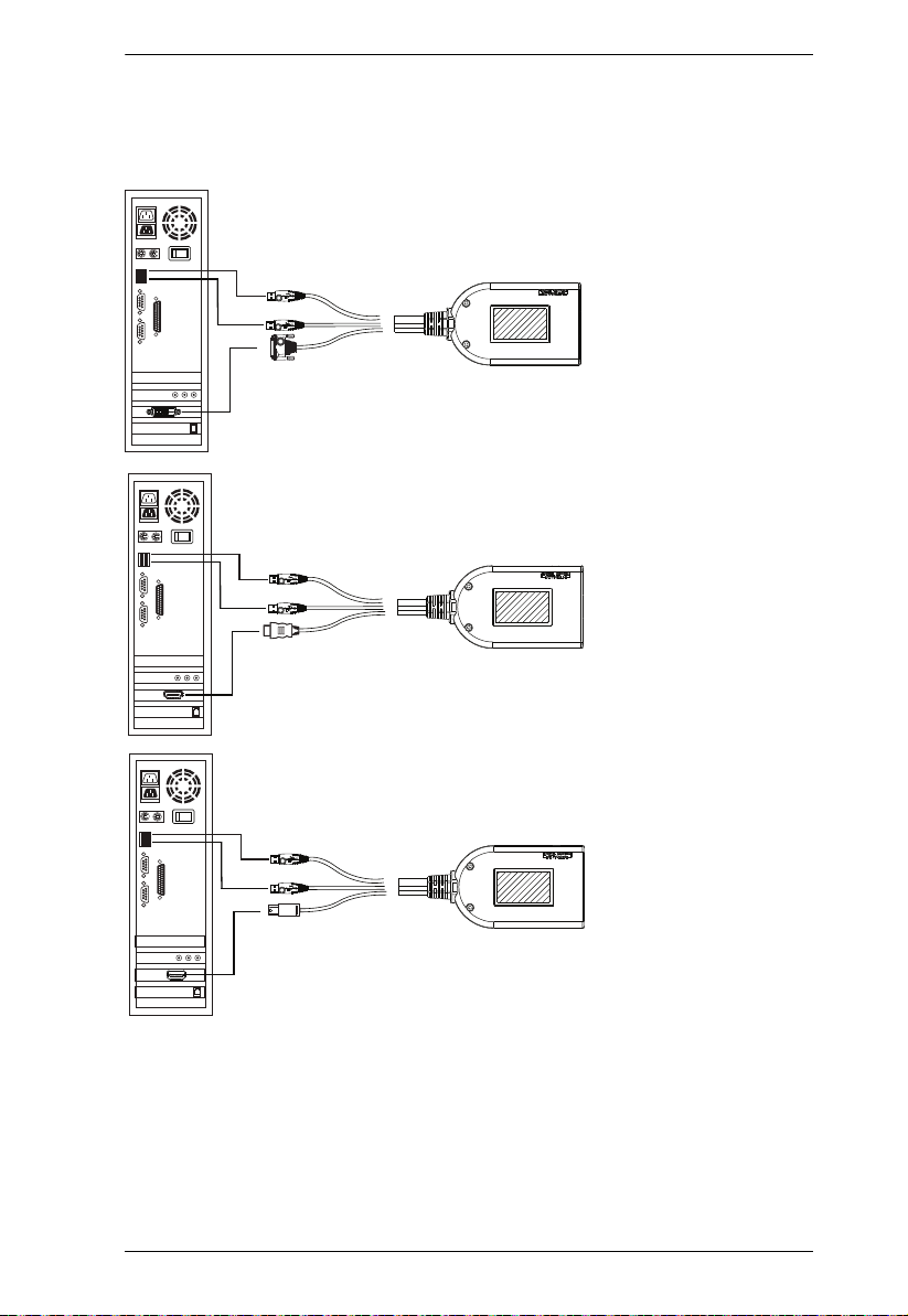
KVM Adapter Cable Installation Diagrams
LIN
b
y A
K
TEN
KA7120
KA7520
KA7920
KA9120
KA9520
KA7130
KA9130
LIN
b
y A
K
TEN
16
KA7170
KA7570
KA7970
KA9170
KA9570
LIN
b
y A
K
TEN
SERIAL TERMINAL
KA9140
Chapter 2. Hardware Setup
8
9
KVM Adapter Cable Installation Diagrams cont.
KA7166
KA716
KA716
17
 Loading...