

ATEN GN0116 Installation Manual

Installation Guide
GN0116 Guardian Over the NET™
www.aten.com
Ì
Installation Process
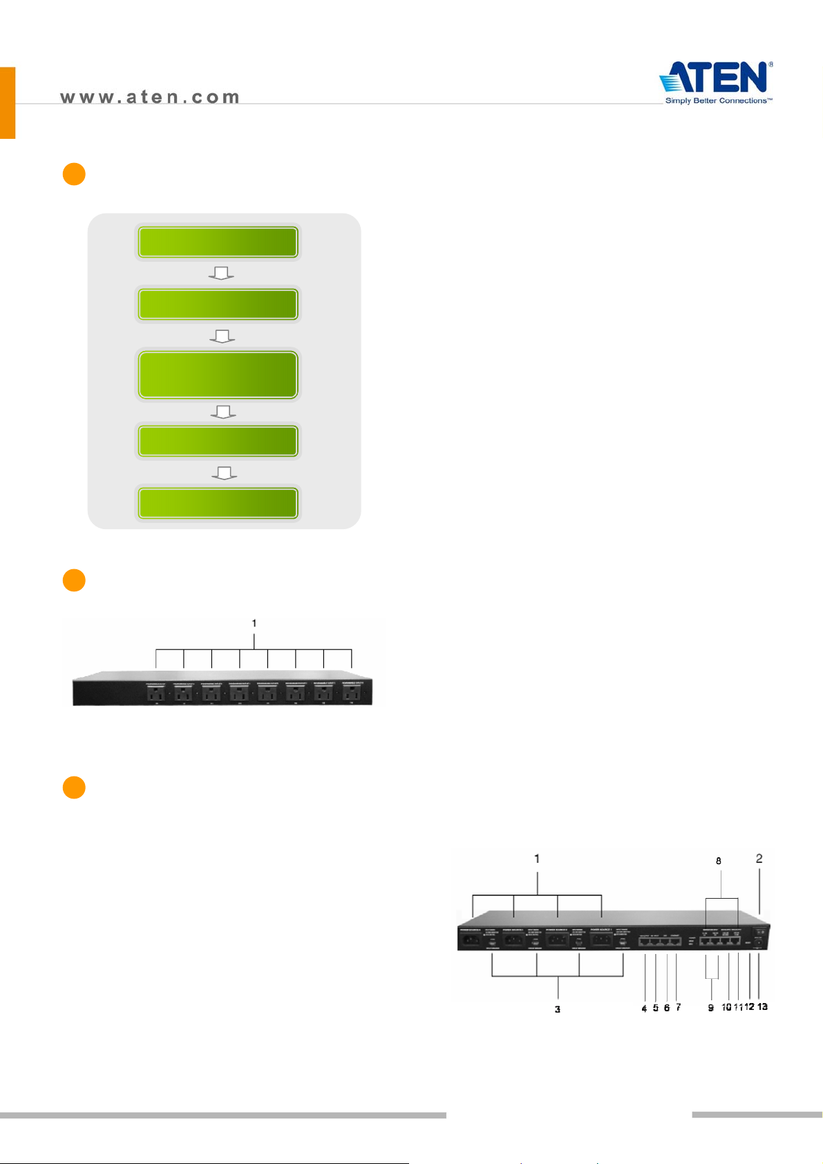
etc.
7. Ethernet: Used for browser connections to the
GN0116 from remote systems.
Hardware Installation
IP Setting
Guardian Monitor Center Server
Installation
Sensor Installation
Configuration/Operation
Ì
Product Front View
8. Ports101, 102; 103,104; 105,106; and 107,108 are
digital output ports. The output voltage is 12VDC;
50mA. They can operate buzzers, warning lights
and other similar devices. They can also be
connected to an extension unit and used as
programmable power outlets.
9. Ports 1, 2 and 3, 4 are resistance type analog
input ports. The input resistance ranges from
2~205KΩ. The ports have 1024 levels of
resolution. With appropriate drivers, they can be
connected to thermistor or other
resistance-output sensors (such as CDS sensors).
10. Ports 201,202 are digital input ports (dry contact).
They can be connected to On/Off-type output
sensors (such as intrusion, access control, smoke,
and leakage sensors).
11. Ports 31, 32 are voltage-type analog input ports.
(Front View)
1. Programmable AC Power Outlets
Ì
Product Rear View
1. AC Power Source Inlet
2. Power Switch
3. Circuit Breaker Switches
4. 485 Output: In a daisy chained installation this is
the chain out port of the parent station.
5. 485 Input: In a daisy chained installation this is
the chain in port of the child station.
6. 232C: Used for a serial connection (either from a
modem or a direct terminal connection from a
local console) for monitoring, software updating,
The input voltage ranges from 0~5VDC. The ports
have 1024 levels of resolution. With appropriate
drivers, they can be connected to sensors with
0~5 VDC output voltage, such as AC/DC voltage
sensors, current sensors and humidity sensors.
12. Reset Switch
13. Power Input
01
GN0116 Guardian Over the NET™
Installation Guide
Ì
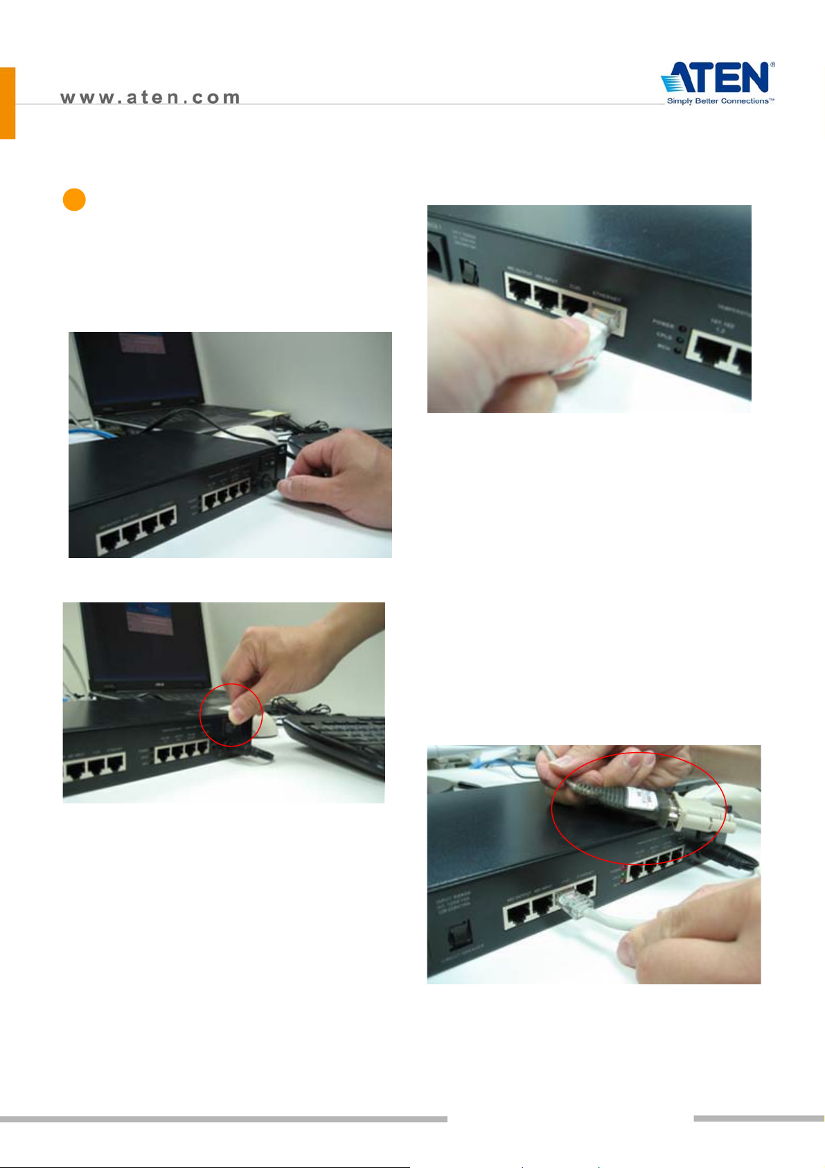
Hardware - Basic Installation
> Power Connection
1. Connect one end of the bundled Power Adapter to
the AC power source and the other end to the AC
power source inlet on the rear panel.
2. Turn on the GN0116's power switch.
network cable into the RJ-45 port to connect the
GN0116 to the network.
> RS-232 Connection
If you choose to use the RS-232 connection, connect
the RJ-45 connector on the bundled RS-232-to-RJ-45
cable to the port marked as 232C on the panel and the
RS-232 to the corresponding device (Computer COM
port or the MODEM port); as the demonstrator is using
a notebook computer, an additional ATEN UC232A was
used to convert the RS-232 signal to USB so it can be
passed to the notebook computer through the USB
interface.
The GN0116 supports two types of network
connections – over the Ethernet or through RS-232.
RS-232 can be connected to a modem to support a
Dial-up connection. It can also be connected directly
to the computer COM Port so commands can be issued
through the RS-232 Port or for setting the Logic
Configuration and Proxy function.
> Ethernet Connection
If the Ethernet connection is used, connect the
Note: You may choose between an Ethernet or RS-232
connection. If you choose the Ethernet connection
then there is no need to connect the RS-232 port.
02
GN0116 Guardian Over the NET™
Installation Guide
 Loading...