

Page 1
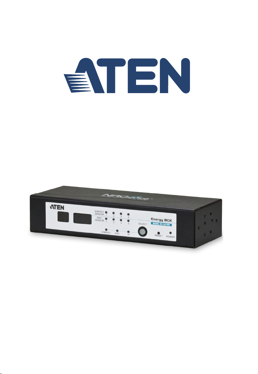
NRGence™ Energy Box
EC1000 / EC2004
User Manual
www.aten.com
Page 2

EC1000 / EC2004 User Manual
FCC, CE Information
Warning: This is a class A product. In a domestic environment this product
may cause radio interference in which case the user may be required to take
adequate measures.
FEDERAL COMMUNICATIONS COMMISSION INTERFERENCE
STATEMENT. This equipment has been tested and found to comply with the
limits for a Class A digital device, pursuant to Part 15 of the FCC Rules. These
limits are designed to provide reasonable protection against harmful
interference when the equipment is operated in a commercial environment.
This equipment generates, uses, and can radiate radio frequency energy and, if
not installed and used in accordance with the instruction manual, may cause
harmful interference to radio communications. Operation of this equipment in
a residential area is likely to cause harmful interference in which case the user
will be required to correct the interference at his own expense.
FCC Caution: Any changes or modifications not expressly approved by the
party responsible for compliance could void the user's authority to operate this
equipment.
RoHS
This product is RoHS compliant.
SJ/T 11364-2006
The following contains information that relates to China.
ii
Page 3

EC1000 / EC2004 User Manual
User Information
Online Registration
Be sure to register your product at our online support center:
International http://support.aten.com
North America http://www.aten-usa.com/product_registration
Telephone Support
For telephone support, call this number:
International 886-2-8692-6959
China 86-10-5255-0110
Japan 81-3-5615-5811
Korea 82-2-467-6789
North America 1-888-999-ATEN ext 4988
United Kingdom 44-8-4481-58923
User Notice
All information, documentation, and specifications contained in this manual
are subject to change without prior notification by the manufacturer. The
manufacturer makes no representations or warranties, either expressed or
implied, with respect to the contents hereof and specifically disclaims any
warranties as to merchantability or fitness for any particular purpose. Any of
the manufacturer's software described in this manual is sold or licensed as is.
Should the programs prove defective following their purchase, the buyer (and
not the manufacturer, its distributor, or its dealer), assumes the entire cost of all
necessary servicing, repair and any incidental or consequential damages
resulting from any defect in the software.
The manufacturer of this system is not responsible for any radio and/or TV
interference caused by unauthorized modifications to this device. It is the
responsibility of the user to correct such interference.
The manufacturer is not responsible for any damage incurred in the operation
of this system if the correct operational voltage setting was not selected prior
to operation. PLEASE VERIFY THAT THE VOLTAGE SETTING IS
CORRECT BEFORE USE.
iii
Page 4

EC1000 / EC2004 User Manual
Copyright © 2013 ATEN® International Co., Ltd.
F/W Version: 1.0.064
Manual Date: 2013-08-20
NRGence and the NRGence logo are registered trademarks of ATEN International Co., Ltd. All rights reserved.
All other brand names and trademarks are the registered property of their respective owners.
Package Contents
The EC1000 / EC2004 package consists of:
1 EC1000 / EC2004 Energy Box
1 Power Adapter
1 Mounting Kit
4RJ-45 Cables
1 CD ROM (Manual, eco Sensors Software)
1 User Instructions*
Check to make sure that all of the components are present and in good order.
If anything is missing, or was damaged in shipping, contact your dealer.
Read this manual thoroughly and follow the installation and operation
procedures carefully to prevent any damage to the switch or to any other
devices on the EC1000 / EC2004 installation.
* Features may have been added to the EC1000 / EC2004 since this manual
was published. Please visit our website to download the most up-to-date
version.
iv
Page 5

EC1000 / EC2004 User Manual
Contents
FCC, CE Information. . . . . . . . . . . . . . . . . . . . . . . . . . . . . . . . . . . . . . . . . . ii
SJ/T 11364-2006. . . . . . . . . . . . . . . . . . . . . . . . . . . . . . . . . . . . . . . . . . . . . ii
User Information . . . . . . . . . . . . . . . . . . . . . . . . . . . . . . . . . . . . . . . . . . . . .iii
Online Registration . . . . . . . . . . . . . . . . . . . . . . . . . . . . . . . . . . . . . . . .iii
Telephone Support . . . . . . . . . . . . . . . . . . . . . . . . . . . . . . . . . . . . . . . .iii
User Notice . . . . . . . . . . . . . . . . . . . . . . . . . . . . . . . . . . . . . . . . . . . . . .iii
Package Contents. . . . . . . . . . . . . . . . . . . . . . . . . . . . . . . . . . . . . . . . . . . iv
About This Manual . . . . . . . . . . . . . . . . . . . . . . . . . . . . . . . . . . . . . . . . . . ix
Conventions . . . . . . . . . . . . . . . . . . . . . . . . . . . . . . . . . . . . . . . . . . . . . x
Product Information. . . . . . . . . . . . . . . . . . . . . . . . . . . . . . . . . . . . . . . . . . . x
Chapter 1.
Introduction
Overview . . . . . . . . . . . . . . . . . . . . . . . . . . . . . . . . . . . . . . . . . . . . . . . . . . .1
Features . . . . . . . . . . . . . . . . . . . . . . . . . . . . . . . . . . . . . . . . . . . . . . . . . . .3
Requirements . . . . . . . . . . . . . . . . . . . . . . . . . . . . . . . . . . . . . . . . . . . . . . . 5
Optional Accessories . . . . . . . . . . . . . . . . . . . . . . . . . . . . . . . . . . . . . . . . .6
Sensors . . . . . . . . . . . . . . . . . . . . . . . . . . . . . . . . . . . . . . . . . . . . . . . . .6
Door Sensor . . . . . . . . . . . . . . . . . . . . . . . . . . . . . . . . . . . . . . . . . . . . .6
Sensor Management . . . . . . . . . . . . . . . . . . . . . . . . . . . . . . . . . . . . . . .6
Components . . . . . . . . . . . . . . . . . . . . . . . . . . . . . . . . . . . . . . . . . . . . . . . . 7
EC1000 Front View . . . . . . . . . . . . . . . . . . . . . . . . . . . . . . . . . . . . . . . . 7
EC1000 Rear View . . . . . . . . . . . . . . . . . . . . . . . . . . . . . . . . . . . . . . . . 8
EC2004 Front View . . . . . . . . . . . . . . . . . . . . . . . . . . . . . . . . . . . . . . . . 9
EC2004 Rear View . . . . . . . . . . . . . . . . . . . . . . . . . . . . . . . . . . . . . . . 10
Chapter 2.
Hardware Setup
Rack Mounting . . . . . . . . . . . . . . . . . . . . . . . . . . . . . . . . . . . . . . . . . . . . . 11
Rack Mounting - Front. . . . . . . . . . . . . . . . . . . . . . . . . . . . . . . . . . . . .11
Rack Mounting - Rear . . . . . . . . . . . . . . . . . . . . . . . . . . . . . . . . . . . . .13
Rack Mounting - Side . . . . . . . . . . . . . . . . . . . . . . . . . . . . . . . . . . . . .14
Installation. . . . . . . . . . . . . . . . . . . . . . . . . . . . . . . . . . . . . . . . . . . . . . . . .15
Securing the Sensors . . . . . . . . . . . . . . . . . . . . . . . . . . . . . . . . . . . . .17
Chapter 3.
Front Panel Operation
Overview . . . . . . . . . . . . . . . . . . . . . . . . . . . . . . . . . . . . . . . . . . . . . . . . . .19
Front Panel Operation . . . . . . . . . . . . . . . . . . . . . . . . . . . . . . . . . . . . .19
Chapter 4.
EC1000 Browser Operation
Operation Methods . . . . . . . . . . . . . . . . . . . . . . . . . . . . . . . . . . . . . . . . . .21
Browser . . . . . . . . . . . . . . . . . . . . . . . . . . . . . . . . . . . . . . . . . . . . . . . .21
v
Page 6

EC1000 / EC2004 User Manual
eco Sensors . . . . . . . . . . . . . . . . . . . . . . . . . . . . . . . . . . . . . . . . . . . . 21
SNMP . . . . . . . . . . . . . . . . . . . . . . . . . . . . . . . . . . . . . . . . . . . . . . . . . 21
Browser Login. . . . . . . . . . . . . . . . . . . . . . . . . . . . . . . . . . . . . . . . . . . . . . 22
The EC1000 Main Page . . . . . . . . . . . . . . . . . . . . . . . . . . . . . . . . . . . . . . 23
Page Components . . . . . . . . . . . . . . . . . . . . . . . . . . . . . . . . . . . . . . . 24
Browser Operation . . . . . . . . . . . . . . . . . . . . . . . . . . . . . . . . . . . . . . . . . . 25
First Time Setup . . . . . . . . . . . . . . . . . . . . . . . . . . . . . . . . . . . . . . . . . 25
Network Configuration. . . . . . . . . . . . . . . . . . . . . . . . . . . . . . . . . . . . . 26
Changing the Administrator Login. . . . . . . . . . . . . . . . . . . . . . . . . . . . 27
Access . . . . . . . . . . . . . . . . . . . . . . . . . . . . . . . . . . . . . . . . . . . . . . . . . . . 28
Connections . . . . . . . . . . . . . . . . . . . . . . . . . . . . . . . . . . . . . . . . . . . . 28
Energy Sensor Status . . . . . . . . . . . . . . . . . . . . . . . . . . . . . . . . . . 29
Environment Sensor Status. . . . . . . . . . . . . . . . . . . . . . . . . . . . . . 30
Configuration. . . . . . . . . . . . . . . . . . . . . . . . . . . . . . . . . . . . . . . . . . . . 31
User Management . . . . . . . . . . . . . . . . . . . . . . . . . . . . . . . . . . . . . . . . . . 32
Administrator Information . . . . . . . . . . . . . . . . . . . . . . . . . . . . . . . . . . 32
User Information . . . . . . . . . . . . . . . . . . . . . . . . . . . . . . . . . . . . . . . . . 32
Log . . . . . . . . . . . . . . . . . . . . . . . . . . . . . . . . . . . . . . . . . . . . . . . . . . . . . . 34
The System Log Event List . . . . . . . . . . . . . . . . . . . . . . . . . . . . . . . . . 34
Device Management. . . . . . . . . . . . . . . . . . . . . . . . . . . . . . . . . . . . . . . . . 35
Device Configuration. . . . . . . . . . . . . . . . . . . . . . . . . . . . . . . . . . . . . . 35
General . . . . . . . . . . . . . . . . . . . . . . . . . . . . . . . . . . . . . . . . . . . . . 35
Service Ports . . . . . . . . . . . . . . . . . . . . . . . . . . . . . . . . . . . . . . . . . 36
IPv4 Configuration. . . . . . . . . . . . . . . . . . . . . . . . . . . . . . . . . . . . . 37
Event Notification . . . . . . . . . . . . . . . . . . . . . . . . . . . . . . . . . . . . . 38
Date/Time . . . . . . . . . . . . . . . . . . . . . . . . . . . . . . . . . . . . . . . . . . . . . . 41
Time Zone . . . . . . . . . . . . . . . . . . . . . . . . . . . . . . . . . . . . . . . . . . . 41
Manual Input . . . . . . . . . . . . . . . . . . . . . . . . . . . . . . . . . . . . . . . . . 42
Network Time . . . . . . . . . . . . . . . . . . . . . . . . . . . . . . . . . . . . . . . . 42
Finishing Up . . . . . . . . . . . . . . . . . . . . . . . . . . . . . . . . . . . . . . . . . 42
Security . . . . . . . . . . . . . . . . . . . . . . . . . . . . . . . . . . . . . . . . . . . . . . . . 43
Login Failures . . . . . . . . . . . . . . . . . . . . . . . . . . . . . . . . . . . . . . . . . . . 43
Working Mode. . . . . . . . . . . . . . . . . . . . . . . . . . . . . . . . . . . . . . . . . . . 43
Account Policy. . . . . . . . . . . . . . . . . . . . . . . . . . . . . . . . . . . . . . . . . . . 44
Login String / IP Filter / Mac Filter. . . . . . . . . . . . . . . . . . . . . . . . . . . . 45
Adding Filters . . . . . . . . . . . . . . . . . . . . . . . . . . . . . . . . . . . . . . . . 46
IP Filter / MAC Filter Conflict . . . . . . . . . . . . . . . . . . . . . . . . . . . . . 47
Modifying Filters . . . . . . . . . . . . . . . . . . . . . . . . . . . . . . . . . . . . . . 47
Deleting Filters . . . . . . . . . . . . . . . . . . . . . . . . . . . . . . . . . . . . . . . 47
Authentication & Authorization . . . . . . . . . . . . . . . . . . . . . . . . . . . . . . 48
RADIUS Settings. . . . . . . . . . . . . . . . . . . . . . . . . . . . . . . . . . . . . . 48
Private Certificate . . . . . . . . . . . . . . . . . . . . . . . . . . . . . . . . . . . . . . . . 50
Generating a Self-Signed Certificate. . . . . . . . . . . . . . . . . . . . . . . 50
Obtaining a CA Signed SSL Server Certificate . . . . . . . . . . . . . . . 50
Importing the Private Certificate . . . . . . . . . . . . . . . . . . . . . . . . . . 50
Maintenance . . . . . . . . . . . . . . . . . . . . . . . . . . . . . . . . . . . . . . . . . . . . . . . 51
vi
Page 7

EC1000 / EC2004 User Manual
Firmware File. . . . . . . . . . . . . . . . . . . . . . . . . . . . . . . . . . . . . . . . . . . . 51
Backup/Restore. . . . . . . . . . . . . . . . . . . . . . . . . . . . . . . . . . . . . . . . . .53
Backup. . . . . . . . . . . . . . . . . . . . . . . . . . . . . . . . . . . . . . . . . . . . . . 53
Restore . . . . . . . . . . . . . . . . . . . . . . . . . . . . . . . . . . . . . . . . . . . . .53
Chapter 5.
EC2004 Browser Operation
Operation Methods . . . . . . . . . . . . . . . . . . . . . . . . . . . . . . . . . . . . . . . . . .55
Browser . . . . . . . . . . . . . . . . . . . . . . . . . . . . . . . . . . . . . . . . . . . . . . . .55
eco Sensors . . . . . . . . . . . . . . . . . . . . . . . . . . . . . . . . . . . . . . . . . . . .55
SNMP . . . . . . . . . . . . . . . . . . . . . . . . . . . . . . . . . . . . . . . . . . . . . . . . .55
Browser Login . . . . . . . . . . . . . . . . . . . . . . . . . . . . . . . . . . . . . . . . . . . . . .56
The EC2004 Main Page . . . . . . . . . . . . . . . . . . . . . . . . . . . . . . . . . . . . . .57
Page Components. . . . . . . . . . . . . . . . . . . . . . . . . . . . . . . . . . . . . . . .57
Browser Operation . . . . . . . . . . . . . . . . . . . . . . . . . . . . . . . . . . . . . . . . . .59
First Time Setup . . . . . . . . . . . . . . . . . . . . . . . . . . . . . . . . . . . . . . . . .59
Network Configuration. . . . . . . . . . . . . . . . . . . . . . . . . . . . . . . . . . . . . 60
Changing the Administrator Login . . . . . . . . . . . . . . . . . . . . . . . . . . . .61
Access. . . . . . . . . . . . . . . . . . . . . . . . . . . . . . . . . . . . . . . . . . . . . . . . . . . . 62
Connections . . . . . . . . . . . . . . . . . . . . . . . . . . . . . . . . . . . . . . . . . . . . 62
Energy Sensor Status . . . . . . . . . . . . . . . . . . . . . . . . . . . . . . . . . .63
Monitor Status . . . . . . . . . . . . . . . . . . . . . . . . . . . . . . . . . . . . . . . . 64
Configuration . . . . . . . . . . . . . . . . . . . . . . . . . . . . . . . . . . . . . . . . . . . .65
User Management. . . . . . . . . . . . . . . . . . . . . . . . . . . . . . . . . . . . . . . . . . .66
Administrator Information . . . . . . . . . . . . . . . . . . . . . . . . . . . . . . . . . .66
User Information . . . . . . . . . . . . . . . . . . . . . . . . . . . . . . . . . . . . . . . . . 66
Log . . . . . . . . . . . . . . . . . . . . . . . . . . . . . . . . . . . . . . . . . . . . . . . . . . . . . .68
The System Log Event List . . . . . . . . . . . . . . . . . . . . . . . . . . . . . . . . .68
Notification Settings. . . . . . . . . . . . . . . . . . . . . . . . . . . . . . . . . . . . . . . 69
Setup. . . . . . . . . . . . . . . . . . . . . . . . . . . . . . . . . . . . . . . . . . . . . . . . . . . . .70
Device Configuration . . . . . . . . . . . . . . . . . . . . . . . . . . . . . . . . . . . . . .70
General . . . . . . . . . . . . . . . . . . . . . . . . . . . . . . . . . . . . . . . . . . . . .70
Service Ports . . . . . . . . . . . . . . . . . . . . . . . . . . . . . . . . . . . . . . . . .71
IPv4 Configuration . . . . . . . . . . . . . . . . . . . . . . . . . . . . . . . . . . . . .72
IPv6 Configuration . . . . . . . . . . . . . . . . . . . . . . . . . . . . . . . . . . . . .73
Event Notification. . . . . . . . . . . . . . . . . . . . . . . . . . . . . . . . . . . . . .74
Date/Time . . . . . . . . . . . . . . . . . . . . . . . . . . . . . . . . . . . . . . . . . . . . . .77
Time Zone . . . . . . . . . . . . . . . . . . . . . . . . . . . . . . . . . . . . . . . . . . .77
Manual Input . . . . . . . . . . . . . . . . . . . . . . . . . . . . . . . . . . . . . . . . .78
Network Time. . . . . . . . . . . . . . . . . . . . . . . . . . . . . . . . . . . . . . . . .78
Finishing Up. . . . . . . . . . . . . . . . . . . . . . . . . . . . . . . . . . . . . . . . . .78
Security . . . . . . . . . . . . . . . . . . . . . . . . . . . . . . . . . . . . . . . . . . . . . . . .79
Login Failures . . . . . . . . . . . . . . . . . . . . . . . . . . . . . . . . . . . . . . . . . . .79
Working Mode . . . . . . . . . . . . . . . . . . . . . . . . . . . . . . . . . . . . . . . . . . .79
Account Policy. . . . . . . . . . . . . . . . . . . . . . . . . . . . . . . . . . . . . . . . . . .80
Login String / IP Filter / Mac Filter. . . . . . . . . . . . . . . . . . . . . . . . . . . . 81
vii
Page 8

EC1000 / EC2004 User Manual
Adding Filters . . . . . . . . . . . . . . . . . . . . . . . . . . . . . . . . . . . . . . . . 82
IP Filter / MAC Filter Conflict . . . . . . . . . . . . . . . . . . . . . . . . . . . . . 83
Modifying Filters . . . . . . . . . . . . . . . . . . . . . . . . . . . . . . . . . . . . . . 83
Deleting Filters . . . . . . . . . . . . . . . . . . . . . . . . . . . . . . . . . . . . . . . 83
Authentication & Authorization . . . . . . . . . . . . . . . . . . . . . . . . . . . . . . 84
RADIUS Settings. . . . . . . . . . . . . . . . . . . . . . . . . . . . . . . . . . . . . . 84
Private Certificate . . . . . . . . . . . . . . . . . . . . . . . . . . . . . . . . . . . . . . . . 86
Generating a Self-Signed Certificate. . . . . . . . . . . . . . . . . . . . . . . 86
Obtaining a CA Signed SSL Server Certificate . . . . . . . . . . . . . . . 86
Importing the Private Certificate . . . . . . . . . . . . . . . . . . . . . . . . . . 86
PDU . . . . . . . . . . . . . . . . . . . . . . . . . . . . . . . . . . . . . . . . . . . . . . . . . . . . . 87
Firmware File . . . . . . . . . . . . . . . . . . . . . . . . . . . . . . . . . . . . . . . . . . . 87
Backup/Restore. . . . . . . . . . . . . . . . . . . . . . . . . . . . . . . . . . . . . . . . . . 89
Backup . . . . . . . . . . . . . . . . . . . . . . . . . . . . . . . . . . . . . . . . . . . . . 89
Restore . . . . . . . . . . . . . . . . . . . . . . . . . . . . . . . . . . . . . . . . . . . . . 89
Appendix
Safety Instructions . . . . . . . . . . . . . . . . . . . . . . . . . . . . . . . . . . . . . . . . . . 91
General . . . . . . . . . . . . . . . . . . . . . . . . . . . . . . . . . . . . . . . . . . . . . . . . 91
Rack Mounting . . . . . . . . . . . . . . . . . . . . . . . . . . . . . . . . . . . . . . . . . . 93
Technical Support. . . . . . . . . . . . . . . . . . . . . . . . . . . . . . . . . . . . . . . . . . . 94
International . . . . . . . . . . . . . . . . . . . . . . . . . . . . . . . . . . . . . . . . . . . . 94
North America . . . . . . . . . . . . . . . . . . . . . . . . . . . . . . . . . . . . . . . . . . . 94
Specifications . . . . . . . . . . . . . . . . . . . . . . . . . . . . . . . . . . . . . . . . . . . . . . 95
EC1000 . . . . . . . . . . . . . . . . . . . . . . . . . . . . . . . . . . . . . . . . . . . . . . . . 95
EC2004 . . . . . . . . . . . . . . . . . . . . . . . . . . . . . . . . . . . . . . . . . . . . . . . . 96
IP Address Determination. . . . . . . . . . . . . . . . . . . . . . . . . . . . . . . . . . . . . 97
Method 1: . . . . . . . . . . . . . . . . . . . . . . . . . . . . . . . . . . . . . . . . . . . 97
Method 2: . . . . . . . . . . . . . . . . . . . . . . . . . . . . . . . . . . . . . . . . . . . 98
Method 3: . . . . . . . . . . . . . . . . . . . . . . . . . . . . . . . . . . . . . . . . . . . 98
IPv6. . . . . . . . . . . . . . . . . . . . . . . . . . . . . . . . . . . . . . . . . . . . . . . . . . . . . . 99
Link Local IPv6 Address . . . . . . . . . . . . . . . . . . . . . . . . . . . . . . . . . . . 99
IPv6 Stateless Autoconfiguration . . . . . . . . . . . . . . . . . . . . . . . . . . . 100
Administrator Login Failure. . . . . . . . . . . . . . . . . . . . . . . . . . . . . . . . . . . 101
Limited Warranty. . . . . . . . . . . . . . . . . . . . . . . . . . . . . . . . . . . . . . . . . . . 102
viii
Page 9

EC1000 / EC2004 User Manual
About This Manual
This User Manual is provided to help you get the most from your EC1000 /
EC2004 system. It covers all aspects of installation, configuration and
operation. An overview of the information found in the manual is provided
below.
Chapter 1, Introduction, introduces you to the EC1000 / EC2004 System.
Its purpose, features and benefits are presented, and its front and back panel
components are described.
Chapter 2, Hardware Setup, provides step-by-step instructions for setting
up your installation, and explains some basic operation procedures.
Chapter 3, Front Panel Operation, explains how to operate the EC1000 /
EC2004 from the local console.
Chapter 4, EC1000 Browser Operation, describes how to login to the
EC1000 with a browser, and explains the functions of the icons and buttons that
appear on the opening page, and explains the administrative procedures that are
employed to configure the EC1000’s working environment.
Chapter 5, EC2004 Browser Operation, describes how to login to the
EC2004 with a browser, and explains the functions of the icons and buttons that
appear on the opening page, and explains the administrative procedures that are
employed to configure the EC2004’s working environment.
An Appendix, at the end of the manual provides technical and
troubleshooting information.
ix
Page 10

EC1000 / EC2004 User Manual
Conventions
This manual uses the following conventions:
Monospaced Indicates text that you should key in.
[ ] Indicates keys you should press. For example, [Enter] means
to press the Enter key. If keys need to be chorded, they appear
together in the same bracket with a plus sign between them:
[Ctrl+Alt].
1. Numbered lists represent procedures with sequential steps.
♦ Bullet lists provide information, but do not involve sequential
steps.
→ Indicates selecting the option (on a menu or dialog box, for
example), that comes next. For example, Start
to open the Start menu, and then select Run.
Indicates critical information.
Product Information
→ Run means
For information about all ATEN products and how they can help you connect
without limits, visit ATEN on the Web or contact an ATEN Authorized
Reseller. Visit ATEN on the Web for a list of locations and telephone numbers:
International http://www.aten.com
North America http://www.aten-usa.com
x
Page 11

Chapter 1
Introduction
Overview
The EC1000 / EC2004 Energy Box solution is the latest evolution of ATEN's
energy intelligence product line NRGence™. The EC1000 monitors the
electrical current of 4 Energy PDU's, along with room temperature, humidity,
and differential pressure using environmental sensors. The EC2004 has 4 ports
to monitor the electrical current of two PDUs and the electrical current +
voltage of two additional PDUs; and monitors room temperature, humidity and
differential pressure using four environmental sensors, plus a 4-pin dry contact
Rack Door Sensor port for external sensors to monitor rack door access. Both
Energy Boxes provide instant real-time power management and energy-saving
control for data centers– allowing you to upgrade and maintain your current IT
power resources quickly and cost-effectively.
The EC1000 / EC2004 Energy Box has four RJ-45 ports to connect to four
Energy PDUs and four RJ-11 ports to connect external sensors to monitor
environmental conditions. Each environmental sensor can provide measured
readings of temperature, humidity, and differential pressure from separate
areas of a room, giving you a wide range of monitoring and protection.
The EC1000 / EC2004 features real-time status, system logs, threshold alerts,
and event notification. The Energy Box logs power and environmental
conditions according to customizable minimum/maximum thresholds set for;
current, voltage*, temperature, humidity, and differential pressure.
The Energy Box allows the power and environmental data to be monitored by
display at the rack or remotely for easy viewing and maintenance. The Energy
Box is a standalone unit with over IP monitoring that is controlled by a builtin web GUI or ATEN's eco Sensors software.
Remote monitoring offers secure access with 128bits SSL encryption, and
customizable account policies for user management. Remote authentication
supports RADIUS and additional management interfaces including HTTP,
HTTPS, and SNMPv1&v2&v3 (Read, Write, Trap). Event notifications can be
monitored via Syslog/SMTP/SNMP trap and by audible alarm for real-time
local and remote alerting.
1
Page 12

EC1000 / EC2004 User Manual
The NRGence™ EC1000 / EC2004 Energy Box is the intelligent cost effective
solution to monitor ATEN's Energy PDUs – to ensure safe and effective
energy-saving power management.
*Only available with the EC2004 Energy Box.
2
Page 13

Chapter 1. Introduction
Features
Operation
Space saving 1U and 0U rack mounting with front, rear, and side mounting
4 RJ-45 Energy Sensor Ports to monitor four Energy PDUs (0A to 32A per
port) electrical currents (EC1000), or 2 electrical currents and 2 electrical
currents + voltage (EC2004)
4 RJ-11 Environmental Sensor Ports to monitor temperature, humidity,
and differential pressure*
Maximum Amperage Monitor 32A@100V~240V (Energy Box)
3 digit 7 segment front panel LED displays current/sensor/IP address
information
Threshold monitoring for:
Current
Voltage (EC2004)
Temperature*
Humidity*
Differential pressure*
Threshold alerting through:
Local: audible alarm and LED lights
Remote: SMTP/SNMP trap/Syslog
Management
Front panel LED indicators for current, temperature*, humidity*,
differential pressure*, and IP address at the Energy Box
Remote real-time current, voltage (EC2004), temperature*, humidity*,
and differential pressure* monitoring and management
Door Sensor support – allows the monitoring of rack mount enclosure
door access to notify users when a door has been opened (EC2004)
Management through eco Sensors Energy Management Software or 3rd
party SNMP manager
Supports name assignment for individual Energy PDUs
Multi-language GUI supports: English, Traditional Chinese, Simplified
Chinese, Japanese, Korean, German, Italian, Spanish, Portuguese, French,
Russian
3
Page 14

EC1000 / EC2004 User Manual
Event Logging – 128 line event log
Syslog support
F/W upgradable
Remote Access
Remote management via TCP/IP using built in 10/100Mbps Ethernet port
Management via built in browser based GUI
Network Interfaces: TCP/IP, UDP, HTTP, HTTPS, SSL, SMTP, DHCP,
NTP, DNS, 10Base-T/100Base-TX, auto sense, Ping
Supports SNMP Manager V1, V2, V3
Security
Strong security features include password protection and advanced
encryption technologies – utilizing 128 bit SSL
RADIUS authorization and authentication
*Requires external sensors (see Optional Accessories, page 6).
4
Page 15

Chapter 1. Introduction
Requirements
Energy PDU PE1216, PE1324, PE2220, or PE2340
Environmental Sensors EA1140, EA1240, EA1340 to monitor
environmental data
Door monitoring requires an EA1440 or EA1441 door sensor
One Cat 5e Ethernet cable to connect the EC1000 / EC2004 to the local
area network
Browsers accessing the EC1000 / EC2004 must support SSL 128 bit
encryption.
5
Page 16

EC1000 / EC2004 User Manual
Optional Accessories
Sensors
Sensors are optional accessories. You can use the EC1000 / EC2004 Energy
Box without sensors. However, if you want to have complete energy
management of your data center with the full use of the EC1000 / EC2004
Energy Box, you would need to use eco Sensors software and install 4 sensors
for each of the racks to generate more complete energy-efficient data and
charts. Sensors help you maintain a safe and highly efficient data center by
monitoring environmental conditions. Higher sensor density installations help
to generate more accurate and precise data. Available sensors are show in the
table, below:
Sensor Part Number
Temperature EA1140
Temperature / Humidity EA1240
Differential Pressure / Temperature EA1340
Door Sensor
The EC2004 features a 4-pin dry contact port for door sensors that support the
monitoring of rack mount enclosure door access to notify users when a door
has been opened. See the table below for information about the two available
door sensors. Please contact your ATEN dealer for purchasing information:
Port Part Number Sensor
Door Sensor EA1440 Photo Sensor
EA1441 Inductive Proximity Sensor
Sensor Management
Sensors can be managed via the EC1000 / EC2004’s browser based graphical
user interface (GUI) or with NRGence™ eco Sensors software that can be
downloaded from the ATEN website. The download link can be found on the
software CD provided with the EC1000 / EC2004 package.
6
Page 17

Components
EC1000 Front View
Chapter 1. Introduction
1
No. Component Description
1 Readout Section
The first single-digit LED indicates the port selected:
2
5
3
4
6
Energy Sensor (1-4)
Environmental Sensor (1-4)
IP Address (1)
The second 3-digit LED displays information related to
the first LED:
Current
Temperature, Humidity, Differential Pressure
IP Address
2 Energy and
Environmental Sensor
LEDs
3 Selection LED Lights (Green) to indicate the selection (Energy,
4 Select Button Press the Select button to cycle through the selections
5 Reset Switch This switch must be pushed with a thin object, such as
Lights (Orange) for connected Energy Sensors and
(Green) for Environmental Sensors, currently connected
to a port and taking readings.
Environment, IP) that the Readout is currently displaying.
(Energy, Environment, IP) to display their data readout
on the 3-digit LED.
the end of a paper clip.
Press and release to reboot the device.
Press and hold for more then three seconds to
reset the Energy Box to its factory default settings
6 Power LED Lights (Green) when the Energy Box is powered up and
ready to operate.
7
Page 18

EC1000 / EC2004 User Manual
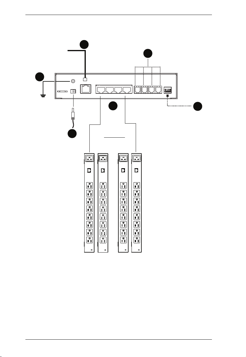
EC1000 Rear View
1
4
No. Component Description
1 Grounding Terminal The wire used to ground the Energy Box attaches here.
2 Energy Sensor Ports The four RJ-45 cables that connect the Energy Box to
3 Environmental Sensor
Ports
4 Power Jack The power adapter cable plugs into this jack.
5 LAN Port The cable that connects the Energy Box to the LAN
5
your Energy PDUs, plug in here.
External sensors plug into these four RJ-11 ports.*
plugs in here.
2
3
*External sensors are sold separately (see Optional Accessories, page 6).
8
Page 19

Chapter 1. Introduction
1
2
3
4
5
6 7
EC2004 Front View
No. Component Description
1 Readout Section
2 Energy and
Environmental Sensor
LEDs
3 Selection LED Lights (Green) to indicate the selection (Energy,
4 Select Button Press the Select button to cycle through the selections
5 Reset Switch This switch is recessed and must be pushed with a thin
6 Door Sensor Door sensor: Lights Red when the door is open.
7 Power LED Lights (Green) when the Energy Box is powered up and
The first single-digit LED indicates the port selected:
Energy Sensor (1-4)
Environmental Sensor (1-4)
IP Address (1)
The second 3-digit LED displays information related to
the first LED:
Current
Temperature, Humidity, Differential Pressure
IP Address
Lights (Orange) for connected Energy Sensors and
(Green) for Environmental Sensors, currently connected
to a port and taking readings.
Environment, IP) that the Readout is currently displaying.
(Energy, Environment, IP) to display their data readout
on the 3-digit LED.
object, such as the end of a paper clip.
Press and release to reboot the device.
Press and hold for more then three seconds to
reset the Energy Box to its factory default settings
See Door Sensor, page 6, for details.
ready to operate.
9
Page 20

EC1000 / EC2004 User Manual
EC2004 Rear View
1
4
No. Component Description
1 Grounding Terminal The wire used to ground the Energy Box attaches here.
2 Energy Sensor Ports The four RJ-45 cables that connect the Energy Box to
5
your Energy PDUs, plug in here. The electrical
measurements are as follows:
2
3
6
Port 1 Voltage / Amps
Port 2 Amps
Port 3 Voltage / Amps
Port 4 Amps
3 Environmental Sensor
Ports
4 Power Jack The power adapter cable plugs into this jack.
5 LAN Port The cable that connects the Energy Box to the LAN
6 Door Sensor Port This 4-pin dry contact port is for a door sensor which
External sensors plug into these four RJ-11 ports.*
plugs in here.
allows the monitoring of a rack mounted enclosure’s
door access to notify users when a door has been
opened. See Door Sensor, page 6, for details.
*External sensors are sold separately (see Optional Accessories, page 6).
10
Page 21
Chapter 2
1. Important safety information regarding the placement of this
device is provided on page 91. Please review it before proceeding.
Hardware Setup
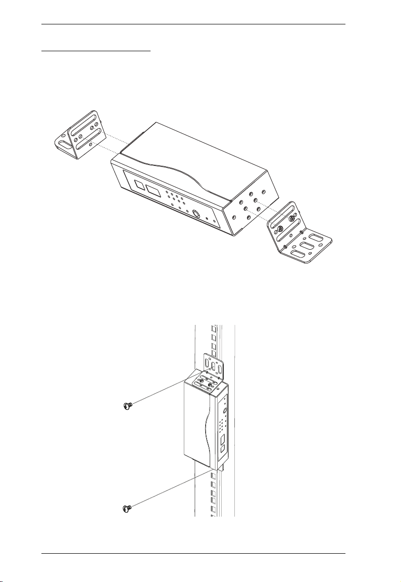
Rack Mounting
The EC1000 / EC2004 can be mounted in a 19” (1U) rack or in an 0U
configuration mounted to the side of the rack. To rack mount the device, use
the rack mounting brackets that came with your device. The brackets are
screwed to the front, rear or middle sides of the device, depending on the
installation type and then the unit can slide into the front of the rack, or mount
to the side of the rack, as shown in the diagrams below:
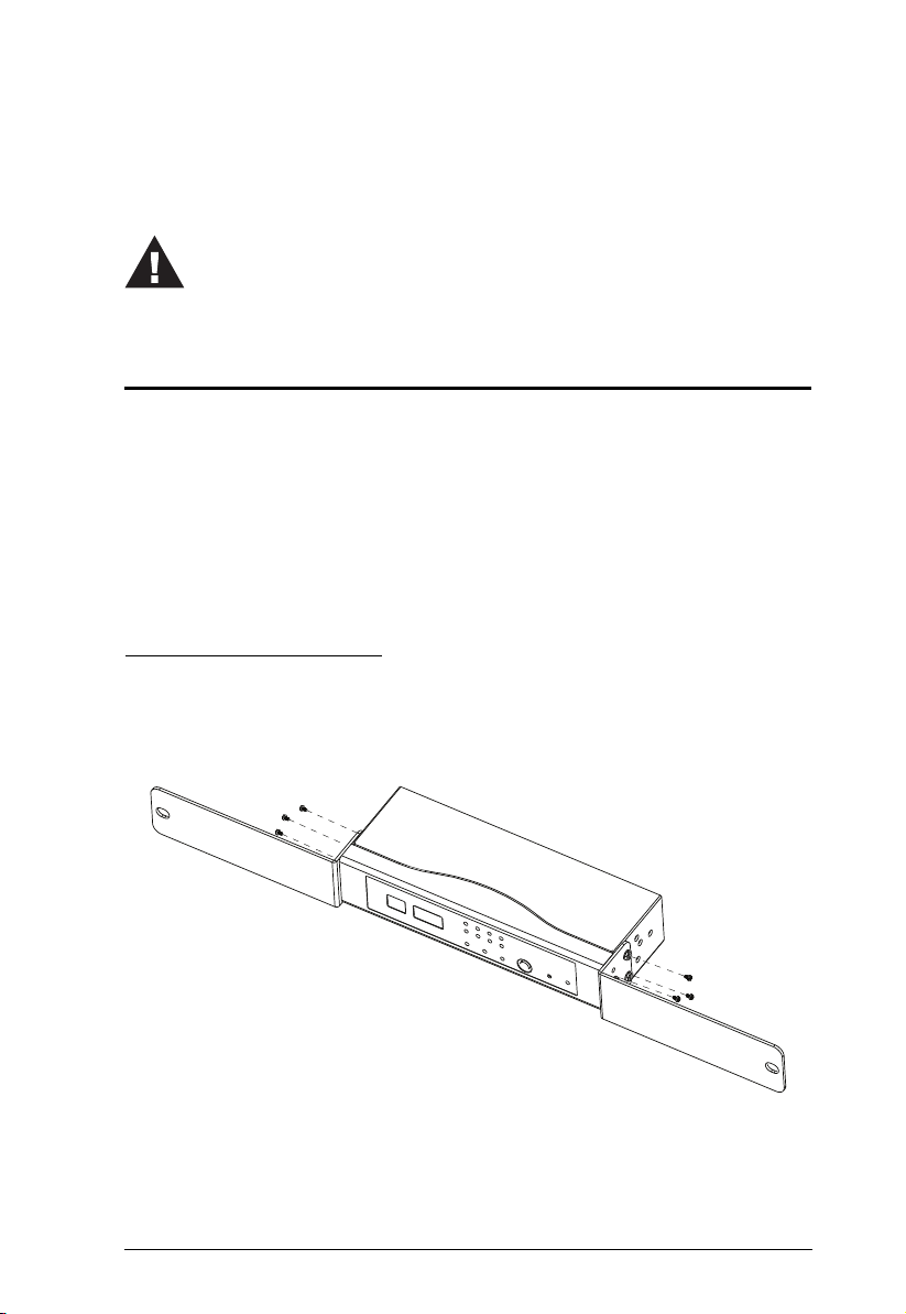
Rack Mounting - Front
1. Use 3 M3 x 8 Phillips hex head screws supplied with the rack mounting kit
to screw the rack mounting brackets into the sides near the front of the
unit.
2. Position the unit in the front of the rack and align the holes in the mounting
brackets with the holes in the rack.
11
Page 22
EC1000 / EC2004 User Manual
3. Screw the mounting brackets to the rack.
12
Page 23
Chapter 2. Hardware Setup
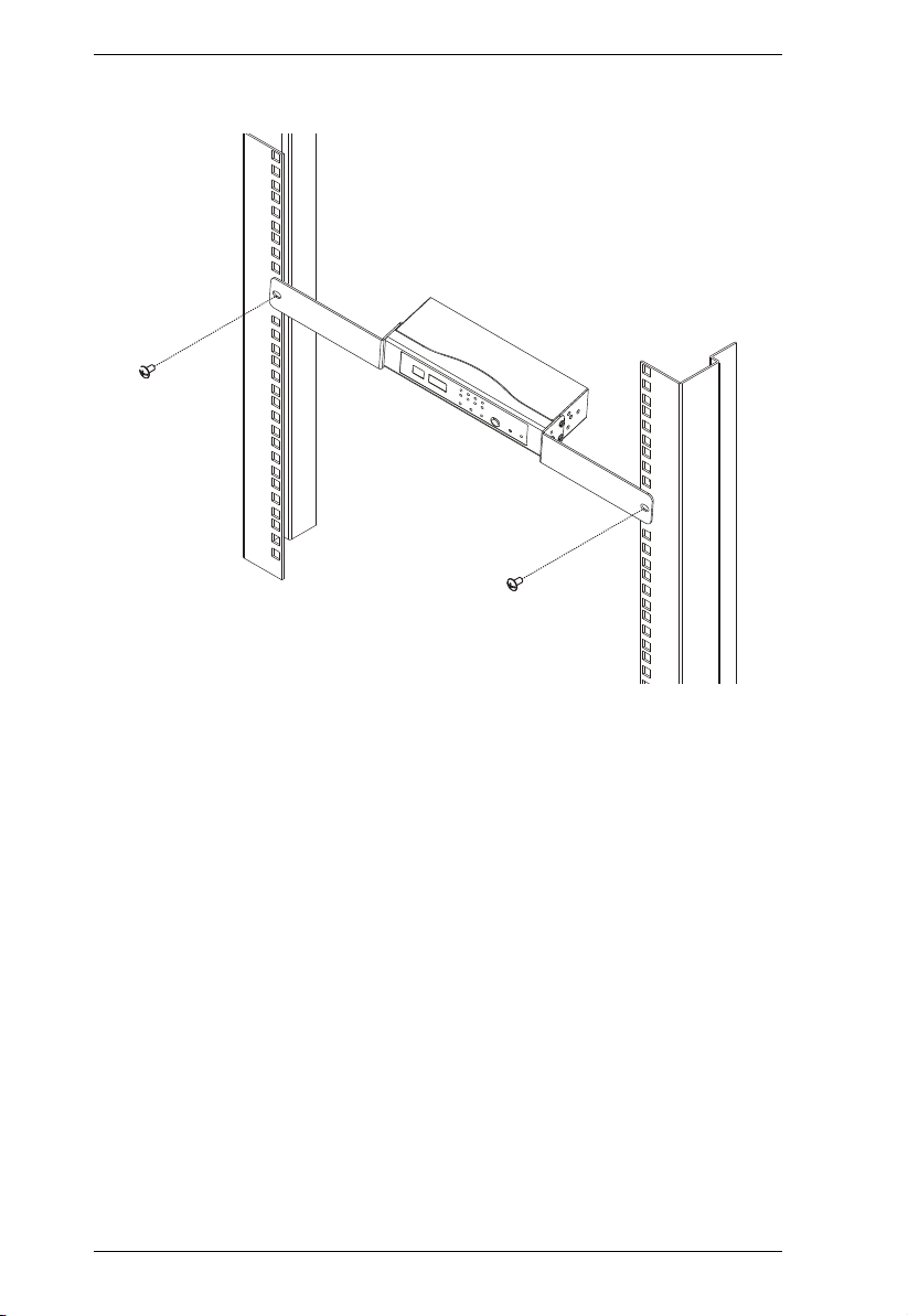
Rack Mounting - Rear
1. Use the M3 x 8 Phillips hex head screws supplied with the rack mounting
kit to screw the rack mounting brackets into the sides near the rear of the
unit.
2. Position the unit in the front of the rack and align the holes in the mounting
brackets with the holes in the rack.
3. Screw the mounting brackets to the rack.
13
Page 24
EC1000 / EC2004 User Manual
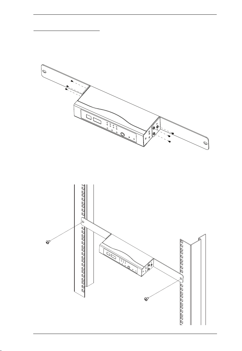
Rack Mounting - Side
1. Use 2 M3 x 8 Phillips hex head screws supplied with the rack mounting kit
to screw the rack mounting brackets onto the sides at the middle of the
unit.
2. Position the unit on the outer front of the rack and align the holes in the
mounting brackets with the holes in the rack.
3. Screw the mounting brackets to the rack.
14
Page 25

Chapter 2. Hardware Setup
Installation
To set up your EC1000 / EC2004 Energy Box installation, refer to the
installation diagram on the next page (the numbers in the diagram correspond
to the numbered steps), and do the following:
1. Use a grounding wire to ground the Energy Box by connecting one end of
the wire to its grounding terminal, and the other end of the wire to a
suitable grounded object.
Note: Do not omit this step. Proper grounding helps to prevent damage to
the unit from surges or static electricity.
2. For each Energy PDU you want to connect, use an RJ-45 cable included
with the package to connect the Energy Box to the Energy PDU.
3. Plug the cable that connects the Energy Box to the LAN, into the LAN
port.
4. (Optional) If you are using environmental sensors with your Energy Box
installation, connect them to the rear environmental sensor ports, and see
Securing the Sensors, page 17 for sensor installation.
Note: Sensors are optional. Please see Optional Accessories, page 6.
5. (Optional) If you are using a door sensor with your installation, connect it
to the 4-pin dry sensor port on the unit’s rear panel (EC2004 only), and
follow the installation instructions provided with the door sensor.
Note: See Door Sensor, page 6, for further information
6. Connect the power adapter to an AC power source.
15
Page 26
EC1000 / EC2004 User Manual
1
3
2
4
6
5
Installation Diagram
16
Page 27
Chapter 2. Hardware Setup
Securing the Sensors
Connect the sensors to the EC1000 Energy Box’s rear environmental sensor
ports and secure them using sensor mounts, tie wraps, and adhesive cable tie
holders. If you use a tie wrap to secure the sensor, tighten the tie wrap over the
recessed channel on the sensor, as shown in the following diagram:
Note: 1. The sensors shown in the above diagram are for reference purposes
only. The sensors for the EC1000 / EC2004 may look slightly
different.
2. Depending on the model and type of sensor, sensor mounts, tie wraps,
and adhesive cable tie holders may or may not be provided in the
package.
17
Page 28

EC1000 / EC2004 User Manual
This Page Intentionally Left Blank
18
Page 29

Chapter 3
Port
LED
Selection
LED
Port
Selection
Data
LED
1
1.96
Front Panel Operation
Overview
The EC1000 / EC2004 Energy Box displays real-time energy, environment,
and IP information locally via the front panel display, for monitoring at the
rack. This chapter discusses the front panel operation and monitoring.
Detailed management is done remotely over a standard TCP/IP connection via
graphical user interface (GUI) using a web browser or by ATEN's eco Sensor
software. Over-IP operation is discussed in Chapter 4, EC1000 Browser
Operation, and Chapter 5, EC2004 Browser Operation.
Front Panel Operation
The EC1000 / EC2004 front panel display is controlled by the Select
pushbutton. The Select pushbutton cycles through the energy ports,
environmental ports, and IP Address in order, displaying relevant information
for each selection in the Port LED, and Data LED displays.
The Port LED displays the port (1-4) you are viewing for each selection type:
Energy, Environment, or IP Address.
The Data LED displays relevant information about the port you are viewing.
The table on the next page explains the different information displayed for each
section.
.
19
Page 30

EC1000 / EC2004 User Manual
Selection
LED
Energy 1-4 Current Displays the power current of the
Environment 1-4 Temperature
IP 1 IP Address Displays the IP address of the EC1000
Port
Data LED Displays Data LED Description
LEDs
Energy PDU connected to Energy
Sensor port 1, 2, 3, or 4.
The data range is 0–20 A.
When an Energy port is selected the
EC1000 / EC2004 displays real-time
data for that port until you manual
switch to another port.
Displays the Temperature, Humidity,
Humidity
Differential Pressure
and Differential Pressure of the sensor
connected to Environmental Sensor
port 1, 2, 3, or 4.
When an Environmental Sensor port is
selected the Data LED will switch
between the readings, flashing a letter
first to represent the data to be
displayed, then displays the data
reading. The letter and data ranges
are:
(T) Temperature: -20–60ºC
(H) Humidity: 15–95
(D) Differential Pressure: -250–250*
After the environmental data is
displayed, the EC1000 / EC2004
automatically switches back to Energy
Sensor port 1.
*The Differential Pressure only shows
absolute values due to the displays
limitation of 3 digits.
/ EC2004, switching between each of
the four octets that make up the full IP
address.
After the IP address is displayed twice,
the EC1000 / EC2004 automatically
switches back to Energy Sensor port
1.
20
Page 31

Chapter 4
EC1000 Browser Operation
Operation Methods
The NRGence™ EC1000 Energy Box provides three methods to access and
manage your installation: Browser, eco Sensors (Energy PDU Management
Software), and SNMP. The EC2004 Browser Operation is discussed in
Chapter 5.
Note: The following sections of this chapter contain information concerning
Browser operation. For eco Sensors operation, please reference the
separate eco Sensors User Manual. The eco Sensors software and User
Manual can be downloaded from the ATEN website.
Browser
The EC1000 Energy Box can be accessed and controlled via any supported
Internet browser from any platform. See Browser Operation, page 25, and the
following sections in this chapter, for full details.
eco Sensors
The EC1000 Energy Box supports NRGence™ eco Sensors (eco PDU
Manager Software). NRGence™ eco Sensors provides you with an easy
method for managing multiple devices, offering an intuitive and user-friendly
Graphical User Interface that allows you to configure a PDU device and
monitor power status of the equipment connected to it. NRGence™ eco
Sensors can be downloaded from the ATEN website, along with a separate eco
Sensors User Manual.
SNMP
The EC1000 supports any 3rd party V1, V2, or V3 SNMP Manager Software.
SNMP Management Information Database (MIB) files for the EC1000 can be
found on the software CD provided with the EC1000 package.
21
Page 32

EC1000 / EC2004 User Manual
Browser Login
The Energy Box can be accessed via Internet browser from any OS platform.
Note: Browsers must support SSL 128 bit encryption.
To access the Energy Box, do the following:
1. Open your browser and specify the IP address of the EC1000 you want to
access in the browser's URL location bar.
Note: You can get the IP address by selecting IP from the front panel, or
see IP Address Determination, page 97, for information about
setting it up yourself.
2. If a Security Alert dialog box appears, accept the certificate – it can be
trusted. The Login page appears:
3. Provide a valid Username and Password (see First Time Setup, page 25),
and select your language.
4. Click Login to bring up the Main Page.
22
Page 33

Chapter 4. EC1000 Browser Operation
The EC1000 Main Page
After you have successfully logged in, the EC1000’s Main Page comes up with
the Access Connections page displayed:
Note: The screen depicts an Administrator’s page. Depending on a user’s type
and permissions, not all of these elements appear.
23
Page 34

EC1000 / EC2004 User Manual
Page Components
The web page screen components are described in the table, below:
No. Item Description
1 Tab Bar The tab bar contains the main operation categories.
2 Menu Bar The menu bar contains operational sub-categories
3 Sidebar The Sidebar provides a tree view listing of outlets
4 Help Connects to on-line help at the ATEN website for the
5 Logout Click this button to log out of your web session.
6 Interactive Display Panel This is your main work area. The screens that
The items that appear in the tab bar are determined
by the user’s type, and the authorization options that
were selected when the user’s account was created.
that pertain to the item selected in the tab bar. The
items that appear in the menu bar are determined by
the user’s type, and the authorization options that
were selected when the user’s account was created.
that relate to the various tab bar and menu bar
selections.
device’s configuration and operation.
appear reflect your menu choices and Sidebar
selection.
24
Page 35

Chapter 4. EC1000 Browser Operation
Browser Operation
First Time Setup
Once the Energy Box installation has been cabled up, the next task the
Administrator needs to perform involves configuring the network parameters,
changing the default Administrator login settings, and adding users.
To accomplish this you must login over the network with a browser
(See Browser Login, page 22, for details).
Note: 1. Since this is the first time you are logging in, use the default
Username: administrator; and the default Password: password. For
security purposes we recommend changing them to something unique
(see Changing the Administrator Login, page 27).
2. For remote methods of getting logged in, use the Select button from
the front panel of the EC1000 to obtain the IP address and enter it into
a web browser to access the Energy Box; or see IP Address
Determination, page 97.
After you successfully log in, the Access/Connections page appears:
Note: Operation details are discussed in Access, page 28.
25
Page 36

EC1000 / EC2004 User Manual
Network Configuration
To set up the network, do the following:
1. Click the Device Management tab.
2. The interface displays the Device Configuration page. A screen similar to
the one below appears:
3. Fill in the fields according to the information provided under Device
Configuration, page 35.
26
Page 37

Chapter 4. EC1000 Browser Operation
Changing the Administrator Login
To change the default Administrator username and password, do the following:
1. Click the User Management tab.
The User Management page has a detailed list of administrator and user
login information.
2. In the Administrator Information section, reset the name and password
fields to something unique, then click Save (at the bottom of the page.)
Note: If you forget the Administrator’s name or password, short the
mainboard jumper to restore the default Administrator account.
See Administrator Login Failure, page 101 in the Appendix for full
details.
27
Page 38

EC1000 / EC2004 User Manual
Access
Connections
When you login to the EC1000, the interface opens with its default selection of
the Access tab; on the Connections menu. The contents of the Energy Sensor
Status and Environmental Sensor Status sections are displayed in the main
panel.
28
Page 39

Chapter 4. EC1000 Browser Operation
Energy Sensor Status
The EC1000 Energy Box supports the monitoring of four Energy PDUs. The
Energy Sensor Status section allows you to view power status and set up a
power management configuration for each Energy PDU:
Energy Sensor
This field displays the Energy Sensor port number that the Energy PDU is
connected to.
Energy Sensor Name
This field displays the custom name created for the Energy sensor port
(see Configuration, page 31).
Measurement
This field displays the real-time power current reading of an Energy PDU.
Threshold Settings
This field is used to set the maximum threshold settings for the Energy
PDU’s current. If a range exceeds the maximum setting an alarm is
triggered.
29
Page 40

EC1000 / EC2004 User Manual
Environment Sensor Status
The EC1000 Energy Box supports the monitoring from four environmental
sensors*. The Environment Sensor Status section allows you to view the
status and set up environmental management configurations for each sensor
device:
Measurement
This field displays the measurement type (Temperature, Humidity,
Differential Pressure) and real-time reading of each sensor.
Threshold Settings
These fields are used to set the maximum, and minimum threshold settings
for Temperature, Humidity, and Differential Pressure. If a range falls
below the minimum setting, or exceeds the maximum setting an alarm is
triggered.
Note: Sensors are optional accessories. see Optional Accessories, page 6.
30
Page 41

Chapter 4. EC1000 Browser Operation
Configuration
The Configuration page is used to set custom names for the Energy Sensor
ports of each Energy PDU:
Each Energy Sensor port can be given a distinctive name. The maximum
number of characters is 15.
When you have finished making your changes, click Save.
31
Page 42

EC1000 / EC2004 User Manual
User Management
When you select the User Management tab the screen comes up with
Administrator Information and User Information displayed in the main panel.
The EC1000 supports one Administrator account and up to eight User
accounts.
Note: 1. Each account can support 2 login sessions.
2. The EC1000 supports a total of 3 concurrent login sessions.
Administrator Information
This section is used to set the Administrator name and password for browser
login, SNMPv3 accounts, and SNMPv1/v2c community settings. Only
Administrators can view this section. For details, see Changing the
Administrator Login, page 27.
User Information
To add a user, do the following:
1. Set the Management field to Enable.
2. Key in a name and password in the Name and Password fields.
3. Set the sensor-by-sensor permissions of the user in the Energy Sensor
field.
4. Click Save to save your settings.
Note: Correct values must be entered in both the Name and Password
fields to enable an account. For account policies see page 44.
32
Page 43

Chapter 4. EC1000 Browser Operation
The various options are explained in more detail in the following table:
Field Description
Management The Management field allows you to Enable or Disable a
user’s account:
Enable – stores the user account
Disable – disables the user account
Name From 1 to 16 characters are allowed depending on the
Password From 1 to 16 characters are allowed depending on the
Energy Sensor This field allows you to set the Energy sensor-by-sensor
Account Policy settings. See Account Policy, page 44.
Account Policy settings. See Account Policy, page 44.
permissions of the user. Click on the user/port icon to cycle
through the three permissions options, as follows:
User has complete access to this sensor port.
User has read-only access to this sensor port.
User has no access to this sensor port.
Save Click this button to save your operation or changes
33
Page 44

EC1000 / EC2004 User Manual
Log
The EC1000 keeps a record of transactions that take place on its installation,
and stores up to 128 events at one time. The System Log page provides a
powerful array of filters and functions that allow you to view and export the log
file data, as well as be informed by email of specified events as they occur. If
you need to log more then 128 events at a time, a syslog server can be used (see
Syslog Server, page 40).
The System Log Event List
Clicking on a device in the Sidebar displays its log events in the main
panel’s log event list.
Clicking the Refresh button brings the log list up to date with the latest
events.
The entry box to the right of the Refresh button lets you set the number of
events to display per page. Simply key in the number of your choice.
The top right of the main panel shows the total number of pages in the log
file, and what page you are currently viewing.
The buttons on the bottom row function as follows:
Clear – click to erase the contents of the log event list
First Page – click to go to the first page of the log event list
Previous Page – click to move to the previous page of the log event
list
Next Page – click to move to the next page of the log event list
Last Page – click to move to the last page of the log event list
Save – click to save the contents of the log event list to a Csv or Txt
type file.
34
Page 45

Chapter 4. EC1000 Browser Operation
Device Management
The Device Management page allows administrators to configure and control
overall EC1000 operations.
Device Configuration
This page provides information about the EC1000, as described in the
following sections:
General
Item Meaning
Energy Box Name This field lets you give the device a unique name. Simply delete
whatever is in the text box and key in the name of your choice.
Click Save (located at the bottom of the page) to save the new
name.
35
Page 46

EC1000 / EC2004 User Manual
Item Meaning
MAC Address This item displays the EC1000’s MAC address.
Firmware Version This item displays the current firmware version number. You can
reference it to see if there are newer versions available on the
ATEN website.
Rack Location
Name
This field lets you give the rack location a unique name for easy
reference.
Service Ports
As a security measure, if a firewall is being used, the Administrator can specify
the port numbers that the firewall will allow. If a port other than the default is
used, users must specify the port number as part of the IP address when they
login. If an invalid port number (or no port number) is specified, the EC1000
will not be found.
An explanation of the fields is given in the table below:
Field Explanation
Only HTTPs Select this button to use HTTPs service port connections.
HTTP / HTTPs Select this button to use both HTTP and HTTPs service port
HTTP The port number for a browser login. The default is 80.
HTTPS The port number for a secure browser login. The default is 443.
connections.
Note: 1. Valid entries for all of the Service Ports are from 1–65535.
2. The service ports cannot have the same value. You must set a
different value for each one.
3. If there is no firewall (on an Intranet, for example), it doesn’t matter
what these numbers are set to, since they have no effect.
36
Page 47

Chapter 4. EC1000 Browser Operation
IPv4 Configuration
The EC1000’s IPv4 IP and DNS addresses (the traditional method of
specifying IP addresses) can either be assigned dynamically (DHCP), or a fixed
IP address can be specified.
For dynamic IP address assignment, select the Obtain IP address
automatically radio button. (This is the default setting.)
To specify a fixed IP address, select the Set IP address manually radio
button and fill in the IP address with values appropriate for your network.
For automatic DNS Server address assignment, select the Obtain DNS
Server address automatically radio button.
To specify the DNS Server address manually, select the Set DNS server
address manually radio button, and fill in the addresses for the Preferred
and Alternate DNS servers with values appropriate for your network.
Note: 1. If you choose Obtain IP address automatically, when the device starts
up it waits to get its IP address from the DHCP server. If it hasn’t
obtained the address after one minute, it automatically reverts to its
factory default IP address (192.168.0.60.)
2. If the device is on a network that uses DHCP to assign network
addresses, see IP Address Determination, page 97, for information.
3. Specifying the Alternate DNS Server address is optional.
37
Page 48

EC1000 / EC2004 User Manual
Event Notification
The Event Notification section is divided into three sections: SMTP Server;
SNMP Trap Receivers; and Syslog Server. Each section is described below.
SMTP Server
To have the EC1000 email reports from the SMTP server to you, do the
following:
1. Select Enable report from the following SMTP server, and key in the IP
address of your SMTP server.
2. If your server requires authentication, select the My server requires
authentication checkbox.
3. Key in the appropriate account information in the Account Name,
Password, and From fields.
Note: Only one email address is allowed in the From fields, and it cannot
exceed 64 characters.)
4. Key in the email address (addresses) of where you want the event reports
sent to in the To field.
Note: If you are sending the report to more than one email address,
separate the addresses with a comma, or semicolon. The use of a
comma or semicolon to separate the email address will depend on
your mail servers settings.The total cannot exceed 256 characters.
38
Page 49

SNMP Trap Receivers
Chapter 4. EC1000 Browser Operation
Up to four SNMP management stations can be specified. If you want to use
SNMP trap notifications, do the following:
1. Select Enable SNMP Trap.
2. Select the type: SNMPv3, SNMPv2c, or SNMPv1.
3. For SNMPv3 key in the Receiver IP(s), User name(s), Auth-
password(s), Priv-password(s) and Service Port number(s) of the
computer(s) to be notified of SNMP trap events. The valid port range is
1–65535. The default port number is 162.
4. For SNMPv2c and SNMPv1 key in the Receiver IP(s), Community(s),
and Service Port number(s) of the computer(s) to be notified of SNMP
trap events. The valid port range is
1–65535. The default port number is 162.
39
Page 50

EC1000 / EC2004 User Manual
Syslog Server
\
To record all the events that take place on EC1000 devices and write them to
the Syslog server, do the following:
1. Check Enable Syslog Server.
2. Key in the Server IP and the Service Port of the Syslog server. The valid
port range is 1-65535. The default port number is 514.
40
Page 51

Chapter 4. EC1000 Browser Operation
Date/Time
The Date/Time dialog page sets the EC1000 Energy Box time parameters:
Set the parameters according to the information described below.
Time Zone
To establish the time zone that the EC1000 is located in, drop down the
Time Zone list and choose the city that most closely corresponds to where
it is at.
If your country or region employs Daylight Saving Time (Summer Time),
check the corresponding checkbox.
41
Page 52

EC1000 / EC2004 User Manual
Manual Input
Use this section to specify the EC1000’s date and time manually.
Click the calendar icon and click the calendar entry for the date.
Key the time into the Time field, using the HH:MM:SS (hours, minutes,
seconds) format.
Note: This section is only enabled when auto adjustment (in the Network Time
section) is disabled (the checkbox is unchecked).
As an alternative to specifying the date and time by entering them into the date
and time fields, you can click to put a check in the Sync with PC checkbox, in
which case the EC1000 will take its date and time settings from the locally
connected PC.
Network Time
To have the time automatically synchronized to a network time server, do the
following:
1. Check the Enable auto adjustment checkbox.
2. Drop down the time server list to select your preferred time server
– or –
Check the Preferred custom server IP checkbox, and key in the IP
address of the time server of your choice.
3. If you want to configure an alternate time server, check the Alternate time
server checkbox, and repeat step 2 for the alternate time server entries.
4. Key in your choice for the number of days between synchronization
procedures.
Finishing Up
When you have finished making your settings on this page, click Save.
After you have saved your changes, if you want to synchronize immediately,
click Adjust Time Now.
42
Page 53

Chapter 4. EC1000 Browser Operation
Security
The Security page controls access to the EC1000.
Login Failures
Allowed sets the number of consecutive failed login attempts that are
permitted from a remote user.
Timeout sets the amount of time a remote user must wait before
attempting to login again after exceeding the number of allowed failures.
Working Mode
If ICMP is enabled, the EC1000 Energy Box can be pinged. If it is not
enabled, the device cannot be pinged. The default is Enabled.
When you have finished making your settings on this page, click Save.
43
Page 54

EC1000 / EC2004 User Manual
Account Policy
The Account Policy section governs policies in regard to usernames and
passwords.
Check a policy and enter the required information in the appropriate fields.
Item Description
Minimum Username Length Sets the minimum number of characters required for
Minimum Password Length Sets the minimum number of characters required for
Password Must Contain At Least Checking any of these items requires users to include
Disable Duplicate Login Check this to prevent users from logging in with the
a username. Acceptable values are from 1–16.
a password. Acceptable values are from 1–16.
at least one of the specified items in their password.
Note: This policy does not affect existing user
accounts. Only new user accounts created after this
policy has been enabled, and users required to
change their passwords are affected.
same account at the same time.
44
Page 55

Chapter 4. EC1000 Browser Operation
Login String / IP Filter / Mac Filter
Login String
The Login String entry field is used to specify a login string (in addition to the
IP address) that users must include when accessing the EC1000 device with a
browser. For example:
192.168.0.126/abcdefg
The following characters are allowed:
0–9 a–z A–Z ~ ! @ $ * ( ) _ ‘ ,
The following characters are not allowed:
& ^ { } ‘ ’ < > | " % ” : / ? # \ [Space] + - = [ ] ;
Compound characters (É Ç ñ ... etc.)
Note: 1. There must be a forward slash between the IP address and the string.
2. If no login string is specified here, anyone will be able to access the
EC1000 login page using the IP address alone. This makes your
installation less secure.
3. For security purposes, we recommend that you change this string
occasionally
45
Page 56

EC1000 / EC2004 User Manual
IP Filter / MAC Filter
If any filters have been configured, they appear in the IP Filter and/or MAC
Filter list boxes.
IP and MAC Filters control access to the EC1000 based on the IP and/or MAC
addresses of the client computers attempting to connect. A maximum of 5 IP
filters and 5 MAC filters are allowed.
To enable IP and/or MAC filtering, click to put a check mark in the IP Filter
Enable and/or MAC Filter Enable checkbox.
If the Include button is checked, all the addresses within the filter range
are allowed access; all other addresses are denied access.
If the Exclude button is checked, all the addresses within the filter range
are denied access; all other addresses are allowed access.
Adding Filters
To add an IP filter, do the following:
1. Click Add. A dialog box similar to the one below appears:
2. Enter the start and end filter addresses in the dialog boxes (for example,
192.168.0.200), then click OK.
3. To filter a single IP address, key in the same IP address for the start and
end IP. To filter a continuous range of addresses, key in the last number of
the range (for example, 192.168.0.225).
4. After filling in the address, click OK.
Repeat these steps for any additional IP addresses you want to filter.
46
Page 57

Chapter 4. EC1000 Browser Operation
To add a MAC filter, do the following:
1. Click Add. A dialog box similar to the one below appears:
2. Specify the MAC address in the dialog box (for example, 001074670000),
then click OK.
Repeat these steps for any additional MAC addresses you want to filter.
IP Filter / MAC Filter Conflict
If there is a conflict between an IP filter and a MAC filter – for example, where
a computer’s IP address is allowed by the IP filter but its MAC address is
excluded by the MAC filter – then that computer’s access is blocked.
In other words, if either filter blocks a computer, then the computer is blocked,
no matter what the other filter is set to.
Modifying Filters
To modify a filter, select it in the IP Filter or MAC Filter list box and click
Modify. The Modify dialog box is similar to the Add dialog box. When it
comes up, simply delete the old address(es) and replace it with the new one(s).
Deleting Filters
To delete a filter, select it in the IP Filter or MAC Filter list box and click
Delete.
47
Page 58

EC1000 / EC2004 User Manual
Authentication & Authorization
The Authentication & Authorization page is used to set up login authentication
and authorization management from external sources.
RADIUS Settings
To allow authentication and authorization for the EC1000 device through a
RADIUS server, do the following:
1. Check Enable RADIUS.
2. Fill in the Preferred RADIUS Server IP, Preferred RADIUS Service
Port, and (optional) Alternate RADIUS Server IP and Preferred
RADIUS Service Port. The default port number for the Preferred server is
1812; the default port number for the Alternate server is 1645.
Note: Make sure that the port numbers you specify here match the port
numbers used by the RADIUS servers.
3. In the Timeout field, set the time in seconds that the EC1000 waits for a
RADIUS server reply before it times out.
4. In the Retries field, set the number of allowed retries for attempting to
connect to the RADIUS server.
5. In the Shared Secret field, key in the character string that you want to use
for authentication between the EC1000 and the RADIUS Server.
48
Page 59

Chapter 4. EC1000 Browser Operation
6. On the RADIUS server, set the entry for each user as follows:
su/xxxx
Where xxxx represents the Username given to the user when the account
was created on the EC1000. The user’s access rights are the ones assigned
for the EC1000, as well. (See User Information, page 32.)
49
Page 60

EC1000 / EC2004 User Manual
Private Certificate
When logging in over a secure (SSL) connection, a signed certificate is used to
verify that the user is logging in to the intended site. For enhanced security, the
Private Certificate section allows you to use your own private encryption key
and signed certificate, rather than the default ATEN certificate.
There are two methods for establishing your private certificate: generating a
self-signed certificate; and importing a third-party certificate authority (CA)
signed certificate.
Generating a Self-Signed Certificate
If you wish to create your own self-signed certificate, a free utility –
openssl.exe – is available for download over the web.
Obtaining a CA Signed SSL Server Certificate
For the greatest security, we recommend using a third party certificate
authority (CA) signed certificate. To obtain a third party signed certificate, go
to a CA (Certificate Authority) website to apply for an SSL certificate. After
the CA sends you the certificate and private encryption key, save them to a
convenient location on your computer.
Importing the Private Certificate
To import the private certificate, do the following:
1. Click Browse to the right of Private Key; browse to where your private
encryption key file is located; and select it.
2. Click Browse to the right of Certificate; browse to where your certificate
file is located; and select it.
3. Click Upload to complete the procedure.
Note: 1. Clicking Restore Default returns the device to using the default
ATEN certificate.
2. Both the private encryption key and the signed certificate must be
imported at the same time.
When you have finished making your settings on this page, click Save.
50
Page 61

Chapter 4. EC1000 Browser Operation
Maintenance
The Maintenance function is used to upgrade the EC1000’s firmware, and to
backup and restore the device’s configuration settings.
Firmware File
When you click the Maintenance tab, the Firmware File section is displayed
at the top of the page:
A description of the items shown in this panel are given in the table, below:
Item Description
Check Main
Firmware Version
Name Lists the name of the EC1000 Energy Box.
If you enable Check Main Firmware Version, the EC1000’s current
firmware level is compared with that of the upgrade file. If the
current version is equal to or higher than the upgrade version, a
popup message appears, to inform you of the situation and stops
the upgrade procedure.
51
Page 62

EC1000 / EC2004 User Manual
Item Description
F/W Version Displays the EC1000 ‘s current firmware version.
Filename As new versions of the firmware become available, they are
Upgrade Click this button to upgrade the firmware of the selected devices.
posted on our website and can be downloaded to a convenient
location on your computer. Click the Browse button to select the
downloaded upgrade file.
Upgrading the Firmware
To upgrade the firmware refer to the screen shot on the preceding page, and do
the following:
1. Go to our website and download the new firmware file to a convenient
location on your computer.
2. Click the Browse button; navigate to where the firmware file is located
and select it.
3. Click Upgrade to start the upgrade procedure.
If you enabled Check Main Firmware Version the current firmware
level is compared with that of the upgrade file. If the current version is
equal to or higher than the upgrade version, a popup message appears,
to inform you of the situation and stops the upgrade procedure.
If you didn't enable Check Main Firmware Version, the upgrade file
is installed without checking what its level is.
Once the upgrade completes successfully, the EC1000 resets itself.
4. Login again, and check the firmware version to be sure it is the new one.
Firmware Upgrade Recovery
Should the EC1000’s firmware upgrade procedure fail, and the device becomes
unusable, the following firmware upgrade recovery procedure will resolve the
problem:
1. Power off the device.
2. Press and hold the Reset Switch (see page 7).
3. While holding the Reset Switch in, power the switch back on.
This causes the Energy Box to use the original factory installed main firmware
version. Once the EC1000 is operational, you can try upgrading the main
firmware again.
52
Page 63

Chapter 4. EC1000 Browser Operation
Backup/Restore
Using Backup/Restore from the Maintenance tab gives you the ability to back
up the EC1000’s configuration and user profile information:
Backup
To backup the device’s settings do the following:
1. In the Password field, key in a password for the file.
Note: Entering a password is optional. If you do enter a password, make a
note of it, since you will need it to be able to restore the file.
2. Click Save.
3. When the browser asks what you want to do with the file, select Save to
disk; then save it in a convenient location.
Restore
To restore a previous backup, do the following:
1. Click Browse; navigate to the file and select it.
2. In the Password field, key in the same password that you used to save the
file.
Note: If you didn’t set a password for the file, you can omit this step.
3. Click Restore.
After the file is restored, a message appears to inform you that the procedure
succeeded, and you are automatically logged off the Energy Box.
53
Page 64

EC1000 / EC2004 User Manual
This Page Intentionally Left Blank
54
Page 65

Chapter 5
EC2004 Browser Operation
Operation Methods
The NRGence™ EC2004 Energy Box provides three methods to access and
manage your installation: Browser, eco Sensors (Energy PDU Management
Software), and SNMP. The EC1000 Browser Operation is discussed in
Chapter 4.
Note: The following sections of this chapter contain information concerning
Browser operation. For eco Sensors operation, please reference the
separate eco Sensors User Manual. The eco Sensors software and User
Manual can be downloaded from the ATEN website.
Browser
The EC2004 Energy Box can be accessed and controlled via any supported
Internet browser from any platform. See Browser Operation, page 59, and the
following sections in this chapter, for full details.
eco Sensors
The EC2004 Energy Box supports NRGence™ eco Sensors (eco PDU
Manager Software). NRGence™ eco Sensors provides you with an easy
method for managing multiple devices, offering an intuitive and user-friendly
Graphical User Interface that allows you to configure a PDU device and
monitor power status of the equipment connected to it. NRGence™ eco
Sensors can be downloaded from the ATEN website, along with a separate eco
Sensors User Manual.
SNMP
The EC2004 supports any 3rd party V1, V2, or V3 SNMP Manager Software.
SNMP Management Information Database (MIB) files for the EC2004 can be
found on the software CD provided with the EC2004 package.
55
Page 66

EC1000 / EC2004 User Manual
Browser Login
The Energy Box can be accessed via Internet browser from any OS platform.
Note: Browsers must support SSL 128 bit encryption.
To access the Energy Box, do the following:
1. Open your browser and specify the IP address of the EC2004 you want to
access in the browser's URL location bar.
Note: You can get the IP address by selecting IP from the front panel, or
see IP Address Determination, page 97, for information about
setting it up yourself.
2. If a Security Alert dialog box appears, accept the certificate – it can be
trusted. The Login page appears:
3. Provide a valid Username and Password (see First Time Setup, page 59),
and select your language.
4. Click Login to bring up the Main Page.
56
Page 67

Chapter 5. EC2004 Browser Operation
The EC2004 Main Page
After you have successfully logged in, the EC2004’s Main Page comes up with
the Access Connections page displayed:
Note: The screen depicts an Administrator’s page. Depending on a user’s type
and permissions, not all of these elements appear.
Page Components
The web page screen components are described in the table, below:
No. Item Description
1 Tab Bar The tab bar contains the main operation categories.
2 Menu Bar The menu bar contains operational sub-categories
3 Sidebar The Sidebar provides a tree view listing of outlets
The items that appear in the tab bar are determined
by the user’s type, and the authorization options that
were selected when the user’s account was created.
that pertain to the item selected in the tab bar. The
items that appear in the menu bar are determined by
the user’s type, and the authorization options that
were selected when the user’s account was created.
that relate to the various tab bar and menu bar
selections.
57
Page 68

EC1000 / EC2004 User Manual
No. Item Description
4 Help / Logout Help: Connects to on-line help at the ATEN website
5 Interactive Display Panel This is your main work area. The screens that
for the device’s configuration and operation.
Logout: Click this button to log out of your web
session.
appear reflect your menu choices and Sidebar
selection.
58
Page 69

Chapter 5. EC2004 Browser Operation
Browser Operation
First Time Setup
Once the Energy Box installation has been cabled up, the next task the
Administrator needs to perform involves configuring the network parameters,
changing the default Administrator login settings, and adding users.
To accomplish this you must login over the network with a browser
(See Browser Login, page 56, for details).
Note: 1. Since this is the first time you are logging in, use the default
Username: administrator; and the default Password: password. For
security purposes we recommend changing them to something unique
(see Changing the Administrator Login, page 61).
2. For remote methods of getting logged in, use the Select button from
the front panel of the EC2004 to obtain the IP address and enter it into
a web browser to access the Energy Box; or see IP Address
Determination, page 97.
After you successfully login, the Access/Connections page appears:
Note: Operation details are discussed in Access, page 62.
59
Page 70

EC1000 / EC2004 User Manual
Network Configuration
To set up the network, do the following:
1. Click the Setup tab.
2. The interface displays the Device Configuration page. A screen similar to
the one below appears:
3. Fill in the fields according to the information provided under Device
Configuration, page 70.
60
Page 71

Chapter 5. EC2004 Browser Operation
Changing the Administrator Login
The User page has a detailed list of administrator and user login information.
To change the default Administrator username and password, do the following:
1. Click the User tab.
2. In the Administrator Information section, reset the name and password
fields to something unique, then click Save (at the bottom of the page.)
Note: If you forget the Administrator’s name or password, short the
mainboard jumper to restore the default Administrator account.
See Administrator Login Failure, page 101 in the Appendix for details.
61
Page 72

EC1000 / EC2004 User Manual
Access
Connections
When you login to the EC2004, the interface opens with its default selection of
the Access tab; on the Connections menu. The contents of the Energy Sensor
Status and Monitor Status sections are displayed in the main panel.
62
Page 73

Chapter 5. EC2004 Browser Operation
Energy Sensor Status
The EC2004 supports the monitoring of two Energy PDU’s Amps, and two
Energy PDU’s Amps + Voltage readings. The Energy Sensor Status section
allows you to view the power status and set up power management
configurations for each Energy PDU:
Energy Sensor
This field displays the Energy Sensor port number that the Energy PDU is
connected to.
Energy Sensor Name
This field displays the custom name created for the Energy sensor port
(see Configuration, page 65).
Measurement
This field displays the real-time Current, Voltage, Power, and Power
Dissipation of the Energy PDU.
Threshold Settings
This field is used to set the minimum and maximum threshold settings for
the Energy PDU’s measurements. If a range falls below the minimum
setting, or exceeds the maximum setting an alarm is triggered.
63
Page 74

EC1000 / EC2004 User Manual
Monitor Status
The EC2004 supports PDU device level monitoring, plus monitoring via Door
and environmental sensors*. The Monitor Status section allows you to view
the status and set up environmental management configurations for each sensor
device:
Measurement
This field displays the real-time measurement from the Environmental
Sensors: (Temperature, Humidity, Differential Pressure), Door Sensor:
(Photo, Inductive Proximity, Reed), and PDU Device: (Aggregate Current,
Power, Aggregate Power Dissipation).
Threshold Settings
These fields are used to set the Door Sensor Type, and Maximum /
Minimum threshold settings for Temperature, Humidity, Differential
Pressure, and Maximum thresholds for Aggregate Current, Power, and
Aggregate Power Dissipation. If a range falls below the minimum setting,
or exceeds the maximum setting an alarm is triggered.
Note: Sensors are optional accessories. see Optional Accessories, page 6.
64
Page 75

Chapter 5. EC2004 Browser Operation
Configuration
The Configuration page, selected from the menu bar, is used to set custom
names for the Energy Sensor ports of each Energy PDU:
Each Energy Sensor port can be given a name. The maximum number of
characters is 15. When you have finished making your changes, click Save.
65
Page 76

EC1000 / EC2004 User Manual
User Management
When you select the User tab the screen comes up with Administrator
Information and User Information displayed in the main panel. The EC2004
supports one Administrator account and up to eight User accounts.
Note: 1. Each account can support 2 login sessions.
2. The EC2004 supports a total of 3 concurrent login sessions.
Administrator Information
This section is used to set the Administrator name and password for browser
login, SNMPv3 accounts, and SNMPv1/v2c community settings. Only
Administrators can view this section. For details, see Changing the
Administrator Login, page 61.
User Information
To add a user, do the following:
1. Set the Management field to Enable.
2. Key in a name and password in the Name and Password fields.
3. Set the sensor-by-sensor permissions of the user in the Energy Sensor
field.
4. Click Save to save your settings.
Note: Correct values must be entered in both the Name and Password
fields to enable an account. For account policies see page 80.
66
Page 77

Chapter 5. EC2004 Browser Operation
The various options are explained in more detail in the following table:
Field Description
Management The Management field allows you to Enable or Disable a
user’s account:
Enable – stores the user account
Disable – disables the user account
Name From 1 to 16 characters are allowed depending on the
Password From 1 to 16 characters are allowed depending on the
Energy Sensor This field allows you to set the Energy sensor-by-sensor
Account Policy settings. See Account Policy, page 80.
Account Policy settings. See Account Policy, page 80.
permissions of the user. Click on the user/port icon to cycle
through the three permissions options, as follows:
User has complete access to this sensor port.
User has read-only access to this sensor port.
User has no access to this sensor port.
Save Click this button to save your operation or changes
67
Page 78

EC1000 / EC2004 User Manual
Log
The EC2004 keeps a record of transactions that take place on its installation,
and stores up to 128 events at one time. The System Log page provides a
powerful array of filters and functions that allow you to view and export the log
file data, as well as be informed by email of specified events as they occur. If
you need to log more then 128 events at a time, a syslog server can be used (see
Syslog Server, page 76). In addition, from the Notification Settings page, you
can configure notification settings to be sent via Syslog, E-mail, or SNMP.
The System Log Event List
Clicking on a device in the Sidebar displays its log events in the main
panel’s log event list.
Clicking the Refresh button brings the log list up to date with the latest
events.
The entry box to the right of the Refresh button lets you set the number of
events to display per page. Simply key in the number of your choice.
The top right of the main panel shows the total number of pages in the log
file, and what page you are currently viewing.
The buttons on the bottom row function as follows:
Clear – click to erase the contents of the log event list
First Page – click to go to the first page of the log event list
Previous Page – click to move to the previous page of the log event
list
68
Page 79

Chapter 5. EC2004 Browser Operation
Next Page – click to move to the next page of the log event list
Last Page – click to move to the last page of the log event list
Save – click to save the contents of the log event list to a Csv or Txt
type file.
Notification Settings
The Notification Settings page lets you decide which events trigger a
notification, and how the notifications are sent out:
Notifications can be sent via E-mail, SNMP, or written to the SysLog file, or
any combination of the three. A check mark (
√ ) indicates that notification of
the event is permitted for the method specified in the column heading; an
empty box indicates that notification is not restricted.
To view all log options, you can expand the Event Lists: Enable all system
events, Enable all Authentication events, Enable all User Management
events, or Enable all Device Management events, using icon below.
Note: In any of the columns, you can select the top heading to select a group
of events. Clicking permit/restrict on a group heading causes all of them
to change in unison.
69
Page 80

EC1000 / EC2004 User Manual
Setup
The Setup page allows administrators to set the EC2004’s device
configurations and security.
Device Configuration
This page provides information about the EC2004, as described in the
following sections:
General
Item Meaning
Energy Box Name This field lets you give the device a unique name. Simply delete
whatever is in the text box and key in the name of your choice.
Click Save (located at the bottom of the page) to save the new
name.
70
Page 81

Chapter 5. EC2004 Browser Operation
Item Meaning
MAC Address This item displays the EC2004’s MAC address.
Firmware Version This item displays the current firmware version number. You can
reference it to see if there are newer versions available on the
ATEN website.
Rack Location
Name
This field lets you give the rack location a unique name for easy
reference.
Service Ports
As a security measure, if a firewall is being used, the Administrator can specify
the port numbers that the firewall will allow. If a port other than the default is
used, users must specify the port number as part of the IP address when they
login. If an invalid port number (or no port number) is specified, the EC2004
will not be found.
An explanation of the fields is given in the table below:
Field Explanation
Only HTTPs Select this button to only use HTTPs service port connections.
HTTP / HTTPs Select this button to use both HTTP and HTTPs service port
connections.
HTTP The port number for a browser login. The default is 80.
HTTPS The port number for a secure browser login. The default is 443.
Note: 1. Valid entries for all of the Service Ports are from 1–65535.
2. The service ports cannot have the same value. You must set a
different value for each one.
3. If there is no firewall (on an Intranet, for example), it doesn’t matter
what these numbers are set to, since they have no effect.
71
Page 82

EC1000 / EC2004 User Manual
IPv4 Configuration
The EC2004’s IPv4 IP and DNS addresses (the traditional method of
specifying IP addresses) can either be assigned dynamically (DHCP), or a fixed
IP address can be specified.
For dynamic IP address assignment, select the Obtain IP address
automatically radio button. (This is the default setting.)
To specify a fixed IP address, select the Set IP address manually radio
button and fill in the IP address with values appropriate for your network.
For automatic DNS Server address assignment, select the Obtain DNS
Server address automatically radio button.
To specify the DNS Server address manually, select the Set DNS server
address manually radio button, and fill in the addresses for the Preferred
and Alternate DNS servers with values appropriate for your network.
Note: 1. If you choose Obtain IP address automatically, when the device starts
up it waits to get its IP address from the DHCP server. If it hasn’t
obtained the address after one minute, it automatically reverts to its
factory default IP address (192.168.0.60.)
2. If the device is on a network that uses DHCP to assign network
addresses, and you need to ascertain its IP address, see IP Address
Determination, page 97, for information.
3. Specifying the Alternate DNS Server address is optional.
72
Page 83

Chapter 5. EC2004 Browser Operation
IPv6 Configuration
IPv6 is the new (128-bit) format for specifying IP addresses* (See IPv6,
page 99 for further information).
Note: At present, the EC2004 does not support IPv6 but we intend to enable
this feature in the near future. For more information, please check our
website for the latest EC2004 firmware updates.
For auto IP address assignment, select the Enable autoconfiguration radio
button.
To specify a fixed IP address, select the Set configuration manually radio
button and fill in the IP address with values appropriate for your network.
For automatic DNS Server address assignment, select the Use DHCPv6 to
obtain DNS Server Addresses radio button.
To specify the DNS Server address manually, select the Set DNS server
address manually radio button, and fill in the addresses for the Preferred
and Alternate DNS servers with values appropriate for your network.
Note: 1. If the device is on a network that uses DHCP to assign network
addresses, and you need to ascertain its IP address, see IP Address
Determination, page 97, for information.
2. Specifying the Alternate DNS Server address is optional.
73
Page 84

EC1000 / EC2004 User Manual
Event Notification
The Event Notification section is divided into three sections: SMTP Server;
SNMP Trap Receivers; and Syslog Server. Each section is described below.
SMTP Server
To have the EC2004 email reports from the SMTP server to you, do the
following:
1. Select Enable report from the following SMTP Server, and key in the
IP address of your SMTP server.
2. If your server requires authentication, select the My server requires
authentication checkbox.
3. Key in the appropriate account information in the Account Name,
Password, and From fields.
Note: Only one email address is allowed in the From fields, and it cannot
exceed 64 characters.)
4. Key in the email address (addresses) of where you want the event reports
sent to in the To field.
Note: If you are sending the report to more than one email address,
separate the addresses with a comma or semicolon. The use of a
comma or semicolon to separate the email address will depend on
your mail servers settings.The total cannot exceed 256 characters.
74
Page 85

SNMP Trap Receivers
Chapter 5. EC2004 Browser Operation
Up to four SNMP management stations can be specified. If you want to use
SNMP trap notifications, do the following:
1. Check Enable SNMP Trap.
2. Select the type: SNMPv3, SNMPv2c, or SNMPv1.
3. For SNMPv3 key in the Receiver IP(s), User name(s), Auth-
password(s), Priv-password(s) and Service Port number(s) of the
computer(s) to be notified of SNMP trap events. The valid port range is
1–65535. The default port number is 162.
4. For SNMPv2c and SNMPv1 key in the Receiver IP(s), Community(s),
and Service Port number(s) of the computer(s) to be notified of SNMP
trap events. The valid port range is
1–65535. The default port number is 162.
75
Page 86

EC1000 / EC2004 User Manual
Syslog Server
To record all the events that take place on EC2004 devices and write them to
the Syslog server, do the following:
1. Check Enable Syslog Server.
2. Key in the Server IP and the Service Port of the Syslog server. The valid
port range is 1-65535. The default port number is 514.
76
Page 87

Chapter 5. EC2004 Browser Operation
Date/Time
The Date/Time dialog page sets the EC2004 time parameters:
Set the parameters according to the information described below.
Time Zone
To establish the time zone that the EC2004 is located in, drop down the
Time Zone list and choose the city that most closely corresponds to where
it is at.
If your country or region employs Daylight Saving Time (Summer Time),
check the corresponding checkbox.
77
Page 88

EC1000 / EC2004 User Manual
Manual Input
Use this section to specify the EC2004’s date and time manually.
Click the calendar icon and click the calendar entry for the date.
Key the time into the Time field, using the HH:MM:SS (hours, minutes,
seconds) format.
Note: This section is only enabled when auto adjustment (in the Network Time
section) is disabled (the checkbox is unchecked).
As an alternative to specifying the date and time by entering them into the date
and time fields, you can click to put a check in the Sync with PC checkbox, in
which case the EC2004 will take its date and time settings from the locally
connected PC.
Network Time
To have the time automatically synchronized to a network time server, do the
following:
1. Check the Enable auto adjustment checkbox.
2. Drop down the time server list to select your preferred time server
– or –
Check the Preferred custom server IP checkbox, and key in the IP
address of the time server of your choice.
3. If you want to configure an alternate time server, check the Alternate time
server checkbox, and repeat step 2 for the alternate time server entries.
4. Key in your choice for the number of days between synchronization
procedures.
Finishing Up
When you have finished making your settings on this page, click Save.
After you have saved your changes, if you want to synchronize immediately,
click Adjust Time Now.
78
Page 89

Chapter 5. EC2004 Browser Operation
Security
The Security page controls access to the EC2004.
Login Failures
Allowed sets the number of consecutive failed login attempts that are
permitted from a remote user.
Timeout sets the amount of time a remote user must wait before
attempting to login again after exceeding the number of allowed failures.
Working Mode
If ICMP is enabled, the EC1000 Energy Box can be pinged. If it is not
enabled, the device cannot be pinged. The default is Enabled.
79
Page 90

EC1000 / EC2004 User Manual
Account Policy
The Account Policy section governs policies in regard to usernames and
passwords.
Check a policy and enter the required information in the appropriate fields.
Item Description
Minimum Username Length Sets the minimum number of characters required for
a username. Acceptable values are from 1–16.
Minimum Password Length Sets the minimum number of characters required for
Password Must Contain At Least Checking any of these items requires users to include
Disable Duplicate Login Check this to prevent users from logging in with the
a password. Acceptable values are from 1–16.
at least one of the specified items in their password.
Note: This policy does not affect existing user
accounts. Only new user accounts created after this
policy has been enabled, and users required to
change their passwords are affected.
same account at the same time.
80
Page 91

Chapter 5. EC2004 Browser Operation
Login String / IP Filter / Mac Filter
Login String
The Login String entry field is used to specify a login string (in addition to the
IP address) that users must include when accessing the EC2004 device with a
browser. For example:
192.168.0.126/abcdefg
The following characters are allowed:
0–9 a–z A–Z ~ ! @ $ * ( ) _ ‘ ,
The following characters are not allowed:
& ^ { } ‘ ’ < > | " % ” : / ? # \ [Space] + - = [ ] ;
Compound characters (É Ç ñ ... etc.)
Note: 1. There must be a forward slash between the IP address and the string.
2. If no login string is specified here, anyone will be able to access the
EC2004 login page using the IP address alone. This makes your
installation less secure.
3. For security purposes, we recommend that you change this string
occasionally
81
Page 92

EC1000 / EC2004 User Manual
IP Filter / MAC Filter
If any filters have been configured, they appear in the IP Filter and/or MAC
Filter list boxes.
IP and MAC Filters control access to the EC2004 based on the IP and/or MAC
addresses of the client computers attempting to connect. A maximum of 5 IP
filters and 5 MAC filters are allowed.
To enable IP and/or MAC filtering, click to put a check mark in the IP Filter
Enable and/or MAC Filter Enable checkbox.
If the Include button is checked, all the addresses within the filter range
are allowed access; all other addresses are denied access.
If the Exclude button is checked, all the addresses within the filter range
are denied access; all other addresses are allowed access.
Adding Filters
To add an IP filter, do the following:
1. Click Add. A dialog box similar to the one below appears:
2. Enter the start and end filter addresses in the dialog boxes (for example,
192.168.0.200), then click OK.
3. To filter a single IP address, key in the same IP address for the start and
end IP. To filter a continuous range of addresses, key in the last number of
the range (for example, 192.168.0.225).
4. After filling in the address, click OK.
Repeat these steps for any additional IP addresses you want to filter.
82
Page 93

Chapter 5. EC2004 Browser Operation
To add a MAC filter, do the following:
1. Click Add. A dialog box similar to the one below appears:
2. Specify the MAC address in the dialog box (for example, 001074670000),
then click OK.
Repeat these steps for any additional MAC addresses you want to filter.
IP Filter / MAC Filter Conflict
If there is a conflict between an IP filter and a MAC filter – for example, where
a computer’s IP address is allowed by the IP filter but its MAC address is
excluded by the MAC filter – then that computer’s access is blocked.
In other words, if either filter blocks a computer, then the computer is blocked,
no matter what the other filter is set to.
Modifying Filters
To modify a filter, select it in the IP Filter or MAC Filter list box and click
Modify. The Modify dialog box is similar to the Add dialog box. When it
comes up, simply delete the old address(es) and replace it with the new one(s).
Deleting Filters
To delete a filter, select it in the IP Filter or MAC Filter list box and click
Delete.
83
Page 94

EC1000 / EC2004 User Manual
Authentication & Authorization
The Authentication & Authorization page is used to set up login authentication
and authorization management from external sources.
RADIUS Settings
To allow authentication and authorization for the EC2004 device through a
RADIUS server, do the following:
1. Check Enable RADIUS.
2. Fill in the Preferred RADIUS Server IP, Preferred RADIUS Service
Port, and (optional) Alternate RADIUS Server IP and Preferred
RADIUS Service Port. The default port number for the Preferred server is
1812; the default port number for the Alternate server is 1645.
Note: Make sure that the port numbers you specify here match the port
numbers used by the RADIUS servers.
3. In the Timeout field, set the time in seconds that the EC2004 waits for a
RADIUS server reply before it times out.
4. In the Retries field, set the number of allowed retries for attempting to
connect to the RADIUS server.
5. In the Shared Secret field, key in the character string that you want to use
for authentication between the EC2004 and the RADIUS Server.
84
Page 95

Chapter 5. EC2004 Browser Operation
6. On the RADIUS server, set the entry for each user as follows:
su/xxxx
Where xxxx represents the Username given to the user when the account
was created on the EC2004. The user’s access rights are the ones assigned
for the EC2004, as well. (See User Information, page 66.)
85
Page 96

EC1000 / EC2004 User Manual
Private Certificate
When logging in over a secure (SSL) connection, a signed certificate is used to
verify that the user is logging in to the intended site. For enhanced security, the
Private Certificate section allows you to use your own private encryption key
and signed certificate, rather than the default ATEN certificate.
There are two methods for establishing your Private Certificate: generating a
self-signed certificate; and importing a third-party certificate authority (CA)
signed certificate.
Generating a Self-Signed Certificate
If you wish to create your own self-signed certificate, a free utility –
openssl.exe – is available for download over the web.
Obtaining a CA Signed SSL Server Certificate
For the greatest security, we recommend using a third party certificate
authority (CA) signed certificate. To obtain a third party signed certificate, go
to a CA (Certificate Authority) website to apply for an SSL certificate. After
the CA sends you the certificate and private encryption key, save them to a
convenient location on your computer.
Importing the Private Certificate
To import the private certificate, do the following:
1. Click Browse to the right of Private Key; browse to where your private
encryption key file is located; and select it.
2. Click Browse to the right of Certificate; browse to where your certificate
file is located; and select it.
3. Click Upload to complete the procedure.
Note: 1. Clicking Restore Default returns the device to using the default
ATEN certificate.
2. Both the private encryption key and the signed certificate must be
imported at the same time.
When you have finished making your settings on this page, click Save.
86
Page 97

Chapter 5. EC2004 Browser Operation
PDU
The PDU function is used to upgrade the EC2004’s firmware, and to backup
and restore the device’s configuration settings.
Firmware File
When you click the PDU tab, Firmware Upgrade File is displayed at the top,
which looks similar to the one below:
A description of the items shown in this panel are given in the table, below:
Item Description
Check Main
Firmware Version
Energy Box Name Lists the name of the EC2004 Energy Box.
If you enable Check Main Firmware Version, the EC2004’s current
firmware level is compared with that of the upgrade file. If the
current version is equal to or higher than the upgrade version, a
popup message appears, to inform you of the situation and stops
the upgrade procedure.
87
Page 98

EC1000 / EC2004 User Manual
Item Description
F/W Version Displays the EC2004 ‘s current firmware version.
Filename As new versions of the firmware become available, they are
Upgrade Click this button to upgrade the firmware of the selected devices.
posted on our website and can be downloaded to a convenient
location on your computer. Click the Browse button to select the
downloaded upgrade file.
Upgrading the Firmware
To upgrade the firmware refer to the screen shot on the preceding page, and do
the following:
1. Go to our website and download the new firmware file to a convenient
location on your computer.
2. Click the Browse button; navigate to where the firmware file is located
and select it.
3. Click Upgrade to start the upgrade procedure.
If you enabled Check Main Firmware Version the current firmware
level is compared with that of the upgrade file. If the current version is
equal to or higher than the upgrade version, a popup message appears,
to inform you of the situation and stops the upgrade procedure.
If you didn't enable Check Main Firmware Version, the upgrade file
is installed without checking what its level is.
Once the upgrade completes successfully, the EC2004 resets itself.
4. Log in again, and check the firmware version to be sure it is the new one.
Firmware Upgrade Recovery
Should the EC2004’s firmware upgrade procedure fail, and the device becomes
unusable, the following firmware upgrade recovery procedure will resolve the
problem:
1. Power off the device.
2. Press and hold the Reset Switch (see page 7).
3. While holding the Reset Switch in, power the switch back on.
This causes the switch to use the original factory installed main firmware
version. Once the switch is operational, you can try upgrading the main
firmware again.
88
Page 99

Chapter 5. EC2004 Browser Operation
Backup/Restore
Using Backup/Restore from the PDU tab gives you the ability to back up the
EC2004’s configuration and user profile information:
Backup
To backup the device’s settings do the following:
1. In the Password field, key in a password for the file.
Note: Entering a password is optional. If you do enter a password, make a
note of it, since you will need it to be able to restore the file.
2. Click Save.
3. When the browser asks what you want to do with the file, select Save to
disk; then save it in a convenient location.
Restore
To restore a previous backup, do the following:
1. Click Browse; navigate to the file and select it.
2. In the Password field, key in the same password that you used to save the
file.
Note: If you didn’t set a password for the file, you can omit this step.
3. Click Restore.
After the file is restored, a message appears to inform you that the procedure
succeeded, and you are automatically logged off the Energy Box.
89
Page 100

EC1000 / EC2004 User Manual
This Page Intentionally Left Blank
90
 Loading...