


8/16-Port USB 3.0 4K HDMI KVM Switch
CS18208 / CS18216
8/16-Port USB 3.0
4K HDMI KVM Switch
User Manual
CS18208 / CS18216
User Manual
www.aten.com

CS18208 / CS18216 User Manual
Compliance Statements
FEDERAL COMMUNICATIONS COMMISSION INTERFERENCE
STATEMENT
This equipment has been tested and found to comply with the limits for a Class
A digital device, pursuant to Part 15 of the FCC Rules. These limits are
designed to provide reasonable protection against harmful interference when
the equipment is operated in a commercial environment. This equipment
ge nerates, u ses, and ca n rad iate radio frequen cy energy a nd, if not installed and
used in accordance with the instruction manual, may cause harmful
interference to radio communications. Operation of this equipment in a
residential area is likely to cause harmful interference in which case the user
will be required to correct the interference at his own expense.
The device complies with Part 15 of the FCC Rules. Operation is subject to the
following two conditions: (1) this device may not cause harmful interference,
and (2) this device must accept any interference received, including
interference that may cause undesired operation.
FCC Caution
Any changes or modifications not expressly approved by the party responsible
for compliance could void the user's authority to operate this equipment.
Warning
Operation of this equipment in a residential environment could cause radio
interference.
Achtung
Der Gebrauch dieses Geräts in Wohnumgebung kann Funkstörungen
verursachen.
KCC Statement
ii

CS18208 / CS18216 User Manual
Industry Canada Statement
This Class A digital apparatus complies with Canadian ICES-003.
HDMI Trademark Statement
The terms HDMI, HDMI High-Definition Multimedia Interface, and the
HDMI Logo are trademarks or registered trademarks of HDMI Licensing
Administrator, Inc.
RoHS
This product is RoHS compliant.
iii

CS18208 / CS18216 User Manual
User Information
Online Registration
Be sure to register your product at our online support center:
International http://eservice.aten.com
Telephone Support
For telephone support, call this number:
International 886-2-8692-6959
China 86-400-810-0-810
Japan 81-3-5615-5811
Korea 82-2-467-6789
North America 1-888-999-ATEN ext 4988
1-949-428-1111
User Notice
All information, documentation, and specifications contained in this manual
are subject to change without prior notification by the manufacturer. The
manufacturer makes no representations or warranties, either expressed or
implied, with respect to the contents hereof and specifically disclaims any
warranties as to merchantability or fitness for any particular purpose. Any of
the manufacturer's software described in this manual is sold or licensed as is.
Should the programs prove defective following their purchase, the buyer (and
not the manufacturer, its distributor, or its dealer), assumes the entire cost of all
necessary servicing, repair and any incidental or consequential damages
resulting from any defect in the software.
The manufacturer of this system is not responsible for any radio and/or TV
interference caused by unauthorized modifications to this device. It is the
responsibility of the user to correct such interference.
The manufacturer is not responsible for any damage incurred in the operation
of this system if the correct operational voltage setting was not selected prior
to operation. PLEASE VERIFY THAT THE VOLTAGE SETTING IS
CORRECT BEFORE USE.
iv

CS18208 / CS18216 User Manual
Product Information
For information about all ATEN products and how they can help you connect
without limits, visit ATEN on the Web or contact an ATEN Authorized
Reseller. Visit ATEN on the Web for a list of locations and telephone numbers:
International http://www.aten.com
North America http://www.aten-usa.com
v

CS18208 / CS18216 User Manual
Package Contents
Check to make sure that all the components are in working order. If you
encounter any problem, please contact your dealer.
1 CS18208 / CS18216 8/16-Port USB 3.0 4K HDMI KVM Switch with
Rack Mounting Kit
2 HDMI cables
2 USB 3.0 cables
2 audio cables
1 firmware upgrade cable
1 foot pad set (4 pcs)
1 power adapter
1 user instructions
vi

CS18208 / CS18216 User Manual
Contents
Compliance Statements . . . . . . . . . . . . . . . . . . . . . . . . . . . . . . . . . . . . . . . ii
User Information . . . . . . . . . . . . . . . . . . . . . . . . . . . . . . . . . . . . . . . . . . . . iv
Online Registration . . . . . . . . . . . . . . . . . . . . . . . . . . . . . . . . . . . . . . . iv
Telephone Support . . . . . . . . . . . . . . . . . . . . . . . . . . . . . . . . . . . . . . . iv
User Notice . . . . . . . . . . . . . . . . . . . . . . . . . . . . . . . . . . . . . . . . . . . . . iv
Product Information . . . . . . . . . . . . . . . . . . . . . . . . . . . . . . . . . . . . . . . . . . v
Package Contents . . . . . . . . . . . . . . . . . . . . . . . . . . . . . . . . . . . . . . . . . . vi
Contents . . . . . . . . . . . . . . . . . . . . . . . . . . . . . . . . . . . . . . . . . . . . . . . . . . vii
About this Manual . . . . . . . . . . . . . . . . . . . . . . . . . . . . . . . . . . . . . . . . . . xi
Conventions . . . . . . . . . . . . . . . . . . . . . . . . . . . . . . . . . . . . . . . . . . . . xii
1. Introduction
Overview . . . . . . . . . . . . . . . . . . . . . . . . . . . . . . . . . . . . . . . . . . . . . . . . . . . 1
Features . . . . . . . . . . . . . . . . . . . . . . . . . . . . . . . . . . . . . . . . . . . . . . . . . . .2
Requirements . . . . . . . . . . . . . . . . . . . . . . . . . . . . . . . . . . . . . . . . . . . . . . .4
Console . . . . . . . . . . . . . . . . . . . . . . . . . . . . . . . . . . . . . . . . . . . . . . . .4
Computers . . . . . . . . . . . . . . . . . . . . . . . . . . . . . . . . . . . . . . . . . . . . . .4
Cables . . . . . . . . . . . . . . . . . . . . . . . . . . . . . . . . . . . . . . . . . . . . . . . . . 5
Operating Systems . . . . . . . . . . . . . . . . . . . . . . . . . . . . . . . . . . . . . . . .5
Components . . . . . . . . . . . . . . . . . . . . . . . . . . . . . . . . . . . . . . . . . . . . . . . .6
Front View CS18208 . . . . . . . . . . . . . . . . . . . . . . . . . . . . . . . . . . . . . .6
Front View CS18216 . . . . . . . . . . . . . . . . . . . . . . . . . . . . . . . . . . . . . . .6
Rear View CS18208 . . . . . . . . . . . . . . . . . . . . . . . . . . . . . . . . . . . . . . .9
Rear View CS18216 . . . . . . . . . . . . . . . . . . . . . . . . . . . . . . . . . . . . . . .9
2. Hardware Setup
Overview . . . . . . . . . . . . . . . . . . . . . . . . . . . . . . . . . . . . . . . . . . . . . . . . . . 11
Installation Types . . . . . . . . . . . . . . . . . . . . . . . . . . . . . . . . . . . . . . . . 11
Before You Begin . . . . . . . . . . . . . . . . . . . . . . . . . . . . . . . . . . . . . . . . . . .11
Stacking and Rack Mounting . . . . . . . . . . . . . . . . . . . . . . . . . . . . . . . . . .12
Stacking . . . . . . . . . . . . . . . . . . . . . . . . . . . . . . . . . . . . . . . . . . . . . . .12
Rack Mounting – Front . . . . . . . . . . . . . . . . . . . . . . . . . . . . . . . . . . . . 13
Rack Mounting – Rear . . . . . . . . . . . . . . . . . . . . . . . . . . . . . . . . . . . .15
Single Stage Installation . . . . . . . . . . . . . . . . . . . . . . . . . . . . . . . . . . . . . . 17
Single Stage Installation Diagram . . . . . . . . . . . . . . . . . . . . . . . . . . . .18
Two Stage Cascade . . . . . . . . . . . . . . . . . . . . . . . . . . . . . . . . . . . . . . . . .19
Two Stage Installation Diagram . . . . . . . . . . . . . . . . . . . . . . . . . .21
Three Stage Cascade . . . . . . . . . . . . . . . . . . . . . . . . . . . . . . . . . . . . . . .22
Three Stage Installation Diagram . . . . . . . . . . . . . . . . . . . . . . . . .23
Multi-display Installation . . . . . . . . . . . . . . . . . . . . . . . . . . . . . . . . . . . . . . 24
Cable Connections for Multi-display Installation . . . . . . . . . . . . . . . . .24
Multi-display Installation Diagram . . . . . . . . . . . . . . . . . . . . . . . . . . . .25
Grouping Ports into “Vertical” Channels . . . . . . . . . . . . . . . . . . . . . . .26
vii

CS18208 / CS18216 User Manual
Channels Diagram . . . . . . . . . . . . . . . . . . . . . . . . . . . . . . . . . . . . . . . 26
3. Basic Operation
Hot Plugging . . . . . . . . . . . . . . . . . . . . . . . . . . . . . . . . . . . . . . . . . . . . . . . 27
Hot Plugging KVM Ports . . . . . . . . . . . . . . . . . . . . . . . . . . . . . . . . . . . 27
Hot Plugging Console Ports . . . . . . . . . . . . . . . . . . . . . . . . . . . . . . . . 27
Port Selection . . . . . . . . . . . . . . . . . . . . . . . . . . . . . . . . . . . . . . . . . . . . . 28
Manual Port Switching . . . . . . . . . . . . . . . . . . . . . . . . . . . . . . . . . . . . 28
Port ID Numbering . . . . . . . . . . . . . . . . . . . . . . . . . . . . . . . . . . . . . . . . . . 28
Powering Off and Restarting . . . . . . . . . . . . . . . . . . . . . . . . . . . . . . . . . . 29
4. OSD Operation
OSD Overview . . . . . . . . . . . . . . . . . . . . . . . . . . . . . . . . . . . . . . . . . . . . . 31
Manufacturing Number . . . . . . . . . . . . . . . . . . . . . . . . . . . . . . . . . . . . 31
OSD Login. . . . . . . . . . . . . . . . . . . . . . . . . . . . . . . . . . . . . . . . . . . . . . 31
OSD Hotkey . . . . . . . . . . . . . . . . . . . . . . . . . . . . . . . . . . . . . . . . . . . . 32
OSD Main Screen . . . . . . . . . . . . . . . . . . . . . . . . . . . . . . . . . . . . . . . . 32
OSD Main Screen Headings. . . . . . . . . . . . . . . . . . . . . . . . . . . . . . . . 33
OSD Navigation . . . . . . . . . . . . . . . . . . . . . . . . . . . . . . . . . . . . . . . . . 33
OSD Functions . . . . . . . . . . . . . . . . . . . . . . . . . . . . . . . . . . . . . . . . . . . . 34
F1: Go To . . . . . . . . . . . . . . . . . . . . . . . . . . . . . . . . . . . . . . . . . . . . . . 35
F2: List . . . . . . . . . . . . . . . . . . . . . . . . . . . . . . . . . . . . . . . . . . . . . . . . 36
F3: Set . . . . . . . . . . . . . . . . . . . . . . . . . . . . . . . . . . . . . . . . . . . . . . . . 37
F4: Admin . . . . . . . . . . . . . . . . . . . . . . . . . . . . . . . . . . . . . . . . . . . . . . 39
F5: SKP . . . . . . . . . . . . . . . . . . . . . . . . . . . . . . . . . . . . . . . . . . . . . . . 43
F6: BRC . . . . . . . . . . . . . . . . . . . . . . . . . . . . . . . . . . . . . . . . . . . . . . . 44
F7: SCAN . . . . . . . . . . . . . . . . . . . . . . . . . . . . . . . . . . . . . . . . . . . . . . 45
F8: Logout . . . . . . . . . . . . . . . . . . . . . . . . . . . . . . . . . . . . . . . . . . . . . 46
5. Hotkey Operation
Overview. . . . . . . . . . . . . . . . . . . . . . . . . . . . . . . . . . . . . . . . . . . . . . . . . . 47
Providing KVM Focus via Hotkeys . . . . . . . . . . . . . . . . . . . . . . . . . . . 47
Supported Hotkeys . . . . . . . . . . . . . . . . . . . . . . . . . . . . . . . . . . . . 47
Hotkey Setting Mode . . . . . . . . . . . . . . . . . . . . . . . . . . . . . . . . . . . . . . . . 48
Invoking HSM . . . . . . . . . . . . . . . . . . . . . . . . . . . . . . . . . . . . . . . . . . . 48
Selecting the Active Port . . . . . . . . . . . . . . . . . . . . . . . . . . . . . . . . . . . . . 49
Auto Scan Mode . . . . . . . . . . . . . . . . . . . . . . . . . . . . . . . . . . . . . . . . . . . 50
Invoking Auto Scan: . . . . . . . . . . . . . . . . . . . . . . . . . . . . . . . . . . . . . . 50
Skip Mode . . . . . . . . . . . . . . . . . . . . . . . . . . . . . . . . . . . . . . . . . . . . . . . . 51
Keyboard / Mouse Reset . . . . . . . . . . . . . . . . . . . . . . . . . . . . . . . . . . . . . 52
Hotkey Beeper Control . . . . . . . . . . . . . . . . . . . . . . . . . . . . . . . . . . . . . . . 52
HSM Hotkey Control. . . . . . . . . . . . . . . . . . . . . . . . . . . . . . . . . . . . . . . . . 52
OSD Hotkey Control . . . . . . . . . . . . . . . . . . . . . . . . . . . . . . . . . . . . . . . . . 53
Port OS Control . . . . . . . . . . . . . . . . . . . . . . . . . . . . . . . . . . . . . . . . . . . . 53
Restore Default Values . . . . . . . . . . . . . . . . . . . . . . . . . . . . . . . . . . . . . . 54
viii

CS18208 / CS18216 User Manual
Video DynaSync . . . . . . . . . . . . . . . . . . . . . . . . . . . . . . . . . . . . . . . . . . . . 54
EDID Mode . . . . . . . . . . . . . . . . . . . . . . . . . . . . . . . . . . . . . . . . . . . . . . . .55
Mouse Emulation Control . . . . . . . . . . . . . . . . . . . . . . . . . . . . . . . . . . . . . 55
Switching Mode Selection . . . . . . . . . . . . . . . . . . . . . . . . . . . . . . . . . . . .56
HSM Summary Table . . . . . . . . . . . . . . . . . . . . . . . . . . . . . . . . . . . . . . . . 57
6. Keyboard Emulation
Mac Keyboard. . . . . . . . . . . . . . . . . . . . . . . . . . . . . . . . . . . . . . . . . . . . . .59
Sun Keyboard . . . . . . . . . . . . . . . . . . . . . . . . . . . . . . . . . . . . . . . . . . . . .60
7. RS-232 Operation
Overview . . . . . . . . . . . . . . . . . . . . . . . . . . . . . . . . . . . . . . . . . . . . . . . . . . 61
Setup. . . . . . . . . . . . . . . . . . . . . . . . . . . . . . . . . . . . . . . . . . . . . . . . . . . . .61
Hardware Connection . . . . . . . . . . . . . . . . . . . . . . . . . . . . . . . . . . . . . 61
RS-232 Pin Assignments . . . . . . . . . . . . . . . . . . . . . . . . . . . . . . . . . . 62
Console Login - HyperTerminal . . . . . . . . . . . . . . . . . . . . . . . . . .63
RS-232 Commands . . . . . . . . . . . . . . . . . . . . . . . . . . . . . . . . . . . . . . . . . 64
Verification . . . . . . . . . . . . . . . . . . . . . . . . . . . . . . . . . . . . . . . . . . . . .64
Login . . . . . . . . . . . . . . . . . . . . . . . . . . . . . . . . . . . . . . . . . . . . . . . . . .65
Logout . . . . . . . . . . . . . . . . . . . . . . . . . . . . . . . . . . . . . . . . . . . . . . . .66
Open / Close RS-232 Link . . . . . . . . . . . . . . . . . . . . . . . . . . . . . . . . .67
Set Baud Rate . . . . . . . . . . . . . . . . . . . . . . . . . . . . . . . . . . . . . . . . . . 68
Switch Port . . . . . . . . . . . . . . . . . . . . . . . . . . . . . . . . . . . . . . . . . . . . .69
Hotkey Setting . . . . . . . . . . . . . . . . . . . . . . . . . . . . . . . . . . . . . . . . . . 70
OSD Hotkey . . . . . . . . . . . . . . . . . . . . . . . . . . . . . . . . . . . . . . . . . . . . 71
USB Reset . . . . . . . . . . . . . . . . . . . . . . . . . . . . . . . . . . . . . . . . . . . . .72
Restore Default Settings . . . . . . . . . . . . . . . . . . . . . . . . . . . . . . . . . . 73
Firmware Upgrade . . . . . . . . . . . . . . . . . . . . . . . . . . . . . . . . . . . . . . . 74
KVM Status . . . . . . . . . . . . . . . . . . . . . . . . . . . . . . . . . . . . . . . . . . . . 75
EDID Mode . . . . . . . . . . . . . . . . . . . . . . . . . . . . . . . . . . . . . . . . . . . . .76
Broadcast Mode . . . . . . . . . . . . . . . . . . . . . . . . . . . . . . . . . . . . . . . . .77
8. The Firmware Management Utility
Introduction . . . . . . . . . . . . . . . . . . . . . . . . . . . . . . . . . . . . . . . . . . . . . . . .79
Downloading the Firmware Upgrade Package . . . . . . . . . . . . . . . . . .79
Preparation . . . . . . . . . . . . . . . . . . . . . . . . . . . . . . . . . . . . . . . . . . . . . . . . 80
Starting the Upgrade . . . . . . . . . . . . . . . . . . . . . . . . . . . . . . . . . . . . . . . .81
Upgrade Succeeded . . . . . . . . . . . . . . . . . . . . . . . . . . . . . . . . . . . . . . . .84
Upgrade Failed . . . . . . . . . . . . . . . . . . . . . . . . . . . . . . . . . . . . . . . . . . . . . 84
Firmware Upgrade Recovery . . . . . . . . . . . . . . . . . . . . . . . . . . . . . . . . . .85
OSD Configuration Backup/Restore . . . . . . . . . . . . . . . . . . . . . . . . . . . .86
Backup . . . . . . . . . . . . . . . . . . . . . . . . . . . . . . . . . . . . . . . . . . . . . . . . 86
Restore . . . . . . . . . . . . . . . . . . . . . . . . . . . . . . . . . . . . . . . . . . . . . . . .87
Appendix
ix

CS18208 / CS18216 User Manual
Safety Instructions . . . . . . . . . . . . . . . . . . . . . . . . . . . . . . . . . . . . . . . . . . 89
General . . . . . . . . . . . . . . . . . . . . . . . . . . . . . . . . . . . . . . . . . . . . . . . 89
Rack Mounting . . . . . . . . . . . . . . . . . . . . . . . . . . . . . . . . . . . . . . . . . . 91
Technical Support . . . . . . . . . . . . . . . . . . . . . . . . . . . . . . . . . . . . . . . . . . 92
International . . . . . . . . . . . . . . . . . . . . . . . . . . . . . . . . . . . . . . . . . . . . 92
North America . . . . . . . . . . . . . . . . . . . . . . . . . . . . . . . . . . . . . . . . . . 92
CS18208 / CS18216 Connection Tables . . . . . . . . . . . . . . . . . . . . . . . . . 93
Specifications . . . . . . . . . . . . . . . . . . . . . . . . . . . . . . . . . . . . . . . . . . . . . . 95
Administrator Login Failure . . . . . . . . . . . . . . . . . . . . . . . . . . . . . . . . . . . 96
Factory Default Hotkeys and Settings . . . . . . . . . . . . . . . . . . . . . . . . . . . 97
Limited Warranty . . . . . . . . . . . . . . . . . . . . . . . . . . . . . . . . . . . . . . . . . . . 98
x

CS18208 / CS18216 User Manual
About this Manual
This User Manual is provided to help you get the most from your CS18208 /
CS18216 system. It covers all aspects of installation, configuration and
operation. An overview of the information found in the manual is provided
below.
Chapter 1, Introduction, introduces you to the CS18208 / CS18216
system. Its purpose, features and benefits are presented, and its front and back
panel components are described.
Chapter 2, Hardware Setup, describes how to set up your installation. The
necessary steps for a basic single stage hookup, three-stage cascade, and multidisplay installation are provided.
Chapter 3, Basic Operation, explains the fundamental concepts involved
in operating the CS18208 / CS18216.
Chapter 4, OSD Operation, provides a complete description of the
CS18208 / CS18216's OSD (On Screen Display), and how to work with it.
Chapter 5, Hotkey Operation, details all of the concepts and procedures
involved in the Hotkey operation of your CS18208 / CS18216 installation.
Chapter 6, Keyboard Emulation, provides tables that list the PC to Mac
and PC to Sun keyboard emulation mappings.
Chapter 7, RS-232 Operation, provides details on the functions and RS232 commands that you can use to control the CS18208 / CS18216 using a
serial controller.
Chapter 8, The Firmware Management Utility, explains how to use this
utility to upgrade the CS18208 / CS18216's firmware with the latest available
versions and perform an OSD configuration backup/restore.
Appendix, provides specifications and other technical information regarding
the CS18208 / CS18216.
Note:
Read this manual thoroughly and follow the installation and operation
procedures carefully to prevent any damage to the unit or connected
devices.
The product may be updated, with features and functions added, improved
or removed since the release of this manual. For an up-to-date user
manual, visit
http://www.aten.com/global/en/
xi

CS18208 / CS18216 User Manual
Conventions
This manual uses the following conventions:
Monospaced Indicates text that you should key in.
[ ] Indicates keys you should press. For example, [Enter] means to
1. Numbered lists represent procedures with sequential steps.
♦ Bullet lists provide information, but do not involve sequential steps.
>
press the Enter key. If keys need to be chorded, they appear
together in the same bracket with a plus sign between them:
[Ctrl+Alt].
Indicates selecting the option (on a menu or dialog box, for
example), that comes next. For example, Start
open the Start menu, and then select Run.
Indicates critical information.
>
Run means to
xii

Chapter 1
Introduction
Overview
The ATEN CS18208 / CS18216 8/16-Port USB 3.0 4K HDMI KVM Switch
can effectively access and control up to 8/16 HDMI computers from a single
USB keyboard, USB mouse, and HDMI monitor console. The CS18208 /
CS18216 supports high video quality up to 4K DCI (4096 x 2160 @ 60Hz),
presenting crystal-clear visuals.
To meet the needs of easy expansion and flexibility, the CS18208 / CS18216
can control up to 512/256 computers by cascading to three/two levels for a
single console. Furthermore, the CS18208 / CS18216 supports multi-display
function by stacking up to eight CS18208 / CS18216 units to compare and
analyze information on 8 monitors at most, which substantially streamlines the
working environment.
With two patented ATEN technology – Video DynaSync™ and EDID
Expert™, the CS18208 / CS18216 can optimize display resolution, accelerate
switching between ports and power up smoothly while eliminating boot-up
display problems.
Besides, the CS18208 / CS18216 comes with a built-in USB 3.1 Gen 1 hub
delivering data transfer rates up to 5 Gbps, allowing users to speed up
operations and share USB peripherals instantly. For user-friendly port
selection methods, the CS18208 / CS18216 offers pushbuttons, hotkeys, RS232 commands, and OSD with newly-designed UI, bringing effortless and
intuitive operations.
To eliminate security concern, a two-level password authorization is available
to enhance security protection for accessing and controlling computers.
Consolidating these advantageous functionalities, the CS18208 / CS18216 is
ideal for server room/computer room management applied in industries with
requirements for high-quality images and multitasking, such as enterprise,
government, production, telecom, finance, media, content provider, video
surveillance, etc.
Note:
The CS18208 / CS18216 offers two types of installation – 1) standalone/
cascade; and 2) multi-display – that require different cabling setups.
Therefore, the functions of both types are not available in one installation.
1

CS18208 / CS18216 User Manual
For PC compatible computers. Mac and Sun computers must use the USB
cable connections (see Cables, page 5).
Features
One USB console controls up to eight (CS18208) or sixteen (CS18216)
HDMI interface computers and two additional USB 3.0 peripheral devices
Cascadable to three levels – controls up to 512 computers (CS18208)
to two levels – up to 256 computers (CS18216)
Multi-Display feature – stack up to eight CS18208 / CS18216 units and
display video from up to 8 monitors (dual display / triple display / quad
display / multi-display)
Video DynaSync™ – an exclusive ATEN technology that eliminates boot-
up display problems and optimizes the resolution when switching among
different sources
EDID Expert™ – selects optimum EDID mode for smooth power-up and
highest quality display
Superior video quality – up to 4K DCI (4096 x 2160 @ 60Hz)
1
; or
Built-in 2-port USB 3.1 Gen 1 hub with SuperSpeed 5 Gbps data transfer
rates
Audio enabled – full bass response provides a rich experience for 2.1
channel stereo sound
Supports HD audio
2
Computer selection via pushbuttons, hotkeys, OSD, and RS-232
commands
Independent switching of KVM and USB peripheral focus
3
Two-level (administrator/user) password authorization for enhanced
security protection
Broadcast mode – operations can be simultaneously performed on all
selected computers, such as software installation and upgrading, systemwide shutdown, etc.
Auto Scan Mode for monitoring all computers
Console mouse port emulation/bypass feature supports most mouse
drivers and multifunction mice
2

1. Introduction
Multilingual keyboard mapping – supports English (US), English (UK),
German (GER.), German (SWISS), French, Hungarian, Italian, Japanese,
Korean, Russian, Spanish, Swedish, Traditional Chinese, and Simplified
Chinese
Mac/Sun keyboard support and emulation
4
Supports hot-plugging
HDMI compliant; HDCP 2.2 compliant
Multiplatform support – Windows, Linux, Mac, and Sun
Firmware upgradable
Supports multimedia, wireless keyboards and mouse
Note: 1. CS18208 can only be cascaded with another CS18208 units.
2. HD audio through HDMI and DisplayPort channel cannot be
switched independently.
3. Independent switching is only supported under mouse emulation
mode.
4. PC keyboard combinations emulate Mac/Sun keyboards; Mac/Sun
keyboards work only with their own computers.
3

CS18208 / CS18216 User Manual
Requirements
Console
An HDMI compatible monitor capable of the highest possible resolution
that you will be using on any computer in the installation
Note: For multi-display installations, multiple monitors are required. See
Multi-display Installation, page 24, for details.
A USB mouse
A USB keyboard
Speakers (optional)
Computers
The following equipment must be available on each computer:
A HDMI card
Note:
The quality of the display is affected by the quality of the HDMI
display card. For best results, we recommend you purchase a high
quality product.
For multi-display installations, the computers require multiple HDMI
cards. See Multi-display Installation Diagram, page 25, for details.
A USB Type-A port
Audio ports (optional)
4

1. Introduction
Cables
Only custom USB HDMI KVM cable s ets, which are specifically designed
to work with this switch, may be used to link to the computers. Two cable
sets are provided with this package.
Note: The quality of the display is affected by the quality and length of the
cables. If you need additional cable sets, please contact your dealer
to purchase the appropriate ones for your switch.
Typ e Length Part Number
USB HDMI KVM Cable Kit 1.8 m 2L-7D02UHX3
For multi-display installations, standard USB Type-A to USB Type-B
cables and standard HDMI cables are also required.
Note: The CS18208 / CS18216 supports speaker ports only. Do not
connect the microphone connector from the KVM cable sets.
Operating Systems
OS Vers ion
Windows Windows Server 2012, 2016, 2019 / Windows 7 SP1 /
Linux CentOS 7 and higher
OpenSUSE Leap 15.1
Snapshot8
Ubuntu 16.0.4 and higher
NeoKylin v7.0
SUN Sun Soloaris 11.3 and higher
Mac 10.6 and higher
Windows 8 / Windows 8.1 / Windows 10
10.26 and higher
Note:
Supports Linux Kernel 2.6 and higher.
The CS18208 / CS18216 has a built-in USB3.1 hub, and does not support
PCs or operating systems that do not support USB3.1.
5

CS18208 / CS18216 User Manual
2 6 81 4
&
3 5 7
2 6 81 4
&
3 5 7
Components
Front View CS18208
Front View CS18216
6

1. Introduction
No. Component Description
1 port selection
pushbuttons
2 port LEDs The Port LEDs are built into the Port Selection Switches. The
3 firmware
upgrade
recovery
switch
4 audio jack The cables from your main speakers plug in here.
5 firmware
upgrade port
For manual port selection (see Port Selection, page 28, also):
Press a port selection pushbutton for less than two seconds
to bring the KVM, USB hub, and audio focus to the computer
attached to its corresponding port.
Press a pushbutton for longer than two seconds to bring the
KVM and audio focus* to the computer attached to its corresponding port.
Press pushbuttons 1 and 2 simultaneously for 2 seconds to
perform a keyboard and mouse reset start. See Keyboard /
Mouse Reset, page 52, for details.
Press pushbuttons 7 and 8 simultaneously for 2 seconds to
start Auto Scan Mode*. See Auto Scan Mode, page 50, also
Note: Enable mouse emulation for independent switching (see
page 42).
left ones are the KVM Port LEDs; the right ones are the USB
LEDs:
KVM
Lights DIM ORANGE to indicate that the computer attached
to the corresponding port is up and running (On Line).
Flashes to indicate that Firmware Upgrade mode is in effect.
Changes to BRIGHT ORANGE to indicate that the computer
attached to its corresponding port is the one that has the
KVM focus (Selected).
Flashes to indicate that the computer attached to its corresponding port is being accessed under Auto Scan mode.
USB
Lights GREEN to indicate that the computer attached to its
corresponding port is the one that has access to the USB
peripherals.
During normal operation and while performing a firmware
upgrade, this switch should be in the NORMAL position. If a
firmware upgrade operation does not complete successfully,
this switch is used to perform a firmware upgrade recovery.
See Firmware Upgrade Recovery, page 85, for details.
Note: The speakers plugged in here have priority over those in
the rear panel.
The firmware upgrade cable that transfers the firmware
upgrade data from the administrator's computer to the
CS18208 / CS18216 plugs into this RJ-11 connector.
7

CS18208 / CS18216 User Manual
No. Component Description
6 USB 3.1 Gen
1 peripheral
hub section
USB 3.1 peripherals (printers, scanners, etc.) can plug into this
port (this may require an extra power adapter).
Note: The USB 3.1 hub cannot be accessed through the
switch by computers on the second level of a cascaded
installation.
7 reset button Pressing this switch performs a system reset. When the
system is reset, the switch beeps, and the port LEDs flash in
succession until the reset is complete. After the reset is
complete you can login again.
Note: This switch is recessed and must be pushed with a
small object, such as the end of a paper clip or a ballpoint pen.
8 power LED Lights to indicate that the switch is powered up and ready to
operate.
8

Rear View CS18208
213
4 5
32
1
4 5
Rear View CS18216
1. Introduction
No. Component Description
1 grounding terminal The grounding wire used to ground the switch attaches
2 power jack The power adapter cable plugs in here.
3 audio jack The cables from your main speakers plug in here.
4 console port section The cables from your console HDMI monitor, USB
5 KVM port sections The cables that link the switch to your computers plug
here.
Note: The speakers plugged into the front panel have
priority over those plugged here.
keyboard, USB mouse, and speakers plug in here.
Each connector is marked with an appropriate icon to
indicate itself.
in here. Each KVM port section is comprised of a
speaker jack, a USB type B socket, and HDMI
connector.
9

CS18208 / CS18216 User Manual
This Page Intentionally Left Blank
10

Chapter 2
1. Important safety information regarding the placement of this
device is provided on page 89. Please review it before
proceeding.
2. To prevent damage to your installation from power surges or
static electricity. It is important that all connected devices are
properly grounded.
3. Make sure that power to all devices that you will be installing
has been turned off. You must unplug the power cords of any
computers that have the Keyboard Power On function.
4. Please operate the device with caution when under high
environmental temperatures, as the surface of the device may
become overheated under such conditions. For instance, the
surface temperature of the device may reach 70 ºC (158 ºF) or
higher when the environmental temperature reaches close to 50
ºC (122 ºF).
Hardware Setup
Overview
For convenience and flexibility that allows mixing multiple platforms, the
CS18208 / CS18216 design utilizes custom USB HDMI KVM cables that
serve as intermediaries between the switch and the connected computers (refer
to the installation diagram on page 18).
A separate custom USB HDMI KVM cable is required for each computer
connection. The custom KVM cables are listed under Cables, on page 5.
Consult your dealer to find out which custom KVM cables best fit your needs.
Installation Types
The CS18208 / CS18216 offers two types of installation – 1) standalone/
cascade; and 2) multi-display – that require different cabling setups. Therefore,
the functions of both types are not available in one installation. See the
following sections in this chapter for details about the different cabling
requirements.
Before You Begin
11

CS18208 / CS18216 User Manual
Stacking and Rack Mounting
The CS18208 / CS18216 can be stacked on the desktop or rack mounted at the
front or rear of the rack. The following sections take you through the
procedures for each method.
Note:
Allow at least 5.1 cm on each side for adequate ventilation and
12.7 cm at the rear for power cord and cable clearance.
The standard rack mounting kit does not include screws or cage nuts. If
you need additional screws or cage nuts, contact your rack dealer.
Stacking
The CS18208 / CS18216 can be placed on any level surface that can safely
support its weight and the weight of the attached cables. Make sure that the
surface is clean and free of any materials that can block the exhaust vents or
otherwise interfere with normal operation of the switch.
To place the CS18208 / CS18216, or to stack units if you are cascading them,
remove the backing material from the bottom of the rubber feet that came with
this package, and stick them onto the bottom panel at the corners, as shown in
the diagram, below:
12

2. Hardware Setup
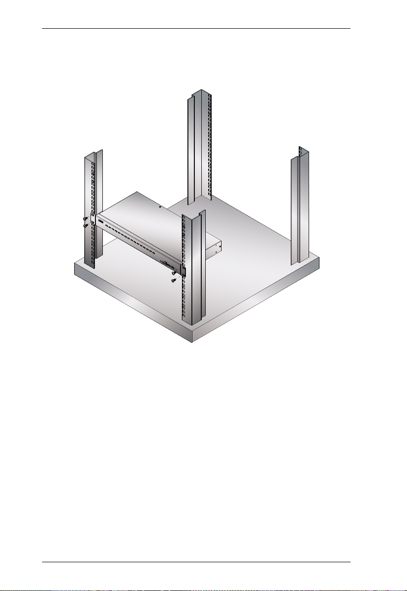
Rack Mounting – Front
1. Remove the screws, one each from the left and right sides near the front of
the unit.
2. Use the M3 x 6 Phillips hex head screws supplied with the rack mounting kit
to screw the rack mounting brackets into the sides near the front of the unit.
13
CS18208 / CS18216 User Manual
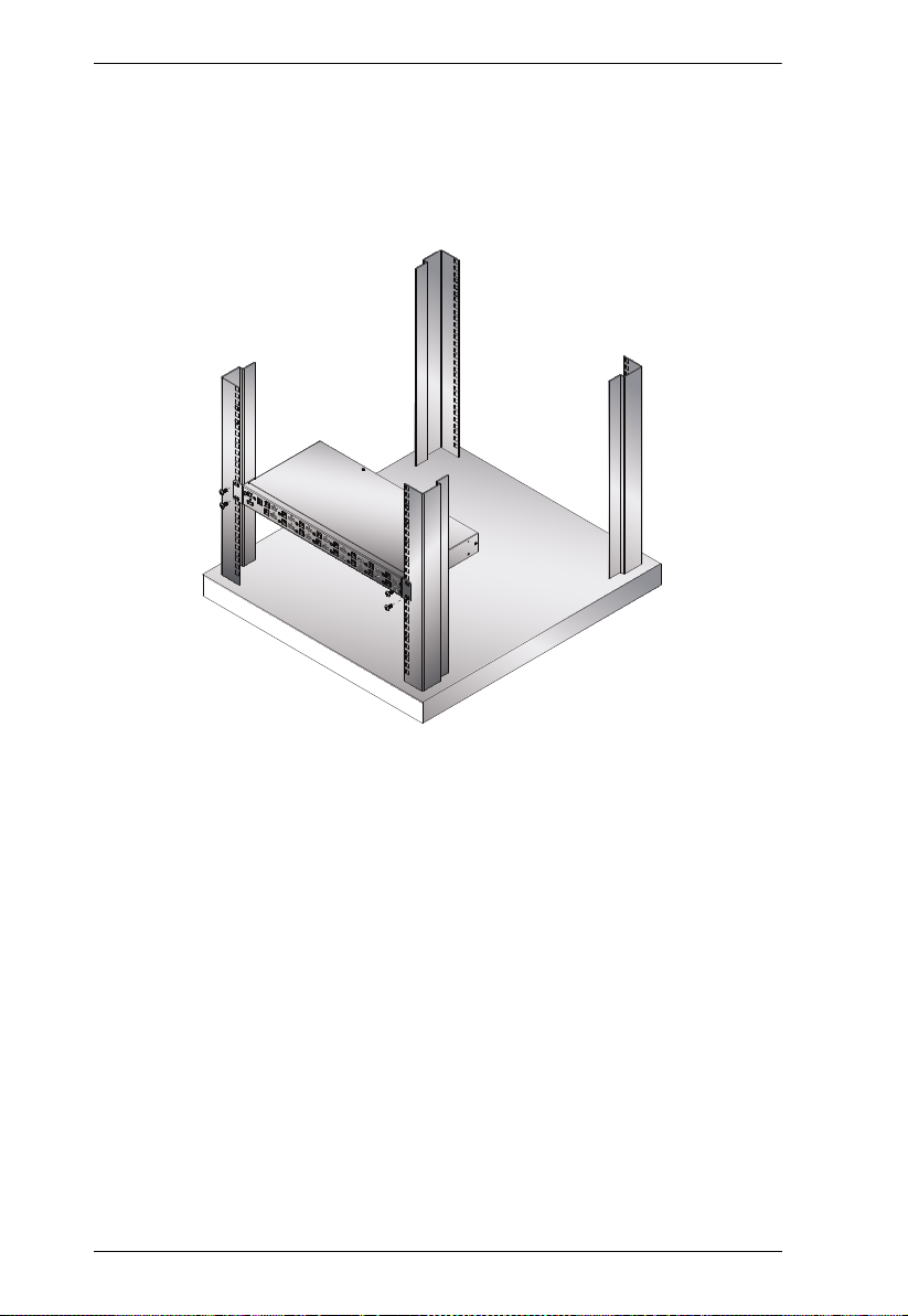
3. Place the KVM switch in the rack. Position it so that the holes in the
mounting brackets line up with the holes in the rack. Secure the mounting
brackets to the front of the rack.
14

2. Hardware Setup
3
Rack Mounting – Rear
1. Remove the screws, one each from the left and right sides of the switch
near the rear of the unit.
2. Use the M3 x 6 Phillips hex head screws supplied with the rack mounting kit
to screw the rack mounting brackets into the sides near the rear of the unit.
15
CS18208 / CS18216 User Manual
3. Place the KVM switch in the rack. Position it so that the holes in the
mounting brackets line up with the holes in the rack. Secure the mounting
brackets to the rear of the rack.
16

2. Hardware Setup
Single Stage Installation
To set up your single stage CS18208 / CS18216 installation, refer to the
installation diagram on page 18 (the numbers in the diagrams correspond to the
steps, below), and do the following:
1. Ground the CS18208 / CS18216 by connecting one end of a grounding
wire to the Grounding Terminal and the other end to a suitable grounded
object.
Note: Do not omit this step. Proper grounding helps to prevent damage to
the unit from power surges or static electricity.
2. Plug your USB keyboard and USB mouse into the USB console ports from
the Console Ports Section located on the unit’s rear panel.
3. Plug your HDMI monitor into the HDMI console port from the Console
Ports Section located on the unit’s rear panel and power on the monitor.
4. Plug your speakers into the Audio Jacks located on the unit’s front and rear
panel. The speakers plugged into the front panel have priority over those
plugged into the rear panel.
5. Use the provided cable sets (HDMI cable, USB 3.0 cable, and audio cable)
with this package. Plug the HDMI connector into any available HDMI port
in the KVM Ports Section of the switch (CPU 1, CPU 2, etc.), and then
plug the USB 3.0 cable and audio cable into their corresponding ports.
Note:
Verify that all the connectors are in the same KVM Ports Section (all
in CPU 1, all in CPU 2.).
The CS18208 / CS18216 only supports speaker ports. Do not connect a
KVM cable's microphone connector to the speaker ports.
6. At the other end of the cables from step 5, plug the HDMI cable, USB 3.0
cable, and audio cables into their respective ports on the computer. Repeat
steps 5, and 6 for other PC systems you are installing.
7. (Optional) Plug your USB peripherals into the USB Type-A ports in the
USB 3.1 Gen1 Peripheral Hub Section located on the unit’s front panel.
8. Plug the power adapter that came with your switch into an AC power
source, then plug power adapter cable into the switch’s Power Jack. Now
the CS18208 / CS18216 is turned on.
17

CS18208 / CS18216 User Manual
3
7
4
CS18216 (Front)
CS18216 (Rear)
812
5
6
IENJ!Dbcmf
4
9. Power on the computers.
Note: Make sure the computers and devices that the CS18208 / CS18216
connects to are also properly grounded.
Single Stage Installation Diagram
18

2. Hardware Setup
Two Stage Cascade
To control even more computers, additional CS18208 / CS18216 units can be
cascaded from the KVM ports of the First Stage unit. The cascaded CS18208 /
CS18216s that connect back to the First Stage unit are considered Second Stage
units. As many as 64 (CS18208) or 256 (CS18216) computers can be
controlled in a complete two stage installation. A table showing the relation
between the number of computers and the number of units needed to control
them is provided on page 93.
To set up a two stage installation, refer to the Two Stage Installation diagram
on the next page as you do the following:
1. Make sure that power to all the devices you will be connecting up,
including all preexisting devices on the installation, have been turned off.
2. Use the provided cable sets (HDMI cable, USB 3.0 cable, and audio cable)
with this package to connect any available KVM Port on the First Stage
unit to the Console ports of the Second Stage unit.
Note: Plug the USB Type-A connector into the lower USB (keyboard) port
in the Console section (they are both marked with a similar icon to
remind you of the correct USB port).
3. Using another provided cable sets (HDMI cable, USB 3.0 cable, and audio
cable) with this package, plug the HDMI connector into any available
HDMI port in the KVM Ports Section of the second stage switch, then
plug the accompanying USB Type-B, and audio cable into their
corresponding USB, and audio jack.
Note:
Verify that all the connectors are in the same KVM Ports Section (all in
CPU 1, all in CPU 2, etc.), and that each socket is marked with an
appropriate icon to indicate itself.
The CS18208 / CS18216 only supports speaker ports. Do not connect a
KVM cable's microphone connector to the speaker ports.
4. At the other end of the cables from step 3, plug the HDMI cable, USB 3.0
cable, and audio cables into their respective ports on the computer.
5. Repeat steps 3 and 4 for any other PC systems you are installing.
19

CS18208 / CS18216 User Manual
6. For each Second Stage unit, plug the power adapter cable into its Power
Jack, then plug the power adapter into an AC source.
7. Plug the First Stage unit's power adapter cable into its Power Jack, then
plug the power adapter into an AC source.
8. Power on the computers.
Note:
The Power On sequence requires that all Second Stage units be
powered on first. After they are all on, the First Stage units must be
powered on next. Only after all the switches have been powered on in
this sequence, can the computers be powered on.
The USB 3.1 hub cannot be accessed through the switch by computers
on the second level of a cascaded installation.
Make sure the computers and devices that the CS18208 / CS18216
connects to are also properly grounded.
20

Two Stage Installation Diagram
USB HDMI
KVM Cable Set
2. Hardware Setup
21

CS18208 / CS18216 User Manual
Three Stage Cascade
The procedures for setting up a three stage installation are essentially the same
as for a two stage installation. Using the CS18208 in a three stage setup, as
many as 512 computers can be controlled in a complete installation. A table
showing the relation between the number of computers and the number of
switches needed to control them is provided on page 73.
Note: 1. The CS18208 cannot cascaded beyond the third level and the
CS18216 cannot cascaded beyond the second level.
2. The CS18208 can only be cascaded with another CS18208 units. The
CS18216 can be cascaded with another CS18216 units.
Once you have finished cabling up (see Two Stage Cascade, page 19 if
necessary), power up according to the following sequence:
1. For each Third Stage unit, plug the power adapter cable into the switch's
Power Jack; plug the power adapter into an AC source.
2. For each Second Stage unit, plug the power adapter cable into the switch's
Power Jack; plug the power adapter into an AC source.
3. Plug the First Stage unit's power adapter cable into its Power Jack, then
plug the power adapter into an AC source.
4. Power on the computers.
Note: The Power On sequence requires that all Third Stage units be
powered on first. After they are all on, the Second Stage units
must be powered on next. After the Second Stage units are on, the
First Stage units must be powered on last. Only after all the
switches have been powered on in this sequence, can the
computers be powered on.
The USB 3.0 hub cannot be accessed through the switch by
computers on the second or third level of a cascaded installation.
Make sure the computers and devices that the CS18208 /
CS18216 connects to are also properly grounded.
22

Three Stage Installation Diagram
USB HDMI
KVM Cable Set
USB HDMI
KVM Cable Set
2. Hardware Setup
23

CS18208 / CS18216 User Manual
Multi-display Installation
The CS18208 / CS18216’s multi-display feature allows you to stack two, three,
four, or up to 8 units in a dual/triple/quad-display/multi-display installation to
control up to seven (CS18208) or fifteen (CS18216) computers at once. This
installation requires slightly different cabling than the standard cascade and
offers an extra level of switching flexibility for multiple-monitor installations
where each computer is fitted with multiple video cards.
Note: In a Multi-display installation, the CS18208 can only be connected to
CS18208 units, and the CS18216 can only be connected to CS18216
units.
Cable Connections for Multi-display Installation
To set up your multi-display installation, refer to the installation diagram on the
next page (the numbers in the diagrams correspond to the steps, below), and do
the following:
1. Use a standard USB Type-A to USB Type-B cable to connect the Port 8
USB Type-B port on the first stage unit to the USB Type-A port in the
Console section of the second switch.
Note:
Port 8 is reserved to connect the units in a multi-display installation, so
up to seven (CS18208) or fifteen (CS18216) computers can be
attached, using KVM ports 1–7 (CS18208) or ports 1–7/9–16
(CS18216).
Plug the USB Type-A connector into the lower USB (keybaord) Port in
the Console Port Section (both USB Ports are marked with a similar
icon to remind you of the correct USB port).
2. Use HDMI cables to connect the HDMI KVM port on the second
CS18208 / CS18216 unit to the second video-in port on the computers.
Note: Only HDMI video cables are necessary – the other ports in the KVM
section are not required in this installation.
3. Connect a display to the console section of the second switch.
4. Repeat steps 1–3 for any additional units, up to a total of 8 switches.
24

2. Hardware Setup
5
Computers with
2/3/4 video inputs
First Switch
5
HDMI cables
5
1
USB Type B to
Type A cable
Second Switch
3
Third / Fourth
Stage Units
4
2
5. Connect the cables for the first switch. See Single Stage Installation,
page 17 for full details. All video, audio and peripheral devices must be
connected to the first switch.
6. Power up the CS18208 / CS18216 units, starting with the first switch, and
then power on the computers.
Note: Make sure the computers and devices that the CS18208 / CS18216
connects to are also properly grounded.
Multi-display Installation Diagram
25

CS18208 / CS18216 User Manual
Ch1
Ch7 Ch6
First
Switch
Second
Switch
Third
Switch
Fourth
Switch
Grouping Ports into “Vertical” Channels
Once the cables have been connected and multi-display mode has been selected
in the OSD, the CS18208 / CS18216 auto-detects the channels and displaying
modes.Users can then assign them a channel number as the port name (the
channels are represented by the vertical columns in the diagram belo w). So, all
the Port 1s become Channel 1, all the Port 2s become Channel 2, ... , and all the
Port 7s become Channel 7. The ports will all be switched at the same time,
channel by channel.
Depending on the number of stages in your stack, a CS18208 / CS18216
installation offers dual display (two stages), triple display (three stages), quad
display (four stages) or multi-display (up to 8 stages) scenarios. For reference
purposes, the example shows a four-stage installation with quad display
functionality.
Note: Only one HDMI video signal can be displayed at a time, depending on
the configuration of the CS18208 / CS18216 unit on the first switch.
Channels Diagram
26

Chapter 3
Basic Operation
Hot Plugging
The CS18208 / CS18216 supports hot plugging – components can be removed
and added back into the installation by unplugging their cables from the ports
without the need to shut the unit down. In order for hot plugging to work
properly, the procedures described below must be followed:
Hot Plugging KVM Ports
In order for the OSD menus to correspond to KVM port changes, you must
manually reconfigure the OSD to reflect the new port information. See the F3
SET (page 37) and F4 ADM (page 39), functions for details.
Note: If the computer's operating system does not support hot plugging, this
function may not work properly.
Hot Plugging Console Ports
The keyboard, monitor, and mouse can all be hot plugged. When hot plugging
the mouse:
You may unplug and replug the mouse (to reset the mouse, for example),
as long as you use the same mouse.
If you plug in a different mouse, all the computers on the installation must
be shut down for 10 seconds, then restarted following the power up
sequence described under Steps 6, 7, and 8 under Two Stage Cascade,
page 19
Note: If, after hot plugging there is no response to keyboard and/or mouse
input, perform a Keyboard and Mouse Reset by simultaneously
pressing the 1 and 2 (CS18208 / CS18216) front panel pushbuttons.
27

CS18208 / CS18216 User Manual
Port Selection
The CS18208 / CS18216 provides four port selection methods to access the
computers on the installation: Manual, an OSD (on-screen display) menu
system, Hotkeys, and RS-232 commands.
For OSD (on-screen display), see Chapter 4 OSD Operation, page 31 for
more information.
For Hotkeys operation, see Chapter 5 Hotkey Operation, page 47 for more
information.
For RS-23 commands, see Chapter 7 RS-232 Operation, page 61 for more
information.
Manual Port Switching
Use the front panel pushbutton switches to manually switch to a port.
Port ID Numbering
Each port on a CS18208 / CS18216 installation is assigned a unique Port ID.
You can directly access any computer on any level of the installation by
specifying the Port ID that the computer is connected to – either with the OSD
(see OSD Operation, page 31), or with the Hotkey port selection method (see
Hotkey Operation, page 47).
A computer attached to a primary unit has a two digit Port ID (from 01–08
for the CS18208, or 01–16 for the CS18216) that corresponds to the KVM
port number that it is connected to.
A computer attached to a secondary unit has a four digit Port ID.
The first two digits represent the KVM port number on the primary unit
and the second two digits represent the KVM port number on the
secondary unit that the computer is connected to. For example, a Port ID
of 02–08 would refer to a computer that is connected to KVM port 8 of a
secondary unit that links back to KVM port 2 of the primary unit.
28

3. Basic Operation
Powering Off and Restarting
If it becomes necessary to power off a CS18208 / CS18216, do the following
before restarting it:
1. Unplug the CS18208 / CS18216 from its power source.
2. Shut down all the computers that are attached to it.
Note: Unplug the power cords of any computers that have the Keyboard
Power On function. Otherwise, the CS18208 / CS18216 will still
receive power from the computers.
3. Wait 10 seconds, then plug the CS18208 / CS18216 back in.
4. Power on the computers.
Note: If there are stations cascaded down from the primary CS18208 /
CS18216, all the cascaded stations and the computers attached to
them must be shut down as well.
29

CS18208 / CS18216 User Manual
This Page Intentionally Left Blank
30

Chapter 4
OSD Operation
OSD Overview
The on-screen display (OSD) is a mouse and keyboard enabled, menu driven
method to handle computer control and switching operations. All procedures
start from the OSD main screen.
Manufacturing Number
The “MFG Number” (Manufacturing Number) is an internal serial number
used by ATEN’s factory and technical support staff to identify products. This
number does not affect products’ warranty. If your product requires after-sales
services, you may provide the MFG Number to ATEN’s sales or technical
support staff to identify the product and model number.
OSD Login
The OSD incorporates a two level (administrator / user) password system.
Before the OSD main screen displays, a login screen appears requiring a
password. If this is the first time that the OSD is used, or if the password
function has not been set, please use default username and password:
administrator / password to log in. After you have logged in for the first time,
you will be asked to change the password for security purpose, please follow
the on-screen instructions to setup your new password. The OSD main screen
will display in administrator mode. In this mode, you have administrator
privileges, with full access to all functions, and can set up operations (including
password authorization) as you like.
31

CS18208 / CS18216 User Manual
OSD Hotkey
You can display the OSD on the console monitor while also viewing the
display of any port on the CS18208 / CS18216 by pressing the [Scroll Lock]
key twice.
Note: You can optionally change the OSD hotkey to the Ctrl key, in which
case you would press [Ctrl] twice (see OSD HOTKEY, page 37). With
this method, you must press the same [Ctrl] key.
OSD Main Screen
When you invoke the OSD, a screen similar to the one below appears:
Note:
The diagram depicts the administrator's main screen. The user main screen
does not show the F4 and F6 functions, since these are reserved for the
administrator and can't be accessed by users.
The OSD always starts in list view, with the highlight bar at the same
position it was in the last time it was closed.
Only the ports that have been set accessible by the administrator for the
current logged in user are visible (see SET ACCESSIBLE PORTS,
page 40).
Enable Mouse Emulation to operate the OSD using mouse. When the
Mouse Emulation is disabled, you can only operate the OSD using
keyboard.
a) To enable the Mouse Emulation via OSD, see Mouse Emulation,
page 42.
32

4. OSD Operation
b) To enable the Mouse Emulation via hotkeys, see Mouse Emulation
Control, page 55.
If the port list is collapsed, click on a switch number, or move the highlight
bar to it then press the Enter key to expand the list. Similarly, to collapse a
switch’s port list, click on the switch number, or move the highlight bar to
it then press the right Enter key to collapse the list.
OSD Main Screen Headings
PN This column lists the port ID numbers for all the KVM ports on the
QV If a port has selected for quick view scanning (see SET QUICK VIEW
PW The computers that are powered on and are online have a sun symbol
NAME If a port has been given a name (see EDIT PORT NAMES, page 41), its
installation. The simplest method to access a particular computer is
move the highlight bar to it, then press Enter.
PORTS, page 41), a check mark
in this column .
name appears in this column.
( √ )
displays in this column.
OSD Navigation
To dismiss the menu, and deactivate OSD, click at the upper right
corner of the OSD window; or press [Esc].
To log out, click
[F8].
To move up or down through the list one screen at a time, click the up and
down arrow symbols (
there are more list entries than what can appear on the main screen, the
screen will scroll.
To activate a port, click it, or move the highlight bar to it then press
[Enter].
After executing any action, you automatically go back to the menu one
level above.
at the left of the main screen, or press
), or use the [Pg Up] and [Pg Dn] keys. If
33

CS18208 / CS18216 User Manual
OSD Functions
OSD functions are used to configure and control the OSD. For example, you
can rapidly switch to any port, scan selected ports, limit the list you wish to
view, designate a port as a quick view port, create or edit a port name, or make
OSD setting adjustments.
To access an OSD function:
1. Either click on the function key field on the left of the main screen, or
press a function key on the keyboard.
2. In the submenus that appear make your choice either by clicking it, or
moving the highlight bar to it, then pressing [Enter].
3. Press [Esc] to return to the previous menu level.
34

F1: Go To
4. OSD Operation
Clicking
or pressing [F1] activates the Go To function. Go To
allows you to switch directly to a port by keying in the port's ID. Enable mouse
emulation for independent switching (see page 42), for this function to work.
To use the search method, key in the Port ID; then press [Enter] to switch
KVM, Audio and USB focus; or [Spacebar] to switch KVM and Audio
only.
35

CS18208 / CS18216 User Manual
F2: List
Clicking
or pressing [F2] activates the List function. This
function lets you broaden or narrow the scope of which ports the OSD displays
on the main screen. The submenu choices and their meanings are given in the
table below.
Choice Meaning
ALL Lists all of the ports on the installation that have been set accessible
Quick View Lists only the ports that have been selected as quick view ports (see
Powered On Lists only the ports that have their attached computers powered on.
Quick View +
Powered On
by the administrator for the current logged in user.
SET QUICK VIEW PORTS, page 41).
Lists only the ports that have been selected as quick view ports (see
SET QUICK VIEW PORTS, page 41), and that have their attached
computers powered on.
Move the highlight bar to the choice you want, then press [Enter]. A check
mark (
√
) appears before the choice to indicate that it is the currently selected
one.
36

F3: Set
4. OSD Operation
Clicking
or pressing [F3] activates the Set function. This function
allows the administrator and each user to set up his own working environment.
A separate profile for each is stored by the OSD and is activated according to
the username that was provided during login.
To change a setting:
1. Click it; or move the highlight bar to it, then press [Enter].
2. After you select an item, a submenu with further choices appears. To make
a selection, either click it; or move the highlight bar to it, then press
[Enter]. A check mark (
√
) appears before the selected choice to indicate
which one it is. The settings are explained in the following table:
Setting Function
OSD Hotkey Selects which hotkey activates the OSD function:
Port ID Display
Position
[Scroll Lock] [Scroll Lock] or [Ctrl] [Ctrl].
Since the [Ctrl] key combination may conflict with programs running
on the computers, the default is the [Scroll Lock] combination.
Allows each user to customize the position where the port ID
appears on the screen. The default is the upper left corner, but
users can choose to have it appear anywhere on the screen.
Use the mouse or the arrow keys plus Pg Up, Pg Dn, Home, and
End (on the numeric keypad with Num Lock off). Arrow keys move
the position one space at a time. Pg Up and Pg Dn brings position
to the top or bottom. Home and End brings the position to the
rightmost and leftmost of the screen.To position the port ID display,
then single-click or press [Enter] to lock the position and return to
the Set submenu.
37

CS18208 / CS18216 User Manual
Port ID Display
Duration
Determines how long a port ID displays on the monitor after a port
change has taken place. The choices are: 3 Seconds (default) and
Always Off.
Port ID Display
Mode
Selects how the port ID is displayed: the port number plus the port
name (Port Number + Port Name) (default); the port number
alone (Port Number); or the port name alone (Port Name).
Scan Duration Determines how long the focus dwells on each port as it cycles
through the selected ports in Auto Scan mode (see F7 SCAN,
page 45). Key in a value from 1–255 seconds, then press [Enter].
Default is 5 seconds; a setting of 0 disables the SCAN function.
Scan-Skip Mode Selects which computers will be accessed under skip mode
(see F5: SKP, page 43), and Auto Scan mode (see F7: SCAN,
page 45. Choices are:
ALL - All the ports which have been set accessible (see SET
ACCESSIBLE PORTS, page 40);
QUICK VIEW - Only those ports which have been set accessible
and have been selected as quick view ports (see SET QUICK
VIEW PORTS, page 41);
POWERED ON - Only those ports which have been set accessible
and are powered on;
QUICK VIEW + POWERED ON - Only those ports which have
been set accessible and have been selected as quick view ports
and are powered on. The default is ALL.
Note: The quick view choices only show up on the administrator's
screen, since only he has Quick View setting rights (see SET
QUICK VIEW PORTS, page 41).
Screen Blanker If there is no input from the console for the amount of time set with
this function, the screen is blanked. Key in a value from 1–30
minutes, then press [Enter]. The default setting of 0 disables this
function. The screen will be blanked in the amount of time set
(count from the moment when OSD is closed)
Hotkey
Command Mode
Enables / disables the hotkey command function in case a conflict
with programs running on the computers occurs.
Hotkey Sets the keyboard shortcut for invoking Hotkey Mode (see Hotkey
Setting Mode, page 48). Choices are: [NUM LOCK] + [-] (minus)
(default), and [CTRL] + [F12].
OSD Language Sets the language used in the OSD. Choices are: English (Default),
German, Japanese, Simplified Chinese, Traditional Chinese,
Spanish, French, and Russian.
38

F4: Admin
4. OSD Operation
Clicking
or pressing [F4] activates Admin function. F4 is an
administrator only function. It allows the administrator to configure and
control the overall operation of the OSD. To change a setting, click on the
settings item you want to configure, or use the up and down arrow ke ys to move
the highlight bar to it then press [Enter].
After you select an item, a submenu with further choices appears. Click an
item, or move the highlight bar to it then press [Enter]. A check mark (
√
)
appears before the selected item so that you know which one it is. The settings
are explained in the following table:
39

CS18208 / CS18216 User Manual
Setting Function
Set User Login This function is used to set usernames and passwords for the
Set Accessible
Ports
Set Logout
Timeout
administrator and users:
1. Usernames and passwords for one administrator and four users
can be set.
2. After you select the administrator field or one of the user fields,
a field that allows you to key in the username and password
appears. Usernames and passwords can be from 1 to 16
characters long and can consist of any combination of letters
and numbers (A–Z, 0–9) and some additional keys (* ( ) + : - , ?
. / space).
3. For each individual, key in the username and password, confirm
the password, choose SAVE, then press [Enter].
4. To modify or delete a previous username and/or password, use
the backspace key to erase individual letters or numbers. Press
[Enter] when done.
Note: Usernames and passwords are not case sensitive.
Usernames are displayed in capital letters in the OSD.
This function allows the administrator to define user access to the
computers on the installation on a port-by-port basis.
For each user, select the target port; then press the [Spacebar] to
cycle through the choices: F (full access), V (view only), or blank.
Repeat until all access rights have been set, then press [Enter].
The default is F for all users on all ports.
Note:
A blank setting means that no access rights are granted. The
port will not show up on the user's LIST on the main screen.
The administrator always has full access to all ports.
If there is no input from the console for the amount of time set with
this function, the user is automatically logged out. A login is
necessary before the console can be used again.
This enables other users to gain access to the computers when the
original user is no longer accessing them, but has forgotten to log
out. To set the timeout value, key in a number from 1–180 minutes,
then press [Enter]. The default setting of 0 disables this function.
Note: This feature does not function if Set Login Mode is disabled.
See Set Login Mode, page 42.
40

4. OSD Operation
Edit Port Names To help remember which computer is attached to a particular port,
Restore Default
Values
Clear The Name
List
Activate Beeper Choices are Y (on), or N (off). When activated, the beeper sounds
Set Quick View
Ports
every port can be given a name. This function allows the
administrator to create, modify, or delete port names.
To edit a port name:
1. Click the port, or use the navigation keys to move the highlight
bar to it.
2. Key in the new port name, or modify/delete the old one. The
maximum number of characters allowed for the port name is 12.
Legal characters include:
All alpha characters: A–Z
All numeric characters: 0–9
* ( ) + : - , ? . /
Case does not matter; the OSD displays the port name in all
capitals no matter how they were keyed in.
3. When you have finished editing, press [Enter] to have the
change take effect. To abort the change, press [Esc].
This function is used to undo all changes and return the setup to
the original factory default settings (See Factory Default Hotkeys
and Settings, page 97) except for the port name list, username and
password information, which are saved.
This function clears the port name list.
whenever a port is changed; when activating the Auto Scan
function (see F7 SCAN, page 45); or an invalid entry is made on an
OSD menu. The default is Y.
This function lets the administrator select which ports to include as
quick view ports.
To select/deselect a port as a quick view port, use the navigation
keys to move the highlight bar to it, then press [Spacebar].
When a port has been selected as a quick view port, A check
( √ )
mark
screen. When a port is deselected, the check mark
pears.
If one of the quick view options is chosen for the LIST view (see
F2 LIST, page 36), only a port that has been selected here
will display on the list.
If one of the quick view options is chosen for auto-scanning
(See Scan-Skip Mode, page 38), only a port that has been
selected here will be auto-scanned.
The default has no ports selected for quick view.
displays in the QV column of the LIST on the main
( √ )
disap-
41

CS18208 / CS18216 User Manual
Set Operating
System
This function allows the administrator to define the operating
system for the computer connected to each KVM port. The default
setting is Win (PC compatible).
To set the port operating system:
1. From the list, select the port for which you wish to set the com-
puter's operating system.
2. Set the operating system by pressing [Spacebar] to cycle
through Win, MAC, SUN, or Other.
3. Press [Esc] to exit. The operating system you selected is
assigned to the KVM port.
Firmware
Upgrade
In order to upgrade the CS18208 / CS18216 firmware (see
page 79), you must first enable Firmware Upgrade mode with this
setting.
When you bring up this menu, the current firmware version levels
are displayed. Select Y to enable Firmware Upgrade mode, or
select [Esc] to leave this menu without enabling it.
Keyboard
Language
Sets the language for the computer keyboard attached to the KVM
port. To select a keyboard language, single-click it, or use the
navigation keys to move the highlight bar to it, then press [Enter].
Choices are: Auto (default), (US) English, (UK) English, German
(Deutch), German (SWISS), French, Hungarian, Italian, Japanese,
Korean, Russian, Spanish, Swedish, Traditional Chinese, and
Simplified Chinese.
Mouse Emulation Enables / disable mouse emulation function.
Note: Supported in the first level of an installation only. Enable
mouse emulation to perform any independent switching of a port
and for Auto Scan Mode or Skip Mode to work.
Activate MultiDisplay
Enables multi-display mode for dual, triple, quad, or multi display
mode in multiple-monitor installations where each computer is
fitted with multiple video cards. See Multi-display Installation,
page 24, for full details.
Note: multi-display mode must be enabled on the OSD before the
cables are connected.
OSD Config Back
/ Restore
Enters OSD Configuration Backup / Restore mode. The Firmware
Management Utility lets you backup the current OSD configuration
of the CS18208 / CS18216, and restore it when necessary. Storing
the OSD configuration settings is useful when deploying more than
one installation that uses the same settings. See OSD
Configuration Backup/Restore, page 86, for full details.
Set Login Mode This function allows the administrator to request users to login or
not. When the login dialog box is disabled, the system disables the
login/logout function. If the system is re-started, the login/logout
function remains disabled.
42

F5: SKP
4. OSD Operation
Clicking
enables you to easily skip backward or forward – switching the console focus
from the currently active computer port to the previous or next accessible one.
Enable mouse emulation for Skip mode to work (see page 42).
The selection of computers available for skip mode switching is made with
the Scan–Skip mode setting under the F3: SET function (see page 37).
When you are in skip mode:
press [
←
] to skip to the previous accessible port on the list
press [
→ ]
↑
press [
port has cascaded a switch, then it skips to the last accessible port of that
switch
press [
cascaded a switch, then it skips to the first accessible port of that switch
Note: When you skip, you only skip to the previous or next accessible
If a port has been selected for Scan–Skip mode, when the focus switches to
that port, a set of [
ID displays.
While skip mode is in effect, the console will not function normally. You
must exit skip mode in order to regain control of the console.
To exit skip mode, press [Spacebar] or [Esc].
] to skip to the previous accessible port. If the previous accessible
↓
] to skip to the next accessible port. If the next accessible port has
computer that is in the Scan–Skip mode selection (see page 38).
or pressing [F5] invokes Skip (SKP) mode. This function
to skip to the next accessible port on the list
↑
], [ ↓ ], [ ← ], [
→ ]
symbol appears before its port
43

CS18208 / CS18216 User Manual
F6: BRC
F6 is an administrator only function. Clicking or pressing [F6],
invokes Broadcast (BRC) mode. When this function is in effect, commands
sent from the console are broadcast to all available computers on the
installation.
This function is particularly useful for operations that need to be performed on
multiple computers, such as performing a system wide shutdown, installing or
upgrading software, etc.
While BRC mode is in effect, a speaker symbol appears before the port ID
display of the port that currently has the console focus. When the port ID
with the speaker symbol displays.
While BRC mode is in effect, the mouse will not function normally. You
must exit BRC mode in order to regain control of the mouse.
To exit BRC mode, invoke the OSD (with the OSD hotkey), then click the
F6 field, or press [F6], to turn BRC mode off.
When BRC mode is in effect, the Scroll Lock LED flashes. It stops
flashing and reverts to normal status when you exit BRC.
44

F7: SCAN
4. OSD Operation
Clicking
or pressing [F7] invokes Auto Scan mode. This
function allows you to automatically switch among the available computers at
regular intervals so that you can monitor their activity without having to take
the trouble of switching yourself. Enable mouse emulation for Auto Scan to
work (see page 42).
The selection of computers to be included for auto-scanning is made with
the Scan–Skip mode setting under the F3: SET function (see page 38).
The amount of time that each port displays for is set with the Scan
Duration setting under the F3: SET function (see page 38). When you
want to stop at a particular location, press the [Spacebar] to stop scanning.
If the scanning stops on an empty port, or one where the computer is
attached but is powered Off, the monitor screen will be blank, and the
mouse and keyboard will have no effect. After the Scan Duration time is
up, the scan function will move on to the next port.
As each computer is accessed, an S appears in front of the port ID display
to indicate that it is being accessed under Auto Scan mode. When the port
ID with the symbol displays, the background screen is blank.
While Auto Scan mode is in effect, the console will not function normally.
You must exit Auto Scan mode in order to regain control of the console.
While you are in Auto Scan mode, you can pause the scanning in order to
keep the focus on a particular computer either by pressing P, or with a leftclick of the mouse. See Invoking Auto Scan, page 50, for details.
To ex it Auto Scan mode, press the [Spacebar] or [Esc].
45

CS18208 / CS18216 User Manual
F8: Logout
Clicking , or pressing [F8] logs you out of OSD control of the
computers, and blanks the console screen. This is different from simply
pressing [Esc] when you are at the main screen to deactivate the OSD. With
this function you must log in all over again to regain access to the OSD,
whereas with [Esc], all you have to do to reenter the OSD is tap the OSD
hotkey.
Note: 1. When you reenter the OSD after logging out, the screen stays blank
except for the OSD main screen. You must input your username and
password before you can continue.
2. If you reenter the OSD after logging out, and immediately use [Esc]
to deactivate the OSD without having selected a port from the OSD
menu, a NULL PORT message displays on the screen. The OSD
hotkey will bring up the main OSD screen.
46

Chapter 5
Hotkey Operation
Overview
Use hotkeys to operate and control the CS18208 / CS18216 KVM Switch from
a keyboard.
Providing KVM Focus via Hotkeys
You can use hotkeys to provide KVM focus to a particular computer by:
Selecting the active port
Enabling the auto scan mode
Enabling the skip mode
Resetting keyboard / mouse
Enabling / disabling mouse emulation
Supported Hotkeys
The CS18208 / CS18216 supports the following operation via hotkeys. For a
summary of the supported hotekys, see HSM Summary Table, page 57.
Enabling / disabling the beeper
Setting the hotkey for invoking the Hotkey Setting Mode
Setting the OSD hotkey between [Scroll Lock] [Scroll Lock] and [Ctrl]
[Ctrl]
Setting the port operating system for a specified port
Restoring the default value for the unit
Setting the EDID mode for the unit
Setting the switching mode selection for the unit
47

CS18208 / CS18216 User Manual
Hotkey Setting Mode
Hotkey Setting Mode is used to set up your CS18208 / CS18216 switch
configuration. All operations begin with invoking Hotkey Setting Mode
(HSM).
Invoking HSM
To invoke HSM do the following:
1. Press and hold down [Num Lock].
2. Press and release [-].
3. Release [Num Lock].
or
1. Hold down the [Ctrl] key;
2. Press and release the [F12] key;
3. Release the [Ctrl] key:
When HSM is active:
A command line appears on the monitor screen. The command line prompt
is the word HOTKEY: in white text on a blue background, and displays the
subsequent hotkey information that you key in.
Ordinary keyboard and mouse functions are suspended – only hotkey
compliant keystrokes (described in the sections that follow), can be input.
Pressing [Esc] exits HSM.
48

5. Hotkey Operation
Selecting the Active Port
Each KVM port is assigned a port ID (see Port ID Numbering, page 28). You
can directly access any computer on the installation with a hotkey combination
that specifies the port ID of the KVM port that a computer is connected to. To
access a computer using hotkeys:
1. Invoke HSM with the [Num Lock] + [-] or [Ctrl] + [F12] combination.
2. Key in the port ID.
The port ID numbers display on the command line as you key them in. If
you make a mistake, use [Backspace] to erase the wrong number.
3. Press [Enter].
After you press [Enter], the KVM focus switches to the designated
computer and you automatically exit HSM.
Note: In HSM, KVM focus will not switch to a port if an invalid switch or
port number is entered. The hotkey command line will continue to
display on the screen until you enter a valid switch and port number
combination, or exit HSM.
Hotkey Action
[PN] [Enter] Brings the KVM, USB hub, and audio focus to the
computer attached to the port corresponding to the
specified Port ID.
[PN] [K] [Enter] Brings only the KVM and audio focus to the computer
[PN] [U] [Enter] Brings only the USB hub focus to the computer
attached to the specified port. The USB hub focus
remain where they are.
attached to the specified port. The KVM and audio
focus remain where they are.
Note: The [PN] stands for the computer’s Port ID number (1, 2, 3, or 4). See
Port ID Numbering, page 28 for details. Replace the [PN] with the
appropriate Port ID when entering Hotkey combinations.
49

CS18208 / CS18216 User Manual
Auto Scan Mode
Auto Scan automatically switches, at regular intervals, among all the KVM
ports that have been set as accessible under Scan–Skip Mode, so that their
activity can be monitored automatically. See Scan–Skip Mode on page 38 for
more information.
Invoking Auto Scan:
To start Auto Scan, key in the following Hotkey combination:
1. Enable mouse emulation (see page 55).
2. Invoke HSM with the [Num Lock] + [-] or [Ctrl] + [F12] combination.
3. Press [A]. After you press A, then [Enter], you automatically exit HSM,
and enter Auto Scan mode.
While you are in Auto Scan mode, you can pause the scanning in order
to keep the focus on a particular computer either by pressing P or with
a left click of the mouse. During the time that auto-scanning is paused,
the command line displays: AUTO SCAN: PAUSED.
Pausing when you want to keep the focus on a particular computer is
more convenient than exiting Auto Scan mode because when you
resume scanning, you start from where you left off. If, on the other
hand, you exited and restarted, scanning would start over from the very
first computer on the installation.
To resume Auto Scanning, press any key or left-click. Scanning
continues from where it left off.
While Auto Scan mode is in effect, ordinary keyboard and mouse
functions are suspended – only Auto Scan mode compliant keystrokes
and mouse clicks can be input. You must exit Auto Scan mode in order
to regain normal control of the console.
4. To exit Auto Scan mode press [Esc] or [Spacebar]. Auto-scanning stops
when you exit Auto Scan mode.
Note: Enable mouse emulation to perform any independent switching of a
port and for Auto Scan Mode or Skip Mode to work (see page 55)
50

5. Hotkey Operation
Skip Mode
This feature allows you to switch between computers in order to monitor them
manually. You can dwell on a particular port for as long as you like – as
opposed to auto-scanning, which automatically switches after a fixed interval.
To invoke Skip mode, key in the following hotkey combination:
1. Enable mouse emulation (see page 55).
2. Invoke HSM with the [Num Lock] + [-] or [Ctrl] + [F12] combination.
3. Key in [
↑
], [ ↓ ], [ ← ], or [
→ ].
After you press an arrow key, you automatically exit HSM and enter
Skip mode where you can switch ports as follows:
← Skips to the previous accessible port. (See Scan/Skip Mode,
page 38, for information regarding accessible ports.)
→ Skips to the next accessible port.
Skips to the previous accessible port. If the previous accessible
↑
port has cascaded a switch, then it skips to the last accessible
port of that switch.
Skips to the next accessible port. If the next accessible port has
↓
cascaded a switch, then it skips to the first accessible port of that
switch.
Once you are in Skip mode, you can keep on skipping by pressing the
arrow keys. You don't have to use the [Num Lock] + [-] combination
again.
While Skip mode is in effect, ordinary keyboard and mouse functions
are suspended – only Skip mode compliant keystrokes can be input.
You must exit Skip mode in order to regain normal control of the
console.
4. To exit Skip mode, press [Esc] or [Spacebar].
Note: Enable mouse emulation to perform any independent switching of a port
and for Auto Scan Mode or Skip Mode to work (see page 55).
51

CS18208 / CS18216 User Manual
Keyboard / Mouse Reset
If the keyboard or mouse cease to function on the computer connected to the
currently selected port, you can perform a keyboard / mouse reset on the
computer. This function is essentially the same as unplugging and replugging
the keyboard and mouse on the target computer. To perform a computer
keyboard / mouse reset, key in the following hotkey combination:
1. Invoke HSM with the [Num Lock] + [-] or [Ctrl] + [F12] combination.
2. Press [F5].
After you press [F5] you automatically exit HSM and regain keyboard and
mouse control on the computer connected to the KVM port. If you fail to regain
keyboard / mouse control on the computer after pressing [F5], perform a
console keyboard and mouse reset.
Hotkey Beeper Control
The beeper (see Activate Beeper, page 41) can be hotkey toggled on and off.
The default setting is enabled. To toggle the beeper, key in the following
hotkey combination:
1. Invoke HSM with the [Num Lock] + [-] or [Ctrl] + [F12] combination.
2. Press [B].
After you press [B], the beeper toggles on or off. The command line displays
BEEPER ON or BEEPER OFF for one second; then the message disappears
and you automatically exit HSM.
HSM Hotkey Control
The HSM Hotkey (see Hotkey, page 38) can be toggled between
[Num Lock] + [-], and [Ctrl] + [F12]. To toggle the HSM Hotkey:
1. Invoke HSM with the [Num Lock] + [-] or [Ctrl] + [F12] combination.
2. Press [H].
After you press [H], the command line displays HOTKEY HAS BEEN
CHANGED for one second; then the message disappears and you
automatically exit HSM.
52

5. Hotkey Operation
OSD Hotkey Control
The OSD Hotkey (see OSD Hotkey, page 37) can be toggled between [Scroll
Lock], [Scroll Lock] and [Ctrl], [Ctrl]. To toggle the OSD Hotkey, key in the
following hotkey combination:
1. Invoke HSM with the [Num Lock] + [-] or [Ctrl] + [F12] combination.
2. Press [T].
After you press [T], the command line displays HOTKEY HAS BEEN
CHANGED for one second; then the message disappears and you
automatically exit HSM.
Port OS Control
A port’s operating system can be changed to match that of the computer
attached to the port. To change a port’s operating system, key in the following
hotkey combination:
1. Invoke HSM with the [Num Lock] + [-] or [Ctrl] + [F12] combination.
2. Key in [F1], [F2], or [F3], the Function of [F1], [F2], and [F3] keys is
listed in the following table:
Key Description
F1 Sets the Port OS to Windows
F2 Sets the Port OS to Mac
F3 Sets the Port OS to Sun
After pressing a function key you automatically exit HSM.
53

CS18208 / CS18216 User Manual
Restore Default Values
This administrator-only hotkey restores the CS18208 / CS18216 default
values. see Factory Default Hotkeys and Settings, page 97. To restore the
default values, key in the following hotkey combination:
1. Invoke HSM with the [Num Lock] + [-] or [Ctrl] + [F12] combination.
2. Press [R].
3. Press [Enter].
After you press [Enter], the command line displays RESET TO DEFAULT
SETTING for one second; then the message disappears and you
automatically exit HSM.
Video DynaSync
Video DynaSync is ATEN’s exclusive technology that eliminates boot-up
display problems and optimizes resolution when switching between ports. The
default setting is enabled. To invoke Video DynaSync, do the following:
1. Invoke HSM with the [Num Lock] + [-] or [Ctrl] + [F12] combination.
2. Press [D].
Note: If the monitor is disconnected and reconnected, the CS18208 /
CS18216 re-executes Video DynaSync.
54

5. Hotkey Operation
EDID Mode
To configure an EDID mode for the CS18208 / CS18216, do the following:
1. Invoke HSM with the [Num Lock] + [-] or [Ctrl] + [F12] combination.
2. Press [V].
3. Key in [1], or [2], the Function of [1], and [2] keys is listed in the
following table:
Key Description
1 Sets the switch to read HDMI
monitor’s EDID (Default)
2 Sets the switch to ATEN default
EDID mode
4. Press [Enter]. After pressing [Enter] you automatically exit HSM.
Mouse Emulation Control
The default setting is enabled. To disable, do the following:
1. Invoke HSM with the [Num Lock] + [-] or [Ctrl] + [F12] combination.
2. Press [M].
This procedure is a toggle. Repeat to enable.
Note: Enable mouse emulation to perform any independent switching of a port
and for Auto Scan Mode or Skip Mode to work.
55

CS18208 / CS18216 User Manual
Switching Mode Selection
This administrator-only hotkey allows you to select an appropriate switching
mode between Normal Switching Mode and Fast Switching Mode.
Note: This hotkey is only supported by CS18208 / CS18216 using firmware
version v1.1.102 or later.
To change the switching mode, key in the following hotkey combination:
1. Invoke HSM with the [Num Lock] + [-] or [Ctrl] + [F12] combination.
2. Press [P].
3. Key in [1] or [2], the Function of [1] and [2] keys is listed in the following
table:
Key Description
1 Sets the KVM to Normal
Switching Mode (Default)
2 Sets the KVM to Fast Switching
Mode
4. Press [Enter]. The command line indicates the current switching mode for
one second and the system automatically exits HSM.
Note: The configuration of Fast Switching Mode might not work with some
monitors. If your video output does not display successfully or work
properly, please use the default Normal Switching Mode instead.
56

5. Hotkey Operation
HSM Summary Table
After invoking HSM (see page 48), key in one of the following keys to perform
the corresponding function:
Key Function
[PN] [Enter] Switches KVM, Audio, and USB focus directly to the
[PN] [K] [Enter] Switches KVM and Audio focus directly to the computer
[PN] [U] [Enter] Switches USB focus only directly to the computer that
[A] [Enter] Starts Auto Scan. The KVM focus cycles from port to port
[A] [n] [Enter] Starts Auto Scan at n-second intervals (n = 0–255
[H] Toggles between the default ([Num Lock] [-]) and alternate
[T] Toggles between the default ([Scroll Lock] [Scroll Lock])
[F1] Sets the port OS to Windows.
[F2] Sets the port OS to Mac.
[F3] Sets the port OS to Sun.
computer that corresponds to that port ID. (PN = port
number)
that corresponds to that port ID. (PN = port number)
corresponds to that port ID. (PN = port number)
Note: This hotkey functions on the first level of an
installation only.
at the default 5-second intervals
seconds)
Note: When n=0, the Auto Scan will not be activated.
([Ctrl] [F12]) HSM invocation keys.
and alternate ([Ctrl] [Ctrl]) OSD Hotkey.
[F5] Performs a keyboard / mouse reset on the target
computer.
[B] Enables/Disables the beeper.
[R] [Enter] Resets the hotkey settings to their default status. See
Factory Default Hotkeys and Settings, page 97.
[D] Invokes Video DynaSync, ATEN’s exclusive technology
that eliminates boot-up display problems and optimizes
resolution when switching between ports.
57

CS18208 / CS18216 User Manual
Key Function
[V] [n] [Enter] Sets EDID Mode.
n = 1, read HDMI monitor’s EDID.
n = 2, ATEN default EDID mode (Full HD 1920 x 1080
@60Hz).
[P] [n] [Enter] Sets the KVM switching mode.
n = 1, sets the KVM to Normal Switching Mode.
n = 2, sets the KVM to Fast Switching Mode.
Note: This hotkey is only supported by CS18208 /
CS18216 using firmware version v1.1.102 or later.
[M] Enables/Disables mouse emulation.
[ ← ] Skips to the previous computer on the list, in skip mode.
[ → ] Skips to the next computer on the list, in skip mode.
[ ↑ ] Skips to the previous accessible port. If the previous
accessible port has cascaded a switch, then it skips to the
last accessible port of that switch.
[ ↓ ] Skips to the next accessible port. If the next accessible
[ESC] or
[Spacebar]
port has cascaded a switch, then it skips to the first
accessible port of that switch.
Exits hotkey setting mode.
Note: Enable mouse emulation to perform any independent switching of a port
and for Auto Scan Mode or Skip Mode to work (see page 55).
58

Chapter 6
Keyboard Emulation
Mac Keyboard
The PC compatible (101/104 key) keyboard can emulate the functions of the
Mac keyboard. The emulation mappings are listed in the table below.
PC Keyboard Mac Keyboard
[Shift] Shift
[Ctrl] Ctrl
[Ctrl] [1]
[Ctrl] [2]
[Ctrl] [3]
[Ctrl] [4]
[Alt] Alt
[Print Screen] F13
[Scroll Lock] F14
=
[Enter] Return
[Backspace] Delete
[Insert] Help
[Ctrl]
F15
Note: When using key combinations, press and release the first key (Ctrl),
then press and release the activation key.
59

CS18208 / CS18216 User Manual
+
Sun Keyboard
The PC compatible (101/104 key) keyboard can emulate the functions of the
Sun keyboard when the Control key [Ctrl] is used in conjunction with other
keys. The corresponding functions are shown in the table below.
PC Keyboard Sun Keyboard
[Ctrl] [T] Stop
[Ctrl] [F2] Again
[Ctrl] [F3] Props
[Ctrl] [F4] Undo
[Ctrl] [F5] Front
[Ctrl] [F6] Copy
[Ctrl] [F7] Open
[Ctrl] [F8] Paste
[Ctrl] [F9] Find
[Ctrl] [F10] Cut
[Ctrl] [1]
[Ctrl] [2]
[Ctrl] [3]
[Ctrl] [4]
[Ctrl] [H] Help
-
Compose
Note: When using key combinations, press and release the first key (Ctrl),
then press and release the activation key.
60

Chapter 7
Firmware Upgrade Cable
RS-232 Operation
Overview
The CS18208 / CS18216’s built-in bi-directional RS-232 serial interface
allows system control through a high-end controller or PC. RS-232 serial
operations in a CS18208 / CS18216 installation are managed via
HyperTerminal sessions on systems that are running Windows. In order to use
this feature to send commands to the CS18208 / CS18216, you must first
download and install a HyperTerminal application.
Setup
Install a HyperTerminal application on a computer that is not part of the
installation, which will be used to control the switch via the RS-232
connection. HyperTerminal applications can be download from the Internet,
and many operating systems are embedded with HyperTerminal applications.
Hardware Connection
Use a the Firmware Upgrade Cable provided with this unit to connect a
computer’s serial port to the Firmware Upgrade Port on the CS18208 /
CS18216’s front panel, as shown below:
Note: The unit used in the diagram below is CS18216, the procedure for
connecting CS18208 is identical with fewer KVM ports.
61

CS18208 / CS18216 User Manual
14
RS-232 Pin Assignments
Pin assignments for the CS18208 / CS18216’s Firmware Upgrade Port that is
used for connecting to a serial terminal are given in the table, below:
Pin Assignment
1 TXD: Transmit Data
2 RXD: Receive Data
3N/A
4 GND: Signal Ground
RJ-11 Female
62

Chapter 7. RS-232 Operation
Console Login - HyperTerminal
Once a physical connection from the computer to the CS18208 / CS18216 has
been made, you can establish a HyperTerminal session using the instructions
below.
1. Open the HyperTerminal application, and configure the port settings for
COM1 port, then click OK.
Bits per Second: 19200, Data Bits: 8, Parity: None, Stop bits: 1, Flow Control:
None.
2. After configuring the port settings you must enable serial control on the
switch by typing the command: Open + [Enter].
63

CS18208 / CS18216 User Manual
RS-232 Commands
After you login via HyperTerminal (see Console Login - HyperTerminal) use
the instructions below to send RS-232 commands to control the switch from the
computer.
When RS-232 control is enabled via the Open + [Enter] command, the
CS18208 / CS18216’s front panel pushbuttons, OSD, hotkeys, and remote
control commands will be disabled - until the RS-232 control is disabled.
Verification
After entering a command, a verification message appears, as shown below, at
the end of the command line, as follows:
Response Message Description
Command OK Command or parameter is correct.
Command incorrect Command or parameter is incorrect.
With all commands in the sections that follow:
Each command string can be separated with a space.
The [Enter] command can be replaced with the ASCII code: 0x0D0A
64

Chapter 7. RS-232 Operation
Login
The Login command allows you to login to the CS18208 / CS18216 and begin
sending RS-232 commands. When you login the RS-232 link is “opened”, and
the CS18208 / CS18216 will not respond to front panel pushbuttons, hotkeys,
OSD, or remote control commands - until the RS-232 link is closed (see Switch
Port, page 69).
Use the Formula - to set Parameters - to create a Command.
Formulas:
Command + Control + Name + Number + [Enter]
Parameters:
Command Description
login Login command
Control Description
U Input user name + password
Name Description
xxxxxxxxxxxxx The login user name
Password Description
xxxxxxxxxxxxx The login user password
Enter Description
Enter Enter and send out command
Login Command
The available formula for the Login command is as follows:
1. Command + Control + Name + Number + [Enter]
For example, to login via username and password, type the following:
login u administrator p12345 [Enter]
65

CS18208 / CS18216 User Manual
Logout
The Logout commands allows you to logout of the CS18208 / CS18216 and
close the RS-232 link.
Use the Formula - to set Parameters - to create a Command.
Formulas:
Command + [Enter]
Parameters:
Command Description
logout Logout command
Enter Description
Enter Enter and send out command
Logout Command
The available formula for the Logout command is as follows:
1. Command + [Enter]
For example, to logout of the CS18208 / CS18216, type the following:
logout [Enter]
66

Chapter 7. RS-232 Operation
Open / Close RS-232 Link
The Open and Close RS-232 Link commands allows you to open/close the link
between the computer sending RS-232 commands and the CS18208 /
CS18216. When the link is open, the CS18208 / CS18216 only accepts RS-232
commands and will not respond to front panel pushbuttons, OSD, hotkeys, and
remote control commands - until the link is closed. The link opens when you
login and closes after 2 minutes if no command is sent.
Use the Formula - to set Parameters - to create a Command.
Formulas:
Command + [Enter]
Parameters:
Command Description
open Open RS-232 Link command
close Close RS-232 Link command
Enter Description
Enter Enter and send out command
Open/Close RS-232 Link Commands
The available formulas for the Open/Close RS-232 Link commands are as
follows:
1. Command + [Enter]
For example, to open the RS-232 link between the computer and CS18208 /
CS18216, type the following:
open [Enter]
2. Command + [Enter]
For example, to close the RS-232 link between the computer and CS18208 /
CS18216, type the following:
close [Enter]
67

CS18208 / CS18216 User Manual
Set Baud Rate
The Set Baud Rate command allows you to configure the baud rate setting for
the serial port connection. The default baud rate is 19200.
Use the Formula - to set Parameters - to create a Command.
Formulas:
Command + Control + [Enter]
Parameters:
Command Description
baud Baud Rate Command
Control Description
19200 Set baud rate to 19200 (Default)
38400 Set baud rate to 38400
9600 Set baud rate to 9600
Enter Description
Enter Enter and send out command
Set Baud Rate Commands
The available formulas for the Set Baud Rate commands are as follows:
1. Command + Control + [Enter]
For example, to set the baud rate to 19200, type the following:
baud 19200 [Enter]
2. Command + Control + [Enter]
For example, to set the baud rate to 38400, type the following:
baud 38400 [Enter]
68

Chapter 7. RS-232 Operation
Switch Port
The Switch Port command allows you to switch ports. The default port is 01.
Use the Formula - to set Parameters - to create a Command.
Formula:
Command + Control + [Enter]
Parameters:
Command Description
sw Switch Port Command
Control Description
ixx Input Port Number
xx= 01~08 (CS18208); 01~16 (CS18216)
Enter Description
Enter Enter and send out command
Switch Port Commands
The available formula for the Switch Port command is as follows:
1. Command + Control + [Enter]
For example, to switch to port 2, type the following:
sw i02 [Enter]
Note: The Control command can be skipped and the default value will be
used.
69

CS18208 / CS18216 User Manual
Hotkey Setting
The Hotkey Setting command allows you to change the hotkey used to invoke
the HSM (Hotkey Setting Mode). The default hotkey is [Num Lock] + [-].
Use the Formula - to set Parameters - to create a Command.
Formulas:
Command + Control + [Enter]
Parameters:
Command Description
hotkey Hotkey Setting Command
Control Description
num Change the HSM invoke key to:
[Num Lock] + [-] (Default)
f12 Change the HSM invoke key to:
[Ctrl] + [F12]
Enter Description
Enter Enter and send out command
Hotkey Setting Commands
The available formulas for Hotkey Setting commands are as follows:
1. Command + Control + [Enter]
For example, to change the HSM invoke key to [Num Lock] + [-], type the
following:
hotkey num [Enter]
2. Command + Control + [Enter]
For example, to change the HSM invoke key to [Ctrl] + [F12], type the
following:
hotkey f12 [Enter]
70

Chapter 7. RS-232 Operation
OSD Hotkey
The OSD Hotkey command allows you to change the hotkey used to invoke the
OSD. The default hotkey is [Scroll][Scroll].
Use the Formula - to set Parameters - to create a Command.
Formulas:
Command + Control + [Enter]
Parameters:
Command Description
osdkey OSD Hotkey Command
Control Description
scroll Change OSD hotkey invoke key to:
[Scroll] [Scroll] (Default)
ctrl Change OSD hotkey invoke key to:
[Ctrl] [Ctrl]
Enter Description
Enter Enter and send out command
Hotkey Switching Commands
The available formulas for OSD Hotkey commands are as follows:
1. Command + Control + [Enter]
For example, to change the OSD hotkey invoke key to [Scroll] [Scroll], type
the following:
osdkey scroll [Enter]
2. Command + Control + [Enter]
For example, to change the OSD hotkey invoke key to [Ctrl] [Ctrl], type the
following:
osdkey ctrl [Enter]
71

CS18208 / CS18216 User Manual
USB Reset
The USB Reset command allows you to reset the USB connection. The default
USB reset setting is off.
Use the Formula - to set Parameters - to create a Command.
Formulas:
Command + Control + [Enter]
Parameters:
Command Description
usbreset USB Reset Command
Control Description
on Enable USB reset connection
Enter Description
Enter Enter and send out command
USB Reset Command
The available formula for the USB Reset command is as follows:
1. Command + Control + [Enter]
For example, to reset the USB connection, type the following:
usbreset on [Enter]
72

Chapter 7. RS-232 Operation
Restore Default Settings
The Restore Default Settings command allows you to reset all of the CS18208
/ CS18216’s settings back to the default. The default setting is off.
Use the Formula - to set Parameters - to create a Command.
Formulas:
Command + Control + [Enter]
Parameters:
Command Description
reset Restore Default Settings Command
Control Description
on Enable restore default values
Enter Description
Enter Enter and send out command
Restore Default Value Command
The available formula for the Restore Default Settings command is as follows:
1. Command + Control + [Enter]
For example, to restore all CS18208 / CS18216’s settings back to the default,
type the following:
reset on [Enter]
73

CS18208 / CS18216 User Manual
Firmware Upgrade
The Firmware Upgrade command allows you to enable the firmware upgrade
mode. The default setting is off.
Use the Formula - to set Parameters - to create a Command.
Formulas:
Command + Control+ [Enter]
Parameters:
Command Description
upgrade Firmware Upgrade Command
Control Description
on Enable firmware upgrade mode
Enter Description
Enter Enter and send out command
Firmware Upgrade Command
The available formula for the Firmware Upgrade command is as follows:
1. Command + Control + [Enter]
For example, to enable firmware upgrade mode, type the following:
upgrade on [Enter]
74

Chapter 7. RS-232 Operation
KVM Status
The KVM Status command allows you to display read-only information about
the CS18208 / CS18216’ current configuration status. The default setting is off.
Use the Formula - to set Parameters - to create a Command.
Formulas:
Command + Control + [Enter]
Parameters:
Command Description
status KVM Status Command
Control Description
on Enable KVM status
Enter Description
Enter Enter and send out command
KVM Status Command
The available formula for the KVM Status command is as follows:
1. Command + Control + [Enter]
For example, to display the CS18208 / CS18216’s configuration status, type
the following:
status on [Enter]
A message similar to the one below will then appear:
hotkey: [numlock]+[-] / [scrolllock],[scrolllock]
os setting: pc
keyboard emulation: enabled/disabled
keyboard layout: English
mouse emulation: enabled/disabled
monitor re-detection: enabled/disabled
75

CS18208 / CS18216 User Manual
EDID Mode
The EDID Mode command allows you to set EDID mode for the CS18208 /
CS18216.
Use the Formula - to set Parameters - to create a Command.
Formulas:
Command + Control + [Enter]
Parameters:
Command Description
edid Set EDID Mode Command
Control Description
port1 Set to display (HDMI monitor) EDID
default Set to ATEN default EDID
Enter Description
Enter Enter and send out command
EDID Mode Command
The available formula for the KVM Status command is as follows:
1. Command + Control + [Enter]
For example, to set the CS18208 / CS18216’s EDID mode to ATEN default
EDID, type the following:
edid default [Enter]
76

Chapter 7. RS-232 Operation
Broadcast Mode
The Broadcast Mode command allows you to set enable/disable broadcast
mode for the CS18208 / CS18216. The default setting is off.
Use the Formula - to set Parameters - to create a Command.
Formulas:
Command + Control + [Enter]
Parameters:
Command Description
broadcast Set Broadcast Mode Command
Control Description
on Enable broadcast mode for CS18208 /
off Disable broadcast mode for CS18208 /
Enter Description
Enter Enter and send out command
CS18216
CS18216
Broadcast Mode Command
The available formula for the KVM Status command is as follows:
1. Command + Control + [Enter]
For example, to enable the CS18208 / CS18216’s broadcast mode, type the
following:
broadcast on [Enter]
77

CS18208 / CS18216 User Manual
This Page Intentionally Left Blank
78

Chapter 8
The Firmware Management Utility
Introduction
The purpose of the Windows-based Firmware Management Utility is to
provide an automated process for upgrading all CS18208 / CS18216 switches
in an installation. The program comes as part of a Firmware Upgrade Package
that is specific for each device.
As new firmware versions become available, new firmware upgrade packages
are posted on our website. Check the website regularly to find the latest
information and packages.
Downloading the Firmware Upgrade Package
To download the firmware upgrade package:
1. From a computer that is not part of your KVM installation go to our
website and choose the model name that relates to your device. A list of
available firmware upgrade packages appears.
2. Choose the firmware upgrade package that you wish to install (usually the
most recent) and download it to your computer.
79

CS18208 / CS18216 User Manual
Firmware Upgrade Cable
Preparation
To prepare for the firmware upgrade, do the following:
1. Use the Firmware Upgrade Cable provided with this unit to connect a COM
port on your computer to the Firmware Upgrade Port of your switch.
2. Shut down all the computers on the KVM installation.
3. From your KVM switch console, login to the OSD as the administrator
(see p. 31) and select the F4 Admin function.
4. Scroll down to Firmware Upgrades. Press [Enter], then press [Y] to
invoke Firmware Upgrade mode (see p. 42).
Or
Invoke the Firmware Upgrade mode using RS-232 command (see p. 74).
80

8. The Firmware Management Utility
Starting the Upgrade
To upgrade the firmware:
1. Run the downloaded firmware upgrade package file either by double-
clicking the file icon, or by opening a command line and entering the full
path to it.
The Firmware Upgrade Utility welcome screen appears:
Note: The screens shown in this section are for reference only. The
wording and layout of the actual screens put up by the Firmware
Upgrade Utility may vary slightly from these examples.
2. Read and Agree to the License Agreement (enable the I Agree radio button).
81

CS18208 / CS18216 User Manual
CS18208/CS18216 [MAIN]..
3. Click Next to continue. The Firmware Upgrade Utility main screen
appears. The devices capable of being upgraded are listed in the Device
List panel:
CS18208/CS18216 [MAIN]..
4. As you select a device in the list, its description appears in the Device
Description panel.
5. Click Next to perform the upgrade.
If you enabled Check Firmware Version, the Utility compares the device's
firmware level with that of the upgrade files. If it finds that the device's
version is higher than the upgrade version, it brings up a dialog box
82

8. The Firmware Management Utility
The firmware [Ver 1.0.] is not newer than the current firmware
[Ver 1.0.090] in device CS18208/CS18216 [MAIN]: 000
Continue the upgrade? [Yes/No]
informing you of the situation and gives you the option to continue or
cancel.
If you didn't enable Check Firmware Version, the Utility installs the
upgrade files without checking whether they are a higher level, or not.
As the upgrade proceeds, status messages appear in the Status Messages
panel, and the progress toward completion is shown on the Progress bar.
83

CS18208 / CS18216 User Manual
CS18208/CS18216 [MAIN]..
CS18208/CS18216 [MAIN]
CS18208/CS18216 [MAIN]000:OK
CS18208/CS18216 [MAIN] :000
Upgrade Succeeded
After the upgrade has completed, a screen appears to inform you that the
procedure was successful.
Click Finish to close the Firmware Upgrade Utility.
After a successful completion, the switches exit Firmware Upgrade Mode, and
reset themselves.
Upgrade Failed
If the Upgrade Succeeded screen doesn't appear, it means that the upgrade
failed to complete successfully. See the next section, Firmware Upgrade
Recovery, for how to proceed.
84

8. The Firmware Management Utility
Firmware Upgrade Recovery
There are three conditions that call for firmware upgrade recovery:
When a firmware upgrade is manually aborted.
When the mainboard firmware upgrade fails.
When the I/O firmware upgrade fails.
To perform a firmware upgrade recovery, do the following:
1. Power off the switch.
2. Connect the Firmware Upgrade Cable to its Firmware Upgrade Port.
3. Slide the Firmware Upgrade Recovery Switch to the Recover position.
4. Power the switch back on and repeat the upgrade procedure.
5. After the switch has been successfully upgraded, power it off, and slide the
Firmware Upgrade Recovery Switch back to the Normal position.
6. If the switch is one of the cascaded switches, plug it back into the
installation.
7. Power the switch back on.
85

CS18208 / CS18216 User Manual
OSD Configuration Backup/Restore
The Firmware Management Utility lets you backup the current OSD
configuration of the CS18208 / CS18216, and restore it when necessary.
Storing the OSD configuration settings is useful when deploying more than one
installation that uses the same settings.
Backup
Follow these steps to store a backup file to a local computer:
1. Make sure your computer is connected to the CS18208 / CS18216.
See Preparation, page 80, and follow steps 1–3.
2. When you have selected the F4 Admin function, scroll down to OSD
Config Backup / Restore. Press [Enter], then select Enable to invoke
OSD Config Backup / Restore mode.
3. Run the Firmware Management Utility. In the dialog box, choose OSD
Configuration Backup/Restore, then click Next.
4. In the window that appears, click Connect Device.
5. In the Password field, key in a password for the file.
Note: Setting a password is optional. If you do not set one, the file can be
restored without specifying a password.
6. Click Backup.
7. When the browser asks what you want to do with the file, select Save to
disk, then save it in a convenient location.
86

8. The Firmware Management Utility
Restore
Follow these steps to restore a backup file from a local computer:
1. Do steps 1 to 3 of the previous section. See Backup, page 86.
2. Click Restore to recover an OSD configuration stored in the local
computer. If you have previously set a password for this feature, enter the
password in the provided field before clicking Restore. A confirmation
window appears; click Ye s to proceed.
3. Browse for the OSD configuration file you want to use and click Restore.
Make sure the backup file is in the local computer.
4. A confirmation window appears when the restore process is done and
successful. Click OK to close it.
87

CS18208 / CS18216 User Manual
This Page Intentionally Left Blank
88
 Loading...