

8/16-port USB HDMI KVM Switch
CS1798 / CS17916
User Manual
www.aten.com

CS1798 / CS17916 User Manual
ii
EMC Information
FEDERAL COMMUNICATIONS COMMISSION INTERFERENCE
STATEMENT: This equipment has been tested and found to comply with the
limits for a Class A digital device, pursuant to Part 15 of the FCC Rules.
These limits are designed to provide reasonable protection against harmful
interference when the equipment is operated in a commercial environment.
This equipment generates, uses, and can radiate radio frequency energy and, if
not installed and used in accordance with the instruction manual, may cause
harmful interference to radio communications. Operation of this equipment in
a residential area is likely to cause harmful interference in which case the user
will be required to correct the interference at his own expense.
The device complies with Part 15 of the FCC Rules. Operation is subject to
the following two conditions: (1) this device may not cause harmful
interference, and (2) this device must accept any interference received,
including interference that may cause undesired operation.
FCC Caution: Any changes or modifications not expressly approved by the
party responsible for compliance could void the user's authority to operate this
equipment.
CE Warning: This is a class A product. In a domestic environment this
product may cause radio interference in which case the user may be required
to take adequate measures.
KCC Statement
유선 제품용 / A 급 기기 ( 업무용 방송 통신 기기 )
이 기기는 업무용 (A 급 ) 전자파적합기기로서 판매자 또는 사용자는 이
점을 주의하시기 바라며 , 가정 외의 지역에서 사용하는 것을 목적으로
합니다 .
RoHS
This product is RoHS compliant.
CS1798 / CS17916 User Manual
iii
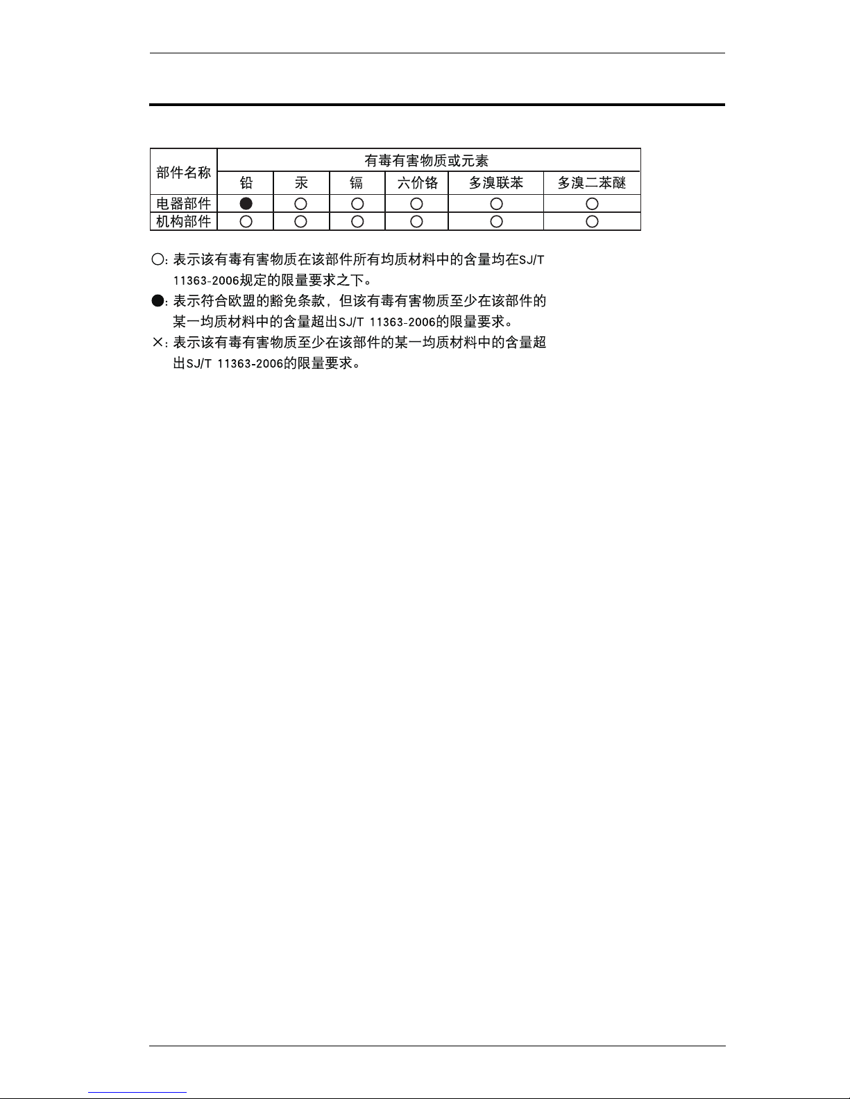
SJ/T 11364-2006
The following contains information that relates to China.
CS1798 / CS17916 User Manual
iv
User Information
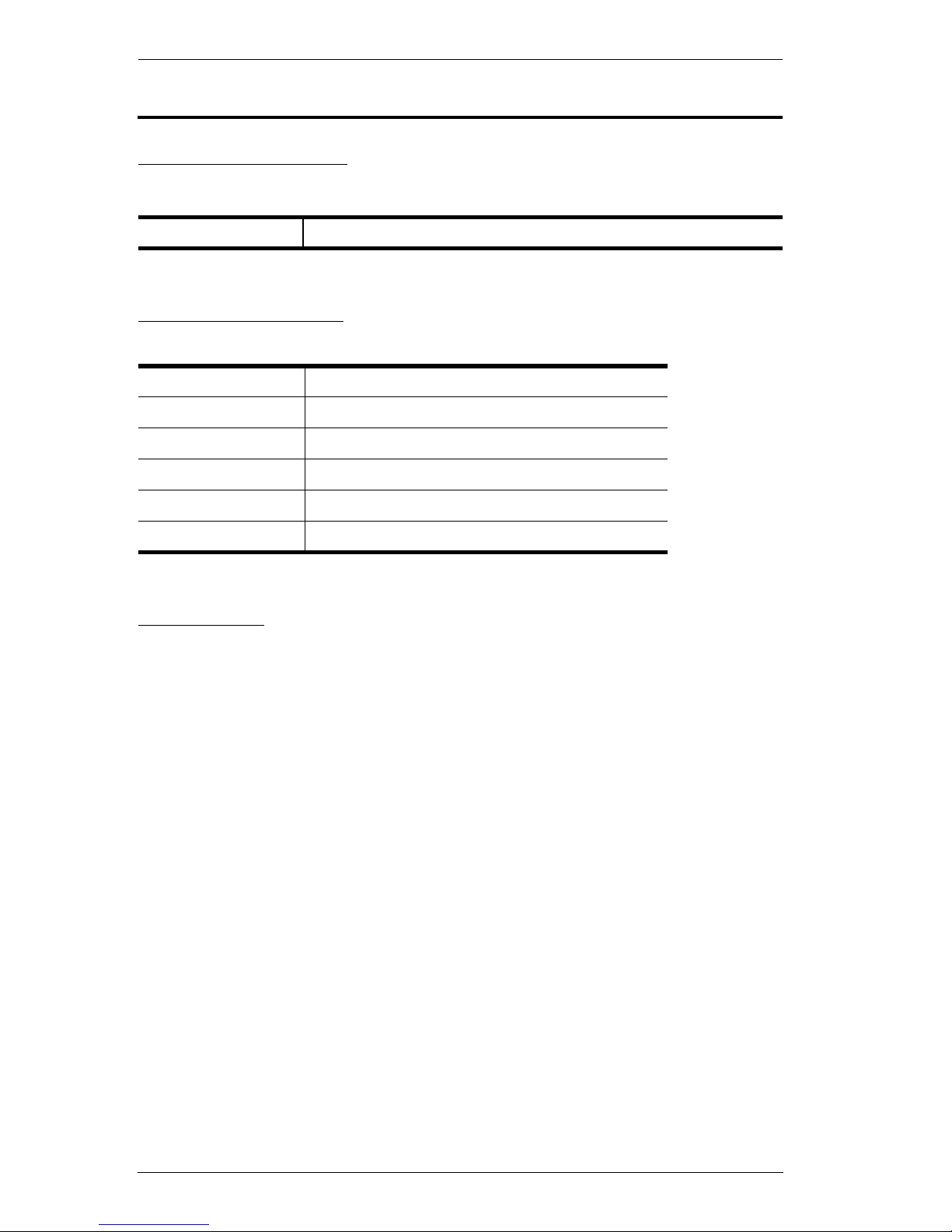
Online Registration
Be sure to register your product at our online support center:
Telephone Support
For telephone support, call this number:
User Notice
All information, documentation, and specifications contained in this manual
are subject to change without prior notification by the manufacturer. The
manufacturer makes no representations or warranties, either expressed or
implied, with respect to the contents hereof and specifically disclaims any
warranties as to merchantability or fitness for any particular purpose. Any of
the manufacturer's software described in this manual is sold or licensed as is.
Should the programs prove defective following their purchase, the buyer (and
not the manufacturer, its distributor, or its dealer), assumes the entire cost of all
necessary servicing, repair and any incidental or consequential damages
resulting from any defect in the software.
The manufacturer of this system is not responsible for any radio and/or TV
interference caused by unauthorized modifications to this device. It is the
responsibility of the user to correct such interference.
The manufacturer is not responsible for any damage incurred in the operation
of this system if the correct operational voltage setting was not selected prior
to operation. PLEASE VERIFY THAT THE VOLTAGE SETTING IS
CORRECT BEFORE USE.
International http://eservice.aten.com
International 886-2-8692-6959
China 86-10-5255-0110
Japan 81-3-5615-5811
Korea 82-2-467-6789
North America 1-888-999-ATEN ext 4988
United Kingdom 44-8-4481-58923

CS1798 / CS17916 User Manual
v
Package Contents
1 CS1798 / CS17916 8/16-port USB HDMI KVM Switch with Rack
Mounting Kit
2 Custom USB HDMI KVM Cable Sets
1 Firmware Upgrade Cable
1 Power Adapter
1 Foot Pad Set (4 pcs)
1 User Instructions*
Check to make sure that all the components are present and that nothing got
damaged in shipping. If you encounter a problem, contact your dealer.
Read this manual thoroughly and follow the installation and operation
procedures carefully to prevent any damage to the unit, and/or any of the
devices connected to it.
* Features may have been added to the CS1798 / CS17916 since this manual
was published. Please visit our website to download the most up-to-date
version.
© Copyright 2015 ATEN® International Co., Ltd.
Manual Date: 2015-08-19
ATEN and the ATEN logo are registered trademarks of ATEN International Co., Ltd. All rights reserved.
All other brand names and trademarks are the registered property of their respective owners.

CS1798 / CS17916 User Manual
vi
Contents
EMC Information. . . . . . . . . . . . . . . . . . . . . . . . . . . . . . . . . . . . . . . . . . . . . ii
RoHS . . . . . . . . . . . . . . . . . . . . . . . . . . . . . . . . . . . . . . . . . . . . . . . . . . . . . ii
SJ/T 11364-2006 . . . . . . . . . . . . . . . . . . . . . . . . . . . . . . . . . . . . . . . . . . . .iii
User Information . . . . . . . . . . . . . . . . . . . . . . . . . . . . . . . . . . . . . . . . . . . . .iv
Online Registration . . . . . . . . . . . . . . . . . . . . . . . . . . . . . . . . . . . . . . . .iv
Telephone Support . . . . . . . . . . . . . . . . . . . . . . . . . . . . . . . . . . . . . . . .iv
User Notice . . . . . . . . . . . . . . . . . . . . . . . . . . . . . . . . . . . . . . . . . . . . . .iv
Package Contents . . . . . . . . . . . . . . . . . . . . . . . . . . . . . . . . . . . . . . . . . . . v
Contents . . . . . . . . . . . . . . . . . . . . . . . . . . . . . . . . . . . . . . . . . . . . . . . . . . .vi
About this Manual . . . . . . . . . . . . . . . . . . . . . . . . . . . . . . . . . . . . . . . . . . . .ix
Conventions . . . . . . . . . . . . . . . . . . . . . . . . . . . . . . . . . . . . . . . . . . . . . . . . x
Product Information . . . . . . . . . . . . . . . . . . . . . . . . . . . . . . . . . . . . . . . . . . x
Chapter 1.
Introduction
Overview. . . . . . . . . . . . . . . . . . . . . . . . . . . . . . . . . . . . . . . . . . . . . . . . . . . 1
Features . . . . . . . . . . . . . . . . . . . . . . . . . . . . . . . . . . . . . . . . . . . . . . . . . . . 3
Requirements . . . . . . . . . . . . . . . . . . . . . . . . . . . . . . . . . . . . . . . . . . . . . . . 5
Console . . . . . . . . . . . . . . . . . . . . . . . . . . . . . . . . . . . . . . . . . . . . . . . . . 5
Computers. . . . . . . . . . . . . . . . . . . . . . . . . . . . . . . . . . . . . . . . . . . . . . . 5
Cables . . . . . . . . . . . . . . . . . . . . . . . . . . . . . . . . . . . . . . . . . . . . . . . . . . 6
Operating Systems . . . . . . . . . . . . . . . . . . . . . . . . . . . . . . . . . . . . . . . . 6
Components . . . . . . . . . . . . . . . . . . . . . . . . . . . . . . . . . . . . . . . . . . . . . . . . 7
Front View CS1798. . . . . . . . . . . . . . . . . . . . . . . . . . . . . . . . . . . . . . . . 7
Front View CS17916. . . . . . . . . . . . . . . . . . . . . . . . . . . . . . . . . . . . . . . 9
Rear View CS1798 . . . . . . . . . . . . . . . . . . . . . . . . . . . . . . . . . . . . . . . 11
Rear View CS17916 . . . . . . . . . . . . . . . . . . . . . . . . . . . . . . . . . . . . . . 12
Chapter 2.
Hardware Setup
Overview. . . . . . . . . . . . . . . . . . . . . . . . . . . . . . . . . . . . . . . . . . . . . . . . . . 13
Installation Types . . . . . . . . . . . . . . . . . . . . . . . . . . . . . . . . . . . . . . . . 13
Before You Begin . . . . . . . . . . . . . . . . . . . . . . . . . . . . . . . . . . . . . . . . . . . 13
Stacking and Rack Mounting . . . . . . . . . . . . . . . . . . . . . . . . . . . . . . . . . . 14
Stacking . . . . . . . . . . . . . . . . . . . . . . . . . . . . . . . . . . . . . . . . . . . . . . . 14
Rack Mounting – Front . . . . . . . . . . . . . . . . . . . . . . . . . . . . . . . . . . . . 15
Rack Mounting – Rear . . . . . . . . . . . . . . . . . . . . . . . . . . . . . . . . . . . . 17
Single Stage Installation . . . . . . . . . . . . . . . . . . . . . . . . . . . . . . . . . . . . . . 19
Single Stage Installation Diagram . . . . . . . . . . . . . . . . . . . . . . . . . . . . 20
Two Stage Cascade . . . . . . . . . . . . . . . . . . . . . . . . . . . . . . . . . . . . . . . . . 21
Three Stage Cascade. . . . . . . . . . . . . . . . . . . . . . . . . . . . . . . . . . . . . . . . 23
Multi-display Installation . . . . . . . . . . . . . . . . . . . . . . . . . . . . . . . . . . . . . . 25
Cable Connections for Multi-display Installation . . . . . . . . . . . . . . . . . 25
Multi-display Installation Diagram . . . . . . . . . . . . . . . . . . . . . . . . . . . . 26

CS1798 / CS17916 User Manual
vii
Grouping Ports into “Vertical” Channels . . . . . . . . . . . . . . . . . . . . . . .27
Channels Diagram. . . . . . . . . . . . . . . . . . . . . . . . . . . . . . . . . . . . . . . . 27
Chapter 3.
Basic Operation
Hot Plugging . . . . . . . . . . . . . . . . . . . . . . . . . . . . . . . . . . . . . . . . . . . . . . .29
Hot Plugging KVM Ports . . . . . . . . . . . . . . . . . . . . . . . . . . . . . . . . . . . 29
Hot Plugging Console Ports . . . . . . . . . . . . . . . . . . . . . . . . . . . . . . . .29
Port Selection . . . . . . . . . . . . . . . . . . . . . . . . . . . . . . . . . . . . . . . . . . . . . .30
Manual Port Switching. . . . . . . . . . . . . . . . . . . . . . . . . . . . . . . . . . . . .30
Port ID Numbering . . . . . . . . . . . . . . . . . . . . . . . . . . . . . . . . . . . . . . . . . . 30
Powering Off and Restarting. . . . . . . . . . . . . . . . . . . . . . . . . . . . . . . . . . .31
Chapter 4.
OSD Operation
OSD Overview . . . . . . . . . . . . . . . . . . . . . . . . . . . . . . . . . . . . . . . . . . . . . 33
Manufacturing Number . . . . . . . . . . . . . . . . . . . . . . . . . . . . . . . . . . . .33
OSD Login. . . . . . . . . . . . . . . . . . . . . . . . . . . . . . . . . . . . . . . . . . . . . .33
OSD Hotkey . . . . . . . . . . . . . . . . . . . . . . . . . . . . . . . . . . . . . . . . . . . . 33
OSD Main Screen . . . . . . . . . . . . . . . . . . . . . . . . . . . . . . . . . . . . . . . .34
OSD Main Screen Headings . . . . . . . . . . . . . . . . . . . . . . . . . . . . . . . .34
OSD Navigation. . . . . . . . . . . . . . . . . . . . . . . . . . . . . . . . . . . . . . . . . .35
OSD Functions . . . . . . . . . . . . . . . . . . . . . . . . . . . . . . . . . . . . . . . . . . . . .35
F1: GOTO . . . . . . . . . . . . . . . . . . . . . . . . . . . . . . . . . . . . . . . . . . . . . . 36
F2: LIST. . . . . . . . . . . . . . . . . . . . . . . . . . . . . . . . . . . . . . . . . . . . . . . .36
F3: SET . . . . . . . . . . . . . . . . . . . . . . . . . . . . . . . . . . . . . . . . . . . . . . . .37
F4: ADM . . . . . . . . . . . . . . . . . . . . . . . . . . . . . . . . . . . . . . . . . . . . . . .39
F5: SKP . . . . . . . . . . . . . . . . . . . . . . . . . . . . . . . . . . . . . . . . . . . . . . . .43
F6: BRC. . . . . . . . . . . . . . . . . . . . . . . . . . . . . . . . . . . . . . . . . . . . . . . . 43
F7: SCAN . . . . . . . . . . . . . . . . . . . . . . . . . . . . . . . . . . . . . . . . . . . . . .44
F8: LOUT. . . . . . . . . . . . . . . . . . . . . . . . . . . . . . . . . . . . . . . . . . . . . . . 45
Chapter 5.
Hotkey Operation
Hotkey Port Control. . . . . . . . . . . . . . . . . . . . . . . . . . . . . . . . . . . . . . . . . . 47
Hotkey Setting Mode. . . . . . . . . . . . . . . . . . . . . . . . . . . . . . . . . . . . . . . . . 47
Invoking HSM . . . . . . . . . . . . . . . . . . . . . . . . . . . . . . . . . . . . . . . . . . .47
Select the Active Port . . . . . . . . . . . . . . . . . . . . . . . . . . . . . . . . . . . . . . . .48
Auto Scan Mode . . . . . . . . . . . . . . . . . . . . . . . . . . . . . . . . . . . . . . . . . . . .49
Invoking Auto Scan: . . . . . . . . . . . . . . . . . . . . . . . . . . . . . . . . . . . . . .49
Skip Mode . . . . . . . . . . . . . . . . . . . . . . . . . . . . . . . . . . . . . . . . . . . . . . . . .50
Keyboard / Mouse Reset. . . . . . . . . . . . . . . . . . . . . . . . . . . . . . . . . . . . . .51
Hotkey Beeper Control . . . . . . . . . . . . . . . . . . . . . . . . . . . . . . . . . . . . . . . 51
Quick Hotkey Control . . . . . . . . . . . . . . . . . . . . . . . . . . . . . . . . . . . . . . . .52
OSD Hotkey Control . . . . . . . . . . . . . . . . . . . . . . . . . . . . . . . . . . . . . . . . .52
Port OS Control. . . . . . . . . . . . . . . . . . . . . . . . . . . . . . . . . . . . . . . . . . . . .53
Restore Default Values . . . . . . . . . . . . . . . . . . . . . . . . . . . . . . . . . . . . . . .53

CS1798 / CS17916 User Manual
viii
USB Reset . . . . . . . . . . . . . . . . . . . . . . . . . . . . . . . . . . . . . . . . . . . . . 53
Hotkey Beeper Control . . . . . . . . . . . . . . . . . . . . . . . . . . . . . . . . . . . . 54
Video DynaSync . . . . . . . . . . . . . . . . . . . . . . . . . . . . . . . . . . . . . . . . . 54
Mouse Emulation Control . . . . . . . . . . . . . . . . . . . . . . . . . . . . . . . . . . 54
HSM Summary Table . . . . . . . . . . . . . . . . . . . . . . . . . . . . . . . . . . . . . . . . 55
Chapter 6.
Keyboard Emulation
Mac Keyboard. . . . . . . . . . . . . . . . . . . . . . . . . . . . . . . . . . . . . . . . . . . . . . 57
Sun Keyboard . . . . . . . . . . . . . . . . . . . . . . . . . . . . . . . . . . . . . . . . . . . . . . 58
Chapter 7.
The Firmware Management Utility
Introduction . . . . . . . . . . . . . . . . . . . . . . . . . . . . . . . . . . . . . . . . . . . . . . . . 59
Downloading the Firmware Upgrade Package . . . . . . . . . . . . . . . . . . 59
Preparation . . . . . . . . . . . . . . . . . . . . . . . . . . . . . . . . . . . . . . . . . . . . . . . . 60
Starting the Upgrade. . . . . . . . . . . . . . . . . . . . . . . . . . . . . . . . . . . . . . . . . 61
Upgrade Succeeded . . . . . . . . . . . . . . . . . . . . . . . . . . . . . . . . . . . . . . . . . 63
Upgrade Failed . . . . . . . . . . . . . . . . . . . . . . . . . . . . . . . . . . . . . . . . . . . . . 63
Firmware Upgrade Recovery . . . . . . . . . . . . . . . . . . . . . . . . . . . . . . . . . . 64
OSD Configuration Backup/Restore . . . . . . . . . . . . . . . . . . . . . . . . . . . . . 65
Backup . . . . . . . . . . . . . . . . . . . . . . . . . . . . . . . . . . . . . . . . . . . . . . . . 65
Restore . . . . . . . . . . . . . . . . . . . . . . . . . . . . . . . . . . . . . . . . . . . . . . . . 66
Safety Instructions . . . . . . . . . . . . . . . . . . . . . . . . . . . . . . . . . . . . . . . . . . 67
General . . . . . . . . . . . . . . . . . . . . . . . . . . . . . . . . . . . . . . . . . . . . . . . . 67
Rack Mounting . . . . . . . . . . . . . . . . . . . . . . . . . . . . . . . . . . . . . . . . . . 69
Technical Support. . . . . . . . . . . . . . . . . . . . . . . . . . . . . . . . . . . . . . . . . . . 70
International . . . . . . . . . . . . . . . . . . . . . . . . . . . . . . . . . . . . . . . . . . . . 70
North America . . . . . . . . . . . . . . . . . . . . . . . . . . . . . . . . . . . . . . . . . . . 70
CS1798 / CS17916 Connection Tables . . . . . . . . . . . . . . . . . . . . . . . . . . 71
Specifications . . . . . . . . . . . . . . . . . . . . . . . . . . . . . . . . . . . . . . . . . . . . . . 72
Administrator Login Failure. . . . . . . . . . . . . . . . . . . . . . . . . . . . . . . . . . . . 73
Factory Default Hotkeys and Settings . . . . . . . . . . . . . . . . . . . . . . . . . . . 74
Limited Warranty. . . . . . . . . . . . . . . . . . . . . . . . . . . . . . . . . . . . . . . . . . . . 74

CS1798 / CS17916 User Manual
ix
About this Manual
This User Manual is provided to help you get the most from your CS1798 /
CS17916 system. It covers all aspects of installation, configuration and
operation. An overview of the information found in the manual is provided
below.
Chapter 1, Introduction, introduces you to the CS1798 / CS17916 system.
Its purpose, features and benefits are presented, and its front and back panel
components are described.
Chapter 2, Hardware Setup, describes how to set up your installation. The
necessary steps for a basic single stage hookup, three-stage cascade, and multidisplay installation are provided.
Chapter 3, Basic Operation, explains the fundamental concepts involved
in operating the CS1798 / CS17916.
Chapter 4, OSD Operation, provides a complete description of the
CS1798 / CS17916's OSD (On Screen Display), and how to work with it.
Chapter 5, Hotkey Operation, details all of the concepts and procedures
involved in the Hotkey operation of your CS1798 / CS17916 installation.
Chapter 6, Keyboard Operation, provides tables that list the PC to Mac
and PC to Sun keyboard emulation mappings.
Chapter 7, The Firmware Upgrade Utility, explains how to use this
utility to upgrade the CS1798 / CS17916's firmware with the latest available
versions and perform an OSD configuration backup/restore.
An Appendix, provides specifications and other technical information
regarding the CS1798 / CS17916.
CS1798 / CS17916 User Manual
x
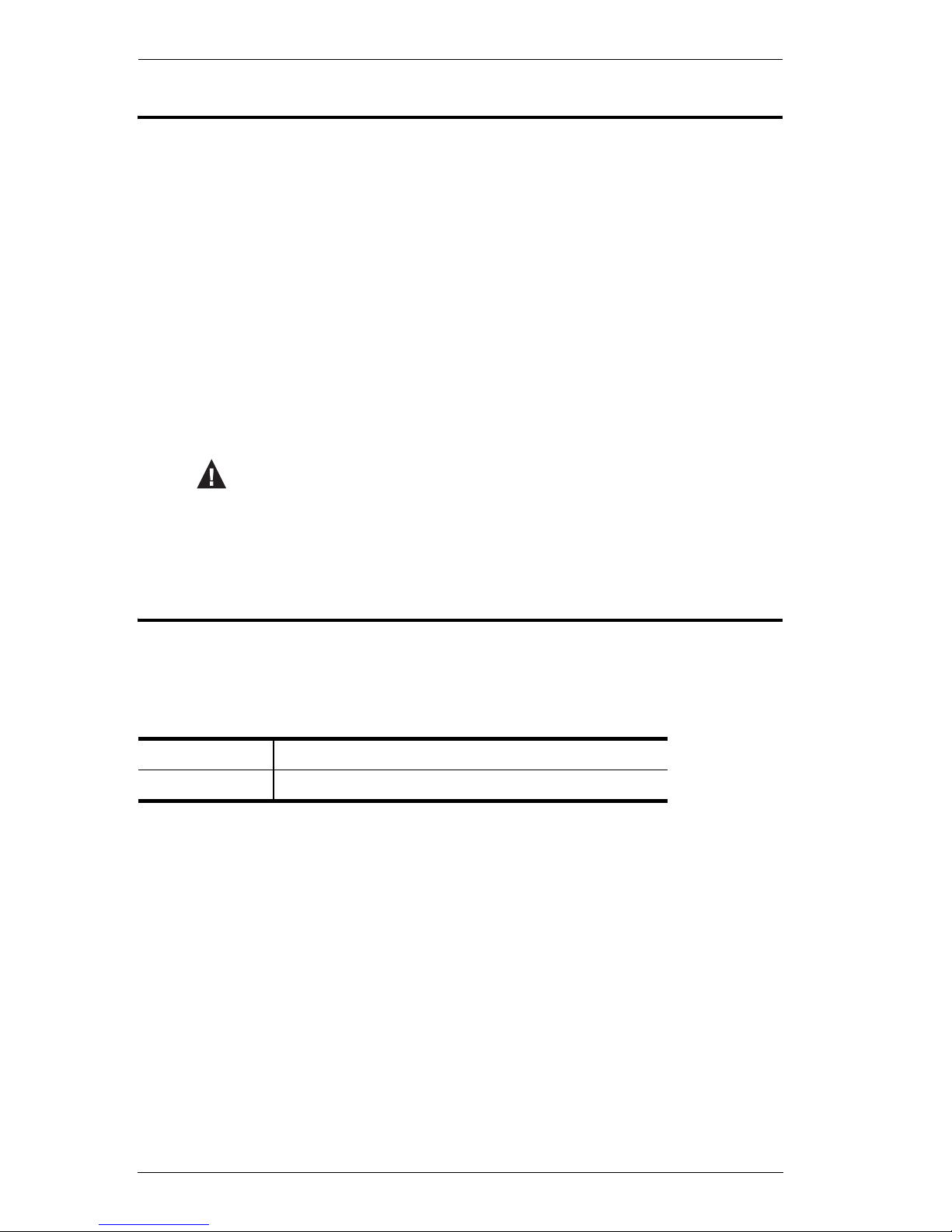
Conventions
This manual uses the following conventions:
Product Information
For information about all ATEN products and how they can help you connect
without limits, visit ATEN on the Web or contact an ATEN Authorized
Reseller. Visit ATEN on the Web for a list of locations and telephone numbers:
Monospaced Indicates text that you should key in.
[ ] Indicates keys you should press. For example, [Enter] means to
press the Enter key. If keys need to be chorded, they appear
together in the same bracket with a plus sign between them:
[Ctrl+Alt].
1. Numbered lists represent procedures with sequential steps.
♦ Bullet lists provide information, but do not involve sequential steps.
→ Indicates selecting the option (on a menu or dialog box, for
example), that comes next. For example, Start
→ Run means to
open the Start menu, and then select Run.
Indicates critical information.
International http://www.aten.com
North America http://www.aten-usa.com

1
Chapter 1
Introduction
Overview
The CS1798 / CS17916 8/16-port USB HDMI KVM Switch is a multi-purpose
appliance that consolidates access and control of up to 8/16 HDMI computers
from a single USB keyboard, USB mouse, and monitor console. The CS1798
/ CS17916 can be cascaded up to three levels – to control up to 512 computers
(CS1798); or two levels – up to 256 computers (CS17916) – all from a single
console.
In addition the CS1798 / CS17916 features multi-display functionality, which
enables the use of standard USB cables to stack up to eight switches in a multidisplay installation where each computer is fitted with multiple video cards.
Furthermore, the CS1798 / CS17916 comes with ATEN’s Video DynaSync
TM
technology, which optimizes display resolution.
There are three convenient methods to access any computer connected to the
installation: (1) using the pushbutton port selection switches located on each
unit's front panel; (2) entering Hotkey combinations from the keyboard; and (3)
selecting from menus provided by the on-screen display (OSD). An Auto Scan
feature also permits automatic scanning and monitoring of all computers on the
installation, one by one.
The CS1798 / CS17916 provides multimedia keyboard support and is audio
enabled. You can listen to the audio output of each computer on two sets of
speakers (on a one at- a-time basis).
Setup is fast and easy; simply plug cables into their appropriate ports. There is
no software to configure, no installation routines, and no incompatibility
problems. Since the CS1798 / CS17916 intercepts keyboard input directly, it
works on multiple operating platforms (PC compatible, Mac*, Sun*, etc.).
Since a single console manages all of the computers on your installation, a
CS1798 / CS17916 KVM switch setup: (1) eliminates the expense of having to
purchase a separate keyboard, monitor, and mouse for each computer; (2) saves
all the space extra components take up; (3) saves on energy costs; and (4)
eliminates the inconvenience and wasted effort involved in constantly moving
from one computer to another.
Note: 1. The CS1798 / CS17916 offers two types of installation – 1)
standalone/cascade; and 2) multi-display – that require different

CS1798 / CS17916 User Manual
2
cabling setups. Therefore, the functions of both types are not
available in one installation.
2. For PC compatible computers. Mac and Sun computers must use the
USB cable connections (see Cables, page 6).

1. Introduction
3
Features
One USB console controls up to eight (CS1798) or sixteen (CS17916)
HDMI interface computers and two additional USB 2.0 devices
HDMI compatible
Cascadable to three levels – control up to 512 computers (CS1798); or two
levels – up to 256 computers (CS17916)*
Multi-display feature – stack up to eight CS1798 / CS17916 units and
display video from up to eight monitors (dual display / triple display / quad
display/ multi-display)
2-port USB 2.0 hub built in*
Computer selection via front panel pushbuttons, hotkeys, and multilingual
on-screen display (OSD)
Independent switching of KVM and USB focus
OSD Backup/Restore feature – enables the administrator to back up the
switch’s configuration and user profile information
Firmware upgradable
Video DynaSync
TM
– exclusive ATEN technology eliminates boot-up
display problems and optimizes resolution when switching between ports
Superior video quality – supports 480i, 480p, 720p, 1080i, and 1080p
(1920 x 1200)
Supports widescreen resolutions
Audio enabled – full bass response provides a rich experience for 2.1
channel surround sound systems
Console audio ports on front panel for easy access
Auto Scan Mode for monitoring all computers
HDCP compatible
Multiplatform support – Windows, Linux, Mac, Sun
Console mouse port emulation/bypass feature supports most mouse
drivers and multifunction mice
Complete keyboard emulation for error-free booting
Mac/Sun keyboard support and emulation*

CS1798 / CS17916 User Manual
4
Multilingual OSD supports English, German, Japanese, Traditional
Chinese, Simplified Chinese, Spanish, Russian, and French
Multilingual keyboard mapping – supports English (US), English (UK),
French, German, Japanese, Korean, Traditional Chinese, and Spanish
Note: 1. CS1798 cascade to CS1798 only.
2. The USB 2.0 hub cannot be accessed through the switch by
computers on the second or third level of a cascaded installation.
3. For PC compatible computers. Mac and Sun computers must be
compatible with USB connections.
4. PC keyboard combinations emulate Mac/Sun keyboards; Mac/Sun
keyboards work only with their own computers.

1. Introduction
5
Requirements
Console
An HDMI compatible monitor capable of the highest possible resolution
that you will be using on any computer in the installation
Note: For multi-display installations, multiple monitors are required. See
Multi-display Installation, page 25, for details.
A USB mouse
A USB keyboard
Speakers (optional)
Computers
The following equipment must be available on each computer:
An HDMI card
Note: 1. The quality of the display is affected by the quality of the HDMI
display card. For best results, we recommend you purchase a high
quality product.
2. For multi-display installations, the computers require multiple
HDMI cards. See Multi-display Installation, page 25, for details.
Type A USB port
Speaker ports (optional)

CS1798 / CS17916 User Manual
6
Cables
Only custom USB HDMI KVM cable sets, which are specifically designed
to work with this switch, may be used to link to the computers. Two cable
sets are provided with this package.
Note: The quality of the display is affected by the quality and length of the
cables. If you need additional cable sets, please contact your dealer
to purchase the appropriate ones for your switch.
For multi-display installations, standard USB Type A to USB Type B
cables and standard HDMI cables are also required.
Note: The CS1798 / CS17916 supports speaker ports only. Do not connect
the microphone connector from the KVM cable sets.
Operating Systems
Note: 1. Supports Linux Kernel 2.6 and higher.
2. The CS1798 / CS17916 has a built-in USB 2.0 hub, and does not
support PCs or operating systems that do not support USB 2.0.
Type Length Part Number
USB HDMI KVM Cable 1.8 m 2L-7D02UH
OS Version
Windows 2000 / XP / 2003 / 2008 / Vista / 7 / Windows 8
Linux RedHat 9.0 and higher
SuSE 10 / 11.1 and higher
Debian 3.1 / 4.0
Ubuntu 7.04 / 7.10
UNIX AIX 4.3 and higher
FreeBSD 5.5 and higher
Sun Solaris 8 and higher
Novell Netware 6.0 and higher
Mac OS 9 to 10.6 (Snow Leopard)
1. Introduction
7
Components
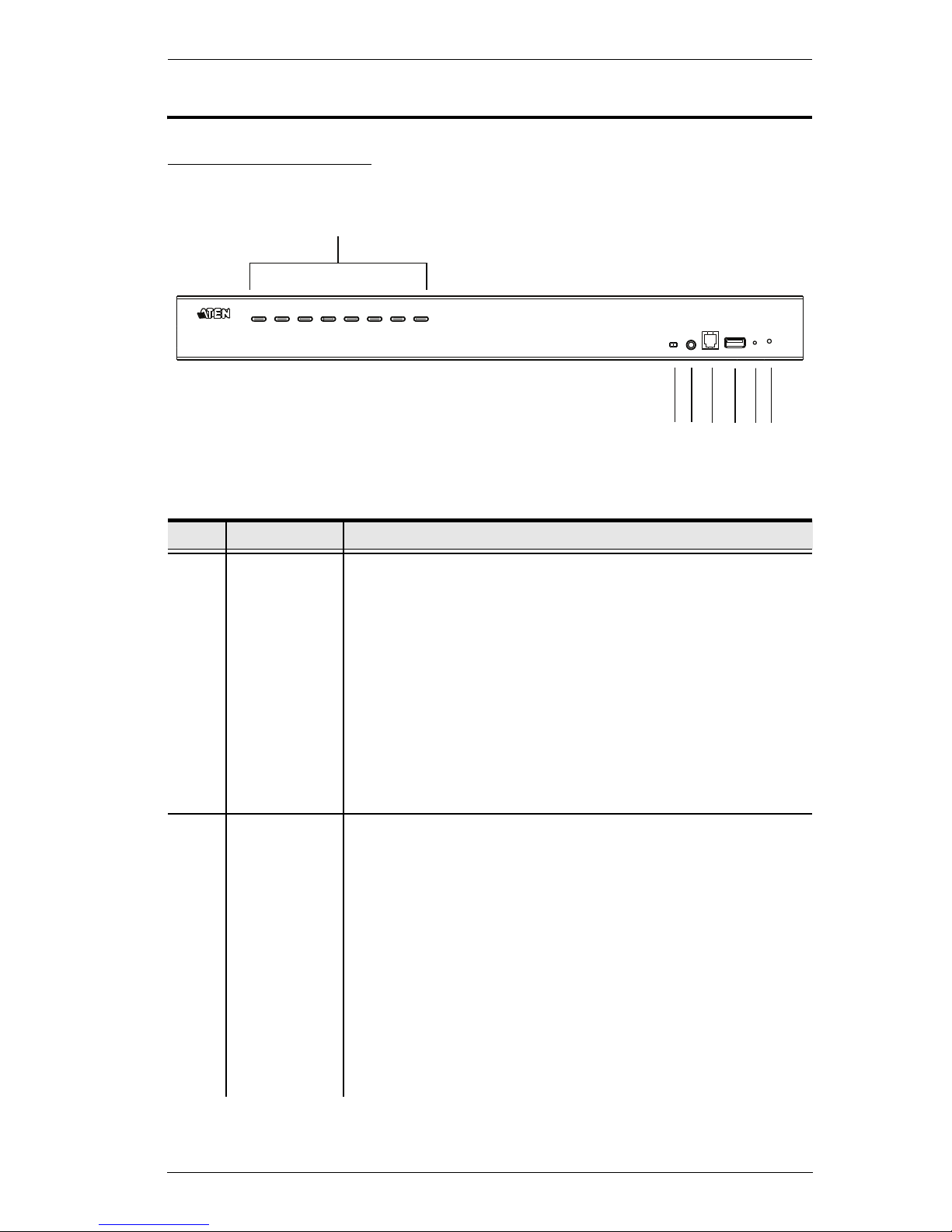
Front View CS1798
No. Component Description
1 Port Selection
Pushbuttons
For manual port selection (see Port Selection, page 30, also):
Press a port selection pushbutton for less than two seconds to bring
the KVM, USB hub, and audio focus to the computer attached to its
corresponding port.
Press a pushbutton for longer than two seconds to bring the KVM
and audio focus* to the computer attached to its corresponding port.
Press pushbuttons 1 and 2 simultaneously for 2 seconds to start
Auto Scan Mode*. See Auto Scan Mode, page 49, for details.
Press pushbuttons 7 and 8 simultaneously for 2 seconds to perform
a keyboard and mouse reset. See Keyboard / Mouse Reset,
page 51, also
Note:
Enable mouse emulation for independent switching (see
page 42).
2 Port LEDs
The Port LEDs are built into the Port Selection Switches. The left ones
are the KVM Port LEDs; the right ones are the USB LEDs:
KVM
Lights DIM ORANGE to indicate that the computer attached to the
corresponding port is up and running (On Line).
Flashes to indicate that Firmware Upgrade mode is in effect.
Changes to BRIGHT ORANGE to indicate that the computer
attached to its corresponding port is the one that has the KVM focus
(Selected).
Flashes to indicate that the computer attached to its corresponding
port is being accessed under Auto Scan mode.
USB
Lights GREEN to indicate that the computer attached to its corre-
sponding port is the one that has access to the USB peripherals.
4
3
1 & 2
5
6
7
8
CS1798 / CS17916 User Manual
8
3 Firmware
Upgrade
Recovery
Switch
During normal operation and while performing a firmware
upgrade, this switch should be in the NORMAL position. If a
firmware upgrade operation does not complete successfully,
this switch is used to perform a firmware upgrade recovery.
See Firmware Upgrade Recovery, page 64, for details.
4 Audio Port The cables from your main speakers plug in here. The
speakers plugged in here have priority over those in the rear
panel.
5 Firmware
Upgrade Port
The firmware upgrade cable that transfers the firmware
upgrade data from the administrator's computer to the CS1798
/ CS17916 plugs into this RJ-11 connector.
6 USB 2.0 Hub USB 2.0 peripherals (printers, scanners, etc.) can plug into this
port (this may require an extra power adapter).
Note: The USB 2.0 hub cannot be accessed through the
switch by computers on the second or third level of a cascaded
installation.
7 Reset Switch Pressing this switch performs a system reset. When the
system is reset, the switch beeps, and the port LEDs flash in
succession until the reset is complete. After the reset is
complete you can login again.
Note: This switch is recessed and must be pushed with a
small object, such as the end of a paper clip or a ballpoint pen.
8 Power LED Lights to indicate that the switch is powered up and ready to
operate.
No. Component Description
1. Introduction
9
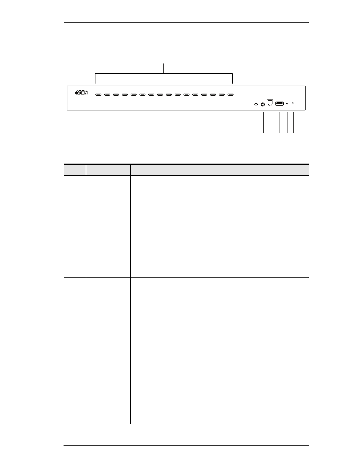
Front View CS17916
No. Component Description
1 Port Selection
Pushbuttons
For manual port selection (see Port Selection, page 30, also):
Press a port selection pushbutton for less than two seconds to bring
the KVM, USB hub, and audio focus to the computer attached to its
corresponding port.
Press a pushbutton for longer than two seconds to bring the KVM
and audio focus* to the computer attached to its corresponding port.
Press pushbuttons 1 and 2 simultaneously for 2 seconds to start
Auto Scan Mode*. See Auto Scan Mode, page 49, for details.
Press pushbuttons 15 and 16 simultaneously for 2 seconds to per-
form a keyboard and mouse reset. See Keyboard / Mouse Reset,
page 51, also
Note: Enable mouse emulation for independent switching (see
page 42).
2 Port LEDs The Port LEDs are built into the Port Selection Switches. The
left ones are the KVM Port LEDs; the right ones are the USB
LEDs:
KVM
Lights DIM ORANGE to indicate that the computer attached to the
corresponding port is up and running (On Line).
Flashes to indicate that Firmware Upgrade mode is in effect.
Changes to BRIGHT ORANGE to indicate that the computer
attached to its corresponding port is the one that has the KVM focus
(Selected).
Flashes to indicate that the computer attached to its corresponding
port is being accessed under Auto Scan mode.
USB
Lights GREEN to indicate that the computer attached to its corre-
sponding port is the one that has access to the USB peripherals.
Note: The USB 2.0 hub cannot be accessed through the
switch by computers on the second or third level of a cascaded
installation.
1 & 2
4
3
5
6
7
8

CS1798 / CS17916 User Manual
10
3 Firmware
Upgrade
Recovery
Switch
During normal operation and while performing a firmware
upgrade, this switch should be in the NORMAL position. If a
firmware upgrade operation does not complete successfully,
this switch is used to perform a firmware upgrade recovery.
See Firmware Upgrade Recovery, page 64, for details.
4 Audio Port The cables from your main speakers plug in here. The
speakers plugged in here have priority over those in the rear
panel.
5 Firmware
Upgrade Port
The firmware upgrade cable that transfers the firmware
upgrade data from the administrator's computer to the CS1798
/ CS17916 plugs into this RJ-11 connector.
6 USB 2.0 Hub USB 2.0 peripherals (printers, scanners, etc.) can plug into this
port (this may require an extra power adapter).
Note: The USB 2.0 hub cannot be accessed through the
switch by computers on the second or third level of a cascaded
installation.
7 Reset Switch Pressing this switch performs a system reset. When the
system is reset, the switch beeps, and the port LEDs flash in
succession until the reset is complete. After the reset is
complete you can login again.
Note: This switch is recessed and must be pushed with a
small object, such as the end of a paper clip or a ballpoint pen.
8 Power LED Lights to indicate that the switch is powered up and ready to
operate.
No. Component Description
1. Introduction
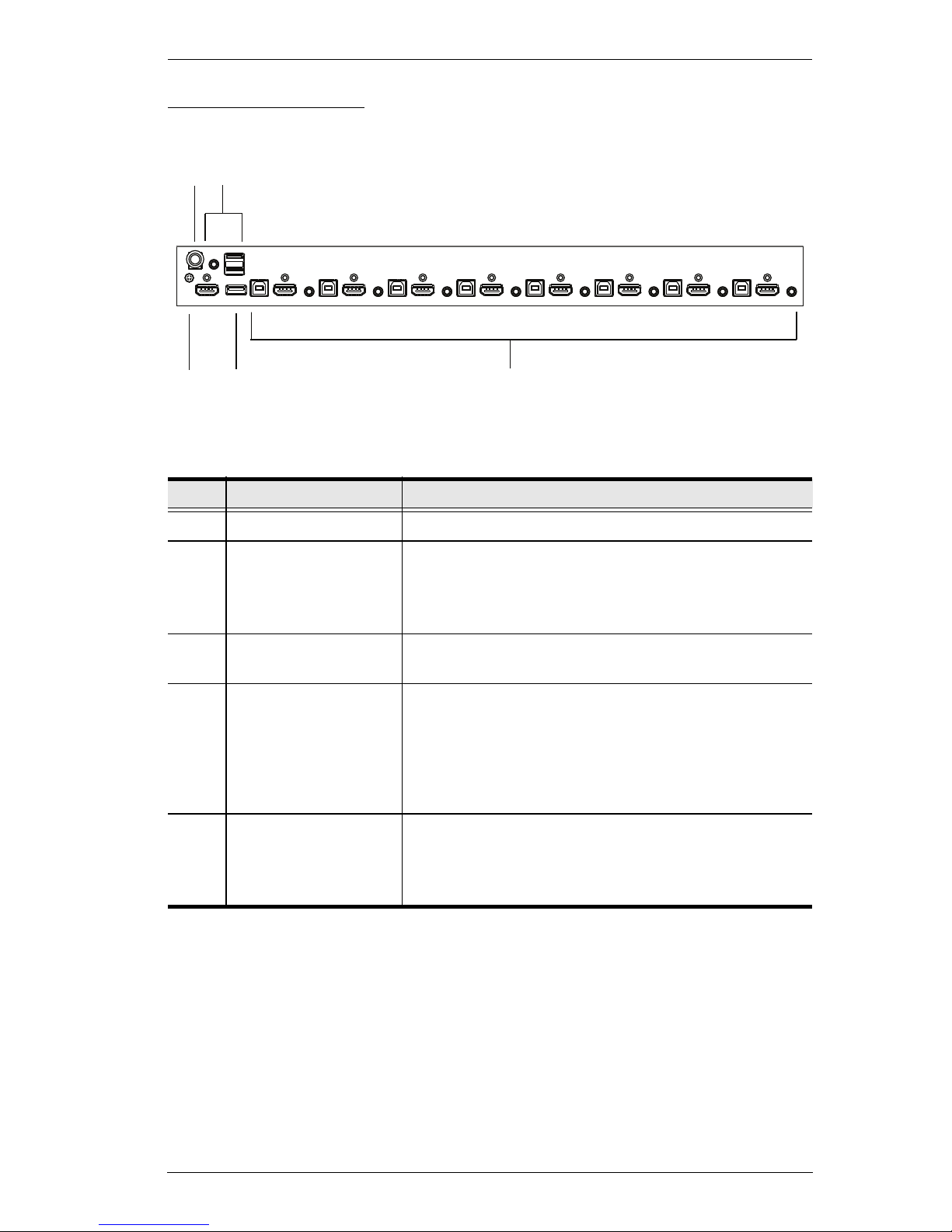
11
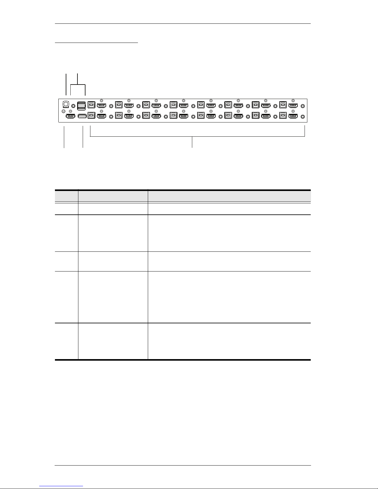
Rear View CS1798
No. Component Description
1 Power Jack The power adapter cable plugs in here.
2 Console Port Section The cables from your console HDMI monitor, USB
keyboard, USB mouse, and speakers plug in here.
Each connector is marked with an appropriate icon to
indicate itself.
3 Grounding Terminal The grounding wire used to ground the CS1798 /
CS17916 attaches here. (Optional)
4 USB 2.0 Hub USB 2.0 peripherals (printers, scanners, etc.) can plug
into this port (this may require an extra power
adapter).
Note: The USB 2.0 hub cannot be accessed through
the switch by computers on the second or third level of
a cascaded installation.
5 KVM Port Sections The cables that link the switch to your computers plug
in here. Each KVM port section is comprised of a
speaker jack, a USB type B socket, and HDMI
connector with screw lock.
4
3
5
1
2
CS1798 / CS17916 User Manual
12
Rear View CS17916
No. Component Description
1 Power Jack The power adapter cable plugs in here.
2 Console Port Section The cables from your console HDMI monitor, USB
keyboard, USB mouse, and speakers plug in here.
Each connector is marked with an appropriate icon to
indicate itself.
3 Grounding Terminal The grounding wire used to ground the CS1798 /
CS17916 attaches here. (Optional)
4 USB 2.0 Hub USB 2.0 peripherals (printers, scanners, etc.) can plug
into this port (this may require an extra power
adapter).
Note: The USB 2.0 hub cannot be accessed through
the switch by computers on the second or third level of
a cascaded installation.
5 KVM Port Sections The cables that link the switch to your computers plug
in here. Each KVM port section is comprised of a
speaker jack, a USB type B socket, and HDMI
connector with screw lock.
5
4
3
1
2
13
Chapter 2
Hardware Setup
Overview
For convenience and flexibility that allows mixing multiple platforms, the
CS1798 / CS17916 design utilizes custom USB HDMI KVM cables that serve
as intermediaries between the switch and the connected computers (refer to the
installation diagram on page 20).
A separate custom USB HDMI KVM cable is required for each computer
connection. The custom KVM cables are listed under Cables, on page 6.
Consult your dealer to find out which custom KVM cables best fit your needs.
Installation Types
The CS1798 / CS17916 offers two types of installation – 1) standalone/
cascade; and 2) multi-display – that require different cabling setups. Therefore,
the functions of both types are not available in one installation. See the
following sections in this chapter for details about the different cabling
requirements.
Before You Begin
1. Important safety information regarding the placement of this
device is provided on page 67. Please review it before
proceeding.
2. Make sure that power to all devices that you will be installing
has been turned off. You must unplug the power cords of any
computers that have the Keyboard Power On function.
CS1798 / CS17916 User Manual
14
Stacking and Rack Mounting
The CS1798 / CS17916 can be stacked on the desktop or rack mounted at the
front or rear of the rack. The following sections take you through the
procedures for each method.
Note: 1. Allow at least 5.1 cm on each side for adequate ventilation and
12.7 cm at the rear for power cord and cable clearance.
2. The standard rack mounting kit does not include screws or cage nuts.
If you need additional screws or cage nuts, contact your rack dealer.
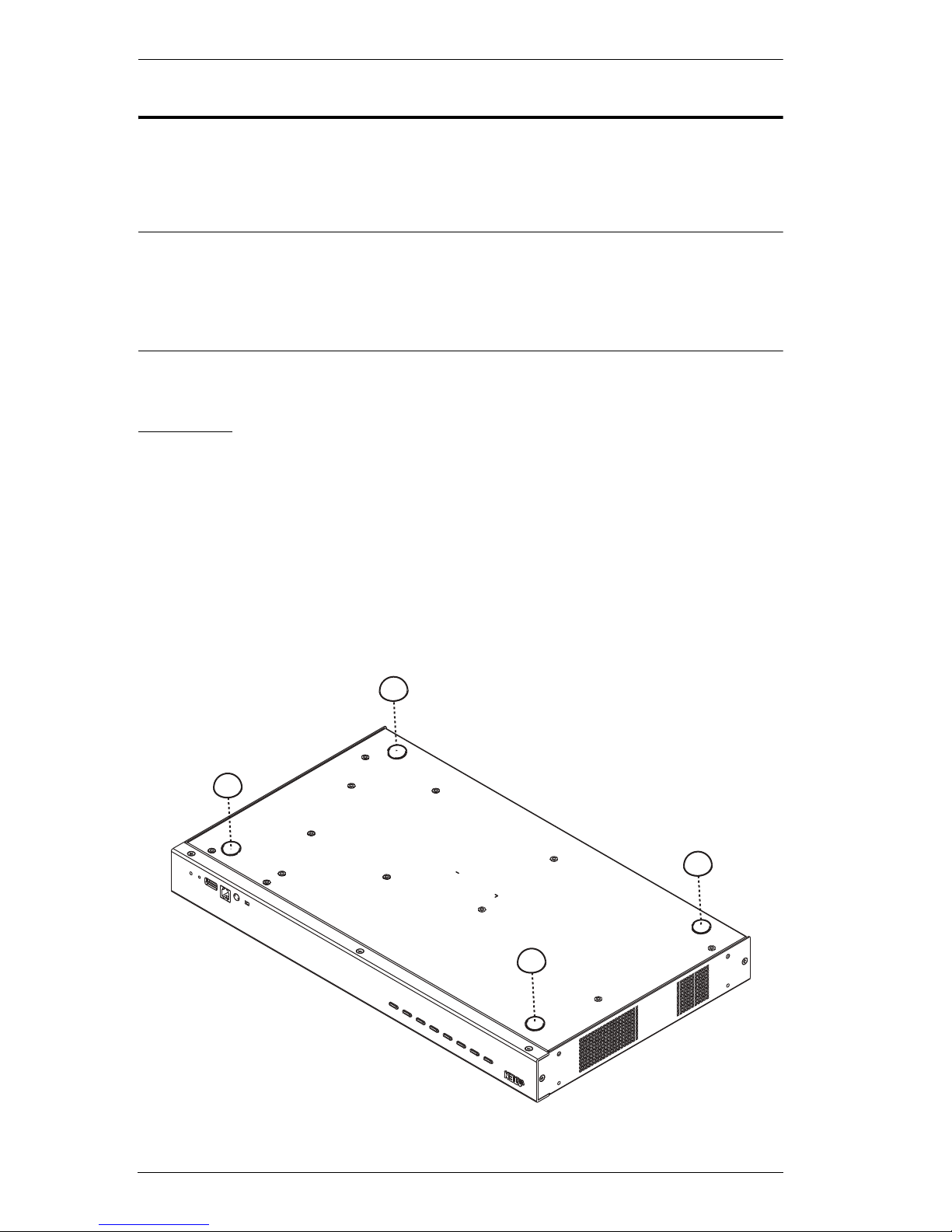
Stacking
The CS1798 / CS17916 can be placed on any level surface that can safely
support its weight and the weight of the attached cables. Make sure that the
surface is clean and free of any materials that can block the exhaust vents or
otherwise interfere with normal operation of the switch.
To place the CS1798 / CS17916, or to stack units if you are cascading them,
remove the backing material from the bottom of the rubber feet that came with
this package, and stick them onto the bottom panel at the corners, as shown in
the diagram, below:

2. Hardware Setup
15
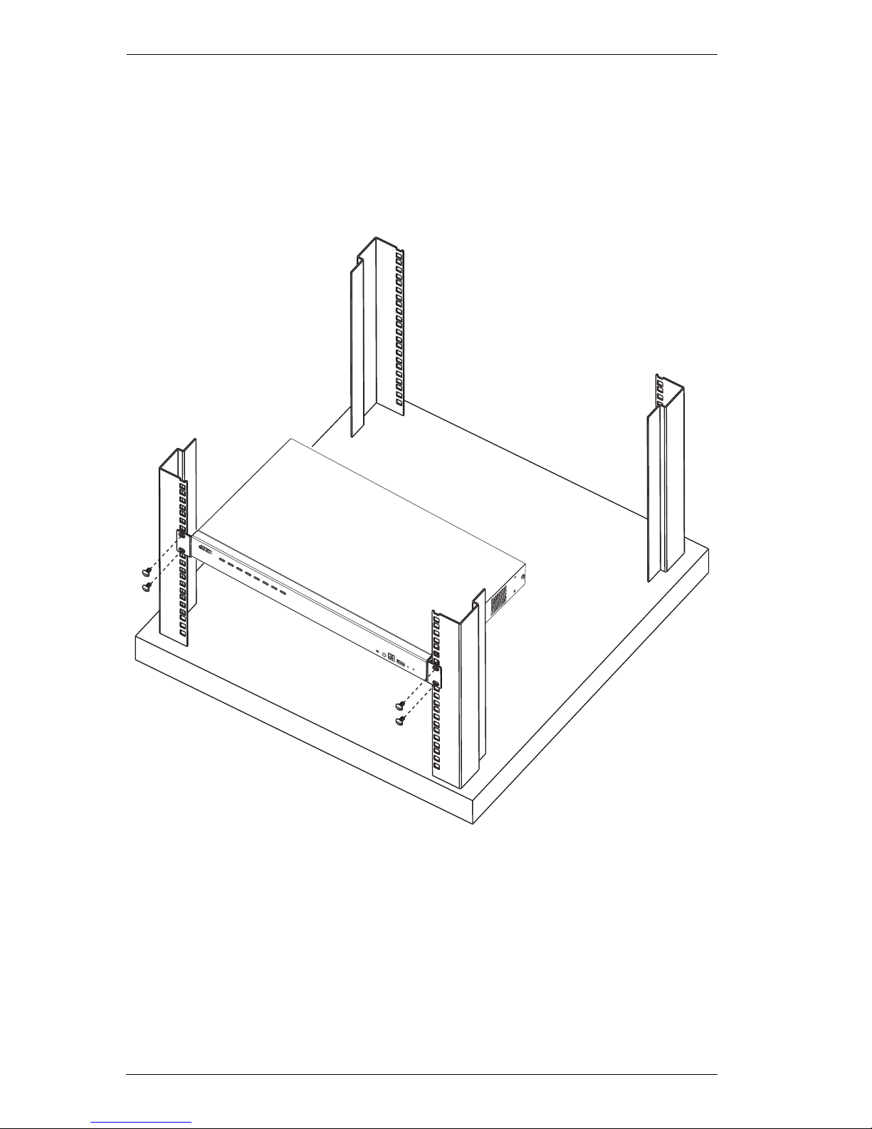
Rack Mounting – Front
1. Remove the screws, one each from the left and right sides of the switch
near the front of the switch.
2. Use the M3 x 8 Phillips hex head screws supplied with the rack mounting kit
to screw the rack mounting brackets into the sides near the front of the unit.
(Continues on next page.)
CS1798 / CS17916 User Manual
16
(Continued from previous page.)
3. Place the KVM switch in the rack. Position it so that the holes in the
mounting brackets line up with the holes in the rack. Secure the mounting
brackets to the front of the rack.
 Loading...