


KVM over IP
CS1708i / CS1716i
Full HD Version
User Manual
www.aten.com

CS1708i / CS1716i User Manual
EMC Information
FEDERAL COMMUNICATIONS COMMISSION INTERFERENCE
STATEMENT: This equipment has been tested and found to comply with the
limits for a Class A digital device, pursuant to Part 15 of the FCC Rules. These
limits are designed to provide reasonable protection against harmful
interference when the equipment is operated in a commercial environment.
This equipment generates, uses, and can radiate radio frequency energy and, if
not installed and used in accordance with the instruction manual, may cause
harmful interference to radio communications. Operation of this equipment in
a residential area is likely to cause harmful interference in which case the user
will be required to correct the interference at his own expense.
The device complies with Part 15 of the FCC Rules. Operation is subject to the
following two conditions: (1) this device may not cause harmful interference,
and (2) this device must accept any interference received, including
interference that may cause undesired operation.
FCC Caution: Any changes or modifications not expressly approved by the
party responsible for compliance could void the user's authority to operate this
equipment.
Warning: Operation of this equipment in a residential environment could
cause radio interference.
KCC Statement
RoHS
This product is RoHS compliant.
ii

CS1708i / CS1716i User Manual
User Information
Online Registration
Be sure to register your product at our online support center:
International http://support.aten.com
North America http://www.aten-usa.com/product_registration
Telephone Support
For telephone support, call this number:
International 886-2-8692-6959
China 86-400-810-0-810
Japan 81-3-5615-5811
Korea 82-2-467-6789
North America 1-888-999-ATEN ext 4988
1-949-428-1111
User Notice
All information, documentation, and specifications contained in this manual
are subject to change without prior notification by the manufacturer. The
manufacturer makes no representations or warranties, either expressed or
implied, with respect to the contents hereof and specifically disclaims any
warranties as to merchantability or fitness for any particular purpose. Any of
the manufacturer's software described in this manual is sold or licensed as is.
Should the programs prove defective following their purchase, the buyer (and
not the manufacturer, its distributor, or its dealer), assumes the entire cost of all
necessary servicing, repair and any incidental or consequential damages
resulting from any defect in the software.
The manufacturer of this system is not responsible for any radio and/or TV
interference caused by unauthorized modifications to this device. It is the
responsibility of the user to correct such interference.
The manufacturer is not responsible for any damage incurred in the operation
of this system if the correct operational voltage setting was not selected prior
to operation. PLEASE VERIFY THAT THE VOLTAGE SETTING IS
CORRECT BEFORE USE.
iii

CS1708i / CS1716i User Manual
© Copyright 2020 ATEN® International Co., Ltd.
Manual Date: 2020-10-15
ATEN and the ATEN logo are registered trademarks of ATEN International Co., Ltd. All rights reserved.
All other brand names and trademarks are the registered property of their respective owners.
Package Contents
The CS1708i / CS1716i package consists of:
1 CS1708i / CS1716i KVM Switch
2 Custom KVM Cable Sets (1 x PS/2; 1 x USB)
1 Console Cable
1 Firmware Upgrade Cable
1 Mounting Kit
1 Foot Pad Set (4 pcs)
1 Power Adapter
1 User Instructions*
Check to make sure that all the components are present and that nothing got
damaged in shipping. If you encounter a problem, contact your dealer.
Read this manual thoroughly and follow the installation and operation
procedures carefully to prevent any damage to the unit, and/or any of the
devices connected to it.
* Features may have been added to the CS1708i / CS1716i since this manual
was published. Please visit our website to download the most up-to-date
version of the manual.
iv

CS1708i / CS1716i User Manual
Contents
EMC Information . . . . . . . . . . . . . . . . . . . . . . . . . . . . . . . . . . . . . . . . . . . . . ii
RoHS. . . . . . . . . . . . . . . . . . . . . . . . . . . . . . . . . . . . . . . . . . . . . . . . . . . . . . ii
User Information . . . . . . . . . . . . . . . . . . . . . . . . . . . . . . . . . . . . . . . . . . . . .iii
Online Registration . . . . . . . . . . . . . . . . . . . . . . . . . . . . . . . . . . . . . . . .iii
Telephone Support . . . . . . . . . . . . . . . . . . . . . . . . . . . . . . . . . . . . . . . .iii
User Notice . . . . . . . . . . . . . . . . . . . . . . . . . . . . . . . . . . . . . . . . . . . . . .iii
Package Contents. . . . . . . . . . . . . . . . . . . . . . . . . . . . . . . . . . . . . . . . . . . iv
About this Manual . . . . . . . . . . . . . . . . . . . . . . . . . . . . . . . . . . . . . . . . . . . xii
Overview . . . . . . . . . . . . . . . . . . . . . . . . . . . . . . . . . . . . . . . . . . . . . . . xii
Terminology. . . . . . . . . . . . . . . . . . . . . . . . . . . . . . . . . . . . . . . . . . . . .xiii
Conventions . . . . . . . . . . . . . . . . . . . . . . . . . . . . . . . . . . . . . . . . . . . .xiv
Product Information. . . . . . . . . . . . . . . . . . . . . . . . . . . . . . . . . . . . . . .xiv
Chapter 1.
Introduction
Overview . . . . . . . . . . . . . . . . . . . . . . . . . . . . . . . . . . . . . . . . . . . . . . . . . . . 1
Features . . . . . . . . . . . . . . . . . . . . . . . . . . . . . . . . . . . . . . . . . . . . . . . . . . . 3
Requirements . . . . . . . . . . . . . . . . . . . . . . . . . . . . . . . . . . . . . . . . . . . . . . .5
General . . . . . . . . . . . . . . . . . . . . . . . . . . . . . . . . . . . . . . . . . . . . . . . . .5
Console . . . . . . . . . . . . . . . . . . . . . . . . . . . . . . . . . . . . . . . . . . . . . . . . .5
Computers. . . . . . . . . . . . . . . . . . . . . . . . . . . . . . . . . . . . . . . . . . . . . . .5
Cables . . . . . . . . . . . . . . . . . . . . . . . . . . . . . . . . . . . . . . . . . . . . . . . . . . 6
Operating Systems . . . . . . . . . . . . . . . . . . . . . . . . . . . . . . . . . . . . . . . .6
Components . . . . . . . . . . . . . . . . . . . . . . . . . . . . . . . . . . . . . . . . . . . . . . . .7
Front Panel . . . . . . . . . . . . . . . . . . . . . . . . . . . . . . . . . . . . . . . . . . . . . . 7
CS1708i . . . . . . . . . . . . . . . . . . . . . . . . . . . . . . . . . . . . . . . . . . . . . .7
CS1716i . . . . . . . . . . . . . . . . . . . . . . . . . . . . . . . . . . . . . . . . . . . . . .7
Rear Panel . . . . . . . . . . . . . . . . . . . . . . . . . . . . . . . . . . . . . . . . . . . . . .9
CS1708i . . . . . . . . . . . . . . . . . . . . . . . . . . . . . . . . . . . . . . . . . . . . . .9
CS1716i . . . . . . . . . . . . . . . . . . . . . . . . . . . . . . . . . . . . . . . . . . . . . .9
Chapter 2.
Hardware Setup
Overview . . . . . . . . . . . . . . . . . . . . . . . . . . . . . . . . . . . . . . . . . . . . . . . . . . 11
Before You Begin . . . . . . . . . . . . . . . . . . . . . . . . . . . . . . . . . . . . . . . . . . . 11
Stacking and Rack Mounting . . . . . . . . . . . . . . . . . . . . . . . . . . . . . . . . . . 12
Stacking. . . . . . . . . . . . . . . . . . . . . . . . . . . . . . . . . . . . . . . . . . . . . . . .12
Rack Mounting – Front . . . . . . . . . . . . . . . . . . . . . . . . . . . . . . . . . . . .13
Rack Mounting – Rear. . . . . . . . . . . . . . . . . . . . . . . . . . . . . . . . . . . . .15
Single Station Installation . . . . . . . . . . . . . . . . . . . . . . . . . . . . . . . . . . . . .17
Cable Connection Diagrams . . . . . . . . . . . . . . . . . . . . . . . . . . . . . . . . . . . 19
Daisy Chaining . . . . . . . . . . . . . . . . . . . . . . . . . . . . . . . . . . . . . . . . . . . . . 20
Powering Up . . . . . . . . . . . . . . . . . . . . . . . . . . . . . . . . . . . . . . . . . . . .20
Chapter 3.
v

CS1708i / CS1716i User Manual
Basic Operation
Port Selection . . . . . . . . . . . . . . . . . . . . . . . . . . . . . . . . . . . . . . . . . . . . . . 23
Manual . . . . . . . . . . . . . . . . . . . . . . . . . . . . . . . . . . . . . . . . . . . . . . . . 23
OSD/GUI. . . . . . . . . . . . . . . . . . . . . . . . . . . . . . . . . . . . . . . . . . . . . . . 23
Keyboard Hotkeys. . . . . . . . . . . . . . . . . . . . . . . . . . . . . . . . . . . . . . . . 23
Hot Plugging . . . . . . . . . . . . . . . . . . . . . . . . . . . . . . . . . . . . . . . . . . . . . . . 24
Hot Plugging Stations . . . . . . . . . . . . . . . . . . . . . . . . . . . . . . . . . . . . . 24
Hot Plugging KVM Ports . . . . . . . . . . . . . . . . . . . . . . . . . . . . . . . . . . . 24
Hot Plugging Console Ports . . . . . . . . . . . . . . . . . . . . . . . . . . . . . . . . 24
Port ID Numbering . . . . . . . . . . . . . . . . . . . . . . . . . . . . . . . . . . . . . . . . . . 25
Powering Off and Restarting. . . . . . . . . . . . . . . . . . . . . . . . . . . . . . . . . . . 25
USB Peripheral Devices . . . . . . . . . . . . . . . . . . . . . . . . . . . . . . . . . . . . . . 26
Chapter 4.
OSD Operation
Overview. . . . . . . . . . . . . . . . . . . . . . . . . . . . . . . . . . . . . . . . . . . . . . . . . . 27
Manufacturing Number . . . . . . . . . . . . . . . . . . . . . . . . . . . . . . . . . . . . 28
OSD Main Screen . . . . . . . . . . . . . . . . . . . . . . . . . . . . . . . . . . . . . . . . 28
OSD Navigation . . . . . . . . . . . . . . . . . . . . . . . . . . . . . . . . . . . . . . . . . . . . 29
OSD Main Screen Headings. . . . . . . . . . . . . . . . . . . . . . . . . . . . . . . . 29
OSD Functions . . . . . . . . . . . . . . . . . . . . . . . . . . . . . . . . . . . . . . . . . . . . . 30
F1: GOTO . . . . . . . . . . . . . . . . . . . . . . . . . . . . . . . . . . . . . . . . . . . . . . 30
F2: LIST . . . . . . . . . . . . . . . . . . . . . . . . . . . . . . . . . . . . . . . . . . . . . . . 31
F3: SET. . . . . . . . . . . . . . . . . . . . . . . . . . . . . . . . . . . . . . . . . . . . . . . . 32
F4: ADM . . . . . . . . . . . . . . . . . . . . . . . . . . . . . . . . . . . . . . . . . . . . . . . 34
F5: SKP. . . . . . . . . . . . . . . . . . . . . . . . . . . . . . . . . . . . . . . . . . . . . . . . 36
F6: BRC . . . . . . . . . . . . . . . . . . . . . . . . . . . . . . . . . . . . . . . . . . . . . . . 37
F7: SCAN . . . . . . . . . . . . . . . . . . . . . . . . . . . . . . . . . . . . . . . . . . . . . . 38
F8: LOUT . . . . . . . . . . . . . . . . . . . . . . . . . . . . . . . . . . . . . . . . . . . . . . 39
Hotkey Operation . . . . . . . . . . . . . . . . . . . . . . . . . . . . . . . . . . . . . . . . . . . 40
Overview . . . . . . . . . . . . . . . . . . . . . . . . . . . . . . . . . . . . . . . . . . . . . . . 40
Invoking Hotkey Mode. . . . . . . . . . . . . . . . . . . . . . . . . . . . . . . . . . . . . 41
Hotkey Port Control. . . . . . . . . . . . . . . . . . . . . . . . . . . . . . . . . . . . . . . 42
Hotkey Configuration Operations . . . . . . . . . . . . . . . . . . . . . . . . . . . . 45
Hotkey Beeper Control . . . . . . . . . . . . . . . . . . . . . . . . . . . . . . . . . 45
Toggling the Hotkey Invocation Keys . . . . . . . . . . . . . . . . . . . . . . 45
Set USB Speed . . . . . . . . . . . . . . . . . . . . . . . . . . . . . . . . . . . . . . . 46
Setting the Port Operating System . . . . . . . . . . . . . . . . . . . . . . . . 47
Restore Default Values . . . . . . . . . . . . . . . . . . . . . . . . . . . . . . . . . 47
Hotkey Summary Table. . . . . . . . . . . . . . . . . . . . . . . . . . . . . . . . . . . . 48
Chapter 5.
Logging In
Overview. . . . . . . . . . . . . . . . . . . . . . . . . . . . . . . . . . . . . . . . . . . . . . . . . . 49
Browser Login. . . . . . . . . . . . . . . . . . . . . . . . . . . . . . . . . . . . . . . . . . . . . . 50
Windows Client AP Login . . . . . . . . . . . . . . . . . . . . . . . . . . . . . . . . . . . . . 51
The Windows Client AP Connection Screen. . . . . . . . . . . . . . . . . . . . 52
vi

CS1708i / CS1716i User Manual
Connecting – Windows Client AP . . . . . . . . . . . . . . . . . . . . . . . . . . . .53
Java Client AP Login. . . . . . . . . . . . . . . . . . . . . . . . . . . . . . . . . . . . . . . . .54
The Java Client AP Connection Screen . . . . . . . . . . . . . . . . . . . . . . .55
Connecting – Java Client AP. . . . . . . . . . . . . . . . . . . . . . . . . . . . . . . .56
Chapter 6.
The User Interface
Overview . . . . . . . . . . . . . . . . . . . . . . . . . . . . . . . . . . . . . . . . . . . . . . . . . . 57
The Web Browser Main Page . . . . . . . . . . . . . . . . . . . . . . . . . . . . . . . . . .57
Page Components. . . . . . . . . . . . . . . . . . . . . . . . . . . . . . . . . . . . . . . .58
The Tab Bar . . . . . . . . . . . . . . . . . . . . . . . . . . . . . . . . . . . . . . . . . . . .59
The AP GUI Main Page. . . . . . . . . . . . . . . . . . . . . . . . . . . . . . . . . . . . . . . 60
The Control Panel . . . . . . . . . . . . . . . . . . . . . . . . . . . . . . . . . . . . . . . . . . .61
WinClient Control Panel . . . . . . . . . . . . . . . . . . . . . . . . . . . . . . . . . . .61
WinClient Control Panel Functions . . . . . . . . . . . . . . . . . . . . . . . . . . .63
Macros. . . . . . . . . . . . . . . . . . . . . . . . . . . . . . . . . . . . . . . . . . . . . . . . .66
Video Settings . . . . . . . . . . . . . . . . . . . . . . . . . . . . . . . . . . . . . . . . . . .73
Network Bandwidth Information for KVM Sessions . . . . . . . . . . . . 76
The Message Board . . . . . . . . . . . . . . . . . . . . . . . . . . . . . . . . . . . . . .76
Message Display Panel . . . . . . . . . . . . . . . . . . . . . . . . . . . . . . . . .77
Compose Panel . . . . . . . . . . . . . . . . . . . . . . . . . . . . . . . . . . . . . . .77
User List Panel . . . . . . . . . . . . . . . . . . . . . . . . . . . . . . . . . . . . . . .77
Zoom . . . . . . . . . . . . . . . . . . . . . . . . . . . . . . . . . . . . . . . . . . . . . . . . . . 78
The On-Screen Keyboard . . . . . . . . . . . . . . . . . . . . . . . . . . . . . . . . . . 78
Changing Languages. . . . . . . . . . . . . . . . . . . . . . . . . . . . . . . . . . .78
Expanded Keyboard . . . . . . . . . . . . . . . . . . . . . . . . . . . . . . . . . . .79
Mouse Pointer Type . . . . . . . . . . . . . . . . . . . . . . . . . . . . . . . . . . . . . .80
Mouse DynaSync Mode . . . . . . . . . . . . . . . . . . . . . . . . . . . . . . . . . . .81
Automatic Mouse Synchronization (DynaSync). . . . . . . . . . . . . . .81
Manual Mouse Synchronization. . . . . . . . . . . . . . . . . . . . . . . . . . .82
Control Panel Configuration . . . . . . . . . . . . . . . . . . . . . . . . . . . . . . . .83
The Java Control Panel. . . . . . . . . . . . . . . . . . . . . . . . . . . . . . . . . . . . 85
Chapter 7.
Port Access
Overview . . . . . . . . . . . . . . . . . . . . . . . . . . . . . . . . . . . . . . . . . . . . . . . . . . 87
Browser GUI . . . . . . . . . . . . . . . . . . . . . . . . . . . . . . . . . . . . . . . . . . . .87
AP GUI . . . . . . . . . . . . . . . . . . . . . . . . . . . . . . . . . . . . . . . . . . . . . . . .87
The Sidebar. . . . . . . . . . . . . . . . . . . . . . . . . . . . . . . . . . . . . . . . . . . . . . . .89
The Sidebar Tree Structure. . . . . . . . . . . . . . . . . . . . . . . . . . . . . . . . .89
Scan . . . . . . . . . . . . . . . . . . . . . . . . . . . . . . . . . . . . . . . . . . . . . . . . . .90
Array Mode . . . . . . . . . . . . . . . . . . . . . . . . . . . . . . . . . . . . . . . . . . . . .90
Filter . . . . . . . . . . . . . . . . . . . . . . . . . . . . . . . . . . . . . . . . . . . . . . . . . .90
Connections . . . . . . . . . . . . . . . . . . . . . . . . . . . . . . . . . . . . . . . . . . . . . . .92
Device Level . . . . . . . . . . . . . . . . . . . . . . . . . . . . . . . . . . . . . . . . . . . . 92
Port Level . . . . . . . . . . . . . . . . . . . . . . . . . . . . . . . . . . . . . . . . . . . . . . 93
Status. . . . . . . . . . . . . . . . . . . . . . . . . . . . . . . . . . . . . . . . . . . . . . . 93
vii

CS1708i / CS1716i User Manual
Associated Link . . . . . . . . . . . . . . . . . . . . . . . . . . . . . . . . . . . . . . . 93
Favorites . . . . . . . . . . . . . . . . . . . . . . . . . . . . . . . . . . . . . . . . . . . . . . . . . . 94
Adding a Favorite . . . . . . . . . . . . . . . . . . . . . . . . . . . . . . . . . . . . . 94
Modifying a Favorite . . . . . . . . . . . . . . . . . . . . . . . . . . . . . . . . . . . 95
User Preferences . . . . . . . . . . . . . . . . . . . . . . . . . . . . . . . . . . . . . . . . . . . 96
Sessions . . . . . . . . . . . . . . . . . . . . . . . . . . . . . . . . . . . . . . . . . . . . . . . . . . 98
Access . . . . . . . . . . . . . . . . . . . . . . . . . . . . . . . . . . . . . . . . . . . . . . . . . . . 99
Browser GUI Interface. . . . . . . . . . . . . . . . . . . . . . . . . . . . . . . . . . . . . 99
AP GUI Interface. . . . . . . . . . . . . . . . . . . . . . . . . . . . . . . . . . . . . . . . 101
Saving Changes . . . . . . . . . . . . . . . . . . . . . . . . . . . . . . . . . . . . . . . . 101
Port Configuration. . . . . . . . . . . . . . . . . . . . . . . . . . . . . . . . . . . . . . . . . . 102
Associated Link. . . . . . . . . . . . . . . . . . . . . . . . . . . . . . . . . . . . . . . . . 104
Occupy Timeout . . . . . . . . . . . . . . . . . . . . . . . . . . . . . . . . . . . . . . . . 105
Chapter 8.
User Management
Overview. . . . . . . . . . . . . . . . . . . . . . . . . . . . . . . . . . . . . . . . . . . . . . . . . 107
Browser GUI . . . . . . . . . . . . . . . . . . . . . . . . . . . . . . . . . . . . . . . . . . . 107
AP GUI . . . . . . . . . . . . . . . . . . . . . . . . . . . . . . . . . . . . . . . . . . . . . . . 107
Users . . . . . . . . . . . . . . . . . . . . . . . . . . . . . . . . . . . . . . . . . . . . . . . . . . . 108
Adding Users. . . . . . . . . . . . . . . . . . . . . . . . . . . . . . . . . . . . . . . . . . . 108
Modifying User Accounts . . . . . . . . . . . . . . . . . . . . . . . . . . . . . . . . . 112
Deleting User Accounts. . . . . . . . . . . . . . . . . . . . . . . . . . . . . . . . . . . 112
Device Assignment. . . . . . . . . . . . . . . . . . . . . . . . . . . . . . . . . . . . . . . . . 113
Assigning Device Permissions From the User’s Notebook . . . . . . . . 113
Chapter 9.
Device Management
KVM Devices . . . . . . . . . . . . . . . . . . . . . . . . . . . . . . . . . . . . . . . . . . . . . 115
Device Information . . . . . . . . . . . . . . . . . . . . . . . . . . . . . . . . . . . . . . 115
Operating Mode . . . . . . . . . . . . . . . . . . . . . . . . . . . . . . . . . . . . . . . . 117
Network. . . . . . . . . . . . . . . . . . . . . . . . . . . . . . . . . . . . . . . . . . . . . . . 118
Service Ports . . . . . . . . . . . . . . . . . . . . . . . . . . . . . . . . . . . . . . . . 119
Network Transfer Rate . . . . . . . . . . . . . . . . . . . . . . . . . . . . . . . . 121
ANMS . . . . . . . . . . . . . . . . . . . . . . . . . . . . . . . . . . . . . . . . . . . . . . . . 122
CC Management . . . . . . . . . . . . . . . . . . . . . . . . . . . . . . . . . . . . . 125
Security . . . . . . . . . . . . . . . . . . . . . . . . . . . . . . . . . . . . . . . . . . . . . . . 126
Login Failures . . . . . . . . . . . . . . . . . . . . . . . . . . . . . . . . . . . . . . . 126
Mode . . . . . . . . . . . . . . . . . . . . . . . . . . . . . . . . . . . . . . . . . . . . . . 132
Certificate Signing Request. . . . . . . . . . . . . . . . . . . . . . . . . . . . . 135
Date/Time . . . . . . . . . . . . . . . . . . . . . . . . . . . . . . . . . . . . . . . . . . . . . 137
Time Zone . . . . . . . . . . . . . . . . . . . . . . . . . . . . . . . . . . . . . . . . . . 137
Date. . . . . . . . . . . . . . . . . . . . . . . . . . . . . . . . . . . . . . . . . . . . . . . 138
Time . . . . . . . . . . . . . . . . . . . . . . . . . . . . . . . . . . . . . . . . . . . . . . 138
Network Time . . . . . . . . . . . . . . . . . . . . . . . . . . . . . . . . . . . . . . . 138
Chapter 10.
viii

CS1708i / CS1716i User Manual
Log
Overview . . . . . . . . . . . . . . . . . . . . . . . . . . . . . . . . . . . . . . . . . . . . . . . . . 139
Browser GUI . . . . . . . . . . . . . . . . . . . . . . . . . . . . . . . . . . . . . . . . . . .139
AP GUI . . . . . . . . . . . . . . . . . . . . . . . . . . . . . . . . . . . . . . . . . . . . . . .139
Log Information . . . . . . . . . . . . . . . . . . . . . . . . . . . . . . . . . . . . . . . . . . . .140
Chapter 11.
Maintenance
Overview . . . . . . . . . . . . . . . . . . . . . . . . . . . . . . . . . . . . . . . . . . . . . . . . . 141
Browser GUI . . . . . . . . . . . . . . . . . . . . . . . . . . . . . . . . . . . . . . . . . . .141
AP GUI . . . . . . . . . . . . . . . . . . . . . . . . . . . . . . . . . . . . . . . . . . . . . . .141
Upgrade Main Firmware . . . . . . . . . . . . . . . . . . . . . . . . . . . . . . . . . . . . . 142
Backup/Restore. . . . . . . . . . . . . . . . . . . . . . . . . . . . . . . . . . . . . . . . . . . . 143
Backup . . . . . . . . . . . . . . . . . . . . . . . . . . . . . . . . . . . . . . . . . . . . . . .143
Restore . . . . . . . . . . . . . . . . . . . . . . . . . . . . . . . . . . . . . . . . . . . . . . .144
Ping Host. . . . . . . . . . . . . . . . . . . . . . . . . . . . . . . . . . . . . . . . . . . . . . . . .145
System Operation . . . . . . . . . . . . . . . . . . . . . . . . . . . . . . . . . . . . . . . . . .146
Clear Port Names:. . . . . . . . . . . . . . . . . . . . . . . . . . . . . . . . . . . . . . .146
Reset Default Values: . . . . . . . . . . . . . . . . . . . . . . . . . . . . . . . . . . . .146
Apply: . . . . . . . . . . . . . . . . . . . . . . . . . . . . . . . . . . . . . . . . . . . . . . . .146
Chapter 12.
Download
Overview . . . . . . . . . . . . . . . . . . . . . . . . . . . . . . . . . . . . . . . . . . . . . . . . . 147
Chapter 13.
Port Operation
Overview . . . . . . . . . . . . . . . . . . . . . . . . . . . . . . . . . . . . . . . . . . . . . . . . . 149
Connecting to a Port . . . . . . . . . . . . . . . . . . . . . . . . . . . . . . . . . . . . . . . .150
The Port Toolbar . . . . . . . . . . . . . . . . . . . . . . . . . . . . . . . . . . . . . . . . . . . 151
The Toolbar Icons . . . . . . . . . . . . . . . . . . . . . . . . . . . . . . . . . . . . . . .152
Toolbar Hotkey Port Switching . . . . . . . . . . . . . . . . . . . . . . . . . . . . .153
Auto Scanning . . . . . . . . . . . . . . . . . . . . . . . . . . . . . . . . . . . . . . .153
Skip Mode . . . . . . . . . . . . . . . . . . . . . . . . . . . . . . . . . . . . . . . . . . 154
Recalling the Port Access Page . . . . . . . . . . . . . . . . . . . . . . . . . . . .155
GUI Hotkey Summary Table . . . . . . . . . . . . . . . . . . . . . . . . . . . . . . .155
Panel Array Mode . . . . . . . . . . . . . . . . . . . . . . . . . . . . . . . . . . . . . . . . . .156
Panel Array Toolbar . . . . . . . . . . . . . . . . . . . . . . . . . . . . . . . . . . . . . 157
Multiuser Operation. . . . . . . . . . . . . . . . . . . . . . . . . . . . . . . . . . . . . . . . .158
Chapter 14.
The Log Server
Installation. . . . . . . . . . . . . . . . . . . . . . . . . . . . . . . . . . . . . . . . . . . . . . . . 159
Starting Up . . . . . . . . . . . . . . . . . . . . . . . . . . . . . . . . . . . . . . . . . . . . . . .160
The Menu Bar . . . . . . . . . . . . . . . . . . . . . . . . . . . . . . . . . . . . . . . . . . . . .161
Configure. . . . . . . . . . . . . . . . . . . . . . . . . . . . . . . . . . . . . . . . . . . . . . 161
Events . . . . . . . . . . . . . . . . . . . . . . . . . . . . . . . . . . . . . . . . . . . . . . . .162
ix

CS1708i / CS1716i User Manual
Maintenance:. . . . . . . . . . . . . . . . . . . . . . . . . . . . . . . . . . . . . . . . 163
Options . . . . . . . . . . . . . . . . . . . . . . . . . . . . . . . . . . . . . . . . . . . . . . . 164
Help. . . . . . . . . . . . . . . . . . . . . . . . . . . . . . . . . . . . . . . . . . . . . . . . . . 164
The Log Server Main Screen . . . . . . . . . . . . . . . . . . . . . . . . . . . . . . . . . 165
Overview . . . . . . . . . . . . . . . . . . . . . . . . . . . . . . . . . . . . . . . . . . . . . . 165
The List Panel . . . . . . . . . . . . . . . . . . . . . . . . . . . . . . . . . . . . . . . . . . 166
The Event Panel . . . . . . . . . . . . . . . . . . . . . . . . . . . . . . . . . . . . . . . . 166
Appendix
Safety Instructions . . . . . . . . . . . . . . . . . . . . . . . . . . . . . . . . . . . . . . . . . 167
General . . . . . . . . . . . . . . . . . . . . . . . . . . . . . . . . . . . . . . . . . . . . . . . 167
Rack Mounting . . . . . . . . . . . . . . . . . . . . . . . . . . . . . . . . . . . . . . . . . 169
Technical Support. . . . . . . . . . . . . . . . . . . . . . . . . . . . . . . . . . . . . . . . . . 170
International . . . . . . . . . . . . . . . . . . . . . . . . . . . . . . . . . . . . . . . . . . . 170
North America . . . . . . . . . . . . . . . . . . . . . . . . . . . . . . . . . . . . . . . . . . 170
Troubleshooting . . . . . . . . . . . . . . . . . . . . . . . . . . . . . . . . . . . . . . . . . . . 171
Administration . . . . . . . . . . . . . . . . . . . . . . . . . . . . . . . . . . . . . . . . . . 171
General Operation. . . . . . . . . . . . . . . . . . . . . . . . . . . . . . . . . . . . . . . 171
The Windows Client . . . . . . . . . . . . . . . . . . . . . . . . . . . . . . . . . . . . . 172
The Java Client . . . . . . . . . . . . . . . . . . . . . . . . . . . . . . . . . . . . . . . . . 173
Sun Systems. . . . . . . . . . . . . . . . . . . . . . . . . . . . . . . . . . . . . . . . . . . 174
The Log Server . . . . . . . . . . . . . . . . . . . . . . . . . . . . . . . . . . . . . . . . . 175
Panel Array Mode . . . . . . . . . . . . . . . . . . . . . . . . . . . . . . . . . . . . . . . 175
Keyboard Emulation . . . . . . . . . . . . . . . . . . . . . . . . . . . . . . . . . . . . . . . . 176
Mac Keyboard. . . . . . . . . . . . . . . . . . . . . . . . . . . . . . . . . . . . . . . . . . 176
Sun Keyboard . . . . . . . . . . . . . . . . . . . . . . . . . . . . . . . . . . . . . . . . . . 177
IP Address Determination. . . . . . . . . . . . . . . . . . . . . . . . . . . . . . . . . . . . 178
The Local Console . . . . . . . . . . . . . . . . . . . . . . . . . . . . . . . . . . . . . . 178
IP Installer . . . . . . . . . . . . . . . . . . . . . . . . . . . . . . . . . . . . . . . . . . . . . 178
Browser. . . . . . . . . . . . . . . . . . . . . . . . . . . . . . . . . . . . . . . . . . . . . . . 179
AP Windows Client . . . . . . . . . . . . . . . . . . . . . . . . . . . . . . . . . . . . . . 180
IPv6. . . . . . . . . . . . . . . . . . . . . . . . . . . . . . . . . . . . . . . . . . . . . . . . . . . . . 181
Link Local IPv6 Address . . . . . . . . . . . . . . . . . . . . . . . . . . . . . . . . . . 181
IPv6 Stateless Autoconfiguration . . . . . . . . . . . . . . . . . . . . . . . . . . . 182
Additional Mouse Synchronization Procedures . . . . . . . . . . . . . . . . . . . 183
Trusted Certificates. . . . . . . . . . . . . . . . . . . . . . . . . . . . . . . . . . . . . . . . . 185
Overview . . . . . . . . . . . . . . . . . . . . . . . . . . . . . . . . . . . . . . . . . . . . . . 185
Installing the Certificate. . . . . . . . . . . . . . . . . . . . . . . . . . . . . . . . . . . 186
Certificate Trusted. . . . . . . . . . . . . . . . . . . . . . . . . . . . . . . . . . . . . . . 187
Self-Signed Private Certificates . . . . . . . . . . . . . . . . . . . . . . . . . . . . . . . 188
Examples . . . . . . . . . . . . . . . . . . . . . . . . . . . . . . . . . . . . . . . . . . . . . 188
Importing the Files. . . . . . . . . . . . . . . . . . . . . . . . . . . . . . . . . . . . . . . 188
Specifications . . . . . . . . . . . . . . . . . . . . . . . . . . . . . . . . . . . . . . . . . . . . . 189
Connection Tables . . . . . . . . . . . . . . . . . . . . . . . . . . . . . . . . . . . . . . . . . 190
CS1708i . . . . . . . . . . . . . . . . . . . . . . . . . . . . . . . . . . . . . . . . . . . . . . 190
CS1716i . . . . . . . . . . . . . . . . . . . . . . . . . . . . . . . . . . . . . . . . . . . . . . 190
x

CS1708i / CS1716i User Manual
Supported KVM Switches . . . . . . . . . . . . . . . . . . . . . . . . . . . . . . . . . . . .191
Restoring Factory Default Settings . . . . . . . . . . . . . . . . . . . . . . . . . . . . .192
OSD Factory Default Settings. . . . . . . . . . . . . . . . . . . . . . . . . . . . . . . . .194
About SPHD Connectors . . . . . . . . . . . . . . . . . . . . . . . . . . . . . . . . . . . .194
Limited Warranty. . . . . . . . . . . . . . . . . . . . . . . . . . . . . . . . . . . . . . . . . . .195
xi

CS1708i / CS1716i User Manual
About this Manual
This user manual is provided to help you get the most from your CS1708i /
CS1716i system. It covers all aspects of installation, configuration and
operation. An overview of the information found in the manual is provided
below.
Overview
Chapter 1, Introduction, introduces you to the CS1708i / CS1716i system.
Its purpose, features and benefits are presented, and its front and back panel
components are described.
Chapter 2, Hardware Setup, describes how to set up your installation. The
necessary steps – from a basic single stage hookup to a complete 32-switch
daisy chained operation are provided.
Chapter 3, Basic Operation, explains the fundamental concepts involved
in operating the CS1708i / CS1716i.
Chapter 4, OSD Operation, describes the concepts and procedures used to
operate the CS1708i / CS1716i from a locally connected KVM console.
Chapter 5, Logging In, explains how to log into the CS1708i / CS1716i
with your browser, and explains the functions of the icons and buttons on the
CS1708i / CS1716i web page.
Chapter 6, The User Interface, describes the layout and explains the
components of the CS1708i / CS1716i’s user interface.
Chapter 7, Port Access, describes the Port Access page and how to use it
to configure the options it provides regarding port manipulation.
Chapter 8, User Management, shows administrators how to create,
modify, and delete users, and assign attributes to them.
Chapter 9, Device Management, shows administrators how to configure
and control overall CS1708i / CS1716i operations.
Chapter 10, Log, shows how to use the log file utility to view all the events
that take place on the CS1708i / CS1716i.
Chapter 11, Maintenance, explains how to upgrade the CS1708i /
CS1716i’s firmware and configure other system settings.
Chapter 12, Download, describes how to download standalone AP
versions of the Win Client, the Java Client, and the Log Server.
xii

CS1708i / CS1716i User Manual
Chapter 13, Port Operation, provides detailed information on accessing
and operating the devices connected to the CS1708i / CS1716i’s ports.
Chapter 14, The Log Server, explains how to install and configure the
Log Server.
An
Appendix, provides specifications and other technical information
regarding the CS1708i / CS1716i.
Terminology
Throughout the manual we make reference to the terms Local and Remote in
regard to the operators and equipment deployed in a KVM over IP installation.
Depending on the point of view, users and servers can be considered Local
under some circumstances, and Remote under others:
Switch’s Point of View
Remote users – We refer to a user as a Remote user when we think of
him as someone who logs into the switch over the net from a location
that is remote from the switch.
Local Console – The keyboard mouse and monitor connected directly
to the switch.
Servers – The servers attached to the switch via KVM Adapter Cables.
User’s Point of View
Local client users – We refer to a user as a Local client user when we
think of him as sitting at his computer performing operations on the
servers connected to the switch that are remote from him.
Remote servers – We refer to the servers as Remote servers when we
think of them from the Local Client User’s point of view – since,
although they are locally attached to the switch, they are remote from
him.
When we describe the overall system architecture we are usually speaking
from the switch’s point of view – in which case the users are considered
remote. When we speak about operations users perform via the browser,
viewers, and AP programs over the net, we are usually speaking from th e user’s
point of view – in which case the switch and the servers connected to it are
considered remote.
xiii

CS1708i / CS1716i User Manual
Conventions
This manual uses the following conventions:
Monospaced Indicates text that you should key in.
[ ] Indicates keys you should press. For example, [Enter] means to
1. Numbered lists represent procedures with sequential steps.
Bullet lists provide information, but do not involve sequential steps.
Indicates selecting the option (on a menu or dialog box, for
press the Enter key. If keys need to be chorded, they appear
together in the same bracket with a plus sign between them:
[Ctrl+Alt].
example), that comes next. For example, Start
open the Start menu, and then select Run.
Indicates critical information.
Run means to
Product Information
For information about all ATEN products and how they can help you connect
without limits, visit ATEN on the Web or contact an ATEN Authorized
Reseller. Visit ATEN on the Web for a list of locations and telephone numbers:
International http://www.aten.com
North America http://www.aten-usa.com
xiv

Chapter 1
Local
On the
NET
TM
Introduction
Overview
The CS1708i and CS1716i KVM switches are IP-based KVM control units that
allow both local and remote operators to monitor and access multiple
computers from a single console. For example, a single CS1708i or CS1716i
can control up to 8 or 16 computers. By daisy chaining up to 15 additional
CS1708
controlled from a single keyboard-monitor-mouse console.
Since the CS1708i / CS1716i uses TCP/IP for its communications protocol, it
can be accessed from any computer on the Net - whether that computer is
located down the hall, down the street, or half-way around the world.
A
or CS1716A switches, as many as 128 or 256 computers can all be
Remote operators can log in from anywhere on the net via their browser. Once
they successfully log in, operators can take control using either the Windows
Client or Java Client utility. Inclusion of a Java-based client allows the
switches work with Java 2 enabled operating systems. The client software
allows operators to exchange keyboard, video and mouse signals with the
computers attached to the CS1708i / CS1716i just as if they were present
locally and working on the equipment directly. With the Panel Array feature,
the video output of up to 8 or 16 computers can be displayed at the same time.
In addition to TCP/IP connectivity, the CS1708i / CS1716i provides KVM
ports for a local console – allowing access and control from the data center as
well as over the Net. Local access to any computer on the installation is easily
accomplished either by pressing the front panel port selection switches;
entering hotkey combinations from the keyboard; or by means of a powerful
1

CS1708i / CS1716i User Manual
menu driven multilingual on-screen display (OSD) system. A convenient Auto
Scan function also permits automatic scanning and one-by-one monitoring of
the activities of selected computers.
Note: The switches utilize a single shared bus – although they support local
and remote login at the same time, they do not support independent
operation. If a local user logs in while a remote user has already opened
a session, the local user sees the same screen that the remote user is
working on.
For local access, the CS1708i / CS1716i supports resolutions of up to 2048 x
1536. For remote access, the switches support up to 1920 x 1200 @ 60Hz / 24
bit color depth.
Setup is fast and easy; plugging cables into their appropriate ports is all that is
entailed. Because the switches intercept keyboard input directly, there is no
need to get involved in complex software installation routines, or to be
concerned with incompatibility problems.
A custom ASIC (patent pending) provides an auto-sensing function that
recognizes the position of each station on the chain, eliminating the need to
manually set the position with DIP switches. A seven segment front panel LED
displays each station's position for easy identification.
By allowing a single console to manage all the attached computers, a CS1708i
/ CS1716i installation: eliminates the expense of having to purchase a separate
keyboard, monitor, and mouse for each computer; saves all the space those
extra components would take up; saves on energy costs; and eliminates the
inconvenience and wasted effort involved in constantly moving from one
computer to another.
Since the firmware is upgradeable, you can stay current with the latest
functionality improvements simply by downloading firmware updates from
our website as they become available.
With its advanced security feat ures, the CS1708i / CS1716i provide the fastest,
most reliable, most cost effective way to remotely access and manage widely
distributed multiple computer installations.
2

1. Introduction
Features
A single console controls up to 8 (CS1708i) or 16 (CS1716i) computers
Daisy chain up to 15 additional units – control up to 128 (CS1708i) or 256
(CS1716i) computers from a single console
Auto-sensing of station's position on daisy chained installations; no need
for manual dip switch setting; front panel led indicates station's position
Hot pluggable – add or remove computers without having to power down
the switch
Port names automatically reconfigured when station sequence is changed
Convenient computer selection via front panel pushbuttons, hotkeys and
multilingual on-screen display (OSD) menus
Multiplatform support – Windows, Linux, Mac, and Sun
Advanced security features include password protection and advanced
encryption technologies
Flexible encryption design allows users to choose independent KB/Mouse,
and video
Two level password security – up to 64 user accounts with separate profiles for
each
Up to 32 concurrent logins
External (Remote) authentication support: RADIUS, LDAP, LDAPS, MS
Active Directory
Supports CC2000 Centralized Management Software
Multilanguage web UI support featuring a tree-structured local and remote
OSD
On-screen keyboard with multilanguage support
Front panel USB 1.1 hub allows connected computers to access USB
peripherals
Dual Interface – supports PS/2 or USB keyboard and mouse computer
connections with automatic interface detection
USB / PS/2 keyboard and mouse emulation – computers boot even when
the console focus is elsewhere
Supports USB keyboards for Windows, Mac and Sun
Mouse DynaSync™ – automatic locked-in synching of the remote and
local mouse pointers
3

CS1708i / CS1716i User Manual
Superior video quality – up to 2048 x 1536; DDC2B for the local console;
up to 1920 x 1200 @60Hz / 24 bit color depth for remote sessions
Video DynaSync– stores the console monitor's EDID (Extended Display
Identification Data) to optimize display resolution
Resizable remote desktop window
Windows client and Java client software support; Java client works with
all operating systems
Panel array mode enables user to monitor multiple servers from single
screen at the same time – each selected server’s video output appears in a
separate panel – users can easily select the number of panels to view
Message board allows logged in users to communicate with each other,
and allows a user to take exclusive control of the KVM functions
Adjustable video quality for flexible adaptation to diverse network
environments
Auto Scan feature for monitoring user-selected computers
Broadcast mode; operations simultaneously performed on all selected computers
(software installation, system-wide shutdown, etc.)*
IPv6 capable
Firmware upgradable
Backup and restore configuration and user account settings
Event logging
Enable/disable browser access
Rack mountable in a 1U system rack
Note: Broadcast mode is only supported locally and will not work from
remote access connections.
4

1. Introduction
Requirements
General
For best results, we recommend that the computers used to access the
CS1708i / CS1716i have at least a P III 1 GHz processor, and that their
screen resolution is set to 1024 x 768
For best results, we recommend an Internet connection speed of at least
128 kbps
Browsers must support TLS 1.2 encryption
To run the Windows client, you must have DirectX 8.0 or higher installed
To run the Java client, you must have Sun's Java Runtime Environment
(JRE) 6, Update 3, or higher installed
To run the Log Server, you must have the Microsoft Jet OLEDB 4.0 (or
higher) driver installed
Console
The following hardware components are required for the KVM console:
A monitor capable of displaying the highest resolution provided by any
computer in the installation.
A keyboard and mouse (USB or PS/2).
Computers
The following hardware components are required for each computer:
A video graphics card with an HDB-15 port.
Either a Type A USB port and USB host controller (for connecting to a
USB KVM Adapter Cable – see Cables, below); or
6-pin mini-DIN keyboard and mouse ports (for connecting to a PS/2 KVM
Adapter Cable – see Cables, below).
For Sun legacy systems, an ATEN CV130A Sun Console Converter (for
PS/2 KVM Adapter Cable Connection – see Cables, below).
5

CS1708i / CS1716i User Manual
Cables
Substandard cables might damage the connected devices or degrade overall
performance. For optimum signal integrity and to simplify the layout use the
high quality custom cable sets described below.
Function Length Part Number
KVM switch to KVM switch
(daisy chaining)
KVM switch to computer PS/2 1.2 m
USB 1.2 m
0.6 m
1.8 m
1.8 m
3.0 m
6.0 m
1.8 m
1.8 m
3.0 m
5.0 m
2L-1700
2L-1701
2L-5201P
2L-5202P
2L-5203P
2L-5206P
2L-5702P
2L-5201U
2L-5202U
2L-5203U
2L-5205U
Operating Systems
Supported operating systems are shown in the table below:
OS Version
Windows 2000 or later
Linux RedHat 7.1 or later
Fedora Core 5 or later
SuSE 9.0 or later
Mandriva (Mandrake) 9.0 or later
UNIX AIX 4.3 or later
FreeBSD 3.51 or later
Sun Solaris 8 or later
Novell Netware 5.0 or later
Mac OS 9 or later
DOS 6.2 or later
6

Components
1&2
345678
1&2
345678
Front Panel
CS1708i
CS1716i
1. Introduction
7

CS1708i / CS1716i User Manual
No. Component Description
1Port
Selection
Switches
2 Port LEDs The Port LEDs are built into the Port Selection Switches. The
3 Reset Switch Pressing this switch performs a system reset. When the system
4 USB Port USB peripherals (flash drive, CD-ROM, etc.) plug into this port.
5 Firmware
Upgrade
Recovery
Switch
6 Firmware
Upgrade Port
7 Power LED Lights to indicate that the switch is powered up and ready to
8 Station ID
LED
Press a button to give the KVM focus to the computer attached
to its corresponding port.
Simultaneously pressing Buttons 1 and 2 for 3 seconds
performs a Keyboard and Mouse Reset.
Simultaneously pressing buttons 7 & 8 on the CS1708i, or
buttons 15 & 16 on the CS1716i, starts Auto Scan mode.
See F7: SCAN, page 38
ones on the left are the On Line LEDs; the ones on the right are
the Selected Port LEDs:
An On Line LED lights ORANGE to indicate that the computer
attached to its corresponding port is up and running.
A Selected LED lights GREEN to indicate that the computer
attached to its corresponding port is the one that has the
KVM focus.
is reset, the switch beeps, and the port LEDs flash in
succession until the reset is complete. After the reset is
complete you can login again.
Note: This switch is recessed and must be pushed with a small
object, such as the end of a paper clip or a ballpoint pen.
Peripherals can be shared among the connected computers.
During normal operation and while performing a firmware
upgrade, this switch should be in the NORMAL position. If a
firmware upgrade operation does not complete successfully,
this switch is used to perform a firmware upgrade recovery.
See Backup/Restore, page 143, for details.
The firmware upgrade cable that transfers the firmware upgrade
data from the administrator's computer to the CS1708i /
CS1716i, plugs into this RJ-11 connector.
operate.
The CS1708i / CS1716i station ID is displayed here. If this is a
single station installation (see page 17), or the first station of a
daisy chained installation (see page 20), the switch has a
station ID of 01.
On a daisy chained installation, the CS1708i / CS1716i autosenses its position and displays the station ID that corresponds
to its place in the chain. (see Port IDNumbering, page 25 for
details).
8

Rear Panel
12
12
CS1708i
3 4 5 6 7
CS1716i
1. Introduction
3 4 5 6 7
9

CS1708i / CS1716i User Manual
No. Component Description
1 Daisy Chain Port When Daisy Chaining Units (see Daisy Chaining,
page 20), the daisy chain cable plugs in here.
2 KVM Port Section The KVM cables that link to the computers plug in
here.
Note: The shape of these 15-pin connectors has been
specifically modified so that only custom KVM cables
designed to work with this switch can plug in.
(See Cables, page 6, for details.) Do NOT attempt to
use ordinary 15-pin VGA connector cables to link
these ports to the computers.
3 Grounding Terminal The grounding wire used to ground the CS1708i /
CS1716i attaches here.
4 Cable Tie Slot If you want to use a cable tie to gather the cables
together, you can run it through this slot to attach it to
the unit.
5 Power Jack The power adapter cable plugs in here.
6 LAN Port The cable that connects the CS1708i / CS1716i to the
Internet, LAN, or WAN plugs in here. The LED on the
left side of the port indicates data transmission speed:
Orange for 10 Mbps; Green for 100 Mbps. The LED on
the right side of the port flashes Green when the
switch is being accessed remotely.
7 Console Port The custom Console Cable set that connects the
console monitor, keyboard, and mouse to the switch
plugs in here.
10

Chapter 2
1. Important safety information regarding the placement of this
device is provided on page 167. Please review it before
proceeding.
2. To prevent damage to your installation from power surges or
static electricity. It is important that all connected devices are
properly grounded.
3. Make sure that power to all devices that you will be installing
has been turned off. You must unplug the power cords of any
computers that have the Keyboard Power On function.
Hardware Setup
Overview
For convenience and flexibility that allows mixing PS/2 and USB interfaces, as
well as multiple platforms, the CS1708i / CS1716i design utilizes custom
KVM cables that serve as intermediaries between the switch and the connected
computers (refer to the Cable Connection Diagrams, on page 19).
A separate custom KVM cable is required for each computer connection. The
custom KVM cables are listed under Cables, on page 6. Consult your dealer to
find out which custom KVM cables best fit your needs.
Before You Begin
11
CS1708i / CS1716i User Manual
Stacking and Rack Mounting
The CS1708i / CS1716i can be stacked on the desktop or rack mounted at the
front or rear of the rack. The following sections take you through the
procedures for each method.
Note: 1. Allow at least 5.1 cm on each side for adequate ventilation and
12.7 cm at the rear for power cord and cable clearance.
2. The standard rack mounting kit does not include screws or cage nuts.
If you need additional screws or cage nuts, contact your rack dealer.
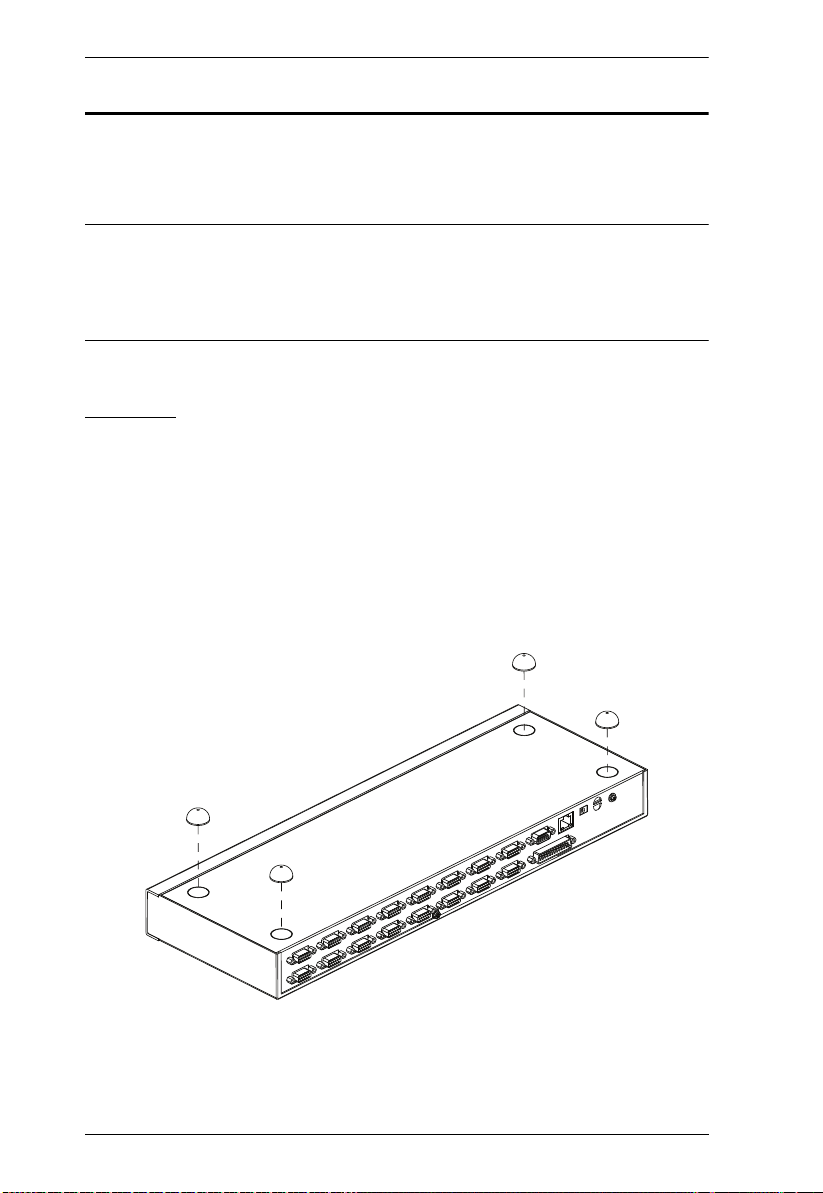
Stacking
The CS1708i / CS1716i can be placed on any level surface that can safely
support its weight and the weight of the attached cables. Make sure that the
surface is clean and free of any materials that can block the exhaust vents or
otherwise interfere with normal operation of the switch.
To place the CS1708i / CS1716i, or to stack units if you are daisy chaining
them, remove the backing material from the bottom of the rubber feet that came
with this package, and stick them onto the bottom panel at the corners, as
shown in the diagram, below:
12

2. Hardware Setup
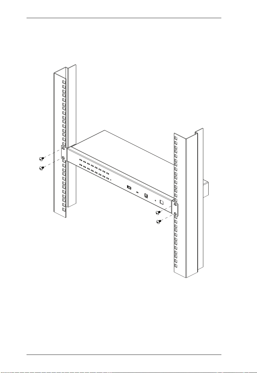
Rack Mounting – Front
1. Remove the screws from the left and right sides of the switch (2 screws
total) near the front of the switch.
2. Use the M3 x 8 Phillips hex head screws supplied with the rack mounting kit
to screw the rack mounting brackets into the sides near the front of the unit.
(Continues on next page.)
13
CS1708i / CS1716i User Manual
(Continued from previous page.)
3. Place the KVM switch in the rack. Position it so that the holes in the
mounting brackets line up with the holes in the rack. Secure the mounting
brackets to the front of the rack.
14

2. Hardware Setup
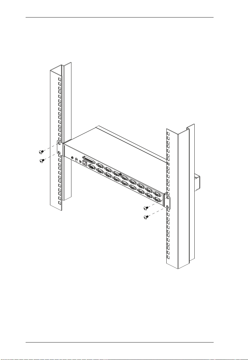
Rack Mounting – Rear
1. Remove 1 screw each from the left and right sides of the switch (2 screws
total) near the rear of the unit.
2. Use the M3 x 8 Phillips hex head screws supplied with the rack mounting kit
to screw the rack mounting brackets into the sides near the rear of the unit.
(Continues on next page.)
15
CS1708i / CS1716i User Manual
(Continued from previous page.)
3. Place the KVM switch in the rack. Position it so that the holes in the
mounting brackets line up with the holes in the rack. Secure the mounting
brackets to the rear of the rack.
16

2. Hardware Setup
Single Station Installation
To set up a single station installation refer to the diagram below (the numbers
in the diagram correspond with the numbers of the instruction steps), and do
the following:
1. Ground the CS1708i / CS1716i by connecting one end of the grounding
wire to the grounding terminal, and the other end of the wire to a suitable
grounded object.
2. Using the console cable provided with your switch, connect a USB or PS/2
keyboard, mouse, and monitor to the CS1708i / CS1716i console port.
(See Console Cable Installation Diagram on the following page.)
3. Use KVM cable sets (as described in the Cables section on page 6), to
connect any available KVM port to the keyboard, video and mouse ports
of the computer you are installing. (See KVM Cable Installation Diagrams
on the following page.)
4. Plug the power adapter cable into the CS1708i / CS1716i power jack, then
plug the power adapter into an AC power source.
After all the equipment has been connected up, power on the computers.
Note: Make sure the computers and devices that the CS1708i / CS1716i
connects to are also properly grounded.
17

CS1708i / CS1716i User Manual
2
3
4
1
Single Station Installation Diagram
18
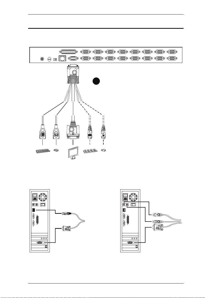
Cable Connection Diagrams
USB KVM Cable Connection PS/2 KVM Cable Connection
Console Cable Installation Diagram
2
USB PS/2
2. Hardware Setup
KVM Cable Installation Diagrams
19

CS1708i / CS1716i User Manual
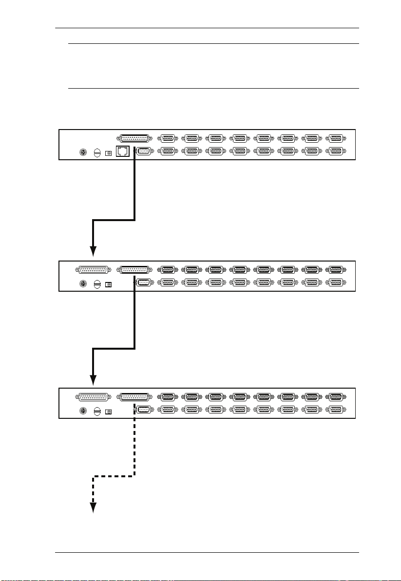
Daisy Chaining
To control even more computers, up to 15 additional switches can be daisy
chained down from the CS1708i / CS1716i. As many as 128 (CS1708i) or 256
(CS1716i) computers can be controlled from a single console in a complete
installation.
Note: 1. Tables showing the relation between the number of computers and the
number of CS1708i / CS1716i units needed to control them are
provided on page 190.
2. A list of supported KVM switches is provided on page 191.
To set up a daisy chained installation, refer to the installation diagram on the
following page, and do the following:
1. Make sure that all the switches you are adding to the chain are properly
grounded.
2. Use a daisy chain cable set (described in the Cables section, page 6), to
connect the Chain Out port of the CS1708i / CS1716i to the Chain In port
of the first chained unit.
3. To add additional switches to the chain, use daisy chain cable sets to
connect the Chain Out port of the parent switch to the Chain In port of the
child switch.
4. Connect the chained switches to their computers using appropriate KVM
cable sets (described in the Cables section, page 6), according to the
information given for single station installations.
Powering Up
After all the equipment has been connected up, power up the installation
according to the following procedure:
1. Plug in the power adapter for the CS1708i / CS1716i.
Wait for the unit’s station ID to display on the station ID LED.
The CS1708i / CS1716i is the first station. Its station ID is 01.
2. Plug in the power adapters for each station on the installation in turn
(second station, then third station, etc.).
3. In each case, wait for the station ID to be ascertained and displayed on the
current station before plugging in the next one.
4. After all the stations are up, power on the computers.
20
2. Hardware Setup
Note: Make sure the computers and devices that the CS1708i / CS1716i
connects to are also properly grounded.
Daisy Chain Installation Diagram
21

CS1708i / CS1716i User Manual
This Page Intentionally Left Blank
22

Chapter 3
Basic Operation
Port Selection
CS1708i / CS1716i installations provide three methods to obtain instant access
to any computer in your installation: Manual, OSD, and Hotkey.
Manual
For manual port selection, simply press the Port Selection Switch that
corresponds to the device you wish to access.
OSD/GUI
The CS1708i / CS1716i provides two menu driven interfaces to the port
selection procedure: A text-based OSD (On Screen Display), when you log in
from a local console; and a GUI (Graphical User Interface) when you log in
remotely over the Internet. Local console OSD operation is discussed in the
next chapter; GUI operations are discussed in Chapter 5 for Windows and Java
logins.
Keyboard Hotkeys
Hotkeys allow you to conveniently provide KVM focus to a particular
computer from the local console keyboard, instead of having to manually select
them by pressing Port Selection switches. See Hotkey Operation, page 40, for
details.
23

CS1708i / CS1716i User Manual
Hot Plugging
The CS1708i / CS1716i supports hot plugging – components can be removed
and added back into the installation by unplugging and replugging their cables
from the switch’s ports without the need to shut the unit down. In order for hot
plugging to work properly, however, the procedures described below must be
followed:
Hot Plugging Stations
You can change a station’s position by simply disconnecting it from its master
and reconnecting it to another switch in the chain. In order for the OSD menus
to correspond to the change, the station IDs must be reset in the OSD.
See RESET STATION IDS, page 35 for details.
Hot Plugging KVM Ports
After switching KVM ports, in order for the OSD menus to correspond to the
change, you must manually reconfigure the OSD information for the new Port
information. See F3: SET, page 32, and the Port Setting selections under the
F4 ADM function, page 34, for details.
Note: If the computer’s Operating System doesn’t support hot plugging, this
function may not work properly.
Hot Plugging Console Ports
The keyboard, monitor, and mouse can all be hot plugged. When hot plugging
the mouse:
You may unplug and replug the mouse (to reset the mouse)
Note: If, after hot plugging there is no response to keyboard and/or mouse
input, perform a Keyboard and Mouse Reset by simultaneously
pressing the 1 and 2 front panel port LEDs.
24

3. Basic Operation
Port ID Numbering
Each computer on a CS1708i / CS1716i installation is assigned a unique Port
ID. The Port ID is made up of two parts: a Station Number, and a Port Number:
The Station Number represents the position of the switch that the computer
is connected to in the daisy chain sequence.
The Port Number represents the position of the port that the computer is
connected to on the CS1708i / CS1716i station.
The station number precedes the port number.
Station and port numbers from 1–9 are padded with a preceding zero, so
they become 01–09.
For example, a computer attached to Port 6 of a station that was 12th in the
daisy chain sequence, would have a Station Number of 12 and a Port Number
of 06. It’s Port ID would be: 12-06.
Powering Off and Restarting
If it becomes necessary to power off a CS1708i / CS1716i, do the following
before restarting it:
1. Shut down all the computers that are attached to the CS1708i / CS1716i.
Note: Unplug the power cords of any computers that have the Keyboard
Power On function. Otherwise, the CS1708i / CS1716i will still
receive power from the computers.
2. Unplug the CS1708i / CS1716i from its power source.
3. Wait 10 seconds, then plug the CS1708i / CS1716i back in.
4. After the CS1708i / CS1716i has started and ascertained its station ID,
power on the computers.
Note: If you have shut down more than one station, power up the highest
station first and work your way down to the lowest one.
25

CS1708i / CS1716i User Manual
USB Peripheral Devices
The front panel USB port is available to connect a USB peripheral device (flash
drive, CD-ROM drive, printer, etc.) to the CS1708i / CS1716i. Any computer
connected to the CS1708i / CS1716i can access the USB peripheral on a oneat-a-time basis.
Note: Peripheral devices are only available to computers directly connected to
a CS1708i / CS1716i on the same level. They are not available to
computers connected to daisy chained switches.
USB peripherals are automatically detected on target computers when you
switch ports. For example, when you switch from to port 1 to port 2, the
peripheral automatically disconnects from the computer on port 1 and connects
to the computer on port 2.
26

Chapter 4
OSD Operation
Overview
When setting up your CS1708i / CS1716i installation for the first time, we
recommend doing it from the local console. OSD operation offers a menu
driven On Screen Display (OSD) to handle computer control and switching
operations.
All procedures start from the OSD Main Screen. To pop up the Main Screen,
tap [Scroll Lock] twice.
Note: [Scroll Lock] is the default OSD hotkey. You can optionally
change the Hotkey to the Ctrl key (see OSD HOTKEY, page 32).
Once you start the OSD, the keyboard lock will be controlled by
the device. When the OSD is being accessed, the number lock and
caps lock will always be on and usernames/passwords are not
case-sensitive.
The login screen appears:
Enter a valid Username and password to continue.
Note: The default username is administrator; the default password is
password. The first time you log in, you must use these defaults.
For security purposes, the default password must be changed
27

CS1708i / CS1716i User Manual
upon first login. To change the password, follow the browser
login procedure as instructed in Browser Login on page 50.
Usernames and passwords cannot be managed from the local
console. User management is handled via remote administration.
See User Management, page 107 for details.
Manufacturing Number
The “MFG Number” (Manufacturing Number) is an internal serial number
used by ATEN’s factory and technical support staff to identify products. This
number does not affect products’ warranty. If your product requires after-sales
services, you may provide the MFG Number to ATEN’s sales or technical
support staff to identify the product and model number.
OSD Main Screen
When you invoke the OSD, a screen similar to the one below appears:
The diagram depicts the administrator’s main screen. The user main screen
does not show the F4 and F6 functions, since these are reserved for the
administrator and can't be accessed by users.
The OSD always starts in LIST view, with the highlight bar at the same
position it was in the last time it was closed.
Only the ports that have been set accessible by the administrator for the
current logged in user are visible (see Port Access, page 87 for details).
The OSD uses a tree view. If a switch’s port list is collapsed, a plus symbol
displays in front of its Station Number. To see the ports click on the
switch’s Station Number, or move the highlight bar to it then press the
right arrow key. If you wish collapse a switch’s port list, click on the
switch’s Station Number, or move the highlight bar to it then press the left
arrow key.
28

4. OSD Operation
OSD Navigation
To dismiss the menu, and deactivate OSD, click the X at the upper right
corner of the OSD window; or press [Esc].
To log out, click F8 at the top of the main screen, or press [F8].
To move up or down through the list one line at a time, Click the Up and
Down Triangle symbols (ST) or use the Up and Down Arrow Keys. If
there are more list entries than there is room for on the Main Screen, the
screen will scroll.
To move up or down through the list one screen at a time, Click the Up and
Down Arrow symbols (), or use the [Pg Up] and [Pg Dn] keys. If there
are more list entries than there is room for on the Main Screen, the screen
will scroll.
To bring the KVM focus to a port, Double Click it, or move the Highlight
Bar to it then press [Enter].
After executing any action, you automatically go back to the menu one
level above.
OSD Main Screen Headings
SN--PN This column lists the Port ID numbers (Station Number - Port Number)
for all the KVM Ports on the installation. The simplest method to access
a particular computer is move the Highlight Bar to the port entry, then
press Enter.
QV If a port has selected for Quick View scanning (see SET QUICK VIEW
PORTS, page 35), an arrowhead displays in this column to indicate so.
The computers that are powered on and are online have a sun symbol
in this column to indicate so.
NAME If a port has been given a name (see EDIT PORT NAMES, page 34), its
name appears in this column.
29

CS1708i / CS1716i User Manual
OSD Functions
OSD functions are used to configure and control the OSD. For example, you
can rapidly switch to any port, scan selected ports, limit the list you wish to
view, designate a port as a quick view port, create or edit a port name, or make
OSD setting adjustments.
To access an OSD function:
1. Either Click a Function Key field at the top of the Main Screen, or press a
Function Key on the keyboard.
2. In the Submenus that appear make a choice by either double clicking it, or
by moving the Highlight Bar to it, and pressing [Enter].
3. Press [Esc] to return to the previous menu level.
F1: GOTO
GOTO allows you to switch directly to a port either by keying in the port's
Name, or its Port ID.
To use the name method, key in 1; key in the port's Name; then press
[Enter].
To use the Port ID method, key in 2; key in the Port ID; then press
[Enter].
Note: 1. You can key in a partial Name or Port ID. In that case, the screen will
show all the computers that the User has View rights to (see Access,
page 99), that match the Name or Port ID pattern, regardless of the
current List settings (see F2: LIST, page 31, for details).
2. Port access rights are assigned via the remote OSD. See User
Management, page 107 for details
To return to the OSD main screen without making a choice, press [Esc].
30

4. OSD Operation
F2: LIST
This function lets you broaden or narrow the scope of which ports the OSD
displays (lists) on the Main OSD Screen. Many of the OSD functions only
operate on the computers that are listed on the Main OSD Screen. The submenu
choices and their meanings are given in the table below.
Choice Meaning
ALL Lists all of the ports on the installation that have been set accessible
QUICK VIEW Lists only the ports that have been selected as Quick View Ports
POWERED ON Lists only the ports that have their attached computers powered on.
QUICK VIEW +
POWERED ON
Move the highlight bar to the choice you want, then press [Enter]. An icon
appears before the choice to indicate that it is the currently selected one.
by the administrator for the current logged in user.
(see SET QUICK VIEW PORTS, page 35).
Lists only the ports that have been selected as Quick View Ports
(see SET QUICK VIEW PORTS, page 35, and that have their
attached computers Powered On.
31

CS1708i / CS1716i User Manual
F3: SET
This function allows the administrator and each user to set up his own working
environment. A separate profile for each is stored by the OSD and is activated
according to the username that was provided during login.
To change a setting:
1. Double-click it; or move the highlight bar to it, then press [Enter].
2. After you select an item, a submenu with further choices appears. To make
a selection, either double-click it; or move the highlight bar to it, then
press [Enter]. An icon appears before the selected choice to indicate
which one it is. The settings are explained in the following table:
Setting Function
OSD HOTKEY Selects which hotkey activates the OSD function:
[Scroll Lock] [Scroll Lock] or [Ctrl] [Ctrl].
Since the [Ctrl] key combination may conflict with programs running
on the computers, the default is the [Scroll Lock] combination.
PORT ID
DISPLAY
POSITION
PORT ID
DISPLAY
DURATION
PORT ID
DISPLAY
MODE
SCAN
DURATION
Allows each user to customize the position where the Port ID
appears on the screen. The default is the upper left corner, but
users can choose to have it appear anywhere on the screen.
Use the mouse or the arrow keys plus Pg Up, Pg Dn, Home, End,
and 5 (on the numeric keypad with Num Lock off), to position the
Port ID display, then double-click or press [Enter] to lock the
position and return to the Set submenu.
Determines how long a Port ID displays on the monitor after a port
change has taken place. The choices are: 3 Seconds (default) and
Always Off.
Selects how the Port ID is displayed: the port number plus the port
name (PORT NUMBER + PORT NAME) (default); the port number
alone (PORT NUMBER); or the port name alone (PORT NAME).
Determines how long the focus dwells on each port as it cycles
through the selected ports in Auto Scan Mode (see F7: SCAN,
page 38). Key in a value from 0–255 seconds, then press [Enter].
Default is 5 seconds; a setting of 0 disables the Scan function.
32

4. OSD Operation
Setting Function
SCAN–SKIP
MODE
SCREEN
BLANKER
HOTKEY
COMMAND
MODE
HOTKEY This setting selects the Hotkey invocation keys (see Invoking
OSD
LANGUAGE
Selects which computers will be accessed under Skip Mode (see
F5: SKP, page 36), and Auto Scan Mode (see F7: SCAN, page 38).
Choices are:
ALL - All the Ports which have been set Accessible (
page 99),
POWERED ON - Only those Ports which have been set Accessible
and are Powered On;
QUICK VIEW - Only those Ports which have been set Accessible
and have been selected as Quick View Ports (see SET QUICK
VIEW PORTS, page 35);
QUICK VIEW + POWERED ON - Only those Ports which have
been set Accessible and have been selected as Quick View Ports
and are Powered On.
The default is ALL.
Note: The quick view choices only show up on the administrator's
screen, since only he has Quick View setting rights (see SET
QUICK VIEW PORTS, page 35, for details).
If there is no input from the console for the amount of time set with
this function, the screen is blanked. Key in a value from
0–30 minutes, then press [Enter]. A setting of 0 disables this
function. The default is 0 (disabled).
Enables / Disables the Hotkey Command function in case a conflict
with programs running on the computers occurs. The default is ON.
Hotkey Mode, page 41). Choices are:
[Num Lock] + [–] or [Ctrl] + [F12]
The default is [Num Lock] + [–].
Sets the language used in the OSD. Choices are: English (default),
German, Japanese, Simplified Chinese and Traditional Chinese.
see Access
,
33

CS1708i / CS1716i User Manual
F4: ADM
F4 is an administrator only function. It allows the administrator to configure
and control the overall operation of the OSD. To change a setting double-click
it, or use the up and down arrow keys to move the highlight bar to it then press
[Enter].
After you select an item, a submenu with further choices to select from appears.
Double-click an item, or move the highlight bar to it then press [Enter]. An
icon appears before the selected item so that you know which one it is. The
settings are explained in the following table:
Setting Function
SET IP
ADDRESS
SET LOGOUT
TIMEOUT
EDIT PORT
NAMES
This entry allows you to select whether to assign the CS1708i /
CS1716i’s IP address dynamically (DHCP), or to give it a fixed IP
address. Press [Space] to toggle between the choices.
If you toggle DHCP Enable to Off, specify the IP, Mask, and Gateway
in the appropriate fields. (Methods to determine the CS1708i /
CS1716i's IP address are described in the Appendix on page 178.)
Press [Esc] to exit after you have finished with your choice.
If there is no input from the console for the amount of time set with
this function, the Operator is automatically logged out. A login is
necessary before the console can be used again.
This enables other Operators to gain access to the computers when
the original Operator is no longer accessing them, but has forgotten
to log out. To set the timeout value, key in a number from 0–180
minutes, then press [Enter]. If the number is 0 (zero), this function is
disabled. Default is 0 (disabled).
To help remember which computer is attached to a particular port,
every port can be given a name. This function allows the
administrator to create, modify, or delete port names.
To edit a port name:
1. Click the port, or use the navigation keys to move the highlight
bar to it, then press [Enter].
2. Key in the new port name, or modify/delete the old one. The maximum number of characters allowed for the port name is 12.
Legal characters include:
All alpha characters: A–Z
All numeric characters: 0–9
- and Space
Case does not matter; OSD displays the port name in all capitals
no matter how they were keyed in.
3. When you have finished editing, press [Enter] to have the
change take effect. To abort the change, press [Esc].
34

Setting Function
RESTORE
DEFAULT
VAL UES
CLEAR THE
NAME LIST
ACTIVATE
BEEPER
SET QUICK
VIEW PORTS
RESET
STATION IDS
SET
OPERATING
SYSTEM
FIRMWARE
UPGRADE
This function is used to undo all changes and return the setup to the
original factory default settings (see Restoring Factory Default
Settings, page 192).
This function clears all the port names, and does not affect any other
settings.
Choices are Y (On), or N (Off). When activated, the beeper sounds
whenever a port is changed; when activating the Auto Scan function
(see F7: SCAN, page 38); or an invalid entry is made on an OSD
menu. The default is Y.
This function lets the administrator select which ports to include as
quick view ports.
To select/deselect a port as a Quick View Port, double-click the
port, or use the navigation keys to move the highlight bar to it,
then press [Spacebar].
When a port has been selected as a Quick View Port, an icon displays in the QV column of the port list on the Main Screen. When
a port is deselected, the icon disappears.
If one of the Quick View options is chosen for the LIST view (see
F2: LIST, page 31), only a port that has been selected here will
display on the list.
If one of the quick view options is chosen for Auto Scanning (see
SCAN–SKIP MODE, page 33), only a port that has been selected
here will be Auto Scanned.
The default has no ports selected for Quick View.
If you change the position of one of the Stations in the daisy chain,
the OSD settings will no longer correspond to the new situation. This
function directs the OSD to rescan the Station positions of the entire
installation and updates the OSD so that the OSD Station
information corresponds to the new physical layout.
Note: Only the Station Numbers get updated. Except for the Port
Names, all Administrator settings (such as Set Accessible Ports, Set
Quick View Ports, etc.), for all of the computers affected by the
change, have to be manually redone.
Specifies the operating platform of the computer attached to each
port. For each port, press [Space] to cycle through the choices (Win,
Mac1, Sun, and Mac2). Repeat until all the ports have been set, then
press [Esc]. The default is Win.
Note: If you are installing a Sun or Mac computer, before you run it
for the first time you must set the correct operating system for the
port it is connected to with this function; otherwise, it will not boot.
In order to upgrade the CS1708i / CS1716i firmware (see page 142),
you must first enable Firmware Upgrade mode with this setting.
When you bring up this menu, the current firmware version of the
KVM switch and the iCard will be displayed. Select Y to enable
Firmware Upgrade mode, or N to leave this menu without enabling it.
4. OSD Operation
35

CS1708i / CS1716i User Manual
Setting Function
KEYBOARD
LANGUAGE
Sets the keyboard mapping for the computer keyboard attached to
the KVM port. To select a keyboard language, double click it, or use
the navigation keys to move the highlight bar to it, then press
[Enter].
Choices are: AUTO (default), ENGLISH (US), ENGLISH (UK),
GERMAN (GER.), GERMAN (SWISS), FRENCH, HUNGARIAN,
ITALIAN, JAPANESE, KOREAN, RUSSIAN, SPANISH, SWEDISH
and TRADITIONAL CHINESE.
F5: SKP
This function enables you to easily skip backward or forward – switching the
console focus from the currently active KVM port to the previous or next
available one.
The selection of computers that are available for Skip Mode switching is made
with the Scan–Skip mode setting under the F3: SET function (see SCAN–SKIP
MODE, page 33). When you are in Skip Mode, press:
To skip from the current port to the previous port in the List.
To skip from the current port to the next port in the List.
To skip from the current port to the last port of the previous station
in the List.
To skip from the current port to the first port of the next station in
the List.
Note: When you skip, you only skip to the previous or next available
computer that is in the Scan–Skip Mode selection.
If a Port has been selected for Scan–Skip Mode, when the focus switches to
that port a Left/Right Triangle symbol appears before its Port ID Display
to indicate so.
While Skip Mode is in effect, the console will not function normally. You
must exit Skip Mode in order to regain control of the console.
To exit Skip Mode, press [Space] or [Esc].
36

4. OSD Operation
F6: BRC
F6 is an administrator only function. When Broadcast (BRC) mode is in effect,
commands sent from the console are broadcast to all available computers on
the installation.
This function is particularly useful for operations that need to be performed on
multiple computers, such as performing a system wide shutdown, installing or
upgrading software, etc.
While BRC mode is in effect, a speaker symbol appears before the Port ID
display of the port that currently has the console focus.
While BRC mode is in effect, the mouse will not function normally. You
must exit BRC mode in order to regain control of the mouse.
To exit BRC mode, invoke the OSD (with the OSD hotkey), then click the
F6 field, or press [F6], to turn BRC mode off.
37

CS1708i / CS1716i User Manual
F7: SCAN
This function (also referred to as Auto Scan Mode) allows you to automatically
switch the KVM focus among the available computers at regular intervals so
that you can monitor their activity without having to take the trouble of
switching manually.
The selection of computers to be included for auto scanning is made with
the Scan–Skip mode setting under the F3: SET function (see SCAN–SKIP
MODE, page 33).
The amount of time that each port displays for is set with the Scan
Duration setting under the F3: SET function (see SCAN DURATION,
page 32). When you want to stop at a particular location, press [Space] to
stop scanning and exit Auto Scan Mode.
If the scanning stops on an empty port, or one where the computer is
attached but is powered Off, the monitor screen will be blank, and the
mouse and keyboard will have no effect. Simply wait - after the Scan
Duration time is up, the Scan function will move on to the next port.
As each computer is accessed, an S appears in front of the Port ID display
to indicate that it is being accessed under Auto Scan Mode.
While Auto Scan Mode is in effect, the console will not function normally.
You must exit Auto Scan Mode in order to regain control of the console.
While you are in Auto Scan Mode, you can pause the scanning in order to
keep the focus on a particular computer by pressing P. See Auto Scan
Mode, page 43, for details.
To exit Auto Scan Mode, press the [Space] or [Esc].
38

4. OSD Operation
F8: LOUT
Clicking the F8 field, or pressing [F8] logs you out of OSD control of the
computers, and blanks the console screen. This is different from simply
pressing [Esc] when you are at the main screen to deactivate the OSD. With
this function you must log in all over again to regain access to the OSD,
whereas with [Esc], all you have to do to reenter the OSD is tap the OSD
hotkey.
Note: 1. When you reenter the OSD after logging out, the screen stays blank
except for the OSD login screen. You must input your username and
password before you can continue.
2. If you reenter the OSD after logging out, and immediately use [Esc]
to deactivate the OSD without having selected a port from the OSD
menu, a null port message displays on the screen. The OSD hotkey
will bring up the main OSD screen.
39

CS1708i / CS1716i User Manual
Hotkey Operation
Overview
In addition to the OSD, the CS1708i / CS1716i also supports port control and
configuration options directly from the keyboard with the use of hotkey
combinations.
Note: To use this function Hotkey Command Mode must be enabled.
See HOTKEY COMMAND MODE, page 33 for details
Hotkey port control allows you to provide KVM focus to a particular computer
directly from the keyboard. The CS1708i / CS1716i provides the following
Hotkey Port Control features:
Selecting the Active Port
Auto Scanning
Skip Mode Switching
The following hotkey configuration operations can also be performed:
Keyboard and Mouse Resets
Setting the Beeper
Toggling the Hotkey Invocation Keys
Toggling the OSD Hotkey
Setting the Port Operating System
Restoring the OSD Default Values
40

4. OSD Operation
Invoking Hotkey Mode
All Hotkey operations begin by invoking Hotkey Mode. Invoking Hotkey
Mode takes three steps:
1. Hold down the Num Lock key;
2. Press and release the minus key;
3. Release the Num Lock key:
[Num Lock] + [-];
Note: 1. The sequence uses the default hotkey invocation method. If you
selected the alternate hotkey invocation keys (see HOTKEY,
page 33), you would use [Ctrl] and [F12], instead.
2. The Minus (or F12) key must be released within one half second,
otherwise Hotkey invocation is automatically cancelled.
When Hotkey Mode is active:
The Caps Lock, and Scroll Lock LEDs flash in succession to indicate
Hotkey Mode is active. They stop flashing and revert to normal status
when you exit Hotkey Mode.
A Command Line appears on the monitor screen. The command line
prompt is the word Hotkey: in white text on a blue background, and
displays the subsequent Hotkey information that you key in.
Ordinary keyboard and mouse functions are suspended – only Hotkey
compliant keystrokes (described in the sections that follow), can be input.
Pressing [Esc] exits Hotkey Mode.
41

CS1708i / CS1716i User Manual
Hotkey Port Control
Selecting the Active Port
Each KVM port is assigned a Port ID (see Port ID Numbering, page 25). You
can directly access any computer on the installation with a Hotkey combination
that specifies the Port ID of the KVM port that the computer is connected to.
The steps involved are:
1. Invoke Hotkey Mode (see page 41).
2. Key in the Port ID
The Port ID numbers display on the Command Line as you key them in. If
you make a mistake, use [Backspace] to erase the wrong number.
Note: 1. Just key in the numbers; do not key in the dash.
2. If the port you want to switch to is on the current station, you can
just key in the port number – you do not need to key in the station
number.
3. Press [Enter]
After you press [Enter], the KVM focus switches to the designated
computer and you automatically exit Hotkey Mode.
Note: The KVM focus will not switch to a port if an invalid switch or port
number is entered. The command line will continue to display on the
screen until you enter a valid switch and port number combination,
or exit hotkey mode.
42

4. OSD Operation
Auto Scan Mode
Auto Scan Mode automatically switches among all the KVM ports that have
been set as accessible under Scan–Skip Mode at regular intervals, so that their
activity can be monitored automatically. (See SCAN–SKIP MODE, page 33.)
To start Auto Scan Mode, do the following:
1. Invoke Hotkey Mode (see page 41).
2. Press [A] [Enter].
After you press [A] [Enter], you automatically exit Hotkey Mode; enter
Auto Scan Mode; and Auto Scanning begins.
While you are in Auto Scan Mode, you can pause the scanning in order
to keep the focus on a particular computer by pressing P. During the
time that auto scanning is paused, the command line displays: Auto
Scan: Paused.
Pausing when you want to keep the focus on a particular computer is
more convenient than exiting Auto Scan Mode because when you
resume scanning, you start from where you left off. If, on the other
hand, you exited and restarted, scanning would start over from the very
first computer on the installation.
To resume auto scanning, press any key or right-click. Scanning
continues from where it left off.
While Auto Scan Mode is in effect, ordinary keyboard and mouse
functions are suspended – only Auto Scan Mode compliant keystrokes
and mouse clicks can be input. You must exit Auto Scan Mode in order
to regain normal control of the console.
3. To exit Auto Scan Mode press [Esc] or [Spacebar]. Auto scanning stops
when you exit Auto Scan Mode.
43

CS1708i / CS1716i User Manual
Skip Mode
This feature allows you to switch between computers in order to monitor them
manually. You can dwell on a particular port for as long as you like – as
opposed to auto scanning, which automatically switches after a fixed interval.
To invoke Skip Mode, do the following:
1. Invoke Hotkey Mode (see page 41).
2. Key in [Arrow]
Where [Arrow] refers to one of the Arrow keys. After you press
[Arrow], you automatically exit Hotkey Mode, and enter Skip Mode
where you can switch ports as follows:
Skips from the current port to the first accessible port previous to it.
(See SCAN–SKIP MODE, page 33, for information regarding
accessible ports.)
Skips from the current port to the next accessible port.
Skips from the current port to the last accessible port of the previous
station.
Skips from the current port to the first accessible port of the next
station.
Once you are in Skip Mode, you can keep on skipping by pressing the
Arrow keys. You don't have to use the hotkey invocation keys again.
While Skip Mode is in effect, ordinary keyboard and mouse functions
are suspended - only Skip Mode compliant keystrokes can be input.
You must exit Skip Mode in order to regain normal control of the
console.
3. To exit Skip Mode, press [Esc] or [Spacebar].
44

4. OSD Operation
Hotkey Configuration Operations
Keyboard / Mouse Reset
If the keyboard or mouse ceases to function on the computer connected to the
currently selected port, you can perform a keyboard / mouse reset on the
computer. This function is essentially the same as unplugging and replugging
the keyboard and mouse on the target computer. To perform a computer
keyboard / mouse reset, key in the following hotkey combination:
1. Invoke Hotkey Mode (see page 41).
2. Press [F5].
After you press [F5] you automatically exit Hotkey mode and regain keyboard
and mouse control on the computer connected to the KVM port. If you fail to
regain keyboard / mouse control on the computer after pressing [F5], perform
a console keyboard and mouse reset. For more information see Port Selection
Switches, page 8.
Hotkey Beeper Control
The Beeper (see ACTIVATE BEEPER, page 35) can be hotkey toggled On and
Off. When the beeper is set to On, the CS1708i / CS1716i beeps when it
switches ports. To toggle the Beeper, do the following:
1. Invoke Hotkey Mode (see page 41).
2. Press [B]
After you press B, the Beeper toggles On or Off. The Command Line displays
Beeper On or Beeper Off for one second; then the message disappears and you
automatically exit Hotkey Mode.
Toggling the Hotkey Invocation Keys
The Hotkey invocation keys (see HOTKEY, page 33) can be toggled between
the default set ([Num Lock] + [-]), and an alternate set ([Ctrl] + [F12]). To
toggle the invocation keys, do the following:
1. Invoke Hotkey Mode (see page 41).
2. Press [H].
After you press [H], the command line displays HOTKEY HAS BEEN
CHANGED for one second; then the message disappears and you
automatically exit Hotkey mode.
45

CS1708i / CS1716i User Manual
Toggling the OSD Hotkey
The OSD Hotkey (see OSD HOTKEY, page 32) can be toggled between [Scroll
Lock], [Scroll Lock] and [Ctrl], [Ctrl]. To toggle the OSD Hotkey, do the
following:
1. Invoke Hotkey Mode (see page 41).
2. Press [T].
After you press [T], the command line displays HOTKEY HAS BEEN
CHANGED for one second; then the message disappears and you
automatically exit Hotkey mode.
Set USB Speed
Users can use hotkeys to set the USB speed of the selected KVM port to low/
full speed to comply with the connected computers.
1. Invoke Hotkey mode (see Invoking Hotkey Mode on page 41).
2. Press [F11]
3. Key in [Function], where [Function] refers to one of the function keys in
the following table:
Key Description
L Set the KVM port to low speed USB
F Set the KVM port to full speed USB
4. Press [Enter].
To set all KVM ports of the selected KVM station, add an [A] after the function
key: Under Hotkey mode, press [F11][L][A][Enter] or [F11][F][A][Enter].
46

4. OSD Operation
Setting the Port Operating System
A KVM port’s operating system attribute can be set to match the OS used by
the computer attached to the port. To set a port’s operating system attribute, do
the following:
1. Invoke Hotkey Mode (see page 41).
2. Press a Function key according to the information shown in the following
table:
Key Description
F1 Sets the Port OS to Win (PC Compatible)
F2 Sets the Port OS to Mac
F3 Sets the Port OS to Sun
After pressing a function key you automatically exit Hotkey mode.
Restore Default Values
This administrator only hotkey restores the CS1708i / CS1716i default values
(see RESTORE DEFAULT VALUES, page 35). To restore the default values,
do the following:
1. Invoke Hotkey Mode (see page 41).
2. Press [R].
3. Press [Enter].
After you press [Enter], the command line displays RESET TO DEFAULT
SETTING for three seconds; then the message disappears and you
automatically exit Hotkey mode.
47

CS1708i / CS1716i User Manual
Hotkey Summary Table
The following table summarizes Hotkey operations on the CS1708i / CS1716i:
[Num Lock] + [-]
or
[Ctrl] + [F12]
[A] [Enter] Invokes Auto Scan mode.
When Auto Scan mode is in effect, [P]
pauses auto-scanning.
When auto-scanning is paused, pressing
any key or another right-click resumes autoscanning.
[B] Toggles the Beeper On or Off.
[Esc] or [Spacebar] Exits hotkey mode.
[F1] Set Operating System to Windows
[F2] Set Operating System to Mac
[F3] Set Operating System to Sun
[F5] Performs a keyboard / mouse reset on the
[H] Toggles the Hotkey invocation keys.
[Port ID] [Enter] Switches access to the computer that
[R] [Enter] Administrator only hotkey. It returns the
[F11] [F] [Enter] Set the selected KVM port to full speed
[F11] [L] [Enter] Set the selected KVM port to low speed
[F11] [F] [A] [Enter] Set the selected KVM station to full speed
[F11] [L] [A] [Enter] Set the selected KVM station to low speed
[T] Toggles the OSD Hotkey between [Ctrl]
[
]
]
[
[
]
]
[
target computer.
corresponds to that Port ID.
switch’s settings to their default values.
USB.
USB.
USB.
USB.
[Ctrl] and [Scroll Lock] [Scroll Lock].
Invokes Skip Mode and skips from the
current port to the first accessible port
previous to it.
Invokes Skip Mode and skips from the
current port to the next accessible port.
Invokes Skip Mode and skips from the
current port to the last accessible port of the
previous Station.
Invokes Skip Mode and skips from the
current port to the first accessible port of the
next Station.
48

Chapter 5
Logging In
Overview
The CS1708i / CS1716i can be accessed via its Graphical User Interface (GUI);
and remotely from an Internet browser; a Windows application (AP) program;
and a Java application (AP) program.
No matter which access method you choose, the CS1708i / CS1716i switch’s
authentication procedure requires you to submit a valid username and
password. If you supply invalid login information, the authentication routine
will return an Invalid Username or Password, or Login Failed message. If you
see this type of message, log in again with a correct username and password.
Note: If the number of invalid login attempts exceeds a specified amount, a
timeout period is invoked. You must wait until the timeout period
expires before you can attempt to log in again. See Login String,
page 130 for further details.
49

CS1708i / CS1716i User Manual
Browser Login
The CS1708i / CS1716i can be accessed via an Internet browser running on any
platform. To access the switch, do the following:
1. Open the browser and specify the IP address of the switch you want to
access in the browser's location bar.
Note: 1. For security purposes, a login string may have been set by the
administrator (see page 130 for details). If so, you must include a
forward slash and the login string along with the IP address when
you log in. For example:
192.168.0.100/cs1708i
2. If you don't know the IP address and login string, ask your
Administrator. The CS1708i / CS1716i’s default IP address is:
192.168.0.60
2. When a Security Alert dialog box appears, accept the certificate – it can be
trusted. (See Trusted Certificates, page 185, for details.) If a second
certificate appears, accept it as well.
Once you accept the certificate(s), the login page appears:
3. Provide your username and password (set by the administrator), then click
Login to bring up the Web Main Page. For a discussion of the Web Main
Page, see page 57.
Note: If you are the administrator and are logging in for the first time, use
the default username (administrator) and the default password
(password). For security purposes, the system will prompt you to
change the login password. The password must be different from
your default password.
50
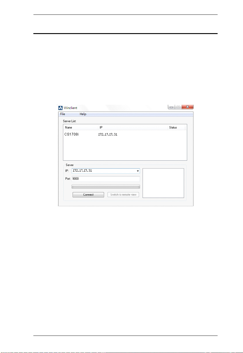
Chapter 5. Logging In
Windows Client AP Login
The Windows AP Client allows direct remote access to Windows systems
users, without having to go through a browser (although you initially download
the Windows AP Client program from the browser page – see Chapter 12,
Download). To connect to the CS1708i / CS1716i, go to the location on your
hard disk that you downloaded the Windows AP Client program to, and
double-click its icon (WinClient.exe).
To connect to the CS1708i / CS1716i, click the WinClient.exe program icon
(on your desktop) to bring up the Windows Client Connection screen:
51

CS1708i / CS1716i User Manual
The Windows Client AP Connection Screen
A description of the Connection Screen is given in the following table:
Item Description
Server List Each time the WinClient.exe file is run, it searches the user's
Server This area is used when you want to connect to a CS1708i /
Message List Panel Located just to the right of the Server panel, the Message List
Connect Click Connect after selecting a device in the Server list to
Switch to Remote View Once you have been authenticated (see Connecting –
local LAN segment for CS1708i / CS1716i, and lists
whichever ones it finds in this box. If you want to connect to
one of these units, double-click it. (See Connecting –
Windows Client AP, page 53 for details.)
Note: 1. The switch will not appear in the list unless its
CS1716i at a remote location. You can drop down the IP list
box and select an address from the list. If the address you
want isn't listed, you can key in the target IP address in the IP
field, and its port number in the Port field. (If you don't know
the port number, contact your Administrator.)
Panel lists status messages regarding the connection to the
CS1708i / CS1716i.
login with a secure connection.
Windows Client AP, page 53 for details), this button becomes
active. Click it to switch to the GUI Main Page. The GUI Main
Page is described on page 57.
Enable Device List configuration parameter has
been enabled.
2. Only units whose Access Port settings for Program
match the number specified for Port in the Server
area of this dialog box appear in the Server List
window.
When the IP address and Port number have been
specified, click Connect. (See Connecting – Windows
Client AP, page 53 for details.)
When you have finished with your session and come back
to this dialog box, click Disconnect to end the connection.
52
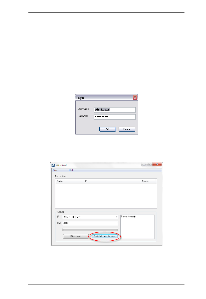
Chapter 5. Logging In
Connecting – Windows Client AP
To connect to a KVM over IP do the following::
1. From the Server List box, double-click the device that you wish to
connect to.
– Or –
Specify its IP address and port number in the Server IP and Port input
boxes.
2. Click Connect.
The Login dialog box appears:
3. Key in a valid Username and Password, and then click OK.
4. Once you have been authenticated, the Switch to remote view button
becomes active:
5. Click it to connect to the switch and bring up its GUI Main Page. For a
description of the GUI Main Page, see page 57.
53
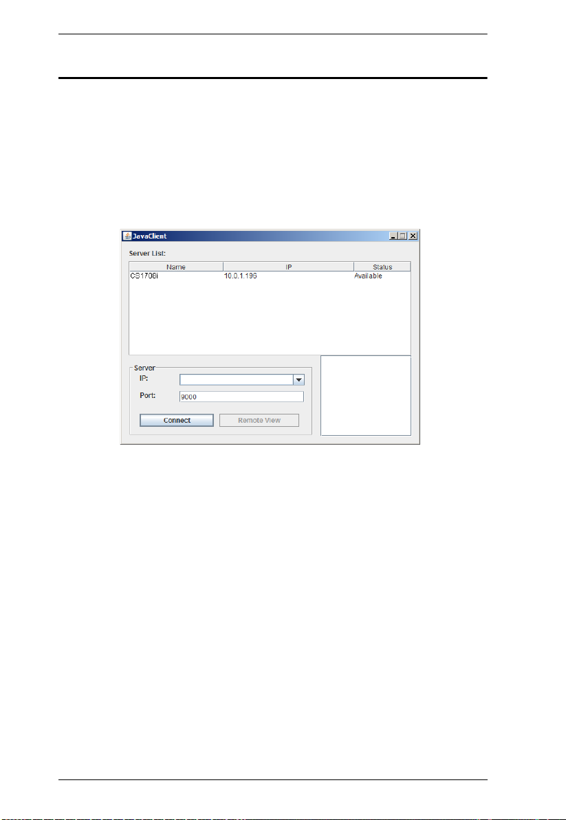
CS1708i / CS1716i User Manual
Java Client AP Login
The Java AP Client provides direct remote access to non-Windows systems
users (although you initially download the Java AP Client program from the
browser page – see Chapter 12, Download). To connect to the CS1708i /
CS1716i, go to the location on your hard disk that you downloaded the Java AP
Client program to, and double-click its icon (JavaClient.jar).
To connect to the CS1708i / CS1716i, click the JavaClient.jar program icon
(on your desktop) to bring up the Windows Client Connection screen:
54

Chapter 5. Logging In
The Java Client AP Connection Screen
A description of the Connection Screen is given in the following table:
Item Description
Server List Each time the JavaClient.jar file is run, it searches the User's
Server This area is used when you want to connect to a CS1708i /
Message List Panel Located just to the right of the Server panel, the Message List
Switch to Remote View Once you have been authenticated (see Connecting –
local LAN segment for CS1708i / CS1716i, and lists
whichever ones it finds in this box. If you want to connect to
one of these units, double-click it. (See Connecting –
Windows Client AP, page 53 for details.)
Note: 1. The switch will not appear in the list unless its
CS1716i at a remote location. You can drop down the IP list
box and select an address from the list. If the address you
want isn't listed, you can key in the target IP address in the IP
field, and its port number in the Port field. (If you don't know
the port number, contact your Administrator.)
Panel lists status messages regarding the connection to the
CS1708i / CS1716i.
Windows Client AP, page 53 for details), this button becomes
active. Click it to switch to the GUI Main Page. The GUI Main
Page is described on page 57.
Enable Device List configuration parameter has
been enabled.
2. Only units whose Access Port settings for Program
(see Service Ports, page 119) match the number
specified for Port in the Server area of this dialog
box appear in the Server List window.
When the IP address and Port number have been
specified, click Connect. (See Connecting – Windows
Client AP, page 53 for details.)
When you have finished with your session and come back
to this dialog box, click Disconnect to end the connection.
55
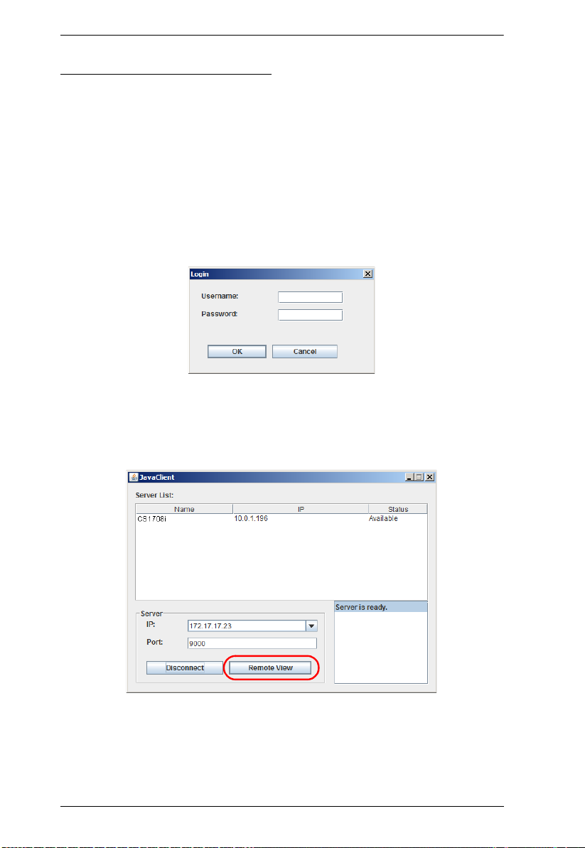
CS1708i / CS1716i User Manual
Connecting – Java Client AP
To connect to a KVM over IP do the following:
1. From the Server List box, double-click the device that you wish to
connect to.
– Or –
Specify its IP address and port number in the Server IP and Port input
boxes.
2. Click Login
The Login dialog box appears:
3. Key in a valid Username and Password, and then click OK.
4. Once you have been authenticated, the Remote View button becomes
active:
5. Click it to connect to the switch and bring up its GUI Main Page. For a
description of the GUI Main Page, see page 57.
56
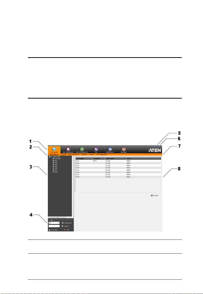
Chapter 6
The User Interface
Overview
Once you have successfully logged in, the CS1708i / CS1716i user interface
Main Page appears. The look of the page varies slightly, depending on which
method you used to log in. Each of the interfaces is described in the sections
that follow.
The Web Browser Main Page
To ensure multi-platform operability, access to the CS1708i / CS1716i can be
accomplished with most standard web browsers. Once users log in and are
authenticated (see page 49), the Web Browser Main Page comes up, with the
Port Access page displayed:
Note: The screen depicts an Administrator’s page. Depending on a user’s type
and permissions, not all of these elements appear.
57

CS1708i / CS1716i User Manual
Page Components
The web page screen components are described in the table, below:
No. Item Description
1 Tab Bar The tab bar contains the CS1708i / CS1716i main
2 Menu Bar The menu bar contains operational sub-categories
3 Sidebar The Sidebar provides a tree view listing of ports that
4 Filter The filter section at the bottom of the Sidebar lets you
Array Mode Clicking this icon opens a window in Array Mode
5 Help About provides information regarding the switch’s
6 Logout Click this button to log out of your CS1708i / CS1716i
7 Welcome Message If this function is enabled (see Welcome Message*,
8 Interactive Display Panel This is your main work area. The screens that appear
operation categories. The items that appear in the
tab bar are determined by the user’s type, and the
authorization options that were selected when the
user’s account was created.
that pertain to the item selected in the tab bar. The
items that appear in the menu bar are determined by
the user’s type, and the authorization options that
were selected when the user’s account was created.
relate to the various tab bar and menu bar selections.
Clicking a node in the Sidebar brings up a page with
the details that are relevant to it.
expand or narrow the scope of the ports that appear
in the Sidebar tree, as follows:
All – Lists all of the ports on the installation
Power On – Lists only the ports that have their
attached devices powered on
Search – Lists only the ports that relate to the text
typed in the search box. Enter text then click
Search.
(See Panel Array Mode, page 156).
current firmware version.
session.
page 97), a welcome message displays here.
reflect your menu choices and Sidebar node
selection.
58
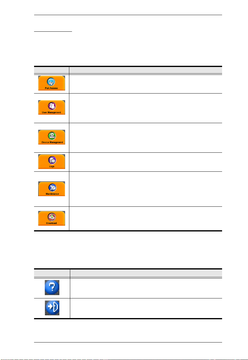
Chapter 6. The User Interface
The Tab Bar
The number and type of icons that appear on the Tab Bar at the top of the page
are determined by the user’s type (Administrator or User) and the permissions
assigned when the user’s account was created. The functions associated with
each of the icons are explained in the table below:
Icon Function
Port Access: The Port Access page is used to access and control the
devices on the CS1708i / CS1716i installation. This page is available to
all users.
User Management: The User Management page is used to create
and manage Users and Groups. It can also be used to assign devices
to them. User Management is discussed on page 107. This tab is
available to the Administrator, as well as users who have been given
User Management permission. The tab doesn’t appear for other users.
Device Management: The Device Management page is used to
configure and control the overall operation of the CS1708i / CS1716i.
This page is available to the Administrator, as well as users who have
been given Device Management permission. The tab doesn’t appear
for other and users.
Log: The Log page displays the contents of the log file. The Log page
is discussed on page 139.
Maintenance: The Maintenance page is used to install new firmware;
backup and restore configuration and account information; ping
network devices; and restore default values. The Maintenance page is
discussed on page 141. This page is available to the Administrator and
Users with Maintenance permission. The icon doesn’t display on the
page of ordinary users.
Download: Users can click this icon to download AP versions of the
Windows Client; the Java Client; and the Log Server. This page is
available to all users. The programs that can be downloaded depend
on the user’s permissions.
There are two small icons at the extreme right of the page. Their functions are
described in the table, below:
Icon Function
Click this icon to brings up a panel with information about the KVM
over IP switch firmware version.
Click this icon to log out and end your KVM over IP switch session.
59

CS1708i / CS1716i User Manual
The AP GUI Main Page
With WinClient AP, and Java Client AP access, once users log in (see Logging
In, page 49), the GUI Main Page comes up:
The GUI Main Page is similar to that of the Web Browser. The differences
between them are as follows:
1. The AP GUI version doesn’t have a menu bar below the tab bar; it has a
series of tabs like a notebook, instead. Like the Web Browser interface,
however, the makeup of the tabbed notebook changes depending on the
items selected on the main Tab Bar and in the Sidebar.
2. There is a hidden Control Panel at the upper or lower center of the screen
that becomes visible when you mouse over it. (The default is at the upper
center of the screen.)
60

Chapter 6. The User Interface
The Control Panel
WinClient Control Panel
Since the WinClient Control Panel contains the most complete functionality,
this section describes the WinClient Control Panel. Although the Java Control
Panel does not enable all of the features that this one does, the functions that
they do share are the same, and you can refer to the information described here
when using it.
The Control Panel is hidden at the upper or lower center of the screen (the
default is at the lower center), and becomes visible when you mouse over it.
The panel consists of three rows: an icon row at the top, and two text rows
below it:
Note: The above image shows the complete Control Panel. The icons that
appear can be user selected. See Control Panel Configuration, page 83,
for details.
By default, the upper text row shows the video resolution of the remote
display. As the mouse pointer moves over the icons in the icon bar,
however, the information in the upper text row changes to describe the
icon's function. In addition, if a message from another user is entered in
the message board, and you have not opened the message board in your
session, the message will appear in the upper row.
The lower row shows the IP address of the device you are accessing at the
left of the row.
61

CS1708i / CS1716i User Manual
Right clicking in the text row area brings up a menu-style version of the
toolbar. In addition, it allows you to select options for the Screen Mode,
Zoom, and Mouse Pointer type. These functions are discussed in the
sections that follow.
To move the Control Panel to a different location on the screen, place the
mouse pointer over the text row area, then click and drag.
62

Chapter 6. The User Interface
WinClient Control Panel Functions
The Control Panel functions are described in the table below.
Icon Function
This is a toggle. Click to make the Control Panel persistent – i.e., it
always displays on top of other screen elements. Click again to have
it display normally.
Click to bring up the Macros dialog box (see page 66 for details).
Click to bring up the Video Options dialog box. Right-click to perform
a quick Auto Sync (see Video Settings, page 73, for details).
Click to perform a video and mouse autosync operation. It is the
same as clicking the Auto-sync button in the Video Options dialog
box (see Video Settings, page 73).
Toggles the display between Full Screen Mode and Windowed Mode.
Click to take a snapshot (screen capture) of the remote display.
See Snapshot, page 84, for details on configuring the Snapshot
parameters.
Click to bring up the Message Board (see The Message Board,
page 76).
Click to send a Ctrl+Alt+Del signal to the remote system.
Click to toggle the remote display between color and gray scale
views.
Click to zoom the remote display window.
Note: This feature is only available in windowed mode (Full Screen
Mode is off). See Zoom, page 78 for details.
Click to bring up the on-screen keyboard (see The On-Screen
Keyboard, page 78).
Click to select the mouse pointer type.
Note: This icon changes depending on which mouse pointer type is
selected (see Mouse Pointer Type, page 80).
63

CS1708i / CS1716i User Manual
Click to toggle Automatic or Manual mouse sync.
When the selection is Automatic, a green appears on the icon.
When the selection is Manual, a red X appears on the icon.
See Mouse DynaSync Mode, page 81 for a complete explanation of
this feature.
Click to display a dropdown list of User macros in order to access
and run macros more conveniently than using the Macros dialog box
(see the Macros icon in the table above, and the Macros section on
page 66).
Under an accessed port, click to skip to the first port accessible to the
user on the entire installation without having to recall the Port Access
page.
Under an accessed port, click to skip to the first port accessible to the
user that is previous to the current one without having to recall the
Port Access page.
Under an accessed port, click to skip to the first port accessible to the
user that is after the current one without having to recall the Port
Access page.
Under an accessed port, click to skip to the last port accessible to the
user on the entire installation without having to recall the Port Access
page.
Under an accessed port, click to begin Auto Scan Mode. The KVM
over IP switch automatically switches among the ports that were
selected for Auto Scanning with the Filter function (see Filter,
page 90). This allows you to monitor their activity without having to
switch among them manually.
Under an accessed port, click to invoke Panel Array Mode
(See Panel Array Mode, page 156).
64
Under an accessed port, click to recall the GUI.
Click to bring up the Control Panel Configuration dialog box.
See Control Panel Configuration, page 83, for details on configuring
the Control Panel.
Click to exit the viewer.
Exiting from a Browser Viewer session brings you back to the web
browser Main Page.
Exiting from a WinClient AP session brings you back to the login
dialog box (see page 51).
Exiting from a Java Client AP session brings you back to the login
dialog box (see page 54).

Chapter 6. The User Interface
These icons show the Num Lock, Caps Lock, and Scroll Lock status
of the remote computer.
When the lock state is On, the LED is bright green and the lock
hasp is closed.
When the lock state is Off, the LED is dull green and the lock hasp
is open.
Click on the icon to toggle the status.
Note: These icons and your local keyboard icons are in sync.
Clicking an icon causes the corresponding LED on your keyboard to
change accordingly. Likewise, pressing a Lock key on your keyboard
causes the icon’s color to change accordingly.
65
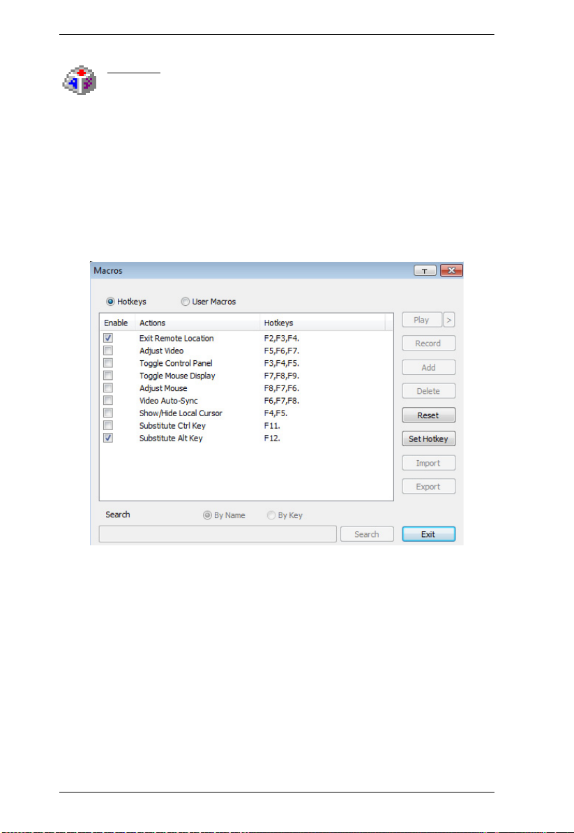
CS1708i / CS1716i User Manual
Macros
The Macros icon provides access to three functions found in the
Macros dialog box: Hotkeys, User Macros, and System Macros. Each
of these functions is described in the following sections.
Hotkeys
Various actions related to manipulating the remote server can be accomplished
with hotkeys. The Hotkey Setup utility (accessed by clicking this icon), lets you
configure which hotkeys perform the actions.
The hotkeys that invoke an action are shown to the right of its name. Use the
checkbox to the left of an action’s name to enable or disable its hotkey.
To change the hotkey for an action, do the following:
1. Highlight the Action, then click Set Hotkey.
2. Press your selected Function keys (one at a time). The key names appear in
the Hotkeys field as you press them.
You can use the same function keys for more than one action, as long
as the key sequence is not the same.
To cancel setting a hotkey value, click Cancel; to clear an action’s
Hotkeys field, click Clear.
3. When you have finished keying in your sequence, click Save.
To reset all the hotkeys to their default values, click Reset.
66

Chapter 6. The User Interface
An explanation of the Hotkey actions is given in the table below:
Action Explanation
Exit Remote
Location
Adjust Video Brings up the Video Settings dialog box. This is equivalent to
Toggle Control
Panel
Toggle Mouse
Display
Adjust Mouse This synchronizes the local and remote mouse movements. The
Video Autosync This combination performs an auto-sync operation. It is
Show/Hide Local
Cursor
Substitute Ctrl key If your local client computer captures Ctrl key combinations,
Substitute Alt key Although all other keyboard input is captured and sent to the
Breaks the connection to the CS1708i / CS1716i and returns you
to local client computer operation. This is equivalent to clicking
the Exit icon on the Control Panel. The default keys are F2, F3,
F4.
clicking the Video Settings icon on the Control Panel. The default
keys are F5, F6, F7.
Toggles the Control Panel On and Off. The default keys are F3,
F4, F5.
If you find the display of the two mouse pointers (local and
remote) to be confusing or annoying, you can use this function to
shrink the non-functioning pointer down to a barely noticeable tiny
circle, which can be ignored. Since this function is a toggle, use
the hotkeys again to bring the mouse display back to its original
configuration. This is equivalent to selecting the Single pointer
type from the Mouse Pointer icon on the Control Panel. The
default keys are F7, F8, F9.
Note: The Java Control Panel does not have this feature.
default keys are F6, F7, F8.
equivalent to clicking the Video Autosync icon on the Control
Panel. The default keys are F8, F7, F6.
Toggles the display of your local mouse pointer off and on. This is
equivalent to selecting the Null pointer type from the Mouse
Pointer icon on the Control Panel. The default keys are F4,F5.
preventing them from being sent to the remote server, you can
implement their effects on the remote server by specifying a
function key to substitute for the Ctrl key. If you substitute the F11
key, for example, pressing [F11 + 5] would appear to the remote
server as [Ctrl + 5]. The default key is F11.
CS1708i / CS1716i switch, [Alt + Tab] and [Ctrl + Alt + Del] work
on your local client computer. In order to implement their effects
on the remote server, another key may be substituted for the Alt
key. If you substitute the F12 key, for example, you would use
[F12 + Tab] and [Ctrl + F12 + Del]. The default key is F12.
67
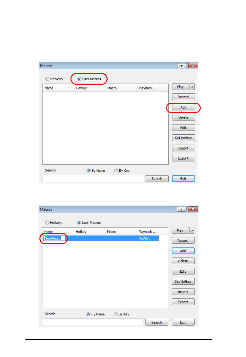
CS1708i / CS1716i User Manual
User Macros
User Macros are created to perform specific actions on the remote server. To
create the macro, do the following:
1. Select User Macros, then click Add.
2. In the dialog box that comes up, replace the “New Macro” text with a
name of your choice for the macro:
68
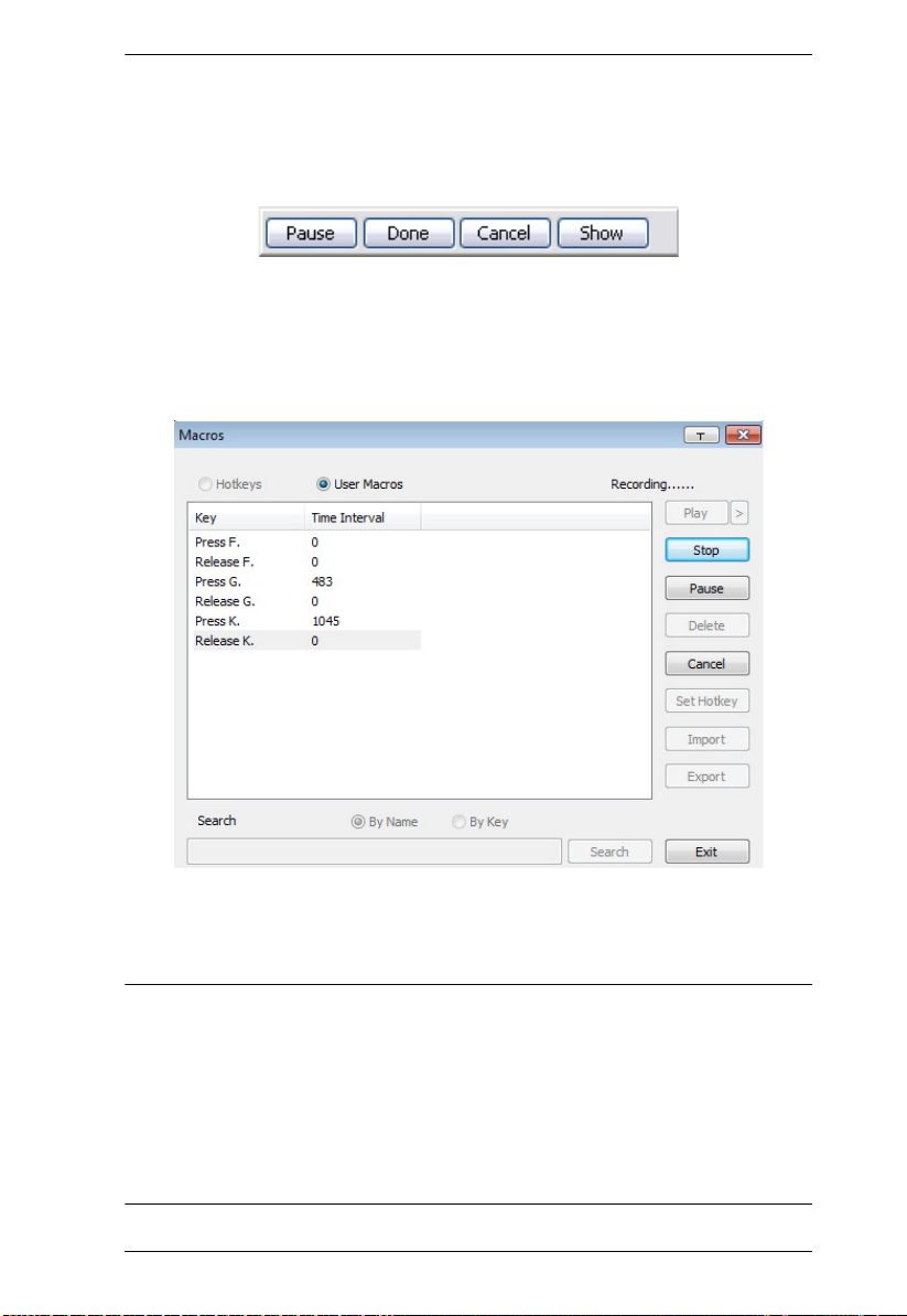
Chapter 6. The User Interface
3. Click Record.
The dialog box disappears, and a small panel appears at the top left of the
screen:
4. Press the keys for the macro.
To pause macro recording, click Pause. To resume, click Pause again.
Clicking Show brings up a dialog box that lists each keystroke that you
make, together with the amount of time each one takes:
Clicking Cancel cancels all keystrokes.
When you have finished, click Stop. (This is the equivalent of
clicking Done in Step 5.)
Note: 1. Case is not considered – typing A or a has the same effect.
2. When recording the macro the focus must be on the remote screen. It
cannot be in the macro dialog box.
3. Only the default keyboard characters may be used. Alternate
characters cannot be used. For example, if the keyboard is Traditional
Chinese and default character is A the alternate Chinese character
obtained via keyboard switching is not recorded.
69
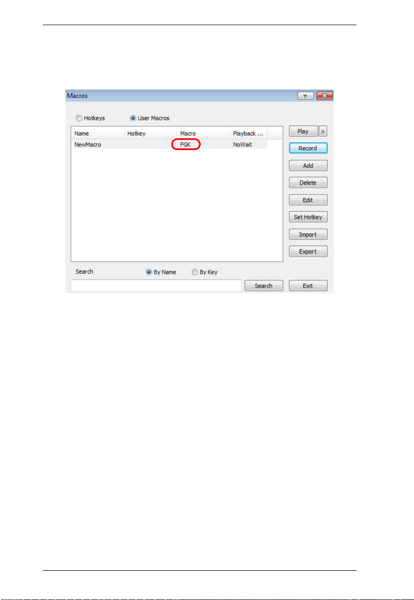
CS1708i / CS1716i User Manual
5. If you haven’t brought up the Show dialog, click Done when you have
finished recording your macro. You return to the Macros dialog box with
your macro key presses displayed in the Macro column:
6. If you want to change any of the keystrokes, select the macro and click
Edit. This brings up a dialog box similar to the one for Show. You can
change the content of your keystrokes, change their order, etc.
7. Repeat the procedure for any other macros you wish to create.
70
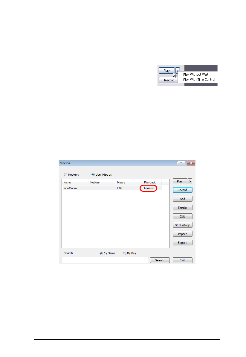
Chapter 6. The User Interface
After creating your macros, you can run them in any of three ways:
1. By using the hotkey (if one was assigned).
2. By opening the Macro List on the Control Panel and clicking the one you
want (see page 64).
3. By opening this (Macros) dialog box and
clicking Play.
If you run the macro from this dialog box, you
have the option of specifying how the macro runs.
If you choose Play Without Wait, the macro runs the keypresses one after
another with no time delay between them.
If you choose Play With Time Control, the macro waits for the amount of
time between key presses that you took when you created it. Click on the
arrow next to Play to make your choice.
If you click Play without opening the list, the macro runs with the default
choice (NoWait or TimeCtrl), which is shown in the Playback column.
You can change the default choice by clicking on the current choice
(NoWait in the screenshot above), and selecting the alternate choice.
Note: 1. Information about the Search function is given on page 72.
2. User Macros are stored on the Local Client computer of each user.
Therefore, there is no limitation on the of number of macros, the size
of the macro names, or makeup of the hotkey combinations that
invoke them
71

CS1708i / CS1716i User Manual
Search
Search, at the bottom of the dialog box, lets you filter the list of macros that
appear in the large upper panel for you to play or edit. Click a radio button to
choose whether you want to search by name or by key; key in a string for the
search; then click Search. All instances that match your search string appear in
the upper panel.
72
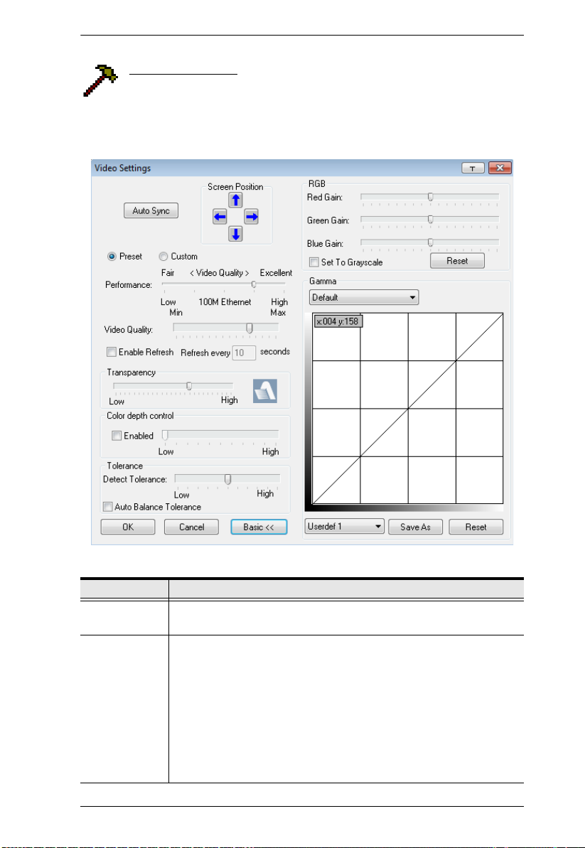
Chapter 6. The User Interface
Video Settings
Clicking the Hammer icon on the Control Panel brings up the Basic
Video Settings dialog box. The options in this dialog box allow you to
adjust the placement and picture quality of the remote screen on your monitor.
Click Advanced for more options.
The meanings of the video adjustment options are given in the table below:
Options Usage
Screen Position Adjust the horizontal and vertical position of the remote server
window by Clicking the Arrow buttons.
Auto-Sync Click Auto-Sync to have the vertical and horizontal offset values of
the remote screen detected and automatically synchronized with the
local screen.
Note: 1. If the local and remote mouse pointers are out of sync, in
most cases, performing this function will bring them back
into sync.
2. This function works best with a bright screen.
3. If you are not satisfied with the results, use the Screen
Position arrows to position the remote display manually.
73

CS1708i / CS1716i User Manual
Options Usage
RGB Drag the slider bars to adjust the RGB (Red, Green, Blue) values.
When an RGB value is increased, the RGB component of the image
is correspondingly increased.
If you enable Set to Grayscale, the remote video display is changed
to grayscale.
Gamma This section allows you to adjust the video display's gamma level.
This function is discussed in detail in the next section, Gamma
Adjustment.
Performance Select the type of Internet connection that the local client computer
uses. The switch will use that selection to automatically adjust the
Video Quality and Detect Tolerance settings to optimize the quality of
the video display.
Since network conditions vary, if none of the pre-set choices seem to
work well, you can select Advanced and use the Video Quality slider
bar to adjust the settings to suit your conditions.
Video Quality Drag the slider bar to adjust the overall Video Quality. The larger the
value, the clearer the picture and the more video data goes through
the network. Depending on the network bandwidth, a high value may
adversely effect response time.
Enable Refresh The CS1708i / CS1716i can redraw the screen every 1 to 99
seconds, eliminating unwanted artifacts from the screen. Select
Enable Refresh and enter a number from 1 through 99. The
CS1708i / CS1716i will redraw the screen at the interval you specify.
This feature is disabled by default. Click to put a check mark in the
box next to Enable Refresh to enable this feature.
Note: 1. The switch starts counting the time interval when mouse
movement stops.
2. Enabling this feature increases the volume of video data
transmitted over the network. The lower the number
specified, the more often the video data is transmitted.
Setting too low a value may adversely affect overall
operating responsiveness.
Transparency Adjusts the transparency of the toolbar that comes up when the GUI
hotkey ([Scroll Lock][Scroll Lock], for example), is invoked. Slide the
bar until the display in the example window is to your liking.
Color Depth
Control
This setting determines the richness of the video display by adjusting
the amount of color information.
Tolerance This setting also relates to video quality. It governs detecting or
ignoring pixel changes. A high setting can result in a lower quality
display due to less data transfer. A lower setting will result in better
video quality, but setting the threshold too low may allow too much
data to be transferred, negatively impacting network performance.
Check Auto Balance Tolerance to allow system managed settings.
Preset/Custom This setting allows you to set, save and revert to default settings.
74
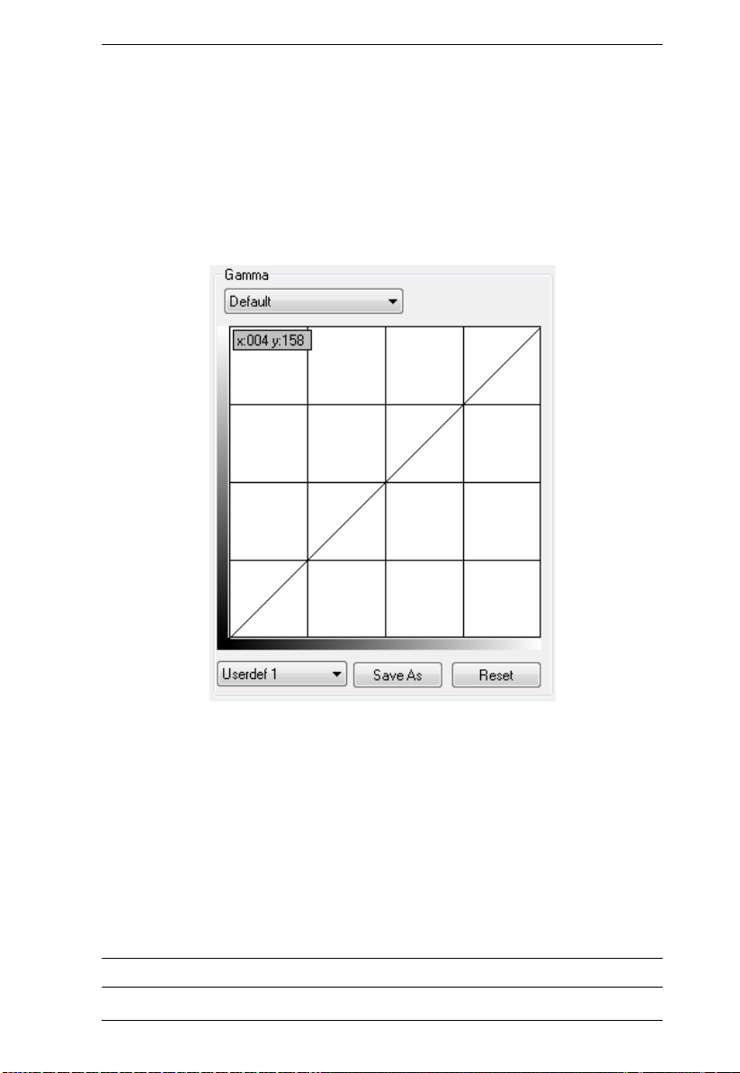
Chapter 6. The User Interface
Gamma Adjustment
If it is necessary to correct the gamma level for the remote video display, use
the Gamma function of the Video Adjustment dialog box.
Under Basic configuration, there are ten preset and four user-defined levels
to choose from. Drop down the list box and choose the most suitable one.
For greater control, clicking the Advanced button brings up the following
dialog box:
Click and drag the diagonal line at as many points as you wish to achieve
the display output you desire.
Click Save As to save up to four user-defined configurations derived from
this method. Saved configurations can be recalled from the list box at a
future time.
Click Reset to abandon any changes and return the gamma line to its
original diagonal position.
Click OK to save your changes and close the dialog box.
Click Cancel to abandon your changes and close the dialog box.
Note: For best results, change the gamma while viewing a remote server.
75

CS1708i / CS1716i User Manual
Network Bandwidth Information for KVM Sessions
For network bandwidth management, under ideal circumstances, a KVM
session of a full-screen video display at 1920x1080 @60Hz will take up
approximately 64Mbps.
However, since the network environment of each station/session varies, the
aforementioned information proposes what is ideal but does not warrant the
smoothness/quality for each session.
The Message Board
The CS1708i / CS1716i supports multiple user logins, which may
cause access conflicts. To alleviate the problem, a message board has
been provided, which allows users to communicate with each other:
Button Bar
The buttons on the Button Bar are toggles. Their actions are described in the
table below:
Button Action
Enable/Disable Chat. When disabled, messages posted to the board
are not displayed. The button is shadowed when Chat is disabled. The
icon displays next to the user's name in the User List panel when the user
has disabled Chat.
Occupy/Release Keyboard/Video/Mouse. When you Occupy the KVM,
other users cannot see the video, and cannot input keyboard or mouse
data. The button is shadowed when the KVM is occupied. The icon
displays next to the user's name in the User List panel when the user has
occupied the KVM.
76

Chapter 6. The User Interface
Occupy/Release Keyboard/Mouse. When you Occupy the KM, other
users can see the video, but cannot input keyboard or mouse data. The
button is shadowed when the KM is occupied. The icon displays next to
the user's name in the User List panel when the user has occupied the
KM.
Show/Hide User List. When you Hide the User List, the User List panel
closes. The button is shadowed when the User List is open.
Message Display Panel
Messages that users post to the board - as well as system messages - display in
this panel. If you disable Chat, however, messages that get posted to the board
won't appear.
Compose Panel
Key in the messages that you want to post to the board in this panel. Click
Send, or press [Enter] to post the message to the board.
User List Panel
The names of all the logged in users are listed in this panel.
Your name appears in blue; other users' names appear in black.
By default, messages are posted to all users. To post a message to one
individual user, select the user's name before sending your message.
If a user's name is selected, and you want to post a message to all users,
select All Users before sending your message.
If a user has disabled Chat, its icon displays before the user's name to
indicate so.
If a user has occupied the KVM or the KM, its icon displays before the
user's name to indicate so.
77

CS1708i / CS1716i User Manual
Zoom
The Zoom icon controls the zoom factor for the remote view window.
Settings are as follows:
Setting Description
100% Sizes and displays the remote view window at 100%.
75% Sizes and displays the remote view window at 75%.
50% Sizes and displays the remote view window at 50%.
25% Sizes and displays the remote view window at 25%.
1:1 Sizes and displays the remote view window at 100%. The difference
between this setting and the 100% setting is that when the remote
view window is resized its contents don’t resize – they remain at the
size they were. To see any objects that are outside of the viewing
area move the mouse to the window edge, to have the screen scroll.
The On-Screen Keyboard
The KVM over IP switch supports an on-screen keyboard, available in
multiple languages, with all the standard keys for each supported
language. Click this icon to pop up the on-screen keyboard:
One of the major advantages of the on-screen keyboard is that if the keyboard
languages of the remote and local systems aren’t the same, you don’t have to
change the configuration settings for either system. Just bring up the on-screen
keyboard; select the language used by the server you are accessing; and use the
on-screen keyboard to communicate with it.
Note: You must use your mouse to click on the keys. You cannot use your
actual keyboard.
Changing Languages
To change languages, do the following:
78

Chapter 6. The User Interface
1. Click the down arrow next to the currently selected language, to drop
down the language list.
2. Select the new language from the list.
Expanded Keyboard
To display/hide the expanded keyboard keys, click the arrow to the right of the
language list arrow.
79

CS1708i / CS1716i User Manual
Mouse Pointer Type
KVM over IP switches offer a number of mouse pointer options when
working in the remote display. Click this icon to select from the
available choices:
Note: 1. Before accessing a port, only Dual and Crosshairs are available for
the Windows Viewers. Once the port is accessed, all four pointers are
available.
2. The Dot pointer is not available with the Java Applet Viewer or the
Java Client AP.
3. Selecting the Dot pointer has the same effect as the Toggle mouse
display hotkey function (see Toggle Mouse Display, page 67 for
details).
4. The icon on the Control Panel changes to match your choice.
80

Chapter 6. The User Interface
Mouse DynaSync Mode
Synchronization of the local and remote mouse pointers is
accomplished either automatically or manually.
Automatic Mouse Synchronization (DynaSync)
Mouse DynaSync provides automatic locked-in synching of the remote and
local mouse pointers – eliminating the need to constantly resync the two
movements.
Note: This feature is only available for Windows and Mac systems (G4 or
later) whose adapter attribute OS setting is configured for Win or Mac.
All other configurations must use manual mouse synchronization
(described in the next section).
The icon on the Control Panel indicates the synchronization mode status as
follows:
Icon Function
This icon displays in gray to indicate that Mouse DynaSync is not
available – you must use manual synching procedures.
The green check mark on this icon indicates that Mouse DynaSync
is available and is enabled.
The red X on this icon indicates that Mouse DynaSync is available
but is not enabled.
When Mouse DynaSync is available, clicking the icon toggles its status
between enabled and /disabled. If you choose to disable Mouse DynaSync
mode, you must use the manual synching procedures described under Manual
Mouse Synchronization, page 82.
81
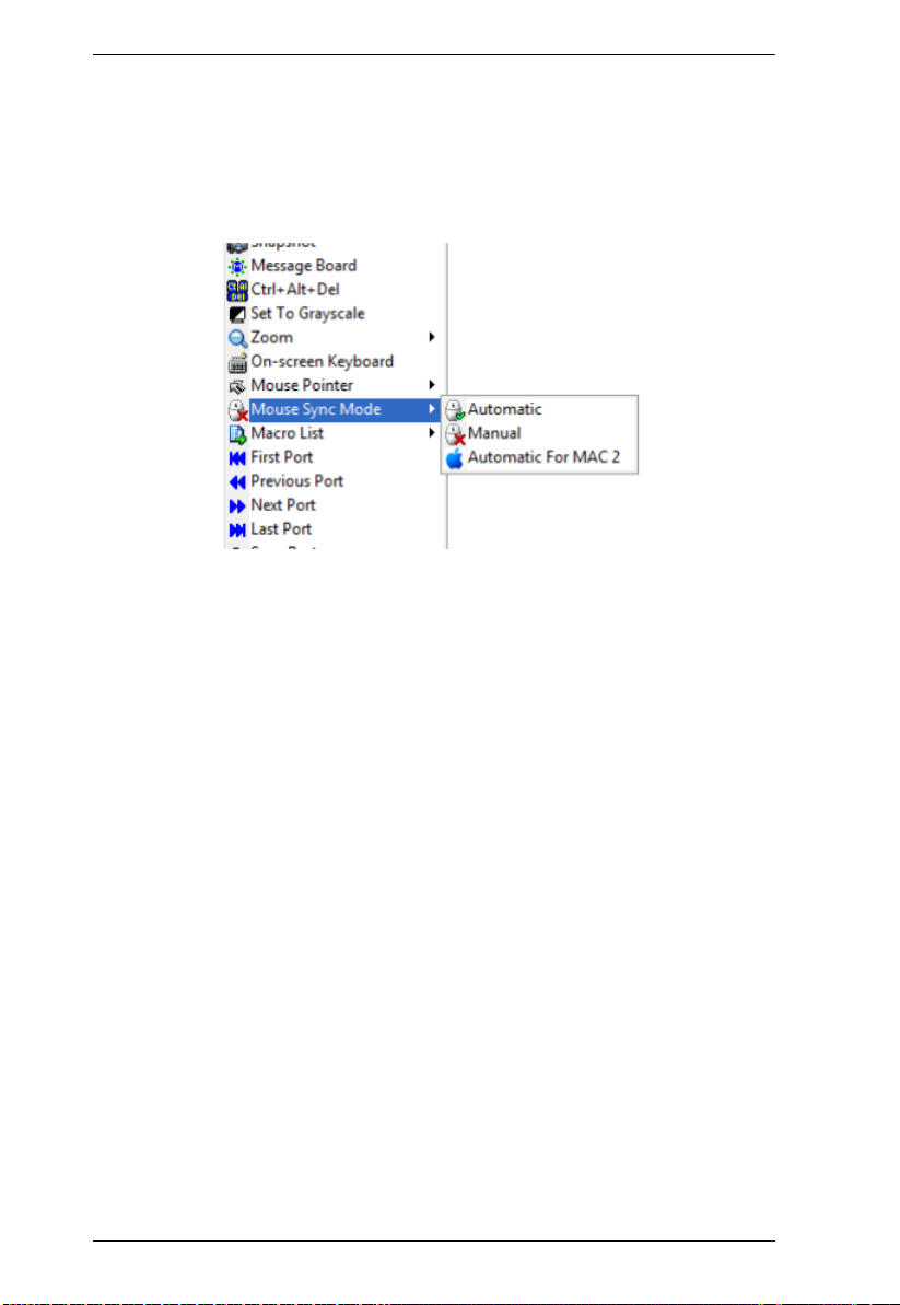
CS1708i / CS1716i User Manual
Mac and Linux Considerations
For Mac OS versions 10.4.11 or later, there is a second DynaSync setting
to choose from. If the default Mouse DynaSync result is not satisfactory,
try the Mac 2 setting. To select Mac 2, right click in the text area of the
Control Panel and select Mouse Sync Mode
Automatic for Mac 2:
Manual Mouse Synchronization
If the local mouse pointer goes out of sync with the remote system's mouse
pointer there are a number of methods to bring them back into sync:
1. Perform a video and mouse auto sync by clicking the Video Settings icon
on the Control Panel (see page 73).
2. Perform an Auto Sync with the Video Adjustment function (see Video
Settings, page 73, for details).
3. Invoke the Adjust Mouse function with the Adjust Mouse hotkeys (see
Adjust Mouse, page 67, for details).
4. Move the pointer into all 4 corners of the screen (in any order).
5. Drag the Control Panel to a different position on the screen.
6. Set the mouse speed and acceleration for each problematic server attached
to the switch. See Additional Mouse Synchronization Procedures,
page 183, for instructions.
82
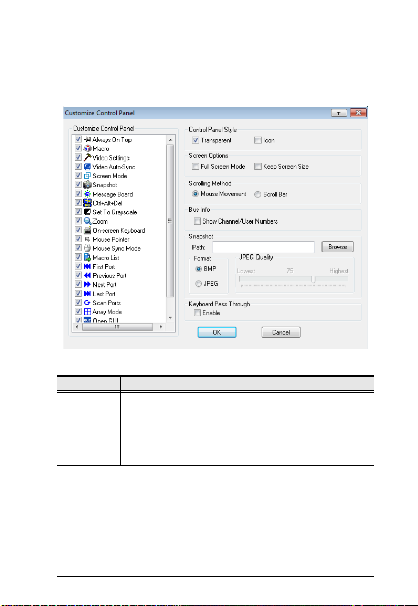
Chapter 6. The User Interface
Control Panel Configuration
Clicking the Control Panel icon brings up a dialog box that allows you to
configure the items that appear on the Control Panel, as well as its graphical
settings:
The organization of the dialog box is described in the table, below:
Item Description
Customize
Control Panel
Control Panel
Style
Allows you to select which icons display in the Control Panel. Check
the ones you want to see, uncheck the ones you don’t want.
Enabling Transparent makes the Control Panel semi-transparent,
so that you can see through it to the display underneath.
Enabling Icon causes the Control Panel to display as an icon until
you mouse over it, when the full panel then comes up.
83

CS1708i / CS1716i User Manual
Item Description
Screen Options
Scrolling
Method
Bus Info If bus Info is enabled, the number of the bus you are on, as well as
Snapshot These settings let the user configure the CS1708i / CS1716i’s screen
Keyboard Pass
Through
If Full Screen Mode is enabled, the remote display fills the entire
screen.
If Full Screen Mode is not enabled, the remote display appears as
a window on the local desktop. If the remote screen is larger than
what is able to fit in the window, move the mouse pointer to the
screen border that is closest to the area you want to view and the
screen will scroll.
If Keep Screen Size is enabled, the remote screen is not resized.
If the remote resolution is smaller than that of the local monitor,
its display appears like a window centered on the screen.
If the remote resolution is larger than that of the local monitor,
its display is centered on the screen. To access the areas that
are off screen, move the mouse to the corner of the screen that
is closest to the area you want to view and the screen will
scroll.
If Keep Screen Size is not enabled, the remote screen is resized to
fit the local monitor's resolution.
In cases where the remote screen display is larger than your monitor,
you can choose how to scroll to the areas that are off-screen.
If you select Mouse Movement, the screen will scroll when you
move the mouse pointer to your screen border.
If you select Scroll Bars, scroll bars appear around the screen
borders that you can use to scroll to the off-screen areas.
the total number of users on the bus, displays on the bottom row
center of the Control Panel as follows: Bus No./Total Users.
capture parameters (see the Snapshot description under The Control
Panel, page 61):
Path lets you select a directory that the captured screens
automatically get saved to. Click Browse; navigate to the directory
of your choice; then click OK. If you don’t specify a directory here,
the snapshot is saved to your desktop.
Click a radio button to choose whether you want the captured
screen to be saved as a BMP or a JPEG (JPG) file.
If you choose JPEG, you can select the quality of the captured file
with the slider bar. The higher the quality, the better looking the
image, but the larger the file size.
When this is enabled, the Alt-Tab key press is passed to the remote
server and affects that server. If it is not enabled, Alt-Tab acts on your
local client computer.
84
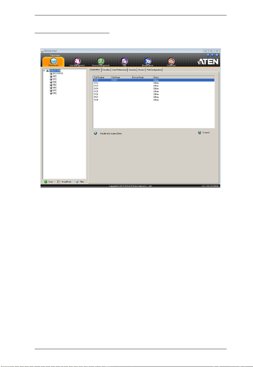
Chapter 6. The User Interface
The Java Control Panel
The Java Client AP Control Panel is similar to the one used by the WinClient:
The major differences between them are:
In the Macros dialog box, Toggle Mouse Display is not available.
The Dot mouse pointer type is not available.
In the Message Board, there is no Show/Hide button to show or hide the
user list. This function is achieved by clicking the arrows at the top of the
bar that separates the User List panel from the Main panel.
The Control Panel Lock LED icons are not in sync with your keyboard.
When you first connect, the LED display may not be accurate. To be sure,
click on the LED icons to set them.
In Control Panel Configuration, the BMP Snapshot format has been
replaced by PNG.
85

CS1708i / CS1716i User Manual
This Page Intentionally Left Blank
86
 Loading...