

Page 1

1-Local / Remote Share Access Single Port
ATEN Altusen™
CN9000 / CN9600 /
CN9950
1-Local/Remote Share Access
Single Port KVM over IP Switch
User Manual
KVM over IP Switch
CN9000 / CN9600 / CN9950
User Manual
www.aten.com
Page 2
CN9000 / CN9600 / CN9950 User Manual
EMC Information
FEDERAL COMMUNICATIONS COMMISSION INTERFERENCE
STATEMENT: This equipment has been tested and found to comply with the
limits for a Class A digital device, pursuant to Part 15 of the FCC Rules. These
limits are designed to provide reasonable protection against harmful
interference when the equipment is operated in a commercial environment.
This equipment generates, uses, and can radiate radio frequency energy and, if
not installed and used in accordance with the instruction manual, may cause
harmful interference to radio communications. Operation of this equipment in
a residential area is likely to cause harmful interference in which case the user
will be required to correct the interference at his own expense.
The device complies with Part 15 of the FCC Rules. Operation is subject to the
following two conditions: (1) this device may not cause harmful interference,
and (2) this device must accept any interference received, including
interference that may cause undesired operation.
FCC Caution: Any changes or modifications not expressly approved by the
party responsible for compliance could void the user's authority to operate this
equipment.
Warning: Operation of this equipment in a residential environment could
cause radio interference.
Achtung: Der Gebrauch dieses Geräts in Wohnumgebung kann
Funkstörungen verursachen.
KCC Statement
RoHS
This product is RoHS compliant.
Copyright © 2021 ATEN® International Co., Ltd.
ATEN and the ATEN logo are registered trademarks of ATEN International Co., Ltd. All rights reserved. All
other brand names and trademarks are the registered property of their respective owners.
ii
Released: 2021-03-23
Page 3

CN9000 / CN9600 / CN9950 User Manual
User Information
Online Registration
Be sure to register your product at our online support center:
International http://eservice.aten.com
Telephone Support
For telephone support, call this number:
International 886-2-8692-6959
China 86-400-810-0-810
Japan 81-3-5615-5811
Korea 82-2-467-6789
North America 1-888-999-ATEN ext 4988
1-949-428-1111
User Notice
All information, documentation, and specifications contained in this manual
are subject to change without prior notification by the manufacturer. The
manufacturer makes no representations or warranties, either expressed or
implied, with respect to the contents hereof and specifically disclaims any
warranties as to merchantability or fitness for any particular purpose. Any of
the manufacturer's software described in this manual is sold or licensed as is.
Should the programs prove defective following their purchase, the buyer (and
not the manufacturer, its distributor, or its dealer), assumes the entire cost of all
necessary servicing, repair and any incidental or consequential damages
resulting from any defect in the software.
The manufacturer of this system is not responsible for any radio and/or TV
interference caused by unauthorized modifications to this device. It is the
responsibility of the user to correct such interference.
The manufacturer is not responsible for any damage incurred in the operation
of this system if the correct operational voltage setting was not selected prior
to operation. PLEASE VERIFY THAT THE VOLTAGE SETTING IS
CORRECT BEFORE USE.
iii
Page 4

CN9000 / CN9600 / CN9950 User Manual
Package Contents
CN9000
1 CN9000 KVM over IP Switch
1 KVM cable (SPHD to VGA, PS/2, USB)
1 USB Type-A to USB Mini-B cable
1 power adapter
1 mounting kit
1 control terminal block
1 foot pad set (4 pcs)
1 user instructions*
CN9600
1 CN9600 KVM over IP Switch
1 KVM cable (DVI-D, USB, audio)
1 USB Type-A to USB Mini-B cable
1 power adapter
1 mounting kit
1 user instructions*
CN9950
1 CN9950 KVM over IP Switch
1 DisplayPort cable
1 USB Type-A to USB Type-B cable
1 USB Type-A to USB Mini-B cable
1 power adapter
1 mounting kit
1 control terminal block
1 foot pad set (4 pcs)
1 user instructions*
iv
Page 5

CN9000 / CN9600 / CN9950 User Manual
* Features may have been added to the CN9000 / CN9600 / CN9950 since this
manual was published. Please visit our website to download the most up-todate version.
Check to make sure that all components are present and in working condition.
If you encounter any problems, please contact your local dealer.
Read this manual thoroughly and follow the installation and operation
procedures to prevent any damage to the unit and/or any devices connected to
it.
Contents
EMC Information . . . . . . . . . . . . . . . . . . . . . . . . . . . . . . . . . . . . . . . . . . . . . ii
RoHS. . . . . . . . . . . . . . . . . . . . . . . . . . . . . . . . . . . . . . . . . . . . . . . . . . . . . . ii
User Information . . . . . . . . . . . . . . . . . . . . . . . . . . . . . . . . . . . . . . . . . . . . .iii
Online Registration . . . . . . . . . . . . . . . . . . . . . . . . . . . . . . . . . . . . . . . .iii
Telephone Support . . . . . . . . . . . . . . . . . . . . . . . . . . . . . . . . . . . . . . . .iii
User Notice . . . . . . . . . . . . . . . . . . . . . . . . . . . . . . . . . . . . . . . . . . . . . .iii
Package Contents. . . . . . . . . . . . . . . . . . . . . . . . . . . . . . . . . . . . . . . . . . . iv
Contents . . . . . . . . . . . . . . . . . . . . . . . . . . . . . . . . . . . . . . . . . . . . . . . . . . . v
About this Manual . . . . . . . . . . . . . . . . . . . . . . . . . . . . . . . . . . . . . . . . . . . xi
Conventions . . . . . . . . . . . . . . . . . . . . . . . . . . . . . . . . . . . . . . . . . . . . . . . xii
Product Information. . . . . . . . . . . . . . . . . . . . . . . . . . . . . . . . . . . . . . . . . . xii
1. Introduction
Overview . . . . . . . . . . . . . . . . . . . . . . . . . . . . . . . . . . . . . . . . . . . . . . . . . . .1
Features and Benefits. . . . . . . . . . . . . . . . . . . . . . . . . . . . . . . . . . . . . . . . .2
Hardware. . . . . . . . . . . . . . . . . . . . . . . . . . . . . . . . . . . . . . . . . . . . . . . . 2
Management . . . . . . . . . . . . . . . . . . . . . . . . . . . . . . . . . . . . . . . . . . . . .3
Easy-to-Use Interface . . . . . . . . . . . . . . . . . . . . . . . . . . . . . . . . . . . . . .4
Advanced Security . . . . . . . . . . . . . . . . . . . . . . . . . . . . . . . . . . . . . . . .4
Virtual Media . . . . . . . . . . . . . . . . . . . . . . . . . . . . . . . . . . . . . . . . . . . . .4
Virtual Remote Desktop . . . . . . . . . . . . . . . . . . . . . . . . . . . . . . . . . . . . 5
System Requirements. . . . . . . . . . . . . . . . . . . . . . . . . . . . . . . . . . . . . . . . .6
Remote User Computers. . . . . . . . . . . . . . . . . . . . . . . . . . . . . . . . . . . .6
Servers . . . . . . . . . . . . . . . . . . . . . . . . . . . . . . . . . . . . . . . . . . . . . . . . .6
Cables . . . . . . . . . . . . . . . . . . . . . . . . . . . . . . . . . . . . . . . . . . . . . . . . . . 7
Supported Video Resolutions . . . . . . . . . . . . . . . . . . . . . . . . . . . . . . . .8
Operating Systems . . . . . . . . . . . . . . . . . . . . . . . . . . . . . . . . . . . . . . . .8
Browsers . . . . . . . . . . . . . . . . . . . . . . . . . . . . . . . . . . . . . . . . . . . . . . . .9
v
Page 6

CN9000 / CN9600 / CN9950 User Manual
Components . . . . . . . . . . . . . . . . . . . . . . . . . . . . . . . . . . . . . . . . . . . . . . . 10
CN9000 Front View. . . . . . . . . . . . . . . . . . . . . . . . . . . . . . . . . . . . . . . 10
CN9000 Rear View . . . . . . . . . . . . . . . . . . . . . . . . . . . . . . . . . . . . . . . 11
CN9000/CN9950 Side View . . . . . . . . . . . . . . . . . . . . . . . . . . . . . . . . 12
CN9950 Front View. . . . . . . . . . . . . . . . . . . . . . . . . . . . . . . . . . . . . . . 13
9950 Rear View. . . . . . . . . . . . . . . . . . . . . . . . . . . . . . . . . . . . . . . . . . 14
CN9600 Front View. . . . . . . . . . . . . . . . . . . . . . . . . . . . . . . . . . . . . . . 15
CN9600 Rear View . . . . . . . . . . . . . . . . . . . . . . . . . . . . . . . . . . . . . . . 16
2. Hardware Setup
Mounting. . . . . . . . . . . . . . . . . . . . . . . . . . . . . . . . . . . . . . . . . . . . . . . . . . 17
Attaching the Bracket . . . . . . . . . . . . . . . . . . . . . . . . . . . . . . . . . . 17
Rack Mount . . . . . . . . . . . . . . . . . . . . . . . . . . . . . . . . . . . . . . . . . . 18
Wall Mount . . . . . . . . . . . . . . . . . . . . . . . . . . . . . . . . . . . . . . . . . . 19
Hardware Installation . . . . . . . . . . . . . . . . . . . . . . . . . . . . . . . . . . . . . . . . 20
CN9000. . . . . . . . . . . . . . . . . . . . . . . . . . . . . . . . . . . . . . . . . . . . . . . . 21
CN9600. . . . . . . . . . . . . . . . . . . . . . . . . . . . . . . . . . . . . . . . . . . . . . . . 22
CN9950. . . . . . . . . . . . . . . . . . . . . . . . . . . . . . . . . . . . . . . . . . . . . . . . . . . 23
DCE and DTE Ports . . . . . . . . . . . . . . . . . . . . . . . . . . . . . . . . . . . . . . . . . 24
3. Browser Login
Logging In. . . . . . . . . . . . . . . . . . . . . . . . . . . . . . . . . . . . . . . . . . . . . . . . . 25
Main Screen . . . . . . . . . . . . . . . . . . . . . . . . . . . . . . . . . . . . . . . . . . . . . . . 27
4. Configuration
Introduction. . . . . . . . . . . . . . . . . . . . . . . . . . . . . . . . . . . . . . . . . . . . . . . . 29
Basic Setting. . . . . . . . . . . . . . . . . . . . . . . . . . . . . . . . . . . . . . . . . . . . . . . 30
User Management. . . . . . . . . . . . . . . . . . . . . . . . . . . . . . . . . . . . . . . . 30
User Information . . . . . . . . . . . . . . . . . . . . . . . . . . . . . . . . . . . . . . 30
Role . . . . . . . . . . . . . . . . . . . . . . . . . . . . . . . . . . . . . . . . . . . . . . . . 30
Permissions. . . . . . . . . . . . . . . . . . . . . . . . . . . . . . . . . . . . . . . . . . 31
Account Policy. . . . . . . . . . . . . . . . . . . . . . . . . . . . . . . . . . . . . . . . . . . 32
Sessions . . . . . . . . . . . . . . . . . . . . . . . . . . . . . . . . . . . . . . . . . . . . . . . 33
Maintenance . . . . . . . . . . . . . . . . . . . . . . . . . . . . . . . . . . . . . . . . . . . . 34
Upgrade Main Firmware . . . . . . . . . . . . . . . . . . . . . . . . . . . . . . . . 34
Update Display Information. . . . . . . . . . . . . . . . . . . . . . . . . . . . . . 35
Backup / Restore. . . . . . . . . . . . . . . . . . . . . . . . . . . . . . . . . . . . . . 36
Terminal . . . . . . . . . . . . . . . . . . . . . . . . . . . . . . . . . . . . . . . . . . . . 38
Advanced Setting . . . . . . . . . . . . . . . . . . . . . . . . . . . . . . . . . . . . . . . . . . . 39
Device Information . . . . . . . . . . . . . . . . . . . . . . . . . . . . . . . . . . . . . . . 39
General . . . . . . . . . . . . . . . . . . . . . . . . . . . . . . . . . . . . . . . . . . . . . 39
Network. . . . . . . . . . . . . . . . . . . . . . . . . . . . . . . . . . . . . . . . . . . . . . . . 41
IP Installer . . . . . . . . . . . . . . . . . . . . . . . . . . . . . . . . . . . . . . . . . . . 42
Service Ports . . . . . . . . . . . . . . . . . . . . . . . . . . . . . . . . . . . . . . . . . 42
Redundant NIC . . . . . . . . . . . . . . . . . . . . . . . . . . . . . . . . . . . . . . . 43
vi
Page 7

CN9000 / CN9600 / CN9950 User Manual
IPv4 Settings . . . . . . . . . . . . . . . . . . . . . . . . . . . . . . . . . . . . . . . . . 43
IPv6 Settings . . . . . . . . . . . . . . . . . . . . . . . . . . . . . . . . . . . . . . . . . 44
Network Transfer Rate. . . . . . . . . . . . . . . . . . . . . . . . . . . . . . . . . .44
DDNS. . . . . . . . . . . . . . . . . . . . . . . . . . . . . . . . . . . . . . . . . . . . . . .44
ANMS . . . . . . . . . . . . . . . . . . . . . . . . . . . . . . . . . . . . . . . . . . . . . . . . .45
Event Destination. . . . . . . . . . . . . . . . . . . . . . . . . . . . . . . . . . . . . .45
SMTP Settings. . . . . . . . . . . . . . . . . . . . . . . . . . . . . . . . . . . . . . . .46
Authentication . . . . . . . . . . . . . . . . . . . . . . . . . . . . . . . . . . . . . . . .48
Security . . . . . . . . . . . . . . . . . . . . . . . . . . . . . . . . . . . . . . . . . . . . . . . .51
Login Failures . . . . . . . . . . . . . . . . . . . . . . . . . . . . . . . . . . . . . . . .51
Filter. . . . . . . . . . . . . . . . . . . . . . . . . . . . . . . . . . . . . . . . . . . . . . . .52
Encryption . . . . . . . . . . . . . . . . . . . . . . . . . . . . . . . . . . . . . . . . . . . 54
Security Level . . . . . . . . . . . . . . . . . . . . . . . . . . . . . . . . . . . . . . . .54
Mode . . . . . . . . . . . . . . . . . . . . . . . . . . . . . . . . . . . . . . . . . . . . . . .55
Private Certificate . . . . . . . . . . . . . . . . . . . . . . . . . . . . . . . . . . . . .55
Certificate Signing Request . . . . . . . . . . . . . . . . . . . . . . . . . . . . . . 57
Console Management . . . . . . . . . . . . . . . . . . . . . . . . . . . . . . . . . . . . .59
OOBC . . . . . . . . . . . . . . . . . . . . . . . . . . . . . . . . . . . . . . . . . . . . . . 59
Dial Out . . . . . . . . . . . . . . . . . . . . . . . . . . . . . . . . . . . . . . . . . . . . . 61
Serial Console . . . . . . . . . . . . . . . . . . . . . . . . . . . . . . . . . . . . . . . .63
Date/Time . . . . . . . . . . . . . . . . . . . . . . . . . . . . . . . . . . . . . . . . . . . . . . 66
Time Zone . . . . . . . . . . . . . . . . . . . . . . . . . . . . . . . . . . . . . . . . . . .66
Date / Time . . . . . . . . . . . . . . . . . . . . . . . . . . . . . . . . . . . . . . . . . .66
Network Time. . . . . . . . . . . . . . . . . . . . . . . . . . . . . . . . . . . . . . . . .67
Customization . . . . . . . . . . . . . . . . . . . . . . . . . . . . . . . . . . . . . . . . . . . 67
Mode . . . . . . . . . . . . . . . . . . . . . . . . . . . . . . . . . . . . . . . . . . . . . . .68
USB IO Settings. . . . . . . . . . . . . . . . . . . . . . . . . . . . . . . . . . . . . . .68
Multiuser Mode . . . . . . . . . . . . . . . . . . . . . . . . . . . . . . . . . . . . . . .68
Exit Macro . . . . . . . . . . . . . . . . . . . . . . . . . . . . . . . . . . . . . . . . . . . 69
Reset . . . . . . . . . . . . . . . . . . . . . . . . . . . . . . . . . . . . . . . . . . . . . . .69
Preferences. . . . . . . . . . . . . . . . . . . . . . . . . . . . . . . . . . . . . . . . . . . . . . . .70
User Preferences . . . . . . . . . . . . . . . . . . . . . . . . . . . . . . . . . . . . . . . .70
Logs. . . . . . . . . . . . . . . . . . . . . . . . . . . . . . . . . . . . . . . . . . . . . . . . . . .71
Remote Console . . . . . . . . . . . . . . . . . . . . . . . . . . . . . . . . . . . . . . . . .72
Remote Console Preview . . . . . . . . . . . . . . . . . . . . . . . . . . . . . . . 72
Telnet Viewer. . . . . . . . . . . . . . . . . . . . . . . . . . . . . . . . . . . . . . . . . 72
Download . . . . . . . . . . . . . . . . . . . . . . . . . . . . . . . . . . . . . . . . . . . . . .73
About. . . . . . . . . . . . . . . . . . . . . . . . . . . . . . . . . . . . . . . . . . . . . . . . . . . . .73
Viewer . . . . . . . . . . . . . . . . . . . . . . . . . . . . . . . . . . . . . . . . . . . . . . . . . . . .73
Logout . . . . . . . . . . . . . . . . . . . . . . . . . . . . . . . . . . . . . . . . . . . . . . . . . . . .74
5. Accessing Remote Server
Introduction . . . . . . . . . . . . . . . . . . . . . . . . . . . . . . . . . . . . . . . . . . . . . . . .75
Web, Windows and Java Client Viewer . . . . . . . . . . . . . . . . . . . . . . . . . .76
The Windows Client AP . . . . . . . . . . . . . . . . . . . . . . . . . . . . . . . . . . . . . .77
vii
Page 8

CN9000 / CN9600 / CN9950 User Manual
Download . . . . . . . . . . . . . . . . . . . . . . . . . . . . . . . . . . . . . . . . . . . . . . 77
Starting Up . . . . . . . . . . . . . . . . . . . . . . . . . . . . . . . . . . . . . . . . . . . . . 77
The Java Client AP. . . . . . . . . . . . . . . . . . . . . . . . . . . . . . . . . . . . . . . . . . 80
6. The Windows Client Viewer
The Win / Java Client Control Panel. . . . . . . . . . . . . . . . . . . . . . . . . . . . . 81
Control Panel Functions . . . . . . . . . . . . . . . . . . . . . . . . . . . . . . . . . . . 82
Macros . . . . . . . . . . . . . . . . . . . . . . . . . . . . . . . . . . . . . . . . . . . . . . . . 85
Hotkeys . . . . . . . . . . . . . . . . . . . . . . . . . . . . . . . . . . . . . . . . . . . . . 85
User Macros . . . . . . . . . . . . . . . . . . . . . . . . . . . . . . . . . . . . . . . . . 87
System Macros . . . . . . . . . . . . . . . . . . . . . . . . . . . . . . . . . . . . . . . 91
Video Settings. . . . . . . . . . . . . . . . . . . . . . . . . . . . . . . . . . . . . . . . . . . 93
Gamma Adjustment. . . . . . . . . . . . . . . . . . . . . . . . . . . . . . . . . . . . 94
The Message Board . . . . . . . . . . . . . . . . . . . . . . . . . . . . . . . . . . . . . . 96
The Button Bar . . . . . . . . . . . . . . . . . . . . . . . . . . . . . . . . . . . . . . . 96
Message Display Panel. . . . . . . . . . . . . . . . . . . . . . . . . . . . . . . . . 97
Compose Panel. . . . . . . . . . . . . . . . . . . . . . . . . . . . . . . . . . . . . . . 97
User List Panel . . . . . . . . . . . . . . . . . . . . . . . . . . . . . . . . . . . . . . . 97
Virtual Media . . . . . . . . . . . . . . . . . . . . . . . . . . . . . . . . . . . . . . . . . . . . 98
Virtual Media Icons . . . . . . . . . . . . . . . . . . . . . . . . . . . . . . . . . . . . 98
Virtual Media Redirection . . . . . . . . . . . . . . . . . . . . . . . . . . . . . . . 98
Smart Card Reader . . . . . . . . . . . . . . . . . . . . . . . . . . . . . . . . . . . 101
Zoom. . . . . . . . . . . . . . . . . . . . . . . . . . . . . . . . . . . . . . . . . . . . . . . . . 101
The On-Screen Keyboard. . . . . . . . . . . . . . . . . . . . . . . . . . . . . . . . . 102
Mouse Pointer Type . . . . . . . . . . . . . . . . . . . . . . . . . . . . . . . . . . . . . 103
Mouse DynaSync Mode . . . . . . . . . . . . . . . . . . . . . . . . . . . . . . . . . . 104
Automatic Mouse Synchronization (DynaSync) . . . . . . . . . . . . . 104
Manual Mouse Synchronization . . . . . . . . . . . . . . . . . . . . . . . . . 104
Mac and Linux Considerations . . . . . . . . . . . . . . . . . . . . . . . . . . 105
Open GUI (Configuration). . . . . . . . . . . . . . . . . . . . . . . . . . . . . . . . . 106
Control Panel Configuration . . . . . . . . . . . . . . . . . . . . . . . . . . . . . . . 107
The Web Client Control Panel . . . . . . . . . . . . . . . . . . . . . . . . . . . . . . . . 109
Web Client Video Settings . . . . . . . . . . . . . . . . . . . . . . . . . . . . . . . . 110
Web Client On-Screen Keyboard . . . . . . . . . . . . . . . . . . . . . . . . . . . 111
Web Client Mouse Pointer Type . . . . . . . . . . . . . . . . . . . . . . . . . . . . 111
Virtual Media . . . . . . . . . . . . . . . . . . . . . . . . . . . . . . . . . . . . . . . . . . . 112
Web Client Mouse Sync Mode . . . . . . . . . . . . . . . . . . . . . . . . . . . . . 113
7. Local Access
Local Console. . . . . . . . . . . . . . . . . . . . . . . . . . . . . . . . . . . . . . . . . . . . . 115
Local OSD. . . . . . . . . . . . . . . . . . . . . . . . . . . . . . . . . . . . . . . . . . . . . 117
Laptop USB Console (LUC) . . . . . . . . . . . . . . . . . . . . . . . . . . . . . . . . . . 118
8. The Log File
The Log File Screen . . . . . . . . . . . . . . . . . . . . . . . . . . . . . . . . . . . . . . . . 121
viii
Page 9

CN9000 / CN9600 / CN9950 User Manual
9. The Log Server
Installation. . . . . . . . . . . . . . . . . . . . . . . . . . . . . . . . . . . . . . . . . . . . . . . .123
Starting Up . . . . . . . . . . . . . . . . . . . . . . . . . . . . . . . . . . . . . . . . . . . . . . .123
The Menu Bar . . . . . . . . . . . . . . . . . . . . . . . . . . . . . . . . . . . . . . . . . . . . .124
Configure. . . . . . . . . . . . . . . . . . . . . . . . . . . . . . . . . . . . . . . . . . . . . . 125
Events . . . . . . . . . . . . . . . . . . . . . . . . . . . . . . . . . . . . . . . . . . . . . . . .126
Search . . . . . . . . . . . . . . . . . . . . . . . . . . . . . . . . . . . . . . . . . . . . .126
Maintenance . . . . . . . . . . . . . . . . . . . . . . . . . . . . . . . . . . . . . . . .127
Options . . . . . . . . . . . . . . . . . . . . . . . . . . . . . . . . . . . . . . . . . . . . . . .127
Help . . . . . . . . . . . . . . . . . . . . . . . . . . . . . . . . . . . . . . . . . . . . . . . . . .128
The Log Server Main Screen . . . . . . . . . . . . . . . . . . . . . . . . . . . . . . . . .128
Overview . . . . . . . . . . . . . . . . . . . . . . . . . . . . . . . . . . . . . . . . . . . . . .128
The List Panel . . . . . . . . . . . . . . . . . . . . . . . . . . . . . . . . . . . . . . . . . .129
Panel Showing Logs of the Selected Units . . . . . . . . . . . . . . . . . . . . 129
Appendix
Safety Instructions. . . . . . . . . . . . . . . . . . . . . . . . . . . . . . . . . . . . . . . . . .131
General . . . . . . . . . . . . . . . . . . . . . . . . . . . . . . . . . . . . . . . . . . . . . . .131
Rack Mounting . . . . . . . . . . . . . . . . . . . . . . . . . . . . . . . . . . . . . . . . .133
Technical Support . . . . . . . . . . . . . . . . . . . . . . . . . . . . . . . . . . . . . . . . . .134
International. . . . . . . . . . . . . . . . . . . . . . . . . . . . . . . . . . . . . . . . . . . .134
North America . . . . . . . . . . . . . . . . . . . . . . . . . . . . . . . . . . . . . . . . . .134
IP Address Determination. . . . . . . . . . . . . . . . . . . . . . . . . . . . . . . . . . . .135
IP Installer . . . . . . . . . . . . . . . . . . . . . . . . . . . . . . . . . . . . . . . . . . . . .135
Browser . . . . . . . . . . . . . . . . . . . . . . . . . . . . . . . . . . . . . . . . . . . . . . .136
AP Windows Client . . . . . . . . . . . . . . . . . . . . . . . . . . . . . . . . . . . . . .136
IPv6. . . . . . . . . . . . . . . . . . . . . . . . . . . . . . . . . . . . . . . . . . . . . . . . . . . . .138
Link Local IPv6 Address . . . . . . . . . . . . . . . . . . . . . . . . . . . . . . . . . . 138
IPv6 Stateless Autoconfiguration . . . . . . . . . . . . . . . . . . . . . . . . . . .139
Port Forwarding. . . . . . . . . . . . . . . . . . . . . . . . . . . . . . . . . . . . . . . . . . . . 140
Keyboard Emulation . . . . . . . . . . . . . . . . . . . . . . . . . . . . . . . . . . . . . . . .141
Serial Port Pin Assignment . . . . . . . . . . . . . . . . . . . . . . . . . . . . . . . . . . .142
Trusted Certificates. . . . . . . . . . . . . . . . . . . . . . . . . . . . . . . . . . . . . . . . .143
Overview . . . . . . . . . . . . . . . . . . . . . . . . . . . . . . . . . . . . . . . . . . . . . .143
Installing the Certificate. . . . . . . . . . . . . . . . . . . . . . . . . . . . . . . . . . .144
Certificate Trusted. . . . . . . . . . . . . . . . . . . . . . . . . . . . . . . . . . . . . . .145
Mismatch Considerations . . . . . . . . . . . . . . . . . . . . . . . . . . . . . . . . .145
Self-Signed Private Certificates . . . . . . . . . . . . . . . . . . . . . . . . . . . . . . .147
Examples. . . . . . . . . . . . . . . . . . . . . . . . . . . . . . . . . . . . . . . . . . . . . .147
Importing the Files. . . . . . . . . . . . . . . . . . . . . . . . . . . . . . . . . . . . . . .147
Troubleshooting . . . . . . . . . . . . . . . . . . . . . . . . . . . . . . . . . . . . . . . . . . .148
General Operation. . . . . . . . . . . . . . . . . . . . . . . . . . . . . . . . . . . . . . .148
Windows . . . . . . . . . . . . . . . . . . . . . . . . . . . . . . . . . . . . . . . . . . . . . .150
Java. . . . . . . . . . . . . . . . . . . . . . . . . . . . . . . . . . . . . . . . . . . . . . . . . .151
Sun Systems . . . . . . . . . . . . . . . . . . . . . . . . . . . . . . . . . . . . . . . . . . .152
ix
Page 10

CN9000 / CN9600 / CN9950 User Manual
Mac Systems. . . . . . . . . . . . . . . . . . . . . . . . . . . . . . . . . . . . . . . . . . . 153
The Log Server . . . . . . . . . . . . . . . . . . . . . . . . . . . . . . . . . . . . . . . . . 153
Additional Mouse Synchronization Procedures . . . . . . . . . . . . . . . . . . . 154
Windows:. . . . . . . . . . . . . . . . . . . . . . . . . . . . . . . . . . . . . . . . . . . . . . 154
Sun / Linux . . . . . . . . . . . . . . . . . . . . . . . . . . . . . . . . . . . . . . . . . . . . 155
Virtual Media Support . . . . . . . . . . . . . . . . . . . . . . . . . . . . . . . . . . . . . . . 156
WinClient ActiveX Viewer / WinClient AP . . . . . . . . . . . . . . . . . . . . . 156
Java Applet Viewer / Java Client AP. . . . . . . . . . . . . . . . . . . . . . . . . 156
Administrator Login Failure. . . . . . . . . . . . . . . . . . . . . . . . . . . . . . . . . . . 157
Specifications . . . . . . . . . . . . . . . . . . . . . . . . . . . . . . . . . . . . . . . . . . . . . 158
CN9000. . . . . . . . . . . . . . . . . . . . . . . . . . . . . . . . . . . . . . . . . . . . . . . 158
CN9600. . . . . . . . . . . . . . . . . . . . . . . . . . . . . . . . . . . . . . . . . . . . . . . 159
CN9950. . . . . . . . . . . . . . . . . . . . . . . . . . . . . . . . . . . . . . . . . . . . . . . 160
Limited Warranty. . . . . . . . . . . . . . . . . . . . . . . . . . . . . . . . . . . . . . . . . . . 162
x
Page 11

CN9000 / CN9600 / CN9950 User Manual
About this Manual
This User Manual is provided to help you get the most from your system. It
covers all aspects of installation, configuration and operation. An overview of
the information found in the manual is provided below.
Chapter 1, Introduction, introduces you to the CN9000 / CN9600 / CN9950
KVM over IP Switch. Its purpose, features and benefits are presented, and its
front and back panel components are described.
Chapter 2, Hardware Setup, describes how to set up your installation.
Diagrams showing the necessary steps are provided.
Chapter 3, Browser Login, describes how to log into the CN9000 /
CN9600 / CN9950 with a browser, and explains the functions of the icons and
buttons that appear on the opening page.
Chapter 4, Configuration, explains the administrative procedures that are
employed to configure the CN9000 / CN9600 / CN9950’s working
environment.
Chapter 5, Accessing Remote Server, describes how to access the
CN9000 / CN9600 / CN9950 remotely.
Chapter 6, The Windows Client Viewer, explains how to use the control
panel of the CN9000 / CN9600 / CN9950.
Chapter 7, Local Access, describes how to access the CN9000 / CN9600 /
CN9950 locally.
Chapter 8, The Log File, shows how to use the log file utility to view the
events that take place on the CN9000 / CN9600 / CN9950.
Chapter 9, The Log Server, explains how to install and configure the Log
Server.
Appendix, provides specifications and other technical information regarding
the CN9000 / CN9600 / CN9950.
xi
Page 12

CN9000 / CN9600 / CN9950 User Manual
Conventions
This manual uses the following conventions:
Monospaced Indicates text that you should key in.
[ ] Indicates keys you should press. For example, [Enter] means to
press the Enter key. If keys need to be chorded, they appear
together in the same bracket with a plus sign between them:
[Ctrl+Alt].
1. Numbered lists represent procedures with sequential steps.
♦ Bullet lists provide information, but do not involve sequential steps.
> Indicates consecutive selections, such as options on a menu or
dialog box. For example, Start
menu, and then select Run.
Indicates critical information.
Product Information
>
Run means to open the Start
For information about all ATEN products and how they can help you connect
without limits, visit ATEN on the Web or contact an ATEN Authorized
Reseller. Visit ATEN on the Web for a list of locations and telephone numbers:
International http://www.aten.com
North America http://www.aten-usa.com
xii
Page 13

Chapter 1
Introduction
Overview
The KVM over IP Switch (CN9000/CN9600/CN9950) is a cost-efficient overIP device that allows remote access and control to the video, audio, and virtual
media of a PC or workstation. It can also provide over-IP capability for
compatible ATEN KVM switches and/or LCD consoles, such as the CS1768
and/or CL3800.
The CN9000, CN9600, and CN9950 respectively supports one VGA, one DVI,
and one 4K DisplayPort video transmission, and is equipped with a FPGA
graphics processor that offers better image and video quality to enhance user
experience, while also offering RS-232 DTE/DCE standards of serial control
for its CPU COM and local console COM ports.
For user-friendly operation, an USB Mini-B port on the front panel is designed
as a laptop USB console (LUC) port. By simply connecting a laptop to the LUC
port, users can access any computer connected to the switch for easy on-site
management. That means no additional monitor, keyboard and mouse is
required for routine, local maintenance. Additionally, the CN9000/CN9600/
CN9950’s virtual media function allows users to perform diagnostic testing,
file transfers, or apply OS/application updates and patches from a remote
console.
To ensure seamless connectivity, the CN9000/CN9600/CN9950 is equipped
with dual LAN and dual power functionality to keep operation in the server
room smooth and efficient. The switch also supports microphone and speakers
on the local and remote console.
For ease of remote management, the CN9000/CN9600/CN9950 supports webfriendly KVM-over-IP access with its Web Client Viewer functionality, which
is compatible with major web browsers and runs directly off the browser
without Java or browser plug-in installations. Like its Java or Windows plugin counterparts, it allows users to remotely access the server / PC connected to
the device, but benefiting from a more direct and simple access option for
management and operation.
1
Page 14

CN9000/CN9600/CN9950 User Manual
Features and Benefits
Hardware
Compact and slim design for space usage optimization
Equipped with FPGA graphics processor for better image quality and
enhanced fps (frames per second) throughput for a crisp video display
response
Provides over-IP capability to KVM switches that do not have over-IP
functionality.
Local console provides USB keyboard and mouse support
A USB Mini-B port on the front panel serves as a laptop USB console
(LUC) port
Two 10/100/1000 Mbps NICs for redundant LAN or dual IP operation
Dual power supply for power backup
Supports multiplatform server environments: Windows, Mac, Sun, Linux
and VT100-based serial devices
Virtual media support
High video resolution — up to 1920 x 1200 @ 60Hz and 4096 x 2160 @
30Hz for both local and remote consoles for CN9000/CN9600 and
CN9950, respectively
Audio support — microphone and speakers are supported on the local and
remote console
Note: 1. For the list of compatible KVM switch models, please refer to the
Compatible Products section on the product web page.
2. Since there are a large number of keyboards/mouses with
functions specifically designed for OS other than Windows, they
may not be compatible and may have compatibility issue.
3. Some of the CN9000/CN9600/CN9950’s features may not be
supported, depending on the functionality of the cascaded KVM
switch. (For example, some switches do not support virtual
media.)
2
Page 15

Chapter 1. Introduction
Management
Complies to RS-232 DTE/DCE standards for serial control
Up to 64 user accounts — up to 32 users can simultaneously share control
Console access right management
End session feature — administrators can terminate running sessions
Event logging and Windows-based log server support
Event Logging — the device can record all events and write them to a
searchable database
Supports instant notification of critical system events via email, SNMP
trap and Syslog
Firmware upgradable via remote access
Accessible via a built-in serial viewer, or via third-party software (such as
PuTTY) for Telnet and SSH sessions
Out of Band support — accessible through its serial port using a dial-up
connection
Port Share Mode allows multiple users to gain access to a server
simultaneously
Local/Remote Share Mode conveniently grants shared or exclusive
console privileges
Integration with ATEN CC2000 Management Software (CN9600)
Integration with ATEN CCVSR Video Session Recording Software
(CN9600)
Supports ATEN KVM over IP Console Station (see Compatible Products
on the product web page)
DDNS — allows mapping of a dynamic IP address by assigning its
dynamic IP address, in a DHCP server, to a host name
Supports export/import of user accounts and configuration settings
Browser access permission — additional security feature to allow/disallow
browser/http/https access
Supports IPv6
3
Page 16

CN9000/CN9600/CN9950 User Manual
Easy-to-Use Interface
Browser-based GUIs offer a unified multilanguage interface to minimize
user training time and increase productivity
Multiplatform client support (Windows, Mac, Linux, Sun)
Multibrowser support (IE, Firefox, Safari, Opera, Chrome)
Browser-based UI in pure Web technology allows administrators to
perform administrative tasks without requiring pre-installed Java software
Supports web-friendly KVM-over-IP access with Web Client Viewer —
users can remotely access all the connected servers and PCs directly off
web-browsers without Java or browser plug-in installation
Full-screen or sizable and scalable virtual remote desktop
Magic Panel with configurable function for quick launch
Advanced Security
Smart card/CAC reader support
External authentication support: RADIUS, LDAP, LDAPS and MS Active
Directory
Supports TLS 1.2 data encryption and RSA 2048-bit certificates to secure
users logging in from browsers
Flexible encryption design allows users to choose any combination of 56-
bit DES, 168-bit 3DES, 256-bit AES, 128-bit RC4 or Random for
independent keyboard/mouse, video, and virtual media data encryption
Supports IP/MAC filter
Supports password protection
Private CA
Virtual Media
Virtual media enables file applications, OS patching, software installation
and diagnostic testing
Works with USB-enabled servers at OS and BIOS level
Supports USB 1.1 and USB 2.0 DVD/CD drives, USB mass storage
devices, PC hard drives, folders and ISO images
Virtual Remote Desktop
Video quality and video tolerance can be adjusted to optimize data transfer
speed; monochrome color depth, threshold and noise settings can be
4
Page 17

Chapter 1. Introduction
adjusted for compression of the data bandwidth in low bandwidth
situations
Full-screen video display or scalable video display
Message Board for communication among remote users
On-screen keyboard with multilanguage support
Mouse DynaSync
TM
— automatically synchronizes the local and remote
mouse movements
Supports exit macros
BIOS-level access
5
Page 18

CN9000/CN9600/CN9950 User Manual
System Requirements
Remote User Computers
Remote user computers (also referred to as client computers) are the ones the
users log into the switch with from remote locations over the Internet. The
following equipment must be installed on these computers:
The computers used to access the switch must have at least a P III 1 GHz
processor, with their screen resolution set to 1024 x 768. It is
recommended that your PC shall have P IV 2 GHz with at least 1 Gb of
RAM.
Browsers must support TLS 1.2 encryption.
A network transfer speed of at least 128 kbps is required.
For the Log Server, you must have the Microsoft Jet OLEDB 4.0 or higher
driver installed.
Servers
Servers are the computers connected to the switch via KVM cables. The
following equipment must be installed on these servers:
For USB KVM cable connections: a USB Type-A port and USB host
controller
For virtual media connection: an extra USB Type-A and USB host
controller
6
Page 19

Chapter 1. Introduction
Cables
A KVM cable set to link the CN9000/CN9600/CN9950 to a server or
KVM switch are provided with this package.
Custom KVM cable sets for CN9000/CN9600/CN9950 are available in
various lengths, as shown in the table below:
Model Cable Type Length CS Part Number
CN9000 PS/2-USB
VGA KVM
Cable
CN9600 USB DVI-D
Single Link
KVM Cable
CNCN9950 DisplayPort
Cable
To purchase additional cable sets, contact your dealer.
Cat 5e/6 or higher Ethernet cable(s) (not provided with this package),
should be used to connect the CN9000/CN9600/CN9950 to the LAN,
WAN, or Internet.
1.2 m 2L-5301UP
1.8 m 2L-5302UP
3.0 m 2L-5303UP
1.8 m 2L-7D02U
3.0 m 2L-7D03U
5.0 m 2L-7D05U
1.8 m 2L-7D02DP
3.0 m 2L-7D03DP
7
Page 20

CN9000/CN9600/CN9950 User Manual
Supported Video Resolutions
Resolutions
4096 x 2160 @ 30 Hz ●
3840 x 2160 @ 30 Hz ●
2560 x 2048 @ 30 Hz ●
2560 x 1600 @ 30 Hz ●
2560 x 1440 @ 30 Hz ●
1920 x 1200 @ 60 Hz ●●
1920 x 1080 @ 60 Hz ●●
1680 x 1050 @ 60 Hz ●●
1600 x 1200 @ 60 Hz ●●
1600 x 900 @ 60 Hz ●●
1440 x 900 @ 60 Hz ●●
1400 x 1050 @ 60 Hz ●●
1360 x 768 @ 60 Hz ●
1280 x 1024 @ 60 Hz ●●
1280 x 1024 @ 75 Hz ●
1280 x 960 @ 60 Hz ●●
1280 x 720 @ 60 Hz ●●
1152 x 864 @ 75 Hz ●
1024 x 768 @ 60/70 Hz ●●
1024 x 768 @ 75/85 Hz ●
800 x 600 @ 56/60 Hz ●●
800 x 600 @ 72/75/85 Hz ●
720 x 400 @ 70 Hz ●●
640 x 480 @ 60 Hz ●●
640 x 480 @ 72/75/85 Hz ●
CN9000/CN9600 CN9950
Operating Systems
Supported operating systems for remote user computers that log into the
CN9000/CN9600/CN9950 include Windows 2000 or above, and other
systems capable of running Sun's Java Runtime Environment (JRE) 6,
Update 3, or later (Linux, Mac, Sun, etc.).
Supported operating systems for servers that connect to the CN9000/
CN9600/CN9950 are shown in the table below:
OS Version
Windows 2000 or above
8
Page 21

Chapter 1. Introduction
OS Version
Linux RedHat 9.0,Fedora or later
RHEL AS 4, RHEL 5
SUSE 10/ 11.1 or later
Debian 3.1/ 4.0or later
Ubuntu 7.04 / 7.10 or later
UNIX IBM AIX 5L / V6 or later
FreeBSD 5.5/ 6.1 / 6.2 or later
Sun Solaris 8/ 9 / 10 or later
Mac OS 10.1 or later
Note: For Linux systems, Linux Kernel must be 2.6 or later to support USB
2.0.
Browsers
Note:Supported browsers for users that log into the CN9000/CN9600/CN9950
include the following:See Mac Systems, page 153, for further information
Browser Version
Internet Explorer 8 or later
Chrome 4.0.3 or later
Firefox 3.5.3 or later
Safari 4.0.3 or later
Opera 10.10 or later
regarding Safari.
9
Page 22
CN9000/CN9600/CN9950 User Manual
2 3 4 5 6 7 8
Components
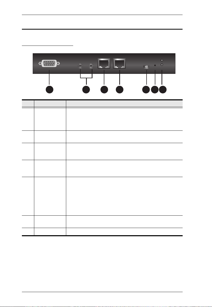
CN9000 Front View
No. Component Description
1 PC/KVM SPHD
port
2 KVM audio
ports
3CPU COM
(RS-232 DTE)
port
4 local console
COM (RS-232
DCE) port
5 laptop USB
console (LUC)
port
6 reset button Press the reset button for more than 3 seconds to revert the
7 power LED Lights Green when the CN9000 is powered up.
Use the KVM cable provided to connect the PC / server or
KVM switch to the CN9000 through this port.
Note: For keyboard and mouse signal transmission, users can
choose between PS/2 or USB connections.
Connect the audio of the PC / server to this port for audio
signal transmission.
Connect a serial data communication equipment device (e.g. a
modem or PC) to this port. See page 24 for details.
Connect a serial data terminal equipment device (e.g. a PC or
touch panel) to this port. See page 24 for details.
For laptop local access (See Local Access, page 115),
connect the laptop to this port using the USB Type-A to USB
Mini-B cable provided.
Make sure the mode of USB IO Settings (see USB IO
Settings, page 68) is set to LUC.
If the mode of USB IO Settings is set to Virtual Media, this port
will not work.
unit back to factory default settings.
10
Page 23

Chapter 1. Introduction
2 3 4 5 6
CN9000 Rear View
No. Component Description
1 grounding terminal Connect to a suitable grounding object.
2 power jacks Plug the power adapter provided into an AC power
3 control terminal
4 LAN ports Connect a Cat 5e/6 network cable to these ports for
5 local console ports Connect the cables for the local console (USB
source, then plug the power adapter cable into one of
the power jacks.
Plug a second power adapter into another AC power
source, then plug the power cable into the other
CN9000 power jack.
Note: Dual power operation is optional — the second
power source is for backup; a second power adapter
requires a separate purchase.
Connect the NC and C terminals to the PC / server
for remote reboot.
Connect the GND and DI terminals to an input
device (e.g. thermometer, humidity sensor) for digital input notification.
uplink connection.
keyboard, VGA monitor, USB mouse, microphone and
speakers) to these ports. Each connector is color
coded and marked with an icon.
11
Page 24
CN9000/CN9600/CN9950 User Manual
2
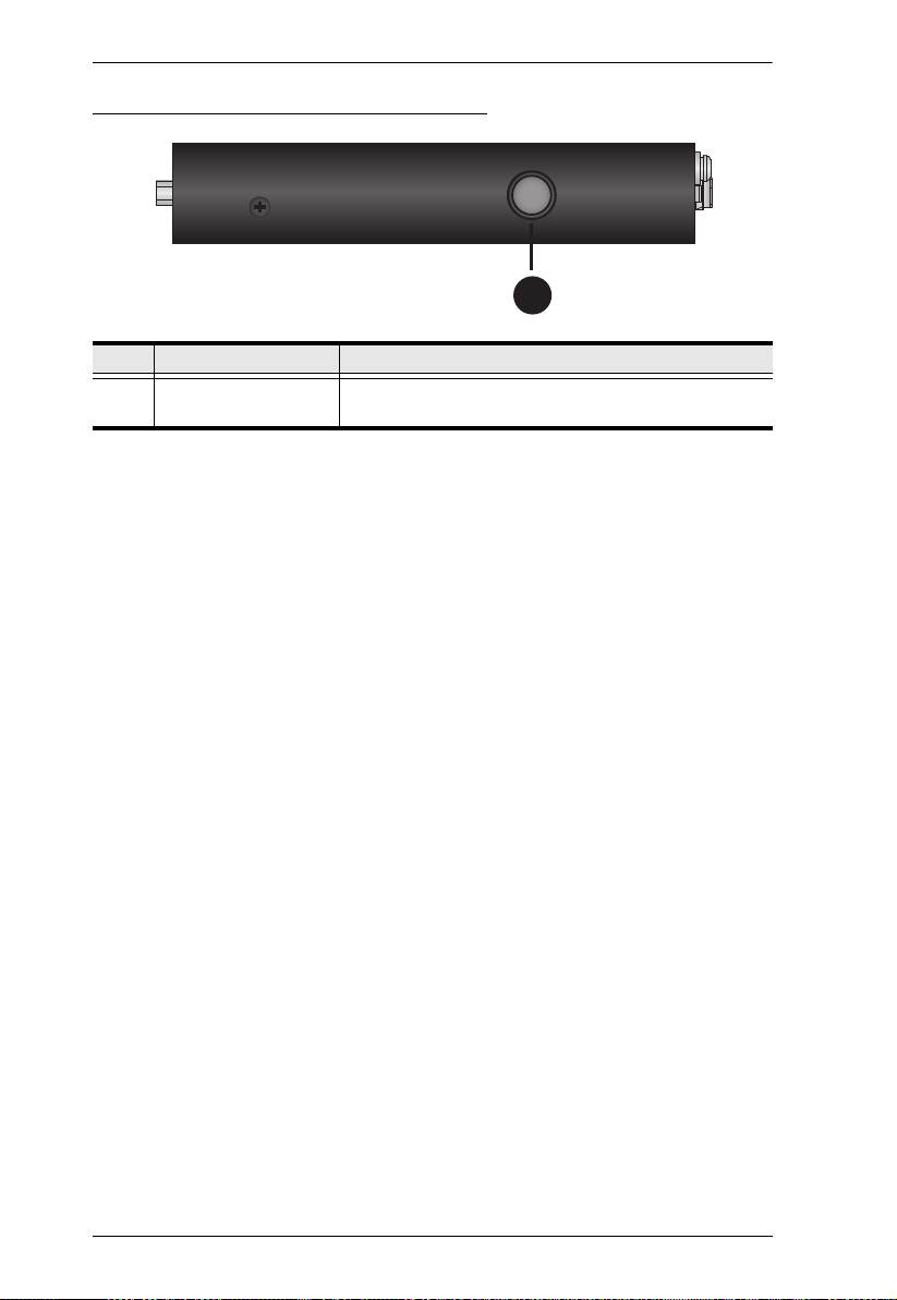
CN9000/CN9600/CN9950 Side View
No. Component Description
1 control port This port is currently non-functional for CN9000/
CN9600/CN9950.
12
Page 25

CN9950 Front View
2 3 4 5 7 8 96
No. Component Description
1PC/KVM
DisplayPort
port
Use the DisplayPort cable provided to connect the PC / server
to the 9950 through this port.
Chapter 1. Introduction
2 KVM audio
Ports
3CPU COM
(RS-232 DTE)
port
4 local console
COM (RS-232
DCE) port
5KVM USB
Type-B port
6 laptop USB
console (LUC)
port
7 reset button Press the reset button for more than 3 seconds to revert the
8 power LED Lights green when the unit is powered on.
Connect the audio of the PC / server to these ports for audio
signal transmissions.
Connect a serial data communication equipment device (e.g. a
modem or PC) to this port. See page 24 for details.
Connect a serial data terminal equipment device (e.g. a PC or
touch panel) to this port. See page 24 for details.
Use the USB cable (USB Type-A to USB Type-B) provided to
connect the PC / server to this port for keyboard and mouse
signal transmissions.
For laptop local access (See Local Access, page 115),
connect the laptop to this port using the USB Type-A to USB
Mini-B cable provided.
Make sure the mode of USB IO Settings (see USB IO
Settings, page 68) is set to LUC.
If the mode of USB IO Settings is set to Virtual Media, this port
will not work.
unit back to factory default settings.
13
Page 26

CN9000/CN9600/CN9950 User Manual
2 3 4 5 6
CN9950 Rear View
No. Component Description
1 grounding terminal Connect to a suitable grounding object.
2 power jacks Plug the power adapter provided into an AC power
3 control terminal
4 LAN ports Connect a Cat 5e/6 network cable to these ports for
5 local console ports Connect the cables for the local console (USB
source, then plug the power adapter cable into any
power jack.
Plug a second power adapter into another AC power
source, then plug the power cable into the other
CN9950’s power jack.
Note: Dual power operation is optional — the second
power source is for backup; a second power adapter
requires a separate purchase.
Connect the NC and C terminals to the PC / server
for remote reboot.
Connect the GND and DI terminals to an input
device (e.g. thermometer, humidity sensor) for digital input notification.
uplink connection.
keyboard, DisplayPort monitor, USB mouse,
microphone and speakers) to these ports. Each
connector is color coded and marked with an icon.
14
Page 27
Chapter 1. Introduction
2 3 4 5 6 7 8
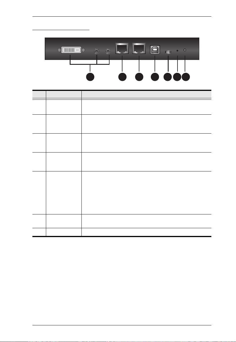
CN9600 Front View
No. Component Description
1 PC/KVM port Use the KVM cable provided to connect the PC / server to be
controlled through this port.
2CPU COM
(RS-232 DTE)
port
3 local console
COM (RS-232
DCE) port
4 USB Type-B
port
5 laptop USB
console (LUC)
port
6 reset button Press the reset button for more than 3 seconds to revert the
7 power LED Lights green when the CN9600 is powered on.
Connect a serial data communication equipment device (e.g. a
modem or PC) to this port. See page 24 for details.
Connect a serial data terminal equipment device (e.g. a PC or
touch panel) to this port. See page 24 for details.
Connect the keyboard/mouse to the server or the KVM switch
you are installing using the USB Type-A to USB Type-B cable
provided.
For laptop local access (See Local Access, page 115),
connect the laptop to this port using the USB Type-A to USB
Mini-B cable provided.
Make sure the mode of USB IO Settings (see USB IO
Settings, page 68) is set to LUC.
If the mode of USB IO Settings is set to Virtual Media, this port
will not work.
unit back to factory default settings.
15
Page 28

CN9000/CN9600/CN9950 User Manual
2 3 4 5 6
CN9600 Rear View
No. Component Description
1 grounding terminal Connect to a suitable grounding object.
2 power jacks Plug the power adapter provided with this package into
3 LAN ports Connect a Cat 5e/6 network cable to these ports for
4 control port This port is not applicable for CN9000/CN9600/
5 local console ports Connect the cables for the local console (USB
an AC power source, then plug the power adapter
cable into any power jack.
Plug a second power adapter into another AC power
source, then plug the power cable into CN9600’s other
power jack.
Note: Dual power operation is optional — the second
power source is for backup; a second power adapter
requires a separate purchase.
uplink connection.
CN9950.
keyboard, DVI monitor, USB mouse, microphone and
speakers) to these ports. Each connector is color
coded and marked with an icon.
16
Page 29
Chapter 2
1. Important safety information regarding the placement of this
device is provided on page 131. Please review it before
proceeding.
2. Make sure that the power to any device that you connect to the
installation has been turned off. You must unplug the power
cords of any computers that have the Keyboard Power On
function.
3. Any installation that does not follow the instructions in this
guide may be hazardous or cause damage to the device.
4. The power source for this product is intended to be supplied by a
power adapter only, not a DC mains.
M3 x 5
Hardware Setup
Mounting
The CN9000/CN9600/CN9950 can be mounted on most standard 19” (1U)
racks or mounted on a wall. The following illustrations are exemplified using
CN9600.
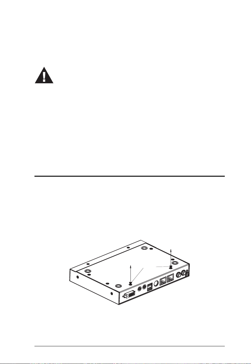
Attaching the Bracket
1. Detach the screws from the underside of the unit as shown:
2. Attach the bracket and secure the bracket using the screws from the
previous step.
17
Page 30
CN9000/CN9600/CN9950 User Manual
M3 x 5
Rack Mount
1. Position the device in the rack and align the holes in the mounting brackets
with the holes on the rack.
2. Screw the mounting bracket to the rack.
18
Page 31

Chapter 2. Hardware Setup
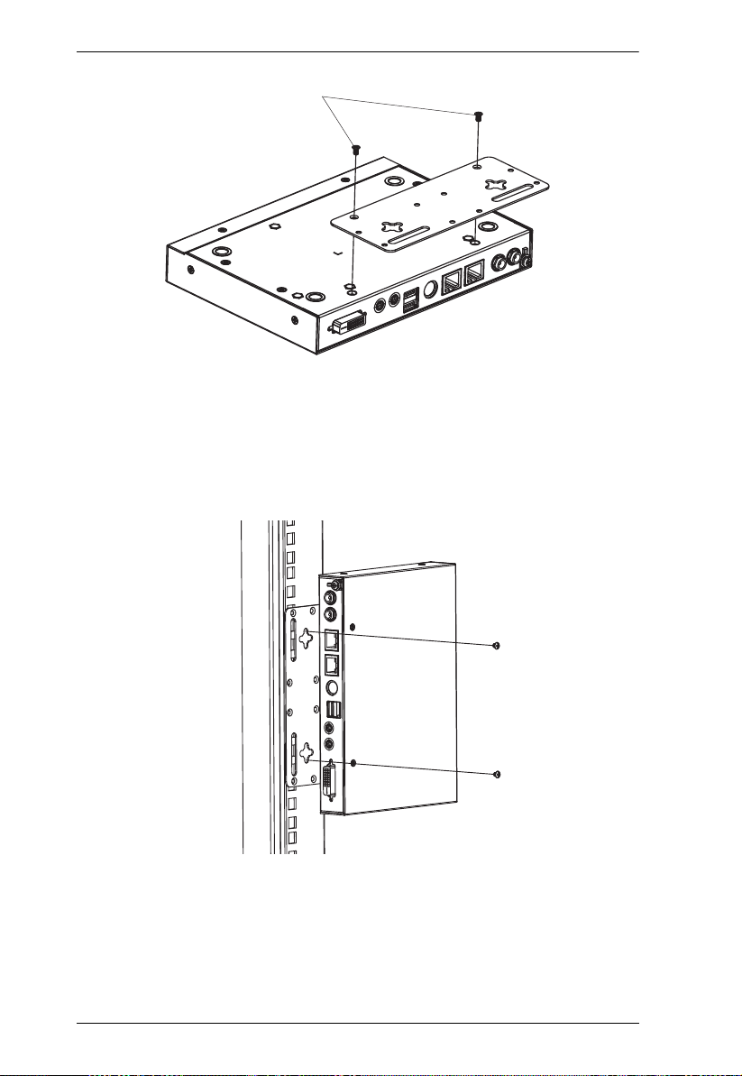
Wall Mount
CN9000/CN9600/CN9950 can be hung on a wall.
1. On the wall you wish to mount your unit, attach two screws as the hanging
hooks for the corresponding hanger keyholes of the mount bracket (you
may need to draw the positions for the screws on the wall prior to
installing), and leave enough space between the screw heads and the wall
for the keyholes, as shown below.
2. Hang the unit to the hanging hooks matching the bracket’s hanger
keyholes.
19
Page 32

CN9000/CN9600/CN9950 User Manual
Installation
Follow the steps below and refer to the diagram on the following page (the
steps and the numbers correspond to each other) to install.
1. Connect the unit’s grounding terminal to a suitable grounded object.
2. Plug your keyboard, mouse, monitor display, speakers and microphone
into the local console ports on the rear panel.
3. Using the KVM cable provided, connect the unit’s PC/KVM and audio
ports to the keyboard, video, mouse, speakers and microphone ports of the
server or KVM switch that you are installing.
4. (Optional) If you wish to access locally using the laptop USB console
(LUC) function, use the USB Type-A to USB Mini-B cable provided to
connect a USB port of the laptop to this (LUC)
Make sure you have set the mode in USB IO Setting to LUC. See p.68.
5. (Optional) If you are using serial devices (data terminal equipment), such
as a touch panel, connect it to the local console COM (RS-232 DCE) port
with a network switch console cable.
6. (Optional) If you are using serial devices (data communication
equipment), such as a PC, connect it to the CPU COM (RS-232 DTE) port
with a serial RS-232 DB-9 to RJ-45 Cat5 Ethernet adapter network
modem/switch/router cable.
port.
7. Plug a network cable into one of the unit’s LAN ports.
8. (Optional) Plug a second network cable into the other LAN port for dual
LAN operation.
9. (Optional) For CN9000/CN9950, connect the NC and C terminals to the
server or PC for remote reboot operation.
10. (Optional) For CN9000/CN9950, connect the GND and DI terminals to an
input device (e.g. thermometer, humidity sensor) for digital input
notification.
11. Plug the power adapter provided into an AC power source and plug the
power adapter cable into one of the unit’s power jacks. Now the CN9000/
CN9600/CN9950 is turned on.
12. (Optional) Plug a second power adapter into another AC power source and
plug the power cable into the other power jack for dual power operation.
20
Page 33

23 22
21
Gspou!Wjfx
Sfbs!Wjfx
Ofuxpsl
829
3
7 6
4
4
5
21
Dpouspm!Ufsnjobm
21
:
4 4
:
:
23 22
21
Gspou!Wjfx
Sfbs!Wjfx
Ofuxpsl
829
3
7 6
4
4
5
21
Dpouspm!Ufsnjobm
21
:
4 4
:
:
Chapter 2. Hardware Setup
Note: The second power connection acts as power back-up. A second power
adapter can be purchased from your ATEN supplier.
CN9000
21
Page 34

CN9000/CN9600/CN9950 User Manual
23
Gspou!Wjfx
Sfbs!Wjfx
Ofuxpsl
8 9
2
4
7 6 4
4
4
VTC!LWN!Dbcmf
Dpoofdujpo
5
2
3
22
CN9600
22
Page 35

CN9950
23 22
21
Gspou!Wjfx
Sfbs!Wjfx
Ofuxpsl
829
3
7 6
4
5
4
21
4
Dpouspm!Ufsnjobm
21
21
4
4
:
:
Chapter 2. Hardware Setup
23
Page 36

CN9000/CN9600/CN9950 User Manual
CN9000/9600/9900/9950
DCE
DTE
Switch
PC
DCE DTE
DCE
DTE
Touch Panel
PC
DCE DTE
Switch & PC
PC & Touch Panel
CN9000/9600/9900/9950
DCE and DTE Ports
You can connect different combinations of devices between DCE and DTE
ports.
If you intend to use a switch and PC combination, the switch can act as the DCE
while the PC can act as the DTE. Therefore, connect the switch to the DTE port
and the PC to the DCE port.
If you intend to use a PC and Touch Panel combination, the PC can act as the
DCE while the Touch Panel can act as the DTE. Therefore, connect the PC to
the DTE port and the Touch Panel to the DCE port.
A simple illustration is shown below:
24
Page 37

Chapter 3
Browser Login
The CN9000/CN9600/CN9950 can be accessed either from an Internet type
browser, or via the following methods:
Windows Client or Java Client (Web, Windows and Java Client Viewer,
page 76);
Windows or Java application (AP) program (The Windows Client AP,
page 77 or The Java Client AP, page 80);
Laptop USB Console (LUC) port (Laptop USB Console (LUC), page 118);
and
Local Console (see Local Console, page 115)
The next several chapters describe browser-based operations.
Logging In
To operate the CN9000/CN9600/CN9950 from a web browser, do the
following:
1. Open your browser and enter the IP address of the CN9000/CN9600/
CN9950 you want to access in the browser's URL location bar.
The default IP address for non-DHCP environment is 192.168.0.60.
Note: 1. For security purposes, a login string may have been set by the
administrator. If so, you must include a forward slash and the
login string along with the IP address when you log in. For
example:
192.168.0.100/CN9000/CN9600/CN9950
If you don’t know the IP address and login string, ask your
Administrator.
2. If you are the administrator, and are logging in for the first time,
the various ways to determine the CN9000/CN9600/CN9950’s IP
address are described in the Appendix on page 135.
2. If a Security Alert appears, click Continue to this website to accept the
certificate — it can be trusted. (See Trusted Certificates, page 143, for
details.) If a second certificate appears, accept it as well.
25
Page 38

CN9000/CN9600/CN9950 User Manual
Note: The Security Alert screen’s appearance varies depending on the
browser version.
The CN9000/CN9600/CN9950 login page appears:
3. Provide a valid username and password (set by the CN9000/CN9600/
CN9950 administrator), and click Login to continue.
Note: 1. If you are the administrator and are logging in for the first time,
use the default username (administrator) and the default
password (password). For security purposes, the system will
prompt you to change the login password. The password must be
different from your login password.
2. If you supplied an invalid login, the authentication routine will
return this message: Invalid Username or Password. Please try
again. If you see this message, log in again being mindful of the
username and password.
The main page appears after logging in successfully.
26
Page 39

Chapter 3. Browser Login
Main Screen
After you have successfully logged in, the CN9000/CN9600/CN9950 main
page appears:
The main page consists of the user menu on the left panel, with a Viewer icon
(to launch the Java or WinClient Viewer) as well as a Logout icon displayed at
the bottom of the menu.
Note: If a user does not have permission to perform a particular activity, the
menu option for that activity does not appear. See User Management,
page 30, for permission details.
27
Page 40

CN9000/CN9600/CN9950 User Manual
This Page Intentionally Left Blank
28
Page 41

Chapter 4
Configuration
Introduction
The administration utilities, represented by the links and icons located on the
left panel of the CN9000/CN9600/CN9950 web page, are used to configure the
device’s operating environment. This chapter discusses each of them in turn.
Note: 1. As you make your configuration changes in each dialog box, click
Save to apply the settings.
2. Some configuration changes only take effect after a CN9000/
CN9600/CN9950 is reset. To have the changes take effect, log out
and then log back in again.
3. If you don’t have configuration privileges (see User Management,
page 30), the Administration configuration dialogs are not available.
29
Page 42

CN9000/CN9600/CN9950 User Manual
Basic Setting
The following sections describe the screens under Basic Setting. Click the User
Management, Account Policy, Sessions and Maintenance links in the left
panel menu to view the screens.
User Management
The User Management screen allows you to add, edit or remove user accounts
to the CN9000/CN9600/CN9950, as well as modify the role and permissions
of each account:
User Information
Username: This is the user name of the account.
Password / Confirm Password: Enter a new password if you are
changing it. Re-enter the new password to confirm.
Description: Enter a descriptive word or phrase to describe the account.
Role
This allows the administrator to select which permissions the account shall be
allowed.
Administrator: Gives Administrator level access. All permissions except
View O n l y and Force to Grayscale are granted (see permissions below).
User: Gives User level access. Windows Client and Java Client
permissions are granted (see permissions below).
Select: This allows you to manually select the user’s permission in the
Permissions section.
30
Page 43

Chapter 4. Configuration
Permissions
Click to check/uncheck an item to grant/deny access to that aspect of the
CN9000/CN9600/CN9950’s operation.
Windows Client: Checking this allows a user to access the CN9000/
CN9600/CN9950 via the Windows Client software.
Config: Checking this allows the user to set up and modify the CN9000/
CN9600/CN9950's operating environment.
Telnet Client: Checking this allows a user to access the CN9000/CN9600/
CN9950 via the network protocol of the same name.
Enable Virtual Media: Checking this allows a user to utilize the CN9000/
CN9600/CN9950’s Virtual Media capabilities (see Virtual Media, page 98
for details). Use the drop down menu to select whether the user has Read/
Write, or Read Only permission.
Java Client: Checking this allows a user to access the CN9000/CN9600/
CN9950 via the Java Client software.
System Log: Checking this allows a user to view the contents of the log
file.
SSH Client: Checking this allows a user to access the CN9000/CN9600/
CN9950 via SSH sessions.
View Only: Checking this restricts a user from operating the keyboard and
the mouse.
Force to Grayscale: Checking this renders the remote display to be in
grayscale. This can speed up I/O transfer in low bandwidth situations.
After filling out the fields, click the action you want the CN9000/CN9600/
CN9950 to apply:
Reset - Click this to clear the fields.
Add - Click this to add the new account to the CN9000/CN9600/CN9950.
Update - Click this to update the settings of an existing account.
Remove - Click this to remove the selected account.
31
Page 44

CN9000/CN9600/CN9950 User Manual
Account Policy
Set the parameters for the Username and Password.
Minimum Username Length: Enter the minimum number (0 – 20) of
characters required for a username (default is 6).
Minimum Password Length: Enter the minimum number (0 – 20) of
characters required for a password (default is 6).
Password Must Contain At Least: check the checkbox to make sure the
password must contain at least One Upper Case, One Lower Case and/or
One Number character.
Note: This policy only affects user accounts created after this policy has
been enabled, as well as password changes to existing user accounts.
Check Disable Duplicate Login to ensure that only one session for each
user account is active. This prevents users from logging in with the same
account at the same time.
To prevent users from using the same password when they are required to
recreate their passwords, you can check Enforce Password History. In the
field, enter the number of password changes that must occur before a
previous password can be used a second time.
32
Page 45

Chapter 4. Configuration
Sessions
The Sessions screen lets the administrator see all the users currently logged into
the CN9000/CN9600/CN9950, and provides information about each of their
sessions.
The meanings of the headings at the top of the page are fairly straightforward.
The IP heading refers to the IP address that the user has logged in from.
The Client heading refers to the means the user employed to connect to the
CN9000/CN9600/CN9950 (Browser, WinClient AP, Java Client AP, etc.).
The Category heading lists the type of user who has logged in: Admin
(Administrator), User, or Select. (See Download, page 73 for details about
user types.)
This screen also gives the administrator the option of forcing a user to logout.
To do that, click to select the user and click End Session.
Click Refresh to update the screen.
33
Page 46

CN9000/CN9600/CN9950 User Manual
Maintenance
The Maintenance screen allows the Administrator to upgrade the CN9000/
CN9600/CN9950’s firmware, backup/restore the CN9000/CN9600/CN9950’s
configuration settings and allows you to configure the unit’s setting using
Terminal.
Upgrade Main Firmware
As new versions of the CN9000/CN9600/CN9950 firmware become available,
they can be downloaded from our website. Check the website regularly to find
the latest information and packages.
To upgrade the firmware, do the following:
1. Download the new firmware file to your computer.
2. Open your browser; log in to the CN9000/CN9600/CN9950; and click
Maintenance in the left panel menu to bring up the Firmware File dialog
box as follows:
3. Click Browse and navigate to the directory that the new firmware file is in
and select the file.
4. Click the Upgrade Firmware button.
If Check Firmware Version is enabled, when you perform an upgrade,
the current firmware level is compared with that of the upgrade file. If the
current version is higher than the upgrade version, a message appears
informing you of the fact and the procedure stops.
Note: If you want to install an older firmware version, you must uncheck
the Check Firmware Version checkbox before clicking Upgrade
Firmware.
34
Page 47

Chapter 4. Configuration
5. After the upload completes, a message appears on the screen to show you
the progress of the system upgrade.
6. When the system upgrade finishes, the current user will be logged out
automatically and the system will inform the user that the system will
reboot shortly.
Note: You will need to wait a bit before logging back in.
Update Display Information
The Update Display Information screen displays the information of the video
display and monitor used, as well as allows users to change its video resolution.
Display Information: Click to display the information of the video
display.
Update Display Info: Click to change the resolution of the video display.
Save: Click for the change to take effect.
35
Page 48

CN9000/CN9600/CN9950 User Manual
Backup / Restore
The Backup / Restore screen gives you the ability to back up the CN9000/
CN9600/CN9950’s configuration and user profile information. Backed up
User Account and Configuration information can be restored with the Restore
section. Information currently configured on the CN9000/CN9600/CN9950
will be replaced with the information that you restore.
To perform a backup, do the following:
1. (Optional) In the Password field, key in a password for the file.
Note: If you set a password, make a note of it, since you will need it to
restore the configuration later.
2. Click Backup.
3. When the browser asks what you want to do with the file, select Save and
save it to a convenient location.
Note: The CN9000/CN9600/CN9950 saves all its backup files as
sysconfig.cfg. If you want to save more than one backup file, simply
rename the file to something convenient when you save it.
36
Page 49

Chapter 4. Configuration
To restore a previous backup, do the following:
1. If a password was set when the backup was made, key the same password
that you used to save the backup file in the Password field. If a password
was not set, you can leave this field blank.
2. Click Browse and navigate to the file and select it.
3. Select which parts of the backup you wish to restore:
Select Select All to restore all information
Select User Account to only restore User Account information
Select User Select to choose which backed up information you wish to
restore. When this was selected, check/uncheck the checkbox(es) to
select/deselect what you wish to be restored.
4. When you have made your selections, click Restore.
After the file is restored, a message appears to inform you that the
procedure succeeded.
37
Page 50

CN9000/CN9600/CN9950 User Manual
Ter minal
The Terminal section allows you to configure the unit using terminal
commands.
Relay Terminal for Remote Reboot
For CN9000/CN9950 only, to set th e relay terminal to normally closed (NC)
or normally open (NO), type the corresponding command below, and press
[Enter]:
Normally closed:
Normally open:
setmotorcontrol 0
setmotorcontrol
1
Digital Input
For CN9000/CN9950 only, to check the status of the input device connected,
type
getdigitalin
and press [Enter].
For more configurable commands, type help and press [Enter].
38
Page 51

Chapter 4. Configuration
Advanced Setting
The following sections describe the administration utilities covered under
Advanced Setting, including the Device Information, Network, ANMS,
Security, Console Management, Date/Time, Customization screens.
Device Information
The Device Information screen provides information about the CN9000/
CN9600/CN9950’s status. You can change the device name in this screen.
General
Device Name: To make it easier to manage installations that have more
than one CN9000/CN9600/CN9950, each one can be given a name. Enter
a name (16 characters max.) for the CN9000/CN9600/CN9950 then click
Save.
MAC (1, 2) Address: The CN9000/CN9600/CN9950’s MAC Address
displays here.
Firmware Version / FPGA: Indicates the CN9000/CN9600/CN9950’s
current firmware version and build date. New versions of the CN9000/
CN9600/CN9950’s firmware can be downloaded from our website as they
become available (see Upgrade Main Firmware, page 34). You can
reference this number to see if there are newer versions available on the
website.
IP Address: Displays the CN9000/CN9600/CN9950’s Internet Protocol
Version 4 (32 bit) address (in the legacy format).
Subnet Mask: This is the subnet mask for the IP connection.
Gateway: This is the CN9000/CN9600/CN9950’s gateway address.
39
Page 52

CN9000/CN9600/CN9950 User Manual
IPV6 Address / IPv6 Subnet Prefix Length: Displays the CN9000/
CN9600/CN9950’s Internet Protocol Version 6 (128 bit) address (in the
new format). See IPv6, page 138 for details.
40
Page 53

Chapter 4. Configuration
Network
The Network screen is used to specify the CN9000/CN9600/CN9950’s
network environment.
41
Page 54

CN9000/CN9600/CN9950 User Manual
IP Installer
The IP Installer is an external Windows-based utility for assigning IP addresses
to the CN9000/CN9600/CN9950. Click one of the radio buttons to select
Enabled, View Only, or Disabled for the IP Installer utility. See p. 135 for IP
Installer details.
Note: 1. If you select View Only, you will be able to see the CN9000/CN9600/
CN9950 in the IP Installer’s Device List, but you will not be able to
change the IP address.
2. For security, we strongly recommend that you set this to View Only
or Disabled after using it.
Service Ports
Specify the ports that the CN9000/CN9600/CN9950 uses for various network
services.
Program: This is the port number for connecting to the CN9000/CN9600/
CN9950 from the Windows Client and Java Viewers, and from the
Windows and Java Client AP programs. The default is 9000.
HTTP: The port number for a browser login. The default is 80.
HTTPS: The port number for a secure browser login. The default is 443.
SSH: The port number for a secure shell login. The default is 22.
Tel ne t: The port number for a secure console login. The default is 23.
Note: 1. Valid entries for all of the Service Ports are from 1–65535.
2. The service ports cannot have the same value. You must set a
different value for each one.
3. If there is no firewall (on an intranet, for example), it does not matter
what these numbers are set to, since they have no effect.
If a firewall is being used, the Administrator can specify the port numbers that
the firewall will allow (and set the firewall accordingly). If a port other than the
default is set, users must specify the port number as part of the IP address when
they log in. If not, an invalid port number (or no port number) is specified, the
CN9000/CN9600/CN9950 will not be found.
42
Page 55

Chapter 4. Configuration
Redundant NIC
A Redundant NIC ensures that the CN9000/CN9600/CN9950 is always online
by switching to another network adapter in case the primary connection fails.
Check Redundant NIC if you are using the secondary LAN port for a
second IP address.
If you are using the secondary LAN port for a second IP address, leave
Redundant NIC unchecked. Use the drop-down menu and select 1000M
Network Adapter 2, then set the IP and DNS addresses for it.
IPv4 Settings
The CN9000/CN9600/CN9950 can either have its IP address assigned
dynamically at bootup (DHCP), or it can be given a fixed IP address.
For dynamic IP address assignment, select the Obtain an IP address
automatically, radio button. (This is the default setting.)
To specify a fixed IP address, select the Set IP address manually, radio
button and fill in the IP address.
Note: 1. If you choose Obtain IP address automatically, w he n t he sw it ch sta rt s
up it waits to get its IP address from the DHCP server. If it has not
obtained the address after one minute, it automatically reverts to its
factory default IP address, 192.168.0.60.
2. If the CN9000/CN9600/CN9950 is on a network that uses DHCP to
assign network addresses, and you need to ascertain its IP address,
you can use the IP installer. See IP Address Determination, page 135,
for information.
The CN9000/CN9600/CN9950 can either have its DNS server address
assigned automatically, or a fixed address can be specified.
For automatic DNS Server address assignment, select the Obtain DNS
server address automatically, radio button.
To specify a fixed address, select the Use the following DNS server
address, radio button and fill in the required information.
Note: Specifying for an alternate DNS Server address is optional.
43
Page 56

CN9000/CN9600/CN9950 User Manual
IPv6 Settings
The CN9000/CN9600/CN9950 can either have its IPv6 address assigned
dynamically at bootup (DHCP), or it can be given a fixed IPv6 address.
For dynamic IP address assignment, select the Obtain an IPv6 address
automatically radio button. (This is the default setting.)
To specify a fixed IP address, select the Set IPv6 address manually radio
button and fill in the IP address.
The CN9000/CN9600/CN9950 can either have its DNS server address
assigned automatically, or a fixed address can be specified.
For automatic DNS Server address assignment, select the Obtain DNS
server address automatically radio button.
To specify a fixed address, select the Use the following DNS server
address radio button and fill in the required information.
Note: Specifying for an alternate DNS Server address is optional.
Network Transfer Rate
This setting allows you to tailor the size of the data transfer stream to match
network traffic conditions by setting the rate at which the CN9000/CN9600/
CN9950 transfers data to remote computers. The range is from 4–99999
Kilobytes per second (KBps).
DDNS
DDNS maps a dynamic IP address assigned by a DHCP server to a host name.
The CN9000/CN9600/CN9950 can update the DDNS server with its IP
address at certain time intervals. To enable the DDNS capability for the
CN9000/CN9600/CN9950, do the following:
1. Check Enable.
2. Enter the hostname that you registered with your DDNS service provider.
3. Drop down the list to select the DDNS service you are registered with.
4. Key in the Username and Password that authenticates you with your
DDNS service.
5. In the DDNS Retry Time field, key in how many hours the CN9000/
CN9600/CN9950 waits before updating the DDNS server.
44
Page 57

Chapter 4. Configuration
ANMS
The Advanced Network Management Settings screen allows you to set up
login authentication and authorization management from external sources. It is
divided into several sections, each of which is described in the sections that
follow.
Event Destination
This section lets you configure the SMTP, Log Server, SNMP Trap and Syslog
Server settings.
45
Page 58

CN9000/CN9600/CN9950 User Manual
SMTP Settings
To have the CN9000/CN9600/CN9950 email reports from the SMTP server to
you, do the following:
1. Check Enable report from the following SMTP server and key in the IP
address and service port of your SMTP server.
2. If you’re connecting to a secure server, check My server requires secure
connection (SSL).
3. If your server requires authentication, check My server requires
authentication and key in the appropriate account information in the
Account Name and Password fields.
4. Key in the email address of where the report is being sent from in the
From field.
Note: Only one email address is allowed in the From field, and it cannot
exceed 64 English alphanumeric character.
5. Key in the email address (addresses) of where you want the SMTP reports
sent to in the To field.
Note: If you are sending the report to more than one email address,
separate the addresses with a semicolon. The total cannot exceed
256 English alphanumeric character.
6. Check the information below if you wish to include them in the report
email:
Report IP Address
Report system reboot
Report user login
Report user logout
46
Page 59

Chapter 4. Configuration
Log Server
Important operations occur on the CN9000/CN9600/CN9950, such as logins
and internal status messages, are kept in an automatically generated log file in
the Log Server. See Chapter 9, The Log Server for details on setting up the log
server. The Log File is discussed on page 121.
Check Enable to enable the Log Server function and specify the MAC address
and the Service Port of the computer the Log Server runs on.
The Log Server will listen for log details.
Note: The valid port range is 1–65535. The default port number is 9001. The
port number must different than the one used for the Program port (see
Service Ports, page 42).
SNMP Trap
To be notified of SNMP trap events, do the following:
1. Check Enable SNMP Agent.
2. Enter the Server IP and the Service Port of the computer to be notified of
SNMP trap events. The valid port range is 1-65535. Default is 162.
Note: The following SNMP trap events are sent: System Power On, Login
Failure, and System Reset.
Syslog Server
To record all the events that take place on the CN9000/CN9600/CN9950 and
write them to a Syslog server, do the following:
1. Check Enable.
2. Enter the Server IP and the Service Port of the Syslog Server. The valid
port range is 1-65535. Default is 514.
47
Page 60

CN9000/CN9600/CN9950 User Manual
Authentication
The CN9000/CN9600/CN9950 allows log in authentication and authorization
through external programs.
This screen lets you configure the RADIUS, LDAP, and CC Management
settings.
If you want to use a RADIUS, LDAP, CC Authentication instead of the
CN9000/CN9600/CN9950 device authentication, check Disable Device
Authentication. Selecting this option will disable login authentication locally
on the CN9000/CN9600/CN9950.
RADIUS Settings
To allow authentication and authorization for the CN9000/CN9600/CN9950
through a RADIUS server, do the following:
1. Check Enable.
2. Click the drop-down menu to select which you wish to set Preferred
RADIUS or Alternate RADIUS.
3. Enter the Server IP addresses and Port number.
4. Check Same as preferred setting if your Alternate RADIUS (type,
timeout, retry and secret string) is the same as the preferred.
5. In the Timeout field, set the time in seconds that the CN9000/CN9600/
CN9950 waits for a RADIUS server reply before it times out.
6. In the Retries field, set the number of allowed RADIUS retries.
7. In the Shared Secret field, enter the character string that you want to use
for authentication between the CN9000/CN9600/CN9950 and the
RADIUS Server.
48
Page 61

Chapter 4. Configuration
LDAP Settings
To allow authentication and authorization via LDAP or LDAPS, the Active
Directory’s LDAP Schema must be extended so that an extended attribute
name for the CN9600 or CN9000/CN9950 – iKVM50-userProfile or iKVM57userProfile – is added as an optional attribute to the person class.
Users can find the attribute name of CN9000/CN9600/CN9950 by executing a
get command on the Terminal page, see page 38.
In order to configure the LDAP server, you will have to complete the following
procedures: 1) Install the Windows Server Support Tools, 2) install the Active
Directory Schema Snap-in, and 3) extend and update the Active Directory
Schema.
To allow authentication and authorization for the CN9000/CN9600/CN9950
via LDAP / LDAPS, refer to the information in the following table.
Item Action
Enable Check Enable to allow LDAP / LDAPS authentication and
Preferred / Alternate
LDAP
Server IP Fill in the IP address and port number for the server. The
Port
Timeout (seconds) Set the time in seconds that the CN9000/CN9600/CN9950
Admin DN Consult the LDAP / LDAPS administrator to ascertain the
authorization.
Click for a drop-down menu to select Preferred LDAP or
Alternate LDAP.
default port numbers for LDAP and LDAPS are 389 and 636
respectively.
waits for an LDAP or LDAPS server reply before it times out.
appropriate entry for this field. For example, the entry might
look like this:
cn=LDAPAdmin,ou=cn9600,dc=aten,dc=com
49
Page 62

CN9000/CN9600/CN9950 User Manual
Item Action
Admin Name Key in the Group Name for CN9000/CN9600/CN9950
Password Key in the LDAP administrator’s password.
Search DN Set the distinguished name of the search base. This is the
administrator users.
domain name where the search starts for user names.
If Enable Authorization is not checked, this field must include
the entry where the CN9000/CN9600/CN9950 Admin Group is
created. Consult the LDAP / LDAPS administrator to ascertain
the appropriate value.
Use the following keyword for Radius and LDAP setting: su/[username]
– the username must be a real user account that exists in the local account.
For CN9600 and CN9000/CN9950, respectively use iKVM50-
userProfile and iKVM57-userProfile as LDAP attribute and su/
[username] as its attribute value.
CC Management Settings
To allow authorization for the CN9000/CN9600/CN9950 through a CC
(Control Center) server, check Enable and fill in the CC Server’s IP address
and the port that it listens on in the appropriate fields.
Note: Authentication refers to determining the authenticity of the person
logging in. Authorization refers to assigning permission to use the
device’s various functions.
50
Page 63

Chapter 4. Configuration
Security
The Security screen controls access to the CN9000/CN9600/CN9950 and
allows you configure the login failure policies, filter settings, encryption
settings, security level, working mode, private certificate and certificate
signing request.
Login Failures
For increased security, the Login Failures section allows administrators to set
policies governing what happens when a user fails to log in successfully.
The meanings of the entries are explained below.
Login Fail Policy: Select the login failure policy that the CN9000/
CN9600/CN9950 applies.
Lock Client PC – If this is enabled, after the allowed number of failures
have been exceeded, the computer attempting to log in is automatically
locked out. No logins from that computer will be accepted. The default is
unchecked. This function relates to the client computer’s IP. If the IP is
changed, the computer will no longer be locked out.
Lock Account – If this is enabled, after the allowed number of failures
have been exceeded, the user attempting to log in is automatically locked
out. No logins from the username and password that have failed will be
accepted. The default is unchecked.
Allowed – Sets the number of consecutive failed login attempts that are
permitted from a remote computer. The default is 5 times.
Timeout – Sets the amount of time (in minutes) that a remote computer
must wait before attempting to login again after it has exceeded the
number of allowed failures. The default is 3 minutes.
Note: If Login Failures is not enabled, users can attempt to log in an
unlimited number of times with no restrictions. For security purposes,
we recommend that you enable this function and enable the lockout
policies.
51
Page 64

CN9000/CN9600/CN9950 User Manual
Filter
IP and MAC Filters control access to the CN9000/CN9600/CN9950 based on
the IP and/or MAC addresses of the computers attempting to connect. A
maximum of 100 IP filters and 100 MAC filters are allowed. If any filters have
been configured, they appear in the IP Filter and/or MAC Filter list boxes.
To enable IP and/or MAC filtering, check IP Filter Enable and/or MAC
Filter Enable.
If the Include button is checked, all the addresses within the filter range
are allowed access while all other addresses are denied.
If the Exclude button is checked, all the addresses within the filter range
are denied access while all other addresses are allowed.
Adding Filters
To add an IP filter, do the following:
1. Click Add, enter the IP address range you want to filter and click OK.
2. Repeat these steps for any additional IP addresses you want to filter.
52
Page 65

Chapter 4. Configuration
To add a MAC filter, do the following:
1. Click Add. A dialog box similar to the one below appears:
2. Specify the MAC address in the dialog box and click OK.
3. Repeat these steps for any additional MAC addresses you want to filter.
Note: If there is a co nflict between an IP filter and a MAC filter – for example,
where a computer’s IP address is allowed by the IP filter but it’s MAC
address is excluded by the MAC filter – then that computer’s access is
blocked. In other words, if either filter blocks a computer, then the
computer is blocked, no matter what the other filter is set to.
Modifying Filters
To modify a filter, select it in the filter list box and click Modify. The Modify
dialog box is similar to the Add dialog box. When it comes up, simply delete
the old address(es) and replace it with the new one(s).
Deleting Filters
To delete a filter, select it in the filter list box and click Delete.
The Filter section also lets administrators specify a Login String that users must
include (in addition to the IP address) when they access the CN9000/CN9600/
CN9950 with a browser. For example:
192.168.0.126/CN9000/CN9600/CN9950
The following characters are allowed:
0–9 a–z A–Z ~ ! @ $ ^ & * ( ) _ + ‘ - = [ ] { } ; ’ < > , . |
The following characters are not allowed:
% ” : / ? # \ [Space]
Compound characters (É Ç ñ ... etc.)
Note: 1. There must be a forward slash between the IP address and the string.
2. If no login string is specified here, anyone will be able to access the
CN9000/CN9600/CN9950 login page using the IP address alone.
This makes your installation less secure.
For security purposes, we recommend that you change this string occasionally.
53
Page 66

CN9000/CN9600/CN9950 User Manual
Encryption
These flexible encryption alternatives for keyboard/mouse, video, and virtual
media data let you choose any combination of DES, 3DES, AES, RC4, or a
Random cycle of any or all of them.
Enabling encryption will affect system performance – no encryption offers the
best performance while the more encryption, the greater the adverse effect. If
you enable encryption, the performance considerations (going from best to
worst) are as follows:
RC4 offers the least performance impact, DES is next, followed by 3DES
or AES
The RC4 + DES combination offers the least impact of any combination
Security Level
For increased security, you can check or uncheck the boxes to High, Medium high, Medium or Custom security features.
1. High (Disable all services except: SSHv2, HTTPS(TLS v1.2))
2. Medium-high (Enables SSHv2, redirect HTTP to HTTPS, HTTPS(TLS
v1.2), ICMP)
3. Medium (Enables SSHv2, redirect HTTP to HTTPS, HTTPS(TLS v1.0,
1.1, 1.2), ICMP) (Default)
54
Page 67

Chapter 4. Configuration
4. Custom: Click to check the following security options you wish to apply:
Enable ICMP service
Enable Telnet service
Enable SSH session
Enable HTTP session
Enable HTTPS session (Select between “TLS 1.2”, “TLS 1.0, 1.1, 1.2”.)
Working Mode
Use this section to set the working mode parameters.
Enable FIPS for FIPS security standard. The default is Disabled.
Enable Multiuser Operation to permit more than one user to log into the
CN9000/CN9600/CN9950 at the same time. The default is Enabled.
Enable Virtual Media Write allows redirected virtual media devices on a
user’s system to send data to a remote server, as well as being able to have
data from the remote server written to them. The default is Enabled.
If Disable Authentication is checked, no authentication procedures are
used to check users attempting to log in. Users gain Administrator access
to the CN9000/CN9600/CN9950 switch simply by entering combination
of username and password. The default is Disabled.
Note: Enabling this setting creates an extremely dangerous result as far as
security goes, and should only be used under very special
circumstances.
Private Certificate
When logging in over a secure (SSL) connection, a signed certificate is used to
verify that the user is logging in to the intended site. For enhanced security, the
Private Certificate section allows you to use your own private encryption key
and signed certificate, rather than the default ATEN certificate.
55
Page 68

CN9000/CN9600/CN9950 User Manual
There are two methods for establishing your private certificate: generating a
self-signed certificate and importing a third-party certificate authority (CA)
signed certificate.
Generating a Self-Signed Certificate
If you wish to create your own self-signed certificate, a free utility –
openssl.exe – is available for download over the web. See Self-Signed Private
Certificates, page 147 for details about using OpenSSL to generate your own
private key and SSL certificate.
Obtaining a CA Signed SSL Server Certificate
For the greatest security, we recommend using a third party certificate
authority (CA) signed certificate. To obtain a third party signed certificate, go
to a CA (Certificate Authority) website to apply for an SSL certificate. After
the CA sends you the certificate, save it to a convenient location on your
computer.
Importing the Private Certificate
To import the private certificate, do the following:
1. Click Browse to the right of Private Key, navigate to where your private
encryption key file is located and select it.
2. Click Browse to the right of Certificate, navigate to where your certificate
file is located and select it.
3. Click Upload to complete the procedure.
Note: Both the private encryption key and the signed certificate must be
imported at the same time.
56
Page 69

Chapter 4. Configuration
Certificate Signing Request
The Certificate Signing Request (CSR) section provides an automated way of
obtaining and installing a CA signed SSL server certificate.
To perform this operation, do the following:
1. Click Create CSR. The following dialog box appears:
2. Fill in the form – with entries that are valid for your site – according to the
example information in the following table:
Information Example
Country (2 letter code) TW
State or Province Taiwan
Locality Taipei
Organization Your Company, Ltd.
Unit Techdoc Department
Common Name mycompany.com
Email Address administrator@yourcompany.com
This must be the exact domain name of the site that you
want the certificate to be valid for. If the site’s domain name i s
www.mycompany.com, and you only specify
mycompany.com, the certificate will not be valid.
3. After filling in the form (all fields are required), click Create.
57
Page 70

CN9000/CN9600/CN9950 User Manual
A self-signed certificate based on the information you just provided is now
stored on the CN9000/CN9600/CN9950.
4. Click Get CSR, and save the certificate file (csr.cer) to a convenient
location on your computer
This is the file that you give to the third party CA to apply for their signed
SSL certificate.
5. After the CA sends you the certificate, save it to a convenient location on
your computer. Click Browse to locate the file; then click Upload to store
it on the CN9000/CN9600/CN9950.
Note: When you upload the file, the CN9000/CN9600/CN9950 checks the
file to make sure the specified information still matches. If it does,
the file is accepted; if not, it is rejected.
If you want to remove the certificate (to replace it with a new one because of a
domain name change, for example), simply click Remove CSR.
58
Page 71

Chapter 4. Configuration
Console Management
This section discusses methods of opening the CN9000/CN9600/CN9950
console via OOBC (Out of Band Configuration) or serial connection.
OOBC
For this function to work, the serial device must be connected to the CPU COM
(RS-232 DTE) port.
When the CN9000/CN9600/CN9950 cannot be accessed with LAN-based
methods, it can be accessed via the switch’s modem port. To enable for PPP
(modem) operation, check the Enable Out of Band Access checkbox.
59
Page 72

CN9000/CN9600/CN9950 User Manual
PPP Settings
After enabling Out of Band Access, the Enable Dial Back, and Enable Dial
Out functions become available and are described in the following sections.
Dial Back
If this function is enabled, the unit disconnects calls being dialed in, and dials
back according to the options specified below:
Enable Fixed Number Dial Back: When enabled, the CN9000/CN9600/
CN9950 hangs up the modem during an incoming call, and dials back to
the modem whose phone number is specified in the Phone Number field.
Enter the phone number of the modem that you want the CN9000/
CN9600/CN9950 to dial back to in the Phone Number field.
Enable Flexible Dial Back: When enabled, CN9000/CN9600/CN9950
dials back to any modem that is convenient for the user.
Enter the password that the users must specify in the Password field.
When connecting to the CN9000/CN9600/CN9950’s modem, users will
specify the phone number of the modem that they want the CN9000/
CN9600/CN9950 to dial back to as their Username, and specify the
password set in the Password field for their password.
60
Page 73

Chapter 4. Configuration
Dial Out
For the dial out function, you must establish an account with an Internet
Service Provider, and use a modem to dial up to your ISP account. An
explanation of the Enable Dial Out items is given in the table below:
ISP Settings: Specify the telephone number, account name (username),
and password that you use to connect to your ISP.
Dial Out Schedule: This entry sets up the times you want the CN9000/
CN9600/CN9950 to dial out over the ISP connection.
Every provides a list of fixed times from every hour to every four
hours.
If you select Every two hours (for example), the CN9000/
CN9600/CN9950 will start dialing out every two hours beginning
at 00:00.
If you do not want the CN9000/CN9600/CN9950 to dial out on a
fixed schedule, select Never from the list.
61
Page 74

CN9000/CN9600/CN9950 User Manual
Daily at will dial out once a day at a specified time. Use the hh:mm
format to specify the time.
PPP online time specifies how long you want the ISP connection to
last before terminating the session and hanging up the modem. A
setting of zero means it is always online.
Emergency Dial Out: If the CN9000/CN9600/CN9950 gets disconnected
from the network, or the network goes down, this function puts the switch
online via the ISP dial up connection.
If you choose PPP stays online until network recovery, the PPP
connection to the ISP will last until the network comes back or the
switch reconnects to it.
If you choose PPP online time, the connection to the ISP will
terminate after the specified time. A setting of zero means it is always
online.
Dial Out Mail Configuration: This section provides email notification of
problems that occur on the devices connected to the CN9000/CN9600/
CN9950’s ports.
Note: This email notification differs from the one configured under SMTP
Settings in that it uses the ISP mail server rather than the internal
company’s mail server.
Enter the IPv4 address, IPv6 address, or domain name of your SMTP
server in the SMTP Server IP Address field, and enter the
corresponding port in the Service Port field.
If your server requires a secure SSL connection, check the SMTP
server requires secure connection (SSL) checkbox
If your server requires authentication, check the SMTP server
requires authentication checkbox, and enter the appropriate account
name and password in the fields below.
Enter the email address of the person responsible for the SMTP server
(or some other equally responsible administrator) in the Email From
field.
Enter the recipient email address(es) in the To field. If you are sending
the report to more than one email address, separate the addresses with a
comma or a semicolon.
62
Page 75

Chapter 4. Configuration
Serial Console
For this function to work, the serial device must be connected to the Local
Console COM (RS-232 DCE) port.
To configure the CN9000/CN9600/CN9950 to interact with the connected
serial device, you need to set its parameters to match the parameters of the
device in the Port Property Settings.
Select the values that match the ones used by the connected serial console
device. The port property settings that the CN9000/CN9600/CN9950 supports
are as follows:
Baud Rate: This sets the port’s data transfer speed. Choices are from 300–
115200 (use the drop-down menu to see them all). Set this to match the
baud rate setting of the serial console device. Default is 115200 (basic
setting for many serial console devices).
Data Bits: This sets the number of bits used to transmit one character of
data. Choices are: 7 and 8. Set this to match the data bit setting of the serial
console device. Default is 8 (which is the default for the majority of serial
console devices).
Parity: This bit checks the integrity of the transmitted data. Choices are:
None; Odd; Even. Set this to match the parity setting of the serial console
device. Default is None.
63
Page 76

CN9000/CN9600/CN9950 User Manual
CN9000/9600/9900/9950
DCE
DTE
Switch
PC
DCE DTE
Enabling Serial Port Bypass (Local Control)
PC
Touch Panel
Serial Console
(Telnet Remote Viewer)
DCE
DTE
Switch
PC
DCE DTE
Disabling Serial Port Bypass (Remote Control)
PC
Touch Panel
Serial Console
(Telnet Remote Viewer)
CN9000/9600/9900/9950
Stop Bits: This indicates that a character has been transmitted. Set this to
match the stop bit setting of the serial console device. Choices are: 1 and 2.
Default is 1 (which is the default for the majority of serial console
devices).
Flow Control: This allows you to choose how the data flow will be
controlled. Choices are: None, Hardware, and XON/XOFF. Set this to
match the flow control setting of the serial console device. Default is
None.
Note: None is only supported for baud rates of 9600 and lower. For baud
rates greater than 9600, you must choose Hardware or XON/XOFF.
Enable Serial Port Bypass: Check/uncheck to enable/disable serial port
bypass. Enabling this function allows the connected DTE device to control
your DCE device (local control) and disables serial console control
(remote control), and vice versa.
A simple diagram explaining the enabling/disabling of serial port bypass is
shown:
64
Page 77

Chapter 4. Configuration
Note: When you enable serial port bypass, Port Alert Settings will be
disabled.
Port Alert Settings: You can specify up to 10 types of events (e.g., Power
On). Enter them in the provided Alert String (1 - 10) fields.
65
Page 78

CN9000/CN9600/CN9950 User Manual
Date/Time
The Date/Time dialog page sets the CN9000/CN9600/CN9950 time
parameters:
Set the parameters according to the information below.
Time Zone
Use the drop-down menu to select the city that most closely corresponds to
where it is at.
If your country or region employs Daylight Saving Time (Summer Time),
check the corresponding checkbox.
Date / Time
Select the month from the drop-down list-box.
Click < or > to move backward or forward by one year increments.
In the calendar, click on the day.
To set the time, key in the numbers using the 24 hour HH:MM:SS format.
66
Page 79

Chapter 4. Configuration
Click Set to save your settings.
Network Time
To have the time automatically synchronized to a network time server, do the
following:
1. Check Enable auto adjustment.
2. Click the drop-down menu to select your preferred time server from the
time server list
– or –
Check Preferred custom server IP and enter the IP address of the time
server of your choice.
3. If you want to configure an alternate time server, check Alternate time
server and repeat step 2 for the alternate time server entries.
4. In Adjust time every days field, enter a number for the number of days
between synchronization procedures.
5. If you want to synchronize immediately, click Adjust Time Now.
Customization
This section provides more customizable options and are described below.
67
Page 80

CN9000/CN9600/CN9950 User Manual
Mode
Check Force All to Grayscale to enable this function. When enabled, the
remote displays of all clients connected to the CN9000/CN9600/CN9950 are
changed to grayscale. This can speed up I/O transfer in low bandwidth
situations.
Check Enable Client AP Device List to enable this function. When enabled,
the unit will be discoverable in the Server List when using the WinClient or
Java Client AP (see Starting Up, page 77). Disabling this function will render
the unit undiscoverable in the Server List but can still be connected to.
USB IO Settings
OS: Specifies the operating system that the server on the connected port is
using. Choices are Win, Mac, Sun, and Other. The default is Win.
Language: Specifies the OS language being used by the server on the
connected port. Drop down the list to see the available choices. The default is
English US.
Mode: The drop-down menu allows you to select whether you would like the
system to accept Virtual Media (see Virtual Media on page 98 for more details)
or to have local Laptop USB Console (LUC) access via the LUC Port (see
Laptop USB Console (LUC), page 118).
Multiuser Mode
Multiuser Mode: Defines how a port is to be accessed when multiple users
have logged on, as follows:
Exclusive: The first user to switch to the port has exclusive control over
the port. No other users can view the port.
Occupy: The first user to switch to the port has control over the port.
However, additional users may view the port’s video display.
Share: Users simultaneously share control over the port. Input from the
users is placed in a queue and executed chronologically. Under these
circumstances, users can take advantage of the Message Board, which
allows a user to take control of the keyboard and mouse or keyboard,
mouse, and video of a Share port (see The Message Board, page 96).
Occupy Timeout: If there is no user input for the amount of time specified
here, the control privilege is released and transferred to the next user who
moves the mouse or uses the keyboard.
68
Page 81

Chapter 4. Configuration
Exit Macro
Click the drop-down menu to select the user created system Exit Macro you
would like to use and click Save. See System Macros on page 91 for details on
creating exit macros.
Reset
Click Reset Default Values to reset the CN9000/CN9600/CN9950 to the
default system settings.
If you wish to reboot the device after you log out, check Reset on exit.
69
Page 82

CN9000/CN9600/CN9950 User Manual
Preferences
The following sections describe the administration utilities covered on this
section, including the User Preferences, Log Information, Remote Console
and Download screens.
User Preferences
The User Preferences s creen all ows the use r to set the d evice pas sword, as we ll
as device parameters including the Language, OSD Hotkey, Logout Timeout
and the Viewer.
Language
Click the drop-down menu to selects the language that the interface displays in.
OSD Hotkey
Select the keyboard combination to call the OSD function.
Logout Timeout:
When the session is idling, the time set here determines how long the CN9000/
CN9600/CN9950 will wait for before terminating the session.
Viewer
Choose the detection order for the viewer you would like to use when viewing
the remote server’s display.
Click Save for the changes to take effect.
Password
Change your password using the following fields:
70
Page 83

Chapter 4. Configuration
Old Password: Enter the old password.
New Password: Enter the new password.
Confirm Password: Repeat the new password.
Click Change Password to apply your settings.
Logs
The CN9000/CN9600/CN9950 logs all the events that take place on it.
Following a reset, all logs are cleared. Click Log Information to view the logs:
A maximum of 1024 events are kept in the log file. As new events are recorded,
they are placed at the top of the list. When a new event is recorded after there
are 1024 events in the log file, the earliest event in the list is discarded.
Note: To maintain and view a record of all the events that take place (not just
the most recent 1024), set up the Log Server AP program. See The Log
Server, page 123.
To clear the log file, click on the Clear Log icon at the lower right of the page.
71
Page 84

CN9000/CN9600/CN9950 User Manual
Remote Console
This section provides remote console related preference options.
Remote Console Preview
The preview in this screen shows a snapshot of the server’s display as follows:
Clicking Refresh updates the snapshot of the remote display.
Telnet Viewer
If the Serial Console is enabled and a user has telnet access rights, then the
“Open Tel net Client” button will appear on the Remote Console page. Click
this button to launch the built in telnet client AP.
72
Page 85

Chapter 4. Configuration
Download
The Download page lets you download the standalone Windows Client AP,
Java client AP and Log Server AP.
1. Click the button of the AP you want to download.
2. Follow the on-screen instructions to complete the installation and have the
program icon placed on your desktop.
For more information on the Windows Client AP and Java Client AP, refer
to Chapter 5 on page 75.
For details on the Log Server AP, refer to Chapter 9 on page 123.
About
Click About to see the current firmware version and copyright information of
your CN9000/CN9600/CN9950.
Viewer
Click the Viewer icon to call the remote client (Web Client, WinClient or Java
Client) to view the remote server in a separate window.
A second or two after clicking the Viewer icon, the desktop of the remote
server appears as a window on your PC. The type of viewer appearing
depends on the preference settings and the type of browser you are using.
73
Page 86

CN9000/CN9600/CN9950 User Manual
Logout
Click the Logout icon when you are done configuring the CN9000/CN9600/
CN9950’s operating environment. This logs you out of the CN9000/CN9600/
CN9950 GUI.
74
Page 87

Chapter 5
Accessing Remote Server
Introduction
The remote server can be accessed as if it were your local system. A window
will be presented and the remote server is displayed inside this window.
You can maximize the window, drag the borders to resize the window and
use the scrollbars to move around the screen.
You can switch between your local and remote programs with [Alt + Tab].
Note: 1. Due to net lag, there might be a slight delay before your keystrokes
show up. You may also have to wait a bit for the remote mouse to
catch up to your local mouse before you click.
2. Due to net lag, or insufficient computing power on the local machine,
some images, especially motion images, may display poorly.
There are several ways you can access the remote servers and are listed below:
1. Web Client viewer accessed directly from the web browser GUI. Refer to
Web, Windows and Java Client Viewer on page 76 for more information.
2. Windows viewer accessed directly from the web browser GUI. Refer to
Web, Windows and Java Client Viewer on page 76 for more information.
3. Java viewer accessed directly from the web browser GUI. Refer to Web,
Windows and Java Client Viewer on page 76 for more information.
4. Windows Client Viewer AP (without browser). Refer to The Windows
Client AP on page 77 and The Windows Client Viewer on page 81
respectively on how to access the remote server and how to utilize the
viewer.
5. Java Client Viewer AP (without browser). Refer to The Java Client AP
on page 80 on how to access the remote server. Since the control is
identical to the windows client viewer, refer to The Windows Client
Viewer on page 81 on the control of the viewer interface.
To download the Windows Client AP and the Java Client AP from the web
GUI. Refer to Download, page 73 for more details.
75
Page 88

CN9000/CN9600/CN9950 User Manual
Web, Windows and Java Client Viewer
The Web, Windows and Java Client Viewer is accessible via a web browser.
After you log into the web configuration page (see Logging In, page 25), click
the Viewer icon on the left panel menu. A second or two after, the remote
server’s desktop appears as a window on your desktop:
The control/access of the remote server is laid out in the control panel. Refer to
The Win / Java Client Control Panel on page 81 for access/control information.
By default, the Web Client viewer is used.
If you rearrange the preference order (see User Preferences, page 70), a
different Client viewer may be used.
76
Page 89

Chapter 5. Accessing Remote Server
The Windows Client AP
The Windows Client AP is a Windows Client program allowing you to access
the Windows Client without going through the browser configuration page.
Download
To download the stand-alone Windows Client program, do the following:
1. In the web GUI, go to the Download page. Refer to Download, page 73 for
more details.
2. Click the Download Windows Client AP button.
3. Save the file to a convenient location or create a shortcut on the desktop.
Starting Up
For the first time running the AP, right-click the Windows Client AP and click
“Run as administrator” to start.
The Windows Client Connection Screen is shown below and each components
are described in the table.
Server List
Item Description
When you run the CN9000/CN9600/CN9950 Windows Client
program, it automatically searches the user's local LAN
segment for CN9000/CN9600/CN9950 units, and lists
whichever ones it finds in this box. If you want to connect to
one of these units, double-click to connect.
77
Page 90

CN9000/CN9600/CN9950 User Manual
Server If the CN9000/CN9600/CN9950 you wish to connect to is at a
Connect Starts connecting to the CN9000/CN9600/CN9950.
Disconnect These buttons become active once you log into the CN9000/
Switch to remote view
Message panel The blank field on the right of the Server section shows the
1. Double-click the unit. When the CN9000/CN9600/CN9950
remote location, it will not be found on your LAN. You can
enter its IP address and port yourself.
If you don't know the Port number, contact the Administrator.
When the IP address and Port number for the unit you wish to
connect to have been specified, click Connect to start the
connection.
CN9600/CN9950. See page 79 for details.
current status of the server connection.
is
connected to
the unit, a login window appears:
2. Provide a valid Username and Password and click OK to continue.
Note: The default Username is administrator and the default Password is
password.
After you have successfully logged in, the connection screen reappears:
78
Page 91

Chapter 5. Accessing Remote Server
At this time there are two active buttons and are described in the table
below:
Button Action
Disconnect Breaks the connection to the CN9000/CN9600/CN9950.
Switch to remote
view
In some cases, administrators do not wish to have users connect
to the CN9000/CN9600/CN9950 with a browser. Switch to remote
view solves this problem as it opens a window on the user’s
desktop containing the remote server’s desktop that is the same
as the one that appears with the browser-based Windows client.
Refer to Chapter 6, The Windows Client Viewer, for operation
details.
3. Click Switch to remote view to access the remote server.
Refer to The Win / Java Client Control Panel on page 81 for information about
the remote access interface.
79
Page 92

CN9000/CN9600/CN9950 User Manual
The Java Client AP
The Java Client AP is an AP program provided to make the CN9000/CN9600/
CN9950 accessible to all platforms. It is, like the Windows Client AP, a Java
Client program allowing you to access the Java Client without going through
the browser configuration page.
Systems that have JRE 6 Update 3 or later installed can connect. Java is
available for free download from Sun’s Java web site (http://java.sun.com).
The Java Client Connection Screen and its connection steps are the same as the
Windows Client AP section. Refer to The Windows Client AP on page 77 for
more details.
Since the control/access of the remote server using the Java Client AP is also
the same as the Windows Client, refer to The Win / Java Client Control Panel
on page 81 for access/control information.
80
Page 93

Chapter 6
The Windows Client Viewer
The Win / Java Client Control Panel
The control panels of the WinClient and Java Client are similar, with their
differences explained below:
In the Macros dialog box, Toggle Mouse Display is only available on
WinClient.
The Dot mouse pointer type is only available on WinClient.
There is Show/Hide button to show or hide the user list and message panel
in the Message Board function on the Java Client Viewer. This function is
achieved by clicking the arrows at the top of the bar that separates the User
List panel from the Main panel.
In Virtual Media, only ISO and Folder are supported for Java Client.
The control panel may be hidden at the upper or lower center of the screen (the
default is up). It becomes visible when you move the mouse pointer over it:
Note: 1. The above image shows the complete Control Panel. The icons that
appear can be customized. See Control Panel Configuration,
page 107, for details.
2. To move the Control Panel to a different location on the screen, place
the mouse pointer over the text bar area, then click and drag.
The panel is consisted of two rows.
The second row shows the video resolution of the remote desktop, the bus
the user is on, and an information button where you can click it for a
menu-style version of the control panel toolbar (see below).
Right clicking the second row area also brings up the menu-style control
panel. This menu allows you to select options for the Screen Mode, Zoom,
Mouse Pointer type, and Mouse Sync Mode. These functions are discussed
in the sections that follow.
81
Page 94

CN9000/CN9600/CN9950 User Manual
Control Panel Functions
The Control Panel functions are described in the table below.
Icon Function
This is a toggle. Click to ping the Control Panel to the window where
it is always displayed on top of other screen elements. Click again to
have it display normally.
82
Click to bring up the Video Options dialog box. (See Video Settings,
page 93, for details).
Toggles the display between Full Screen Mode and Windowed
Mode.
Click to take a snapshot (screen capture) of the remote display. To
configure the Snapshot parameters, refer to Snapshot on page 108.
Click to toggle the remote display between color and grayscale.
Click to zoom the remote display window.
Note: This feature is only available in windowed mode (Full Screen
Mode is off). See Zoom, page 101 for details.
Click to send a Ctrl+Alt+Del signal to the remote system.
Page 95

Chapter 6. The Windows Client Viewer
Icon Function
Click to bring up the on-screen keyboard (see The On-Screen
Keyboard, page 102).
Click to select the mouse pointer type.
Note: This icon changes depending on which mouse pointer type is
selected (see Mouse Pointer Type, page 103).
Click to toggle Automatic or Manual mouse sync.
When the selection is Automatic, a green mark appears on the
icon.
When the selection is Manual, a red mark appears on the icon.
See Mouse DynaSync Mode, page 104 for a complete explanation
of this feature.
These icons show the Num Lock, Caps Lock, and Scroll Lock status
of the remote computer.
When the lock state is On, the LED is bright orange.
When the lock state is Off, the LED is dull blue.
Click on the icon to toggle the status.
Note: These icons and your local keyboard icons are in sync.
Clicking an icon causes the corresponding LED on your keyboard to
change accordingly. Likewise, pressing a Lock key on your
keyboard causes the icon’s color to change accordingly.
Click to bring up the Macro dialog box (see Macros, page 85 for
more details).
Click to bring up the Message Board (see The Message Board,
page 96).
Click to bring up the Virtual Media dialog box. The icon changes
when a virtual media device is mounted on the port. See Virtual
Media, page 98, for specific details.
Note: This icon displays in gray when the function is disabled or not
available to the user.
Click this to turn the speaker on or off. This icon grays out and
becomes not functional when the microphone connected to the local
console is enabled. To enable / disable the speakers from the local
console OSD, see Local OSD, page 117.
Note: The microphone connected to the local console have priority
over the speakers connected to the remote console.
83
Page 96

CN9000/CN9600/CN9950 User Manual
Icon Function
Click this to turn the microphone on or off. This icon grays out and
becomes not functional when the microphone connected to the local
console is enabled. To enable / disable the microphone from the
local console OSD, see Local OSD, page 117.
Note: The microphone connected to the local console have priority
over those connected to the remote console.
Click to access the viewer-based configuration (see Open GUI
(Configuration), page 106).
Click to bring up the Control Panel Configuration dialog box.
See Control Panel Configuration, page 107, for details on
configuring the Control Panel.
84
Page 97

Chapter 6. The Windows Client Viewer
Macros
The Macros icon provides access to three functions found in the Macros
dialog box: Hotkeys, User Macros, and System Macros. Each of these
functions is described in the following sections.
Hotkeys
Various actions, corresponding to clicking the Control Panel icons, can be
accomplished directly from the keyboard with hotkeys. Selecting the Hotkeys
radio button lets you configure which hotkeys perform the actions. The actions
are listed to the left; their hotkeys are shown to the right. Use the checkbox to
the left of an action’s name to enable or disable its hotkey.
If you find the default Hotkey combinations inconvenient, you can reconfigure
them as follows:
1. Highlight an Action, then click Set Hotkey.
2. Press your selected Function keys (one at a time). The key names appear in
the Hotkeys field as you press them.
You can use the same function keys for more than one action, as long
as the key sequence is not the same.
To cancel setting a hotkey value, click Cancel; to clear an action’s
Hotkeys field, click Clear.
3. When you have finished keying in your sequence, click Save.
85
Page 98

CN9000/CN9600/CN9950 User Manual
To reset all the hotkeys to their default values, click Reset.
An explanation of the Hotkey actions is given in the table below:
Action Explanation
Exit remote location Exits the remote view. This is equivalent to clicking the Exit icon
Adjust Video Brings up the Video Settings dialog box. This is equivalent to
Toggle Control
Panel
To gg l e M o us e
Display
Adjust mouse This synchronizes the local and remote mouse movements. The
Video Auto-sync This combination performs an auto-sync operation. It is
Show/Hide Local
Cursor
Substitute Ctrl key If your local computer captures Ctrl key combinations, preventing
Substitute Alt key Although all other keyboard input is captured and sent to the
on the Control Panel. The default keys are F2, F3, F4.
clicking the Video Settings icon on the Control Panel. The default
keys are F5, F6, F7.
Toggles the Control Panel Off and On. The default keys are F3,
F4, F5.
If you find the display of the two mouse pointers (local and
remote) to be confusing or annoying, you can use this function to
shrink the non-functioning pointer down to a barely noticeable
tiny circle, which can be ignored. Since this function is a toggle,
use the hotkeys again to bring the mouse display back to its
original configuration. This is equivalent to selecting the Dot
pointer type from the Mouse Pointer icon on the Control Panel.
The default keys are F7, F8, F9.
Note: The Java Control Panel does not have this feature.
default keys are F8, F7, F6.
equivalent to clicking the Video Autosync icon on the Control
Panel. The default keys are F6, F7, F8.
Toggles the display of your local mouse pointer off and on. This is
equivalent to selecting the Null pointer type from the Mouse
Pointer icon on the Control Panel. The default keys are F4,F5.
them from being sent to the remote system, you can implement
their effects on the remote system by specifying a function key to
substitute for the Ctrl key. If you substitute the F11 key, for
example, pressing [F11 + 5] would appear to the remote system
as [Ctrl + 5]. The default key is F11.
remote system, [Alt + Tab] and [Ctrl + Alt + Del] work on your
local computer. In order to implement their effects on the remote
system, another key may be substituted for the Alt key. If you
substitute the F12 key, for example, you would use [F12 + Tab]
and [Ctrl + F12 + Del]. The default key is F12.
86
Page 99

Chapter 6. The Windows Client Viewer
User Macros
User Macros are used to perform specific actions on the remote server. To
create the macro, do the following:
1. Select the User Macros radio button, then click Add.
2. In the dialog box that comes up, replace the “New Macro” text with a
name of your choice for the macro:
3. Click Record.
87
Page 100

CN9000/CN9600/CN9950 User Manual
The dialog box disappears, and a small panel appears at the top left of the
screen:
4. Press the keys for the macro.
To pause macro recording, click Pause. To resume, click Pause again.
Clicking Show brings up a dialog box that lists each keystroke that you
make, together with the amount of time each one takes:
Clicking Cancel cancels all keystrokes.
When you have finished, click Stop. This is the equivalent of clicking
Done in Step 5.
Note: Case is not considered – typing A or a has the same effect.
When recording the macro the focus must be on the remote
screen. It cannot be in the macro dialog box.
Only the default keyboard characters may be used. Alternate
characters cannot be used. For example, if the keyboard is
Traditional Chinese and default character is A the alternate
Chinese character obtained via keyboard switching is not
recorded.
88
 Loading...