

Multi-View KVMP™ Switch
User Manual
www.aten.com
Multi-View KVMP™ Switch User Manual
EMC Information
FEDERAL COMMUNICATIONS COMMISSION INTERFERENCE
STATEMENT: This equipment has been tested and found to comply with the
limits for a Class A digital device, pursuant to Part 15 of the FCC Rules. These
limits are designed to provide reasonable protection against harmful
interference when the equipment is operated in a commercial environment.
This equipment generates, uses, and can radiate radio frequency energy and, if
not installed and used in accordance with the instruction manual, may cause
harmful interference to radio communications. Operation of this equipment in
a residential area is likely to cause harmful interference in which case the user
will be required to correct the interference at his own expense.
The device complies with Part 15 of the FCC Rules. Operation is subject to the
following two conditions: (1) this device may not cause harmful interference,
and (2) this device must accept any interference received, including
interference that may cause undesired operation.
FCC Caution: Any changes or modifications not expressly approved by the
party responsible for compliance could void the user's authority to operate this
equipment.
Warning: Operation of this equipment in a residential environment could
cause radio interference.
Achtung: Der Gebrauch dieses Geräts in Wohnumgebung kann
Funkstörungen verursachen.
KCC Statement
RoHS
This product is RoHS compliant.
ii
Multi-View KVMP™ Switch User Manual
User Information
Online Registration
Be sure to register your product at our online support center:
International http://eservice.aten.com
Telephone Support
For telephone support, call this number:
International
China
Japan
Korea
North America
886-2-8692-6959
86-400-810-0-810
81-3-5615-5811
82-2-467-6789
1-888-999-ATEN ext 4988
1- 949-428 -1111
User Notice
All information, documentation, and specifications contained in this manual
are subject to change without prior notification by the manufacturer. The
manufacturer makes no representations or warranties, either expressed or
implied, with respect to the contents hereof and specifically disclaims any
warranties as to merchantability or fitness for any particular purpose. Any of
the manufacturer's software described in this manual is sold or licensed as is.
Should the programs prove defective following their purchase, the buyer (and
not the manufacturer, its distributor, or its dealer), assumes the entire cost of all
necessary servicing, repair and any incidental or consequential damages
resulting from any defect in the software.
The manufacturer of this system is not responsible for any radio and/or TV
interference caused by unauthorized modifications to this device. It is the
responsibility of the user to correct such interference.
The manufacturer is not responsible for any damage incurred in the operation
of this system if the correct operational voltage setting was not selected prior
to operation. PLEASE VERIFY THAT THE VOLTAGE SETTING IS
CORRECT BEFORE USE.
iii

Multi-View KVMP™ Switch User Manual
Package Contents
The CM1164A package consists of:
1 CM1164A 4-Port USB DVI Multi-View KVMP
4 KVM Cables (DVI-D, USB, Audio)
1 Power Cord
1 IR Remote Control
1 Rack Mount Kit
1 User Instructions*
The CM1284 package consists of:
1 CM1284 4-Port USB HDMI Multi-View KVMP
4 KVM Cables (HDMI, USB, Audio)
1 Power Cord
1 IR Remote Control
1 Rack Mount Kit
1 User Instructions*
TM
Switch
TM
Switch
Check to make sure that all the components are present and that nothing got
damaged in shipping. If you encounter a problem, contact your dealer.
Read this manual thoroughly and follow the installation and operation
procedures carefully to prevent any damage to the unit, and/or any of the
devices connected to it.
* Features may have been added to the Multi-View KVMP™ Switch since this
manual was printed. Please visit our website to download the most up-to-date
version.
© Copyright 2020 ATEN® International Co., Ltd.
ATEN and the ATEN logo are registered trademarks of ATEN International Co., Ltd. All rights reserved.
All other brand names and trademarks are the registered property of their respective owners.
iv
Manual Date: 2020-08-17

Multi-View KVMP™ Switch User Manual
Contents
EMC Information . . . . . . . . . . . . . . . . . . . . . . . . . . . . . . . . . . . . . . . . . . . . . ii
RoHS . . . . . . . . . . . . . . . . . . . . . . . . . . . . . . . . . . . . . . . . . . . . . . . . . . . . . ii
User Information . . . . . . . . . . . . . . . . . . . . . . . . . . . . . . . . . . . . . . . . . . . . .iii
Online Registration . . . . . . . . . . . . . . . . . . . . . . . . . . . . . . . . . . . . . . . .iii
Telephone Support . . . . . . . . . . . . . . . . . . . . . . . . . . . . . . . . . . . . . . . .iii
User Notice . . . . . . . . . . . . . . . . . . . . . . . . . . . . . . . . . . . . . . . . . . . . . .iii
Package Contents . . . . . . . . . . . . . . . . . . . . . . . . . . . . . . . . . . . . . . . . . . iv
Contents . . . . . . . . . . . . . . . . . . . . . . . . . . . . . . . . . . . . . . . . . . . . . . . . . . . v
About this Manual . . . . . . . . . . . . . . . . . . . . . . . . . . . . . . . . . . . . . . . . . . ix
Conventions . . . . . . . . . . . . . . . . . . . . . . . . . . . . . . . . . . . . . . . . . . . . . . . . x
Product Information. . . . . . . . . . . . . . . . . . . . . . . . . . . . . . . . . . . . . . . . . . . x
1. Introduction
Overview . . . . . . . . . . . . . . . . . . . . . . . . . . . . . . . . . . . . . . . . . . . . . . . . . . . 1
Features . . . . . . . . . . . . . . . . . . . . . . . . . . . . . . . . . . . . . . . . . . . . . . . . . . . 3
Requirements . . . . . . . . . . . . . . . . . . . . . . . . . . . . . . . . . . . . . . . . . . . . . . .5
Operating Systems . . . . . . . . . . . . . . . . . . . . . . . . . . . . . . . . . . . . . . . .6
Optional Equipment . . . . . . . . . . . . . . . . . . . . . . . . . . . . . . . . . . . . . . . 6
Components . . . . . . . . . . . . . . . . . . . . . . . . . . . . . . . . . . . . . . . . . . . . . . . .7
CM1164A / CM1284 Front View . . . . . . . . . . . . . . . . . . . . . . . . . . . . . . 7
CM1164A Rear View . . . . . . . . . . . . . . . . . . . . . . . . . . . . . . . . . . . . . . 9
CM1284 Rear View . . . . . . . . . . . . . . . . . . . . . . . . . . . . . . . . . . . . . . 10
IR Remote Control . . . . . . . . . . . . . . . . . . . . . . . . . . . . . . . . . . . . . . .11
2. Hardware Setup
Rack Mounting . . . . . . . . . . . . . . . . . . . . . . . . . . . . . . . . . . . . . . . . . . . . . 13
Installation . . . . . . . . . . . . . . . . . . . . . . . . . . . . . . . . . . . . . . . . . . . . . . . . 15
CM1164A . . . . . . . . . . . . . . . . . . . . . . . . . . . . . . . . . . . . . . . . . . . . . .15
Single Station Installation . . . . . . . . . . . . . . . . . . . . . . . . . . . . . . . 15
Single Station Installation Diagram . . . . . . . . . . . . . . . . . . . . . . . . 16
Daisy Chaining . . . . . . . . . . . . . . . . . . . . . . . . . . . . . . . . . . . . . . .17
Daisy Chain Installation Diagram. . . . . . . . . . . . . . . . . . . . . . . . . . 18
Cascading . . . . . . . . . . . . . . . . . . . . . . . . . . . . . . . . . . . . . . . . . . . 19
Cascade Installation Diagram . . . . . . . . . . . . . . . . . . . . . . . . . . . .20
CM1284 . . . . . . . . . . . . . . . . . . . . . . . . . . . . . . . . . . . . . . . . . . . . . . . 21
Single Station Installation . . . . . . . . . . . . . . . . . . . . . . . . . . . . . . . 21
Single Station Installation Diagram . . . . . . . . . . . . . . . . . . . . . . . . 22
Daisy Chaining . . . . . . . . . . . . . . . . . . . . . . . . . . . . . . . . . . . . . . .23
Daisy Chain Installation Diagram. . . . . . . . . . . . . . . . . . . . . . . . . . 24
Cascading . . . . . . . . . . . . . . . . . . . . . . . . . . . . . . . . . . . . . . . . . . . 25
Cascade Installation Diagram . . . . . . . . . . . . . . . . . . . . . . . . . . . .26
3. Basic Operation
v

Multi-View KVMP™ Switch User Manual
Overview. . . . . . . . . . . . . . . . . . . . . . . . . . . . . . . . . . . . . . . . . . . . . . . . . . 27
Identifying the Source Device. . . . . . . . . . . . . . . . . . . . . . . . . . . . . . . . . . 27
Switching . . . . . . . . . . . . . . . . . . . . . . . . . . . . . . . . . . . . . . . . . . . . . . . . . 29
Front Panel Pushbuttons. . . . . . . . . . . . . . . . . . . . . . . . . . . . . . . . . . . 29
LED Display. . . . . . . . . . . . . . . . . . . . . . . . . . . . . . . . . . . . . . . . . . 30
Hotkey Switching . . . . . . . . . . . . . . . . . . . . . . . . . . . . . . . . . . . . . . . . 31
IR Remote Switching . . . . . . . . . . . . . . . . . . . . . . . . . . . . . . . . . . . . . 31
OSD Switching . . . . . . . . . . . . . . . . . . . . . . . . . . . . . . . . . . . . . . . . . . 32
Boundless Switching. . . . . . . . . . . . . . . . . . . . . . . . . . . . . . . . . . . . . . 33
Multiview Monitor Layout Rule . . . . . . . . . . . . . . . . . . . . . . . . . . . 33
Tier (Chain Vert) Layout . . . . . . . . . . . . . . . . . . . . . . . . . . . . . . . . 34
Row (Chain Horz) Layout . . . . . . . . . . . . . . . . . . . . . . . . . . . . . . . 34
Quarter (Chain 2 x 2) Layout. . . . . . . . . . . . . . . . . . . . . . . . . . . . . 34
Display Modes . . . . . . . . . . . . . . . . . . . . . . . . . . . . . . . . . . . . . . . . . . . . . 35
Full Screen . . . . . . . . . . . . . . . . . . . . . . . . . . . . . . . . . . . . . . . . . . . . . 35
Quad View . . . . . . . . . . . . . . . . . . . . . . . . . . . . . . . . . . . . . . . . . . . . . 37
Picture in Picture - Dual . . . . . . . . . . . . . . . . . . . . . . . . . . . . . . . . . . . 38
Picture in Picture - Triple . . . . . . . . . . . . . . . . . . . . . . . . . . . . . . . . . . 39
Picture in Picture - Quad . . . . . . . . . . . . . . . . . . . . . . . . . . . . . . . . . . 40
Picture on Picture . . . . . . . . . . . . . . . . . . . . . . . . . . . . . . . . . . . . . . . . 41
Picture by Picture - Dual . . . . . . . . . . . . . . . . . . . . . . . . . . . . . . . . . . 42
Picture by Picture - Triple . . . . . . . . . . . . . . . . . . . . . . . . . . . . . . . . . . 43
Picture by Picture - Quad . . . . . . . . . . . . . . . . . . . . . . . . . . . . . . . . . . 44
Preset Configuration . . . . . . . . . . . . . . . . . . . . . . . . . . . . . . . . . . . . . . . . 45
4. Hotkey Operation
Open the OSD Menu . . . . . . . . . . . . . . . . . . . . . . . . . . . . . . . . . . . . . . . . 47
The Hotkey Setting Mode . . . . . . . . . . . . . . . . . . . . . . . . . . . . . . . . . . . . 48
Hotkeys List. . . . . . . . . . . . . . . . . . . . . . . . . . . . . . . . . . . . . . . . . . 49
Auto Scanning . . . . . . . . . . . . . . . . . . . . . . . . . . . . . . . . . . . . . . . . . . 53
Auto Scanning - Display Modes . . . . . . . . . . . . . . . . . . . . . . . . . . 53
5. OSD Operation
Overview. . . . . . . . . . . . . . . . . . . . . . . . . . . . . . . . . . . . . . . . . . . . . . . . . . 55
The Quick Access Toolbar . . . . . . . . . . . . . . . . . . . . . . . . . . . . . . . . . . . . 55
The Editor Mode . . . . . . . . . . . . . . . . . . . . . . . . . . . . . . . . . . . . . . . . . . . 57
The OSD Menu . . . . . . . . . . . . . . . . . . . . . . . . . . . . . . . . . . . . . . . . . . . . 59
Password Protection . . . . . . . . . . . . . . . . . . . . . . . . . . . . . . . . . . . . . 60
System Settings . . . . . . . . . . . . . . . . . . . . . . . . . . . . . . . . . . . . . . . . . 61
6. RS-232 Operation
Overview. . . . . . . . . . . . . . . . . . . . . . . . . . . . . . . . . . . . . . . . . . . . . . . . . . 67
Setup . . . . . . . . . . . . . . . . . . . . . . . . . . . . . . . . . . . . . . . . . . . . . . . . . . . . 67
RS-232 Pin Assignments . . . . . . . . . . . . . . . . . . . . . . . . . . . . . . . . . . 68
RS-232 Commands . . . . . . . . . . . . . . . . . . . . . . . . . . . . . . . . . . . . . . . . . 69
Verification Messages . . . . . . . . . . . . . . . . . . . . . . . . . . . . . . . . . . . . 69
vi

Multi-View KVMP™ Switch User Manual
Log In . . . . . . . . . . . . . . . . . . . . . . . . . . . . . . . . . . . . . . . . . . . . . . . . .70
Logout . . . . . . . . . . . . . . . . . . . . . . . . . . . . . . . . . . . . . . . . . . . . . . . . 71
Open/Close RS-232 Link . . . . . . . . . . . . . . . . . . . . . . . . . . . . . . . . . .72
Switch Port . . . . . . . . . . . . . . . . . . . . . . . . . . . . . . . . . . . . . . . . . . . . .73
Switch Port (KVM Focus only) . . . . . . . . . . . . . . . . . . . . . . . . . . . . . . 74
Switch Port (USB Peripherals Focus only) . . . . . . . . . . . . . . . . . . . . .75
Switch Port (Audio Focus only) . . . . . . . . . . . . . . . . . . . . . . . . . . . . .76
Daisy-Chained Boundless Switching . . . . . . . . . . . . . . . . . . . . . . . . . 77
PiP Mode . . . . . . . . . . . . . . . . . . . . . . . . . . . . . . . . . . . . . . . . . . . . . . 78
Quad View Mode . . . . . . . . . . . . . . . . . . . . . . . . . . . . . . . . . . . . . . . . 79
Change Display Mode . . . . . . . . . . . . . . . . . . . . . . . . . . . . . . . . . . . . 80
Port Disable . . . . . . . . . . . . . . . . . . . . . . . . . . . . . . . . . . . . . . . . . . . .81
OSD Language . . . . . . . . . . . . . . . . . . . . . . . . . . . . . . . . . . . . . . . . . .82
Keyboard Language Layout . . . . . . . . . . . . . . . . . . . . . . . . . . . . . . . . 83
Set Operating System . . . . . . . . . . . . . . . . . . . . . . . . . . . . . . . . . . . .84
Auto Scan . . . . . . . . . . . . . . . . . . . . . . . . . . . . . . . . . . . . . . . . . . . . . . 85
Port ID Display . . . . . . . . . . . . . . . . . . . . . . . . . . . . . . . . . . . . . . . . . .86
Security . . . . . . . . . . . . . . . . . . . . . . . . . . . . . . . . . . . . . . . . . . . . . . .87
Station . . . . . . . . . . . . . . . . . . . . . . . . . . . . . . . . . . . . . . . . . . . . . . . .88
DCC Control . . . . . . . . . . . . . . . . . . . . . . . . . . . . . . . . . . . . . . . . . . . . 89
Mouse Emulation . . . . . . . . . . . . . . . . . . . . . . . . . . . . . . . . . . . . . . . .90
Keyboard Emulation . . . . . . . . . . . . . . . . . . . . . . . . . . . . . . . . . . . . . . 91
Video DynaSync . . . . . . . . . . . . . . . . . . . . . . . . . . . . . . . . . . . . . . . . .92
Hardware Cursor . . . . . . . . . . . . . . . . . . . . . . . . . . . . . . . . . . . . . . . . 93
Activate Beeper . . . . . . . . . . . . . . . . . . . . . . . . . . . . . . . . . . . . . . . . .94
Hotkey Setting . . . . . . . . . . . . . . . . . . . . . . . . . . . . . . . . . . . . . . . . . .95
OSD Hotkey . . . . . . . . . . . . . . . . . . . . . . . . . . . . . . . . . . . . . . . . . . . . 96
Power on Detection . . . . . . . . . . . . . . . . . . . . . . . . . . . . . . . . . . . . . . 97
Fn Key . . . . . . . . . . . . . . . . . . . . . . . . . . . . . . . . . . . . . . . . . . . . . . . .98
USB Reset . . . . . . . . . . . . . . . . . . . . . . . . . . . . . . . . . . . . . . . . . . . . . 99
Restore Default Value . . . . . . . . . . . . . . . . . . . . . . . . . . . . . . . . . . .100
Firmware Upgrade . . . . . . . . . . . . . . . . . . . . . . . . . . . . . . . . . . . . . .101
KVM Status . . . . . . . . . . . . . . . . . . . . . . . . . . . . . . . . . . . . . . . . . . . 102
Hotkey List . . . . . . . . . . . . . . . . . . . . . . . . . . . . . . . . . . . . . . . . . . . . 103
Info . . . . . . . . . . . . . . . . . . . . . . . . . . . . . . . . . . . . . . . . . . . . . . . . . . 104
Display B . . . . . . . . . . . . . . . . . . . . . . . . . . . . . . . . . . . . . . . . . . . . .105
7. System Maintenance
Firmware Upgrades. . . . . . . . . . . . . . . . . . . . . . . . . . . . . . . . . . . . . . . . .107
Backup / Restore . . . . . . . . . . . . . . . . . . . . . . . . . . . . . . . . . . . . . . . . . . 111
Powering Off and Restarting . . . . . . . . . . . . . . . . . . . . . . . . . . . . . . . . .114
Restoring to Default Settings . . . . . . . . . . . . . . . . . . . . . . . . . . . . . . . . . 114
Appendix
Safety Instructions. . . . . . . . . . . . . . . . . . . . . . . . . . . . . . . . . . . . . . . . . . 115
General . . . . . . . . . . . . . . . . . . . . . . . . . . . . . . . . . . . . . . . . . . . . . . . 115
vii

Multi-View KVMP™ Switch User Manual
Rack Mounting . . . . . . . . . . . . . . . . . . . . . . . . . . . . . . . . . . . . . . . . . 117
Technical Support . . . . . . . . . . . . . . . . . . . . . . . . . . . . . . . . . . . . . . . . . 118
International . . . . . . . . . . . . . . . . . . . . . . . . . . . . . . . . . . . . . . . . . . . 118
North America . . . . . . . . . . . . . . . . . . . . . . . . . . . . . . . . . . . . . . . . . 118
Specifications . . . . . . . . . . . . . . . . . . . . . . . . . . . . . . . . . . . . . . . . . . . . . 119
Troubleshooting . . . . . . . . . . . . . . . . . . . . . . . . . . . . . . . . . . . . . . . . . . . 121
Fn Key Reference . . . . . . . . . . . . . . . . . . . . . . . . . . . . . . . . . . . . . . . . . 122
Mac Keyboard Emulation . . . . . . . . . . . . . . . . . . . . . . . . . . . . . . . . . . . . 123
Sun Keyboard Emulation . . . . . . . . . . . . . . . . . . . . . . . . . . . . . . . . . . . . 124
Factory Default Hotkeys and Settings . . . . . . . . . . . . . . . . . . . . . . . . . . 125
Limited Warranty. . . . . . . . . . . . . . . . . . . . . . . . . . . . . . . . . . . . . . . . . . . 126
viii

Multi-View KVMP™ Switch User Manual
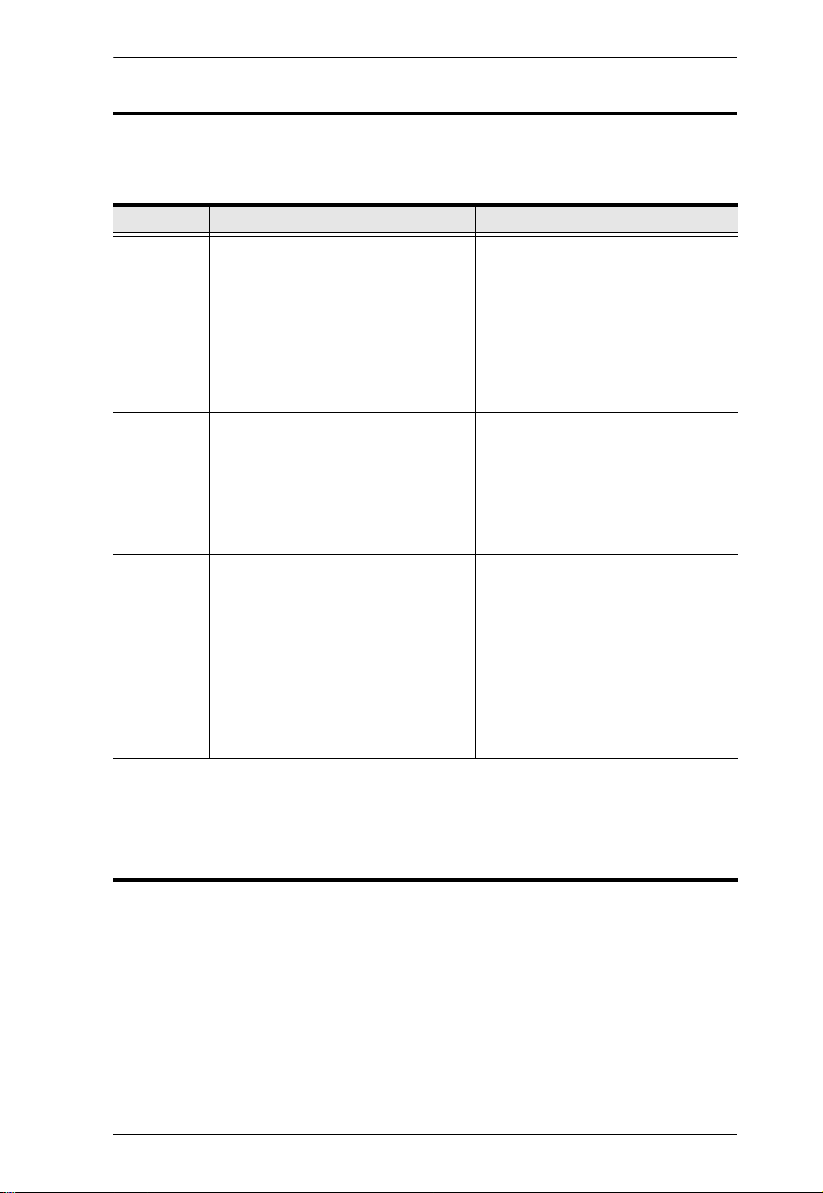
About this Manual
This User Manual is provided to help you get the most from your system. It
covers all aspects of installation, configuration, and operation for the following
models of the Multi-View KVMP™ Switch:
Model Product Name
CM1164A
CM1284
4-Port USB DVI Multi-View KVMP
4-Port USB HDMI Multi-View KVMP
An overview of the information found in the manual is provided below.
Chapter 1, Introduction, introduces you to the Multi-View KVMP™
Switch. Its purpose, features and benefits are presented, and its front and back
panel components are described.
Chapter 2, Hardware Setup, describes how to set up your installation.
Diagrams showing the necessary steps are provided.
Chapter 3, Basic Operation, explains the fundamental concepts involved
in operating the Multi-View KVMP™ Switch.
Chapter 4, Hotkey Operation, details all of the concepts and procedures
involved in the hotkey operation of your Multi-View KVMP™ Switch.
TM
Switch
TM
Switch
Chapter 5, OSD Operation, provides a complete description of the
Multi-View KVMP™ Switch’s On-Screen Display (OSD), and how to work
with it.
Chapter 6, RS-232 Operation, provides details on the functions and
RS-232 commands that you can use to control the Multi-View KVMP™
Switch using a serial controller.
Chapter 7, System Maintenance, provides step-by-step information on
firmware upgrades, restoring the device default, and how to safely restart your
Multi-View KVMP™ Switch.
Appendix, provides specifications and other technical information
An
regarding the Multi-View KVMP™ Switch.
ix
Multi-View KVMP™ Switch User Manual
Conventions
This manual uses the following conventions:
Monospaced Indicates text that you should key in.
[ ] Indicates keys you should press. For example, [Enter] means to
press the Enter key. If keys need to be chorded, they appear
together in the same bracket with a plus sign between them:
[Ctrl+Alt].
1. Numbered lists represent procedures with sequential steps.
♦ Bullet lists provide information, but do not involve sequential steps.
→ Indicates selecting the option (on a menu or dialog box, for
example), that comes next. For example, Start
open the Start menu, and then select Run.
Indicates critical information.
Product Information
→
Run means to
For information about all ATEN products and how they can help you connect
without limits, visit ATEN on the Web or contact an ATEN Authorized
Reseller. Visit ATEN on the Web for a list of locations and telephone numbers:
International http://www.aten.com
North America http://www.aten-usa.com
x

Chapter 1
Introduction
Overview
The Multi-View KVMP™ Switch charts a revolutionary new direction in
KVM switch functionality by combining a 4-port DVI-D (CM1164A) / 4-port
HDMI (CM1284) with a 2-port USB hub, and providing different display
modes, including Quad View mode, Picture in Picture mode (Dual, Triple, or
Quad), Picture by Picture mode (Dual, Triple, or Quad), Picture on Picture
mode, and Full Screen mode. Control and switch between computers/video
sources is versatile using the front-panel pushbuttons, IR remote control, OnScreen Display (OSD), RS-232 commands, or through hotkey combinations
entered from the console keyboard.
The Multi-View KVMP™ Switch allows users to access 4 computers/devices
from a single console, consisting of a USB keyboard, USB mouse, and DVI-D
(CM1164A) or HDMI (CM1284) monitor. With the CM1284, you can connect
up to two monitors – one acts as the main control and supports all the display
modes, and the other acts as a secondary display that only shows a channel
selected from the main monitor in full-screen mode. Video switching for the
second monitor is easy with Boundless Switching which allows you to switch
channels simply by moving the console mouse to the desired channel on the
main display.
As a USB hub, the Multi-View KVMP™ Switch permits each computer to
access connected peripherals on a one-computer-at-a-time basis. The MultiView KVMP™ Switch’s independent switching feature allows the KVM focus
to be on one computer while the USB peripheral focus is on another. There is
no need to purchase a separate USB hub, as well as separate stand-alone
peripheral sharers.
The Multi-View KVMP™ Switch further improves on previous designs with
DVI-D (CM1164A) or HDMI (CM1284) connectors, and the transfer of
keyboard and mouse data to the computers via a fast, reliable USB connection.
As with the USB peripherals, the audio focus can be independent of the KVM
focus.
1

Multi-View KVMP™ Switch User Manual
A Daisy Chain Control (DCC) port allows the user to connect and control up
to four Multi-View KVMP™ Switches via a single set of keyboard and mouse.
This enables the use of only one keyboard/mouse over several computers by
switching the console keyboard and mouse focus to the monitor of each
secondary station. This is convenient for growing networks that need to
monitor and manage more computers – daisy chain up to four units and switch
between up to 16 computers/video sources. You can also choose to have all
sources displayed on one monitor by cascading, where CM1164A/CM1284
units are connected to one another via its KVM Ports. In a cascade setup, you
can control and monitor up to 16 computers (4 additional Multi-View
KVMP™ Switches) using a single console.
Setup is fast and easy; simply plug cables into their appropriate ports. There is
no software to configure, no installation routines, and no incompatibility
problems. Since the Multi-View KVMP™ Switch intercepts keyboard input
directly, it works on Microsoft Windows, Linux, Sun and Mac platforms.
The Multi-View KVMP™ Switch improves operational efficiency for a wide
range of practical applications, including control rooms, monitoring systems,
and traffic control centers, as well as process control centers, server rooms,
medical industries, broadcasting, production and automation, aircraft and
vehicles. In combination with projectors, it is also used in presentations and
conference rooms. Allowing you to switch seamlessly between four PCs, and
share USB peripherals and stereo audio, the Multi-View KVMP™ Switch is
ideal for multimedia applications, and offers the ultimate in space-saving,
streamlined KVM technology.
2

Chapter 1. Introduction
Features
Multi-view modes allow users to view and control up to four video
channels on one screen with display modes including Quad View, Picture
in Picture (PiP), Picture by Picture (PbP), and Picture on Picture (PoP)
The CM1284 supports dual video outputs on the console side. The primary
monitor provides multi-view modes.
Easy resizing and/or repositioning of PiP or PbP to suit users’ viewing
needs
System configuration (display mode and KVM port selection) via the front
panel, OSD, IR Remote control, and RS-232 commands
Superior video quality – Up to 4K (4096 x 2160 @ 30 Hz) (CM1284 only)
Drop-down menu – edit display windows and other functions with the
console mouse and on-screen control panel
KVM port selection via the front-panel pushbuttons, hotkeys, mouse, and
RS-232 serial commands
Boundless Switching – Simply move the mouse cursor across windows to
switch to other video sources even among the daisy chained installation
Boundless Switching Focus - a window frame to indicate which computer
that it currently has the focus
Video DynaSync™ – exclusive ATEN technology that eliminates boot-up
display problems and optimizes the resolution when switching among
different sources
EDID Expert™ – Selects optimum EDID settings for smooth power-up,
high-quality display and use of the best video resolution across different
screens
DCC (Daisy Chain Control) – Controls up to 3 additional Multi-View
KVMP™ Switches from a single console
Cascade up to 2 levels – Controls up to 16 computers (with up to 4 x 4
multi-view mode)
HDCP 1.4 compliant
Console keyboard emulation / bypass feature that support most
multimedia keyboards
Console mouse port emulation / bypass feature that supports most mouse
drivers and multifunction mice
1
3

Multi-View KVMP™ Switch User Manual
Independent switching for USB peripheral port, stereo audio, and KVM
switch focus
Power on detection
Auto Scan feature
Firmware upgradeable via computer’s USB port
Full base response that provides a rich experience for 2.0 channel audio
Multilingual keyboard mapping – supports English, French, Japanese, and
German keyboards
Hot-pluggable
Supports keyboard combinations via emulation (for Sun / Mac)
2
Note:
1. Mouse port switching is only workable under the mouse emulation mode
and applicable to 3-key USB wheel mouses only.
2. PC keyboard combinations emulate Mac keyboard. Mac keyboard only
work with their computers.
4
Chapter 1. Introduction
Requirements
Refer to the table below to prepare the required devices, equipment, and cables
to set up a CM1164A/CM1284 system.
CM1164A CM1284
Console
Computers Each computer
Cables
Note:
1. Make sure the computers’ operating systems are supported. For information, see
Operating Systems, page 6.
2. The quality of the display is affected by the quality of the computer’s graphics card.
ATEN recommends using a high quality product.
1 x DVI-D Single Link display
capable of the highest possible
resolution
1 x USB mouse
1 x USB keyboard
(Optional) Microphone and
speakers
1
must be equipped
with the following:
1 x DVI port
1 x USB Type A port
(Optional) Audio ports
1 x KVM cable (Single Link DVID, 2.0 channel audio, USB 2.0)
1 x IEC320 Power Cord
1 x Cat 5 cable with an RJ-45
connector for Daisy Chain
Control
1 x IR Extension cable (sold
separately)
2
1 x HDMI cable
1 x USB mouse
1 x USB keyboard
(Optional) Microphone and
speakers
Each computer
with the following:
1 x HDMI port
1 x USB Type A port
(Optional) Audio ports
1 x KVM cable (HDMI, 2.0
channel audio, USB 2.0)
1 x IEC320 Power Cord
1 x Cat 5 cable with an RJ-45
connector for Daisy Chain
Control
1 x IR Extension cable (sold
separately)
1
must be equipped
2
5

Multi-View KVMP™ Switch User Manual
Operating Systems
Supported operating systems are shown in the table below:
OS Version
Windows 7, 8.1, 10
Linux RedHat CentOS 7, Ubuntu 16.04
SuSE OpenSuSE 13.2
UNIX Sun 10
Novell Netware X
Mac 10.12
Optional Equipment
An IR extension cable is available for the Multi-View KVMP™ Switch but is
sold separately. To purchase the IR extension cable, contact your ATEN dealer
and refer to the item’s part number, 2XRT-0003G.
6
Chapter 1. Introduction
1
2 2
3
4
5 6 7 8 9
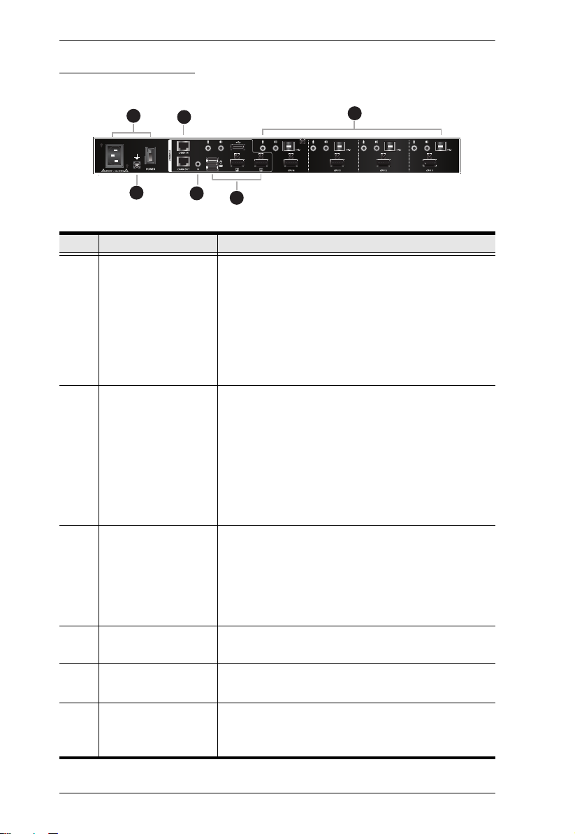
Components
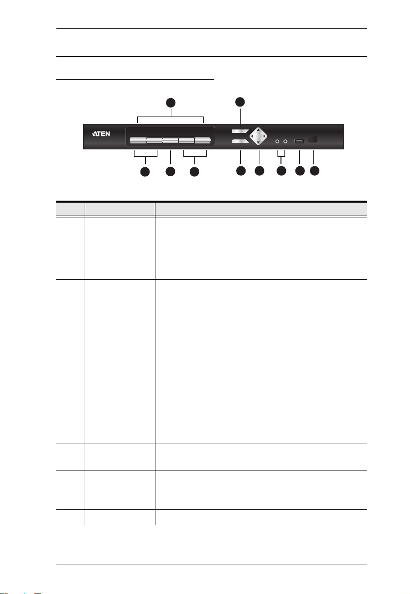
CM1164A / CM1284 Front View
No. Component Description
1 KVM Status Panel This panel contains LED icons that light to indicate mode
and port status. The Mode and KVM Port Selection
Pushbuttons each have three corresponding LED icons
that represent audio, KVM, and USB Link status. See
Display Modes, page 35, for full details.
2KVM Port
Selection
Pushbuttons
3 Mode Selection
Pushbutton
4 OSD (Esc) button Press this to invoke the on-screen display (OSD) Menu.
5 Select button Press this to select an option in the OSD Menu.
Press the KVM Port Selection Pushbuttons to manually
switch ports. See Display Modes, page 35, for full
details.
In a cascade setup, press a KVM Port Selection
Pushbutton to switch the console display to the
TM
corresponding secondary KVMP
Press and hold KVM Port Selection Pushbuttons 1 and
2 simultaneously for 2 seconds to start Auto Scan Mode.
See Auto Scanning, page 53, for full details.
Press and hold KVM Port Selection Pushbuttons 3 and
4 simultaneously for 2 seconds to detect the console
keyboard and mouse again.
This pushbutton allows you to cycle through the three
modes of focus – KVM, stereo audio, and USB Link.
When the OSD Menu is enabled, press the OSD button to
go back to the previous menu/submenu.
Switch.
7
Multi-View KVMP™ Switch User Manual
No. Component Description
6 Direction /
Function buttons
7 Console Audio
Ports
8USB 2.0
Peripheral Port
9 IR Receiver This receives signals from the IR remote control.
Use these buttons to:
Switch between different preset configurations (Fn1 to
Fn4). For details about Function modes, see Preset
Configuration, page 45.
Cycle through the OSD Menu/selection. See IR
Remote Control, page 11 for details.
Your speakers and microphone plug in here.
Note: When both the front-panel and rear-panel audio
ports are used, the front panel takes priority.
USB 2.0 peripherals (printers, scanners, etc.) plug into this
port.
8
Chapter 1. Introduction
32
4
1
5
6
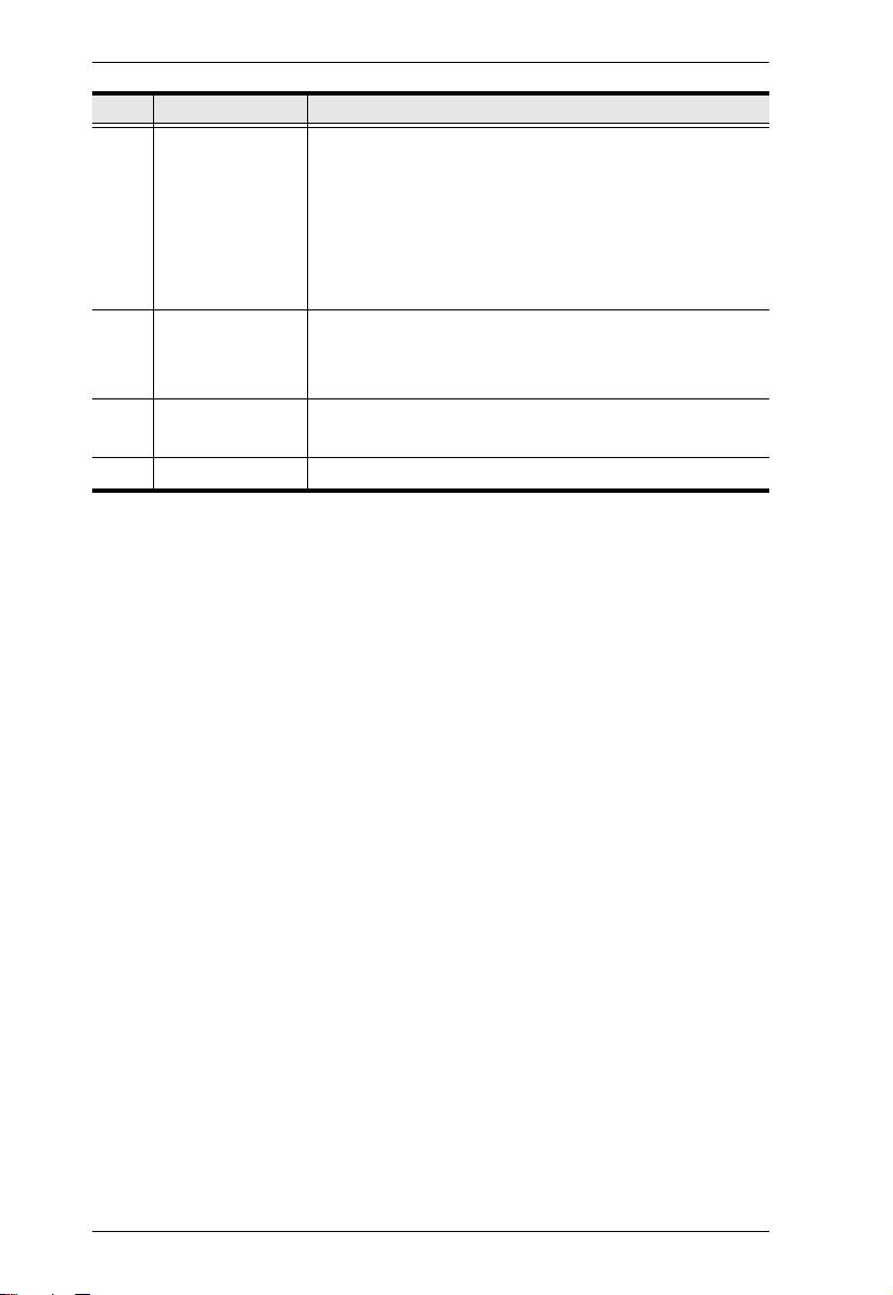
CM1164A Rear View
No. Component Description
1 Daisy Chain Control
In / Out ports
(DCC port)
2 Console Ports The cables from your USB keyboard, USB mouse, DVI
3KVM Ports
4 Power Socket / Power
Switch
5 Grounding Terminal The grounding wire (used to ground the unit) attaches
6 IR Receiver
(Extension)
Use these ports to connect to another CM1164A’s
DCC port to pass keyboard and mouse signals.
You can daisy chain up to four CM1164A units.
If the CM1164A is set up as a single station, you
can control the CM1164A by sending serial
commands through the DCC In port. For details,
see Chapter 6, RS-232 Operation.
console display, a USB peripheral, microphone and
speakers plug into this section.
Note: When both the front-panel and rear-panel audio
ports are used, the front panel takes priority.
The cables that link the CM1164A to your DVI-D
Single Link computers plug in here. Each group of
the DVI KVM ports is comprised of a microphone
jack, speaker jack, USB Type B port, and a DVI
Single Link connector.
You can upgrade the CM1164A’s firmware from a
computer connected to the USB KVM Port 1.
Plug in the power cord to the power socket and use
the switch to power on the CM1164A.
here.
This receives signals from the IR remote control
through an IR extension, which can be purchased
separately (see Optional Equipment, page 6).
9
Multi-View KVMP™ Switch User Manual
3
5
2
1
4
6
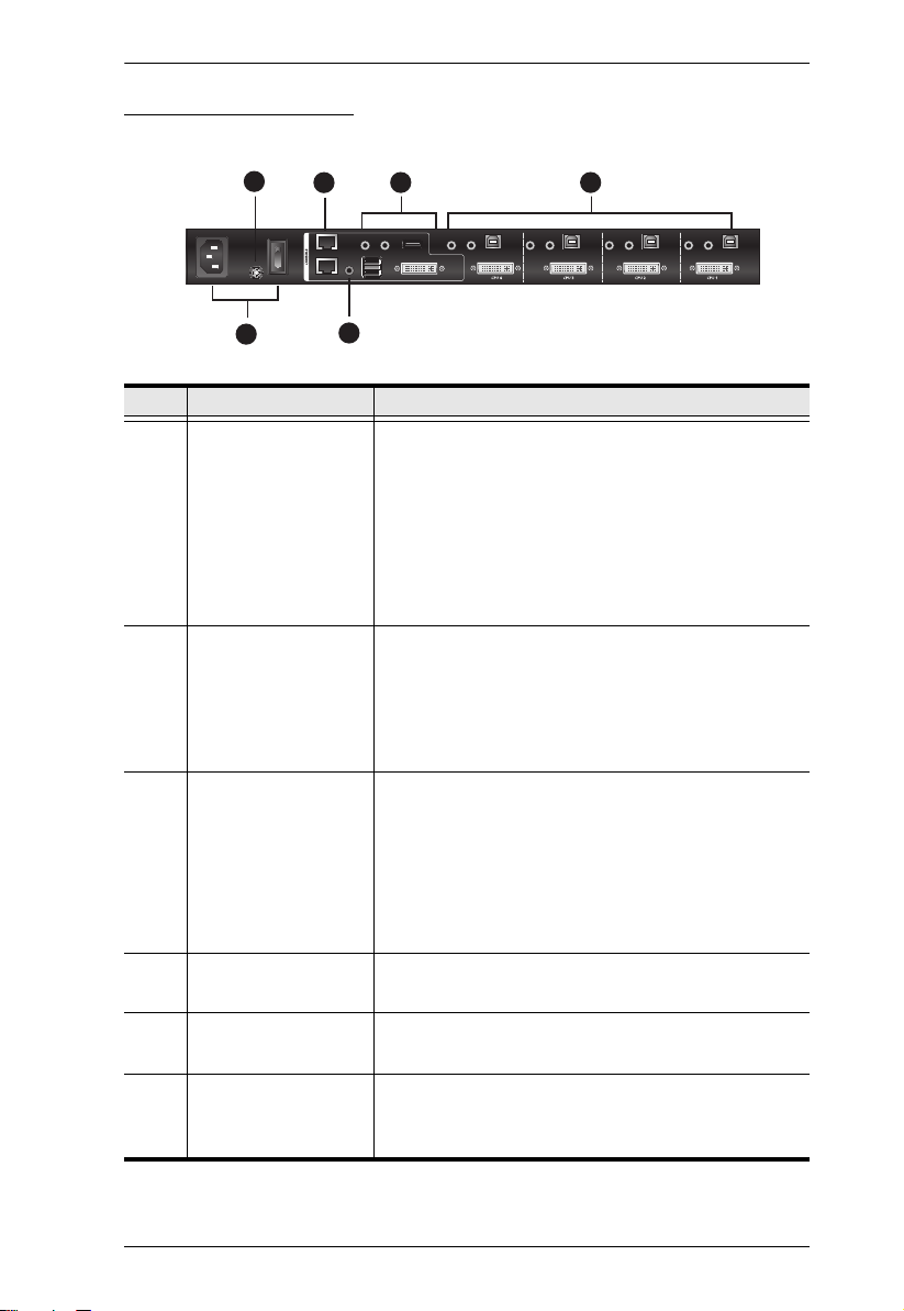
CM1284 Rear View
No. Component Description
1 Daisy Chain Control
In / Out ports
(DCC port)
2 Console Ports The cables from your USB keyboard, USB mouse,
3 KVM Ports
4 Power Socket and
Power Switch
5 Grounding Terminal The grounding wire (used to ground the unit) attaches
6IR Receiver
(Extension)
Use these ports to connect to another CM1284’s
DCC port to pass keyboard and mouse signals.
You can daisy chain up to four CM1284 units.
If the CM1284 is set up as a single station, you
can control the CM1284 by sending serial
commands through the DCC In port. For details,
see Chapter 6, RS-232 Operation.
HDMI console displays, a USB peripheral, microphone
and speakers plug into this section.
Note:
1. HDMI Port 1 supports multi-view modes; HDMI
Port 2 supports full-screen display only.
2. When both the front-panel and rear-panel audio
ports are used, the front panel takes priority.
The cables that link the CM1284 to your
computers plug in here. Each group of the KVM
ports is comprised of a microphone jack, speaker
jack, USB Type B port, and an HDMI connector.
You can upgrade the CM1284’s firmware from a
computer connected to the USB KVM Port 1.
Plug in the power cord to the power socket and use
the switch to power on the CM1284.
here.
This receives signals from the IR remote control
through an IR extension, which can be purchased
separately (see Optional Equipment, page 6).
10
Chapter 1. Introduction
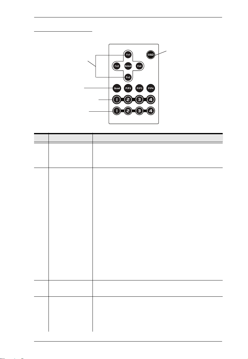
IR Remote Control
1
2
3
4
5
No. Component Description
1 OSD button Press this button to turn on or turn off the OSD Menu.
When the OSD Menu is enabled, press the OSD button to
go back to the previous menu/submenu.
2 Fn1 / Fn2 / Fn3 /
Fn4 Buttons and
Select Button
3 Display Mode
buttons
4KVM Port
Selection Buttons
1~4
Use these buttons to switch between Function modes (Fn1
to Fn4), and to cycle through the OSD Menu/selection.
See Preset Configuration, page 45 for details on how to
store function mode settings, which you can invoke for later
use.
The Fn1~Fn4 buttons are positioned to correspond to the
up / down / left / right direction.
When cycling through the menu options, press the Select
button to go the submenu.
If you want to change or adjust a selection/value, press
the Select button then the Fn1 (up) / Fn2 (left) / Fn3
(down) / Fn4 (right) buttons to go through all the
selections/values. Press the Select button again to
confirm a selection.
Select the Display Mode you want to view. See Display
Modes, page 35.
Press these buttons to switch ports (1~4).
In a cascade setup, press these buttons to switch the
console display to the corresponding secondary
TM
KVMP
Switch.
11

Multi-View KVMP™ Switch User Manual
No. Component Description
5 Station Selection
Buttons
If the Multi-View KVMP™ Switch is daisy chained to one or
several units (up to 4), press the button corresponding to
TM
the KVMP
Switch that you want to configure or operate.
12
Chapter 2
1. Important safety information regarding the placement of this
device is provided on page 115. Please review it before
proceeding.
2. To prevent damage to your installation from power surges or
static electricity. It is important that all connected devices are
properly grounded.
3. Make sure that the power to all devices connected to the
installation is turned off. You must unplug the power cords of
any computers that have the Keyboard Power On function.
Front
Back
Hardware Setup
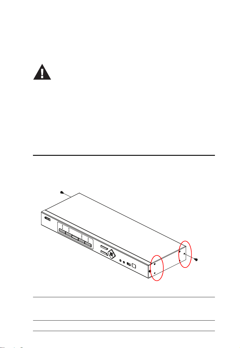
Rack Mounting
For convenience and flexibility, the Multi-View KVMP™ Switch can be
mounted on system racks. To rack mount a unit, do the following:
1. Remove the screws attached to the unit as shown in the diagram below:
Note: You can remove the screws on the front side panels or the back side
panels. The succeeding diagrams show the rack mounting steps for the
back panel.
13
Multi-View KVMP™ Switch User Manual
Phillips hex head
M3x6
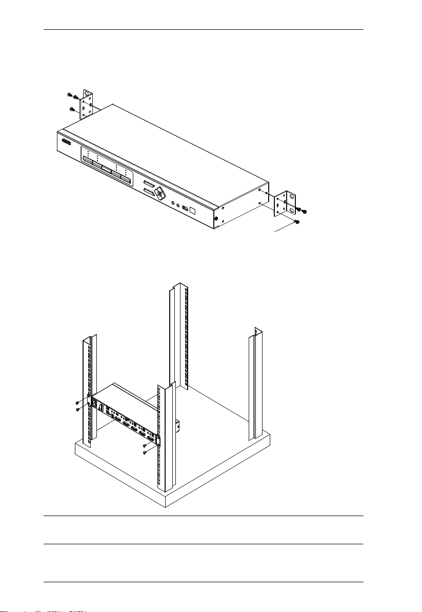
2. Using the screws provided in the Mounting Kit (not included with this
package), screw the mounting bracket into the side of the unit as show in
the diagram below:
Phillips hex head
M3x6
3. Screw the bracket into any convenient location on the rack.
Note: These screws are not provided in the Mounting Kit. We recommend t hat
you use M5 x 12 Phillips Type I cross, recessed type screws.
14

Chapter 2. Hardware Setup
Installation
CM1164A
You can install the CM1164A as a single station, daisy chain up to 4 CM1164A
units, or cascade up to 4 additional CM1164A units to a primary CM1164A.
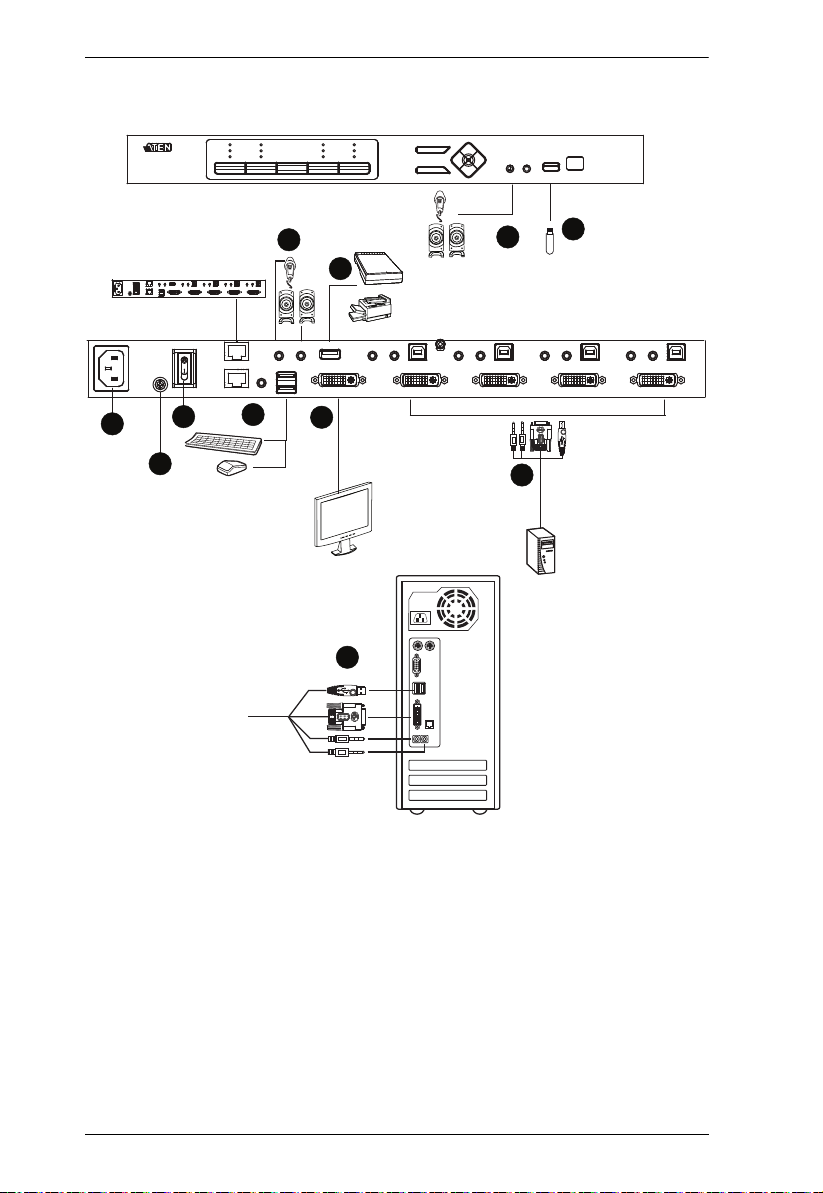
Single Station Installation
To set up a single CM1164A unit, refer to the installation diagram on page 16
(the numbers in the diagrams correspond to the steps below), and do the
following:
1. To prevent damages from power surges or static electricity, ground the
CM1164A by connecting one end of a grounding wire to the grounding
terminal, and the other end of the wire to a suitable grounded object.
Note:
The grounding wire is not included in the package. Please contact your
dealer for the appropriate cable.
Make sure the computers and devices that the CM1164A connects to
are also properly grounded.
2. Plug your USB keyboard and USB mouse into the USB Console Ports
located on the unit’s rear panel.
3. Plug your DVI display into the Console DVI Single Link Port located on
the unit’s rear panel.
4. To use separate microphone and speakers, plug them into the analog audio
ports on the unit’s front or rear panel. When both the front-panel and rearpanel audio ports are used, the front panel takes priority.
5. Using the USB DVI KVM cable, plug the DVI-D Single Link cable
connector and the accompanying USB and audio connectors to their
corresponding ports on the rear of the KVM switch.
6. At the other end of the cable, plug the DVI and USB cables into their
respective ports on the source computer.
7. Plug your USB peripherals into the Type A ports (one easy-access port is
located on the front for portable devices; the second is located on the rear).
8. Plug the power cord into the CM1164A power socket, and then plug the
other end of the power cord into an AC power source.
9. Power on the KVM switch, the display, and the computers/devices.
Note: The recommended power-on sequence is Port 1–Port 2–Port 3–Port
4.
15
Multi-View KVMP™ Switch User Manual
7
8
2
4
3
DVI
7
4
5
9
6
1
Single Station Installation Diagram
16

Chapter 2. Hardware Setup
Daisy Chaining
To display even more computers/video source devices, up to 3 additional
CM1164A units can be daisy chained from the original CM1164A. As many as
16 computers/video source devices can be controlled from a single console in
a complete daisy chain installation. Each CM1164A in a daisy chain requires
its own monitor as the video signals cannot be passed through to other units on
a daisy chain. For Daisy Chain cable length restriction, see the table below.
Daisy Chain Unit Number of Cable Each Cable Length (Max.)
2 Units 1 150 m
3 Units 2 150 m
4 Units 3 100 m
To set up a daisy chain installation, make sure that the power to all devices has
been turned off, and do the following:
1. Use a Cat 5 cable to connect the DCC Out port of the primary CM1164A
to the DCC In port of the secondary CM1164A unit(s) (first station out to
second station in, second station out to third station in, etc.).
2. Plug a DVI display into the Console DVI Port located on each unit’s rear
panel.
3. Cable up the computer and the switch according to the information
provided under Single Station Installation, page 15.
4. Repeat the above for any other switches you want to add to the chain (up
to three).
5. Power up the installation: plug in the power cord for the first station, then
power on each station on the installation in turn (second station, then third
station, etc.). After all the stations are up, power on the computers/video
source devices.
Note: Make sure the computers and devices that the CM1164A connects
to are also properly grounded.
6. Make sure the Expansion setting is set to Daisy Chain in the OSD Menu
(Advanced > Expansion).
17
Multi-View KVMP™ Switch User Manual
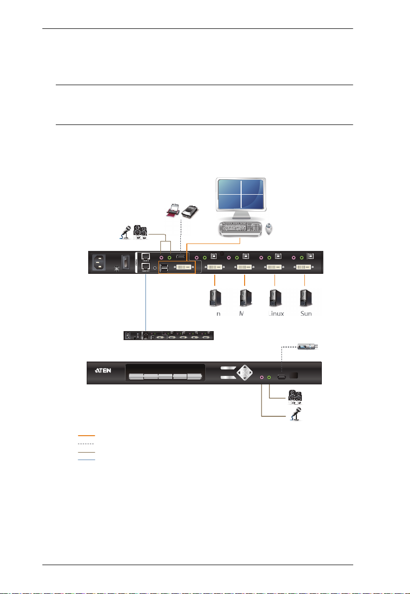
CM1164A (Rear)
CM1164A (Front)
1
2
3
4
SunLinuxMacWin
(Quad View)
Daisy-chain
USB
Audio
Cat 5e Cable
Video / Keyboard / Mouse
7. To switch to a computer in a daisy chain, select from the Control Station
setting in the OSD Menu (Advanced > Control Station). When switching
to a computer, only the keyboard and mouse signals are connected.
Note: The second, third, and forth units in a daisy chain will not be able to
use the IR remote for control. Only the first (primary) CM1164A
can use the IR remote for control.
Daisy Chain Installation Diagram
18

Chapter 2. Hardware Setup
Cascading
To centrally control up to 4 CM1164A units (16 computers/video sources),
cascade 4 additional CM1164A units to another CM1164A. As many as 16
computers/video source devices can be controlled from a single CM1164A
console in a complete cascade installation.
To set up a cascade installation, make sure that the power to all devices has
been turned off, and then do the following:
1. Connect the console ports of a secondary CM1164A to any of the DVI
KVM Ports on the primary CM1164A using the provided KVM cables.
2. To cascade another CM1164A, repeat step 1.
3. Connect the secondary CM1164A units with computers/video sources. For
detailed steps, see Single Station Installation, page 15.
4. Connect the primary CM1164A with a USB keyboard and a USB mouse.
5. Power up the installed CM1164A units. After all the stations are up, power
on the connected computers/video source devices.
Note: Make sure the computers and devices that the CM1164A connects
to are also properly grounded.
6. Change the installation setting from Daisy Chain to Cascade in the OSD
Menu (Advanced > Expansion).
7. Each secondary CM1164A unit is recognized as an input source (port 1 ~
4) to the primary CM1164A. To only display the sources of a particular
secondary CM1164A, use any of the following methods:
Press the corresponding front-panel port pushbutton
Press the corresponding port button on the IR remote control
19
Multi-View KVMP™ Switch User Manual
CM1164A Primary Unit
(4X4 multi-view)
USB
Audio
Cat 5e Cable
Video / Keyboard / Mouse
5
13
7
15
2
10
4
12
1
9
3
11
6
8
14
16
Secondary Unit
Secondary Unit Secondary Unit
Secondary Unit
Cascade Installation Diagram
20

Chapter 2. Hardware Setup
CM1284
You can install the CM1284 as a single station, daisy chain up to 4 CM1284
units, or cascade up to 4 additional CM1284 units to a primary CM1284.
Single Station Installation
To set up a single CM1284 unit, refer to the installation diagram on page 22
(the numbers in the diagrams correspond to the steps below), and do the
following:
1. Ground the CM1284 by connecting one end of a grounding wire to the
grounding terminal, and the other end of the wire to a suitable grounded
object.
Note:
The grounding wire is not included in the package. Please contact your
dealer for the appropriate cable.
Make sure the computers and devices that the CM1284 connects to are
also properly grounded.
2. Plug your USB keyboard and USB mouse into the USB Console Ports
located on the unit’s rear panel.
3. Plug your main HDMI display to Console HDMI Port 1 located on the
unit’s rear panel, and the second display to Console HDMI Port 2.
Note: The main display here refers to the display that you use to operate
and configure the Multi-View KVMP™ Switch and display multiview modes; the second display is limited to displaying a selected
source in full screen only.
4. To use separate microphone and speakers, plug them into the analog audio
ports on the unit’s front or the ones on the rear panel. When the audio ports
on both the front-panel and rear-panel are used, the front panel takes
priority.
5. Using the USB HDMI KVM cables, plug the HDMI connectors and the
accompanying USB and audio connectors to their corresponding ports on
the rear of the KVM switch.
6. At the other end of the USB HDMI KVM cables, plug the HDMI and USB
connectors into their respective ports on the source computer.
7. Plug your USB peripherals into the Type A ports (one easy-access port is
located on the front for portable devices; the second is located on the rear).
21

Multi-View KVMP™ Switch User Manual
HDMI Cable
1
2
3
4
QD2QD3QD4QD5
3
2
1
8
9
7
4
6
4
7
5
8. Plug the power cord into the CM1284’s power socket, and then plug the
other end of the power cord into an AC power source.
9. Power on the KVM switch, the displays, and the computers/devices.
Note: The recommended power-on sequence is Port 1–Port 2–Port 3–Port
4.
Single Station Installation Diagram
22

Chapter 2. Hardware Setup
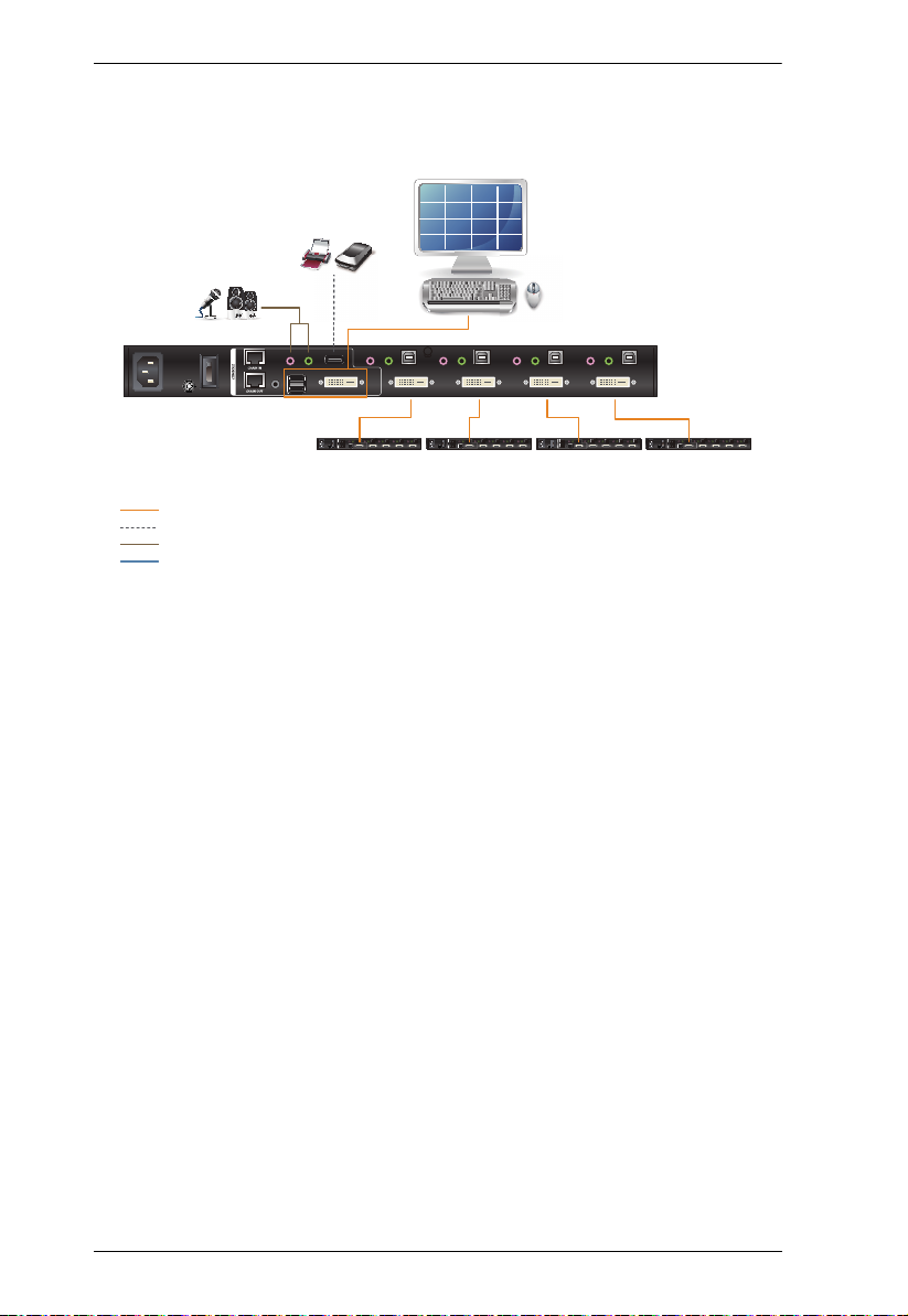
Daisy Chaining
To display even more computers/video source devices, up to 3 additional
CM1284 units can be daisy chained from the original CM1284. As many as 16
computers/video source devices can be controlled from a single console in a
complete daisy chain installation. Each CM1284 in a daisy chain requires its
own monitor as the video signals cannot be passed through to other units on a
daisy chain. For Daisy Chain cable length restriction, see the table below.
Daisy Chain Unit Number of Cable Each Cable Length (Max.)
2 Units 1 150 m
3 Units 2 150 m
4 Units 3 100 m
To set up a daisy chain installation, make sure that the power to all devices has
been turned off, and do the following:
1. Use a Cat 5 cable to connect the DCC Out port of the primary CM1284 to
the DCC In port of the secondary CM1284 unit(s) (first station out to
second station in, second station out to third station in, etc.).
2. Plug your main HDMI display to the Console HDMI Port 1 located on the
unit’s rear panel, and the second display to the Console HDMI Port 2.
Note: The main display here refers to the display that you use to operate
and configure the Multi-View KVMP™ Switch and display multiview modes; the second display is limited to displaying a selected
source in full screen only.
3. Cable up the computer and the switch according to the information
provided under Single Station Installation, page 21.
4. Repeat the above for any other switches you want to add to the chain (up
to three).
5. Power up the installation: plug in the power cord for the first station, then
power on each station on the installation in turn (second station, then third
station, etc.). After all the stations are up, power on the computers/video
source devices.
Note: Make sure the computers and devices that the CM1284 connects to
are also properly grounded.
6. Make sure the Expansion setting is set to Daisy Chain in the OSD Menu
(Advanced > Expansion).
23

Multi-View KVMP™ Switch User Manual
1
HDMI
Audio
USB
IR
Daisy Chain
CM1284 (Rear)
CM1284 (Front)
SunLinuxMacWindows
12
3
4
or
5
56
7
8
7. To switch to a computer in a daisy chain, select from the Control Station
setting in the OSD Menu (Advanced > Control Station). When switching
to a computer, only the keyboard and mouse signals are connected.
Note: The second, third, and forth units in a daisy chain will not be able to
use the IR remote for control. Only the first (primary) CM1284 can
use the IR remote for control.
Daisy Chain Installation Diagram
24

Chapter 2. Hardware Setup
Cascading
To centrally control up to 4 CM1284/CM1164A units (16 computers/video
sources) from a CM1284 unit, cascade 4 additional CM1284/CM1164A units
to the primary CM1284. As many as 16 computers/video source devices can be
controlled from a single CM1284 console in a complete cascade installation.
To set up a cascade installation, make sure that the power to all devices has
been turned off, and then do the following:
1. Connect the console ports of a secondary CM1284/CM1164A to any set of
the KVM Ports on the primary CM1284 using the provided KVM cables.
Note: Make sure to connect the Console HDMI Port 1 of the secondary
CM1284 instead of its Port 2 to the primary CM1284 to be able to
display multi-view modes.
2. To cascade another CM1284, repeat step 1.
3. Connect the secondary CM1284/CM1164A units with computers/video
sources. For detailed steps, see Single Station Installation, page 21.
4. Connect the primary CM1284 with a USB keyboard and a USB mouse.
5. Power up the installed CM1284/CM1164A units. After all the stations are
up, power on the connected computers/video source devices.
Note: Make sure the computers and devices that the CM1284/CM1164A
connects to are also properly grounded.
6. Change the installation setting from Daisy Chain to Cascade in the OSD
Menu (Advanced > Expansion).
7. Each secondary CM1284/CM1164A unit is recognized as an input source
(port 1 ~ 4) to the primary CM1284. To only display the sources of a
particular secondary CM1284/CM1164A, use any of the following
methods:
Press the corresponding front-panel port pushbutton
Press the corresponding port button on the IR remote control
25

Multi-View KVMP™ Switch User Manual
CM1284 (Rear)
(4X4 multi-view)
USB
Audio
Video / Keyboard / Mouse
5
13
7
15
2
10
4
12
1
9
3
11
6
8
14
16
13
9
5
1
Cascade Installation Diagram
26

Chapter 3
This computer is connected to Port 1
This computer is named PC 1
Click to extend the window to full screen
Basic Operation
Overview
This chapter explains the basic components used to switch and display
computers connected to the Multi-View KVMP™ Switch.
Identifying the Source Device
You can identify the source connected to the Multi-View KVMP™ Switch
from the channel information at the top-left corner in the screen:
Note: To hide this information, disable the Channel Info setting (Display >
Channel Info) from the OSD Menu.
27

Multi-View KVMP™ Switch User Manual
Port ID number: This number is assigned according to the port that the
computer is connected to on the rear of the KVM Switch. For example, a
computer connected to port 1 is assigned port ID 1.
Note: In a cascade setup, a port ID number of “1-3” indicates that the video
source comes from the third port of the secondary Multi-View
KVMP™ Switch connected to port 1 of the primary Multi-View
KVMP™ Switch.
Device name: By default, the computer connected to port 1 is named PC 1,
the computer connected to port 2 is named PC 2, and so forth. To change
the device name, go to System Settings > Port Configuration.
28

Chapter 3. Basic Operation
1
2
3
4
MODE
LED
KVM Port Selection
Switching
The Multi-View KVMP™ Switch supports group switching and independent
switching:
Group switching: switches to the KVM (keyboard, video, mouse), audio,
and USB sources of one computer.
Independent switching: switches to KVM (keyboard, video, mouse),
stereo audio, and USB sources independently, on different computers. This
allows you to work on one computer (KVM), access the audio on another
(stereo audio), and connect to peripheral devices on a third (USB).
Note: By default, the CM1284’s Display 2 shows a video that is shown on
Display 1, or of the focused video on Display 1 when Display 1 is in
a multi-view mode. To have Display 2 show video of a particular
computer regardless of the focused video on Display 1, configure
the Display B Status setting in the OSD.
Front Panel Pushbuttons
Use the KVM Port Selection and Mode pushbuttons located on the front panel
to switch KVM, audio, and/or USB focus. The selected devices are indicated
with LEDs on the front panel. For more information about LED indicators, see
LED Display, page 30.
To switch KVM, stereo audio, and USB focus to a computer, press the
KVM Port Selection pushbutton that corresponds to the computer you
want to access.
To switch KVM access to a computer, press Mode 2 times, and then press
the KVM Port Selection pushbutton that corresponds to the computer.
29

Multi-View KVMP™ Switch User Manual
To switch stereo audio access to a computer, press Mode 3 times, and then
press the KVM Port Selection pushbutton that corresponds to the
computer.
To switch USB access to a computer, press Mode 4 times, and then press
the KVM Port Selection pushbutton that corresponds to the computer.
Press KVM Port Selection pushbuttons 1 and 2 for 2 seconds to start
Auto Scan Mode. To stop auto scan, press and release either port selection
pushbutton.
LED Display
The front panel has three LEDs that represent the KVM, Audio and USB
source. The LEDs light green or orange depending on which source is being
accessed on what computer, as explained in the table.
LED Indication
Icon KVM
Audio
Lights BRIGHT ORANGE to indicate KVM is selected.
Flashes ORANGE to indicate that the computer is being
accessed in Auto Scan Mode.
All flash ORANGE to indicate a firmware upgrade has
been invoked.
The corresponding port LED of the USB keyboard/
mouse flashes when Keyboard Bypass is enabled.
Lights a faint ORANGE to indicate that a computer is
powered on.
Lights BRIGHT GREEN to indicate Audio is selected.
Flashes GREEN to indicate that Audio is selected on a
computer in a Daisy Chain setup.
30
USB Link
Lights BRIGHT GREEN to indicate USB is selected.
Flashes GREEN to indicate that USB Link is selected on
a computer in a Daisy Chain setup.

Chapter 3. Basic Operation
Hotkey Switching
You can switch to a computer using hotkeys from the keyboard.
To switch to computer 1, do the following:
1. Press and hold down [Num Lock].
2. Press and release [-].
3. Release [Num Lock].
4. Press [1].
5. Press [Enter].
Repeat the steps using Port ID (1, 2, 3, 4) in step 4 to switch to the computer
connected to that port. For more hotkeys, see Hotkey Operation, page 47.
IR Remote Switching
You can switch to a computer with the IR remote control. Point the remote at
the Multi-View KVMP™ Switch and press the Port Selection button of the
computer you want to access.
31

Multi-View KVMP™ Switch User Manual
OSD Switching
You can switch to a computer by accessing the Quick Access Toolbar with the
console mouse.
To switch computers with the OSD, do the following:
1. Move the cursor to the top of the OSD to display the Quick Access Bar.
2. From the Quick Access Toolbar, click
message “Press
32
to exit edit mode” appears.
to activate the editor mode. The

Chapter 3. Basic Operation
3. Click the port number at the top-left corner to open drop-down list, and
then select a computer: 1, 2, 3, or 4. The display is immediately switched
to the selected computer.
4. When you finish configuring, click
to end the editor mode.
Boundless Switching
Boundless Switching allows the Multi-View KVMP™ Switch to switch
computers by sliding the mouse cursor across the screen borders. The mouse
cursor can be moved up, down, left, or right– off one screen and onto another
to switch keyboard/mouse control to the adjacent computer. The audio and
USB hub focus is also switched to the new computer. The mouse cursor can
also move across displays even when they are daisy-chained.
Before using the Boundless Switching, the users must turn off mouse
acceleration in the operation system and configure:
The daisy-chained monitors layout via hotkey page 52, OSD page 63, and
RS-232 page 77 for more information.
A Window Frame appears on the Multi-View display with a computer that it
currently has the focus. This is a Boundless Switching Focus, to indicate which
computer the user is working on. This Window Frame can be disabled and
adjusted via the hotkey, and OSD. For more information, see page 52 for
hotkey and page 62 for OSD.
Multiview Monitor Layout Rule
The Multiview Monitor Layout Rule is a setup restriction for the daisy-chain
boundless switching. Please follow the multiview monitor layout rule below to
configure your daisy-chain installation.
Note: Monitor 1 refers to the multiview monitor connected to station 1;
Monitor 2 refers to the multiview monitor connected to station 2;
Monitor 3 refers to the multiview monitor connected to station 3; and
Monitor 4 refers to the multiview monitor connected to station 4
respectively.
33

Multi-View KVMP™ Switch User Manual
12
3
4
56
7
8
910
11
12
13 14
15
16
Monitor
1
Monitor
2
Monitor
3
Monitor
4
12
3
4
56
7
8
910
11
12
13 14
15
16
Monitor
1
Monitor
2
Monitor
3
Monitor
4
12
3
4
56
7
8
910
11
12
13 14
15
16
Monitor
1
Monitor
2
Monitor
3
Monitor
4
Tier (Chain Vert) Layout
Row (Chain Horz) Layout
Quarter (Chain 2 x 2) Layout
34

Chapter 3. Basic Operation
Display Modes
You can view multiple computers connected to the Multi-View KVMP™
Switch on the same screen, in different layout by setting the display mode. This
section introduces you to different display modes, and ways of switching to
them.
Note: In a CM1284 system, Display 2 supports full-screen mode only.
Full Screen
A full-screen view displays one computer in full extension.
Method Action Description
Front Panel Press a KVM Port Selection
IR Remote
Control
Mouse
Wheel
Pushbutton.
Press a KVM Port Selection
Pushbutton.
In any PiP mode, move the cursor to the
window you wish to extend, and doubleclick the mouse wheel.
Note: This function is disabled by default.
To use this function, enable the
Advanced > Mouse Wheel Switching
function from the OSD Menu.
N/A
35

Multi-View KVMP™ Switch User Manual
Method Action Description
Quick Access
Toolbar
Hotkey Switch to a particular port to display the
Move the mouse to the top center of the
OSD to display the Quick Access Toolbar,
and then select from the Quick Access
Toolbar.
Note: Hardware Cursor Mode must be
enabled, see The OSD Menu, page 59.
computer in full screen. See The Hotkey
Setting Mode, page 48 for hotkey
instructions.
OSD Menu
In the OSD, click from the Quick
Access Toolbar, go to Display >
Multiview Mode, and then select Single.
Note: You may need a password to
access the OSD Menu. For details, see
Password Protection, page 60.
36

Chapter 3. Basic Operation
Quad View
A quad view displays four computers on the monitor in equal sized windows.
Method Action Description
Front Panel Press Select to cycle through display
modes.
IR Remote
Control
Quick Access
Toolbar
Hotkey Enter the illustrated hotkeys. See The
OSD Menu
Press the Quad button.
Move the mouse to the top center of the
OSD to display the Quick Access Toolbar,
and then select from the Quick Access
Toolbar.
Note: Hardware Cursor Mode must be
enabled, see The OSD Menu, page 59.
Hotkey Setting Mode, page 48 for hotkey
instructions.
In the OSD, click from the Quick
Access Toolbar, go to Display >
Multiview Mode, and then select Quad.
Note: You may need a password to
access the OSD Menu. For details, see
Password Protection, page 60.
37

Multi-View KVMP™ Switch User Manual
Picture in Picture - Dual
A dual PiP view shows 2 computers on the monitor with one as the main
display, and the other overlapping the main display in an inset window.
Method Action Description
Front Panel Press Select to cycle through display
modes.
IR Remote
Control
Quick Access
Toolbar
Hotkey Enter the illustrated hotkeys. See The
OSD Menu
Press the PiP2 button.
Move the mouse to the top center of
the OSD to display the Quick Access
Toolbar, and then select from the Quick
Access Toolbar.
Note: Hardware Cursor Mode must be
enabled, see The OSD Menu, page 59.
Hotkey Setting Mode, page 48 for
hotkey instructions.
In the OSD, click from the Quick
Access Toolbar, go to Display >
Multiview Mode, and then select PiP2.
Note: You may need a password to
access the OSD Menu. For details, see
Password Protection, page 60.
38

Chapter 3. Basic Operation
Picture in Picture - Triple
A triple PiP view has 3 computers on the monitor with one computer as the
main display and the other two overlapping the main display in inset windows.
Method Action Description
Front Panel Press Select to cycle through display
modes.
IR Remote
Control
Quick Access
Toolbar
Hotkey Enter the illustrated hotkeys. See The
OSD Menu
Press the PiP3 button.
Move the mouse to the top center of the
OSD to display the Quick Access Toolbar,
and then select from the Quick Access
Toolbar.
Note: Hardware Cursor Mode must be
enabled, see The OSD Menu, page 59.
Hotkey Setting Mode, page 48 for hotkey
instructions.
In the OSD, click from the Quick
Access Toolbar, go to Display >
Multiview Mode, and then select PiP3.
Note: You may need a password to
access the OSD Menu. For details, see
Password Protection, page 60.
39

Multi-View KVMP™ Switch User Manual
Picture in Picture - Quad
A quad PiP view has 4 computers on the monitor with one computer as the
main display and the other three overlapping the main display in inset
windows.
Method Action Description
Front Panel Press Select to cycle through display
modes.
IR Remote
Control
Quick Access
Toolbar
Hotkey See The Hotkey Setting Mode, page 48
OSD Menu
Press the Pi4 button.
Move the mouse to the top center of
the OSD to display the Quick Access
Toolbar, and then select from the Quick
Access Toolbar.
Note: Hardware Cursor Mode must be
enabled, see The OSD Menu, page 59.
for hotkey instructions.
In the OSD, click from the Quick
Access Toolbar, go to Display >
Multiview Mode, and then select PiP4.
Note: You may need a password to
access the OSD Menu. For details, see
Password Protection, page 60.
40

Chapter 3. Basic Operation
Picture on Picture
A picture-on-picture (PoP) view shows 4 computers in separate windows on
the monitor. In editor mode, you can use the console mouse to resize and
re-position each window on the screen.
Method Action Description
Front Panel Press Select to cycle through
display modes.
Quick Access
Toolbar
Hotkey Enter the illustrated hotkeys.
OSD Menu
Move the mouse to the top center of
the OSD to display the Quick
Access Toolbar, and then select
from the Quick Access Toolbar.
Note: Hardware Cursor Mode must
be enabled, see The OSD Menu,
page 59.
See The Hotkey Setting Mode,
page 48 for hotkey instructions.
In the OSD, click from the
Quick Access Toolbar, go to
Display > Multiview Mode, and
then select PoP.
Note: You may need a password to
access the OSD Menu. For details,
see Password Protection, page 60.
41

Multi-View KVMP™ Switch User Manual
Picture by Picture - Dual
The picture-by-picture (dual) view displays 2 computers side by side on the
monitor.
Method Action Description
Front Panel Press Select to cycle through
display modes.
Quick Access
Toolbar
Hotkey Enter the illustrated hotkeys.
OSD Menu
Move the mouse to the top center
of the OSD to display the Quick
Access Toolbar, and then select
from the Quick Access Toolbar.
Note: Hardware Cursor Mode
must be enabled, see The OSD
Menu, page 59.
See The Hotkey Setting Mode,
page 48 for hotkey instructions.
In the OSD, click from the
Quick Access Toolbar, go to
Display > Multiview Mode, and
then select PbP2.
Note: You may need a password
to access the OSD Menu. For
details, see Password Protection,
page 60.
42

Chapter 3. Basic Operation
Picture by Picture - Triple
The picture-by-picture (triple) view displays 3 computers side by side on the
monitor.
Method Action Description
Front Panel Press Select to cycle through
display modes.
Quick Access
Toolbar
Hotkey Enter the illustrated hotkeys.
OSD Menu
Move the mouse to the top center
of the OSD to display the Quick
Access Toolbar, and then select
from the Quick Access Toolbar.
Note: Hardware Cursor Mode must
be enabled, see The OSD Menu,
page 59.
See The Hotkey Setting Mode,
page 48 for hotkey instructions.
In the OSD, click from the
Quick Access Toolbar, go to
Display > Multiview Mode, and
then select PbP3.
Note: You may need a password to
access the OSD Menu. For details,
see Password Protection, page 60.
43

Multi-View KVMP™ Switch User Manual
Picture by Picture - Quad
The picture-by-picture (quad) view displays 4 computers side by side on the
monitor.
Method Action Description
Front Panel Press Select to cycle through
display modes.
Quick Access
Toolbar
Hotkey Enter the illustrated hotkeys.
OSD Menu
Move the mouse to the top center of
the OSD to display the Quick
Access Toolbar, and then select
from the Quick Access Toolbar.
Note: Hardware Cursor Mode must
be enabled, see The OSD Menu,
page 59.
See The Hotkey Setting Mode,
page 48 for hotkey instructions.
In the OSD, click from the
Quick Access Toolbar, go to
Display > Multiview Mode, and
then select PbP4.
Note: You may need a password to
access the OSD Menu. For details,
see Password Protection, page 60.
44

Chapter 3. Basic Operation
Preset Configuration
You can save up to 4 sets of configuration, including the display mode, source
assignment, division sizes, division locations, and KVM/Audio/USB focus
status to easily toggle between different display configurations.
To save a configuration, follow the steps below.
1. Configure the display settings as required.
2. Move the console mouse to the top of the screen. The Quick Access
Toolbar appears.
3. Click and select a preset (Fn) to save the current configuration.
4. To apply a preset configuration, use any of the following methods.
Method Action Description
Front Panel
Pushbutton
IR Remote
Control
Press the Fn1, Fn2, Fn3, or Fn4
pushbutton.
Press the Fn1, Fn2, Fn3, or Fn4
button.
45

Multi-View KVMP™ Switch User Manual
Method Action Description
Quick Access
Toolbar
Move mouse to top center of the
OSD and then select from the Quick
Access Toolbar.
Note: Hardware Cursor Mode must
be enabled, see
page 59.
Hotkey Enter the illustrated hotkeys.
Hotkey Setting Mode
The OSD Menu
, page 48 for
,
See The
hotkey instructions.
3-button wheel
mouse
Use the mouse wheel to toggle
between different Fn settings.
N/A
46

Chapter 4
Hotkey Operation
The Multi-View KVMP™ Switch provides easy-to-use hotkeys to control and
configure your KVM installation from the keyboard.
Open the OSD Menu
To activate the OSD using your keyboard, tap the Scroll Lock key twice:
[Scroll Lock] [Scroll Lock]
You can close the OSD Menu by pressing [Esc] or Spacebar.
[Esc] returns to the previous page.
Spacebar immediately exits the OSD.
Note: The hotkey to activate the OSD can be changed to the Ctrl key. See The
OSD Menu, page 59 for details.
47

Multi-View KVMP™ Switch User Manual
The Hotkey Setting Mode
You can operate and configure the Multi-View KVMP™ Switch with hotkeys
when the Hotkey Setting Mode (HSM) is enabled. To use hotkeys, do the
following:
1. Invoke the Hotkey Setting Mode.
a) Press and hold down [Num Lock].
b) Press and release [-].
c) Release [Num Lock]. The HSM is activated. The Caps Lock, and
Scroll Lock LEDs flash in succession to indicate that the HSM is in
effect.
Note:
When the HSM is activated, ordinary keyboard and mouse functions
are suspended – only hotkey keystrokes can be used.
To change the keys for invoking the HSM, see The OSD Menu,
page 59 for details.
2. Type the hotkeys to execute actions.
For a complete list of hotkeys, see Hotkeys List, page 49.
3. To disable Auto Scan, press [Esc] or [Space Bar].
48

Hotkeys List
Hotkey Function
Port
Switching
[Enter] Switch the focus of all the devices, including KVM, USB
[Port ID] [Device]
[Enter]
[Station ID] [Port
ID] [Device]
[Enter]
Chapter 4. Hotkey Operation
hub and audio to the next computer.
(Port 1 to Port 2, Port 2 to Port 3, Port 3 to Port 4, and
Port 4 to Port 1.)
Switch the focus of the KVM, USB, and/or audio
(microphone and speakers) to the specified computer in
a single station setup.
[Port ID] specifies the target computer:
When [Port ID] is omitted, the CM1164A/CM1284
switches to the specified device on the next
computer device.
[Port ID] = 1, 2, 3, or 4
[Device] specifies the focused device:
[Device] = K or omitted (KVM)
[Device] = U (USB hub)
[Device] = S (Microphone and speakers)
To switch two or all three devices to a computer at the
same time, type the [Device] keys. For example, [Port
ID] [K] [U] will switch the KVM and USB hub focus to the
specified port.
Switch the focus of the KVM, USB, and/or audio to the
specified computer in a daisy-chained setup.
[Station ID] and [Port ID] specify the target computer:
When [Station ID] is omitted, the CM1164A/CM1284
targets the computer at the next station.
[Station ID] = 1, 2, 3, or 4
[Port ID] = 1, 2, 3, or 4
[Device] sets the focused device:
[Device] = K or omitted (KVM)
[Device] = U (USB hub)
[Device] = S (Microphone and speakers)
To switch two or all three devices to a computer at the
same time, type the [Device] keys. For example,
[Station ID] [Port ID] [K] [U] will switch the KVM and
USB hub focus to the specified port.
49

Multi-View KVMP™ Switch User Manual
Hotkey Function
Display
Settings
[A] [n] [Enter] Start Auto Scan with which the KVM focus cycles from
port to port at the specified interval (n = 5, 10, 15, 30,
60, 90 seconds). The default interval is 5 seconds.
See Auto Scanning, page 53 for more information.
[J] [n] [Enter] Set the video content for Monitor 2. This function is only
supported on the CM1284. [n] specifies the source of
the displayed video.
n is omitted (Displays the content of the focused
window on Monitor 1)
n = 1 (Always displays the video from port 1)
n = 2 (Always displays the video from port 2)
n = 3 (Always displays the video from port 3)
n = 4 (Always displays the video from port 4)
[P] [n] [Enter] Switch to the specified (n) display mode. For more
information on display modes, See Display Modes,
page 35.
n = 0 (PoP)
n = 1 (Quad view)
n = 2 (PiP dual view)
n = 3 (PiP triple view)
n = 4 (PiP quad view)
n = 5 (PbP dual view)
n = 6 (PbP triple view)
n = 7 (PbP quad view)
50

General
Settings
Chapter 4. Hotkey Operation
Hotkey Function
[V] [n] [Enter] Configure the EDID (n) for the KVM Switch.
n = 1 (Uses the EDID of the monitor connected to
Port 1.)
n = 2 (Uses the EDID of the monitor connected to
Port 2. This setting is supported by CM1284 only.)
n = 3 (Sets the EDID to Remix mode, with which the
Multi-View KVMP™ Switch uses the optimum
EDID.)
n = 4 (Sets the EDID to FHD which is 1920 x 1080
@60Hz.)
n = 5 (Sets the EDID to 4K UHD which is 3840 x
2160 @30Hz. This setting is supported by CM1284
only.)
n = 6 (Sets the EDID to 4K DCI which is 4096 x
2160 @30Hz. This setting is supported by CM1284
only.)
[F1] [Enter] Enables the operating system to SPC.
[F2] [Enter] Enables Mac keyboard emulation.
[F3] [Enter] Enables Sun keyboard emulation.
[F4] [Enter] List the current settings of the Multi-View KVMP™
[F5] [Enter] Reset USB devices. If any USB devices lose focus or
[F6] [nn] [Enter] [n] sets the keyboard language:
[F10] [Enter] Enables Windows keyboard emulation. This is the
[B] [Enter] Enable or disable the beeper.
[E] [Enter] Enable or disable Power On Detection with which the
Switch. To use this function, open a text editor or word
processor, and place the cursor in the page window
before invoking the HSM and enter the hotkey.
connectivity, a USB reset may solve the issue.
n = 08 (French)
n = 09 (German)
n = 15 (Japanese)
n = 33 (English)
default setting.
Multi-View KVMP™ Switch switches to the next
powered-on computer when a computer that has KVM
focus is powered off.
51

Multi-View KVMP™ Switch User Manual
Hotkey Function
[F] [n] [Enter] Apply the specified Fn preset configurations (n = 1, 2, 3,
or 4). For more information on Fn preset configurations,
see Preset Configuration, page 45.
[I] [n] [Enter] Sets the layout for daisy-chained boundless switching.
[H] [Enter] Enable or disable the Hardware Cursor Mode.
[L] [Enter] Lock or unlock the front-panel pushbuttons.
[M] [Enter] Enable or disable mouse emulation.
[N] [Enter] Enable or disable keyboard emulation.
[O] [Enter] Disable the boundless switching focus.
[O] [n] [Enter] Enable the boundless switching focus, the [n] sets the
[u][p][g][r][a][d][e]
[Enter]
[W] [Enter] Enable or disable port switching using the console
For more information, see Multiview Monitor Layout
Rule, page 33.
n = 1, sets a row (Chain Horz) layout for daisychained monitors
n = 2, sets a quarter (Chain 2x2) layout for daisychained monitors
n = 3, sets a tier (Chain Vert) layout for daisychained monitors
duration for the boundless switching focus.
n = 0, boundless switching focus lights and stays on
n = 1, boundless switching focus lights on for 3
seconds
n = 2, boundless switching focus lights on for 5
seconds
n = 3, boundless switching focus lights on for 10
seconds
Initiate a firmware upgrade.
mouse.
52

Chapter 4. Hotkey Operation
Auto Scanning
The Auto Scan feature automatically cycles the KVM focus through the
computer ports at regular intervals. This allows you to monitor the computer
activity without having to switch from port to port manually. Although the
video focus switches from port to port, the keyboard, mouse, and USB focus
do not switch. They stay with the port they were on when Auto Scanning
started.
While Auto Scan Mode is in effect, ordinary keyboard and mouse functions are
suspended – only Auto Scan Mode keystrokes and mouse clicks can be input.
You must exit Auto Scan Mode in order to regain normal control of the
console.
Auto Scanning - Display Modes
Auto scan can be invoked with Full Screen, PiP Dual, PiP Triple, PbP Dual,
and PbP Triple modes. When you start auto scan with PiP Dual or PiP Triple
one of the secondary windows (channels) is used to auto scan two or three
computers.
Auto Scan mode does not work with the Quad View, PiP Quad, or PoP mode
as these modes already display all computers on the screen. (see Display
Modes, page 35).
53

Multi-View KVMP™ Switch User Manual
This Page Intentionally Left Blank
54

Chapter 5
OSD Operation
Overview
The Multi-View KVMP™ Switch can be operated and configured via the
following OSD components:
Quick Access Toolbar: This toolbar provides quick access for changing
the display mode, saving display templates, and customizing division
sizes. For details, see The Quick Access Toolbar, page 55.
OSD Menu: This contains controls for all system settings. For details, see
The OSD Menu, page 59.
The Quick Access Toolbar
You can use the Quick Access Toolbar to conveniently switch display modes,
customize window size and location via the editor mode, and apply and save
display templates.
55

Multi-View KVMP™ Switch User Manual
To display the Quick Access Toolbar, move the console mouse to the top of the
screen. The Quick Access Toolbar provides the following controls:
: Click this icon to enable the editor mode to allow you to assign source
to a particular channel and resize inset windows.
: Click this icon to save the current display configuration to a display
template.
: Click this icon to open the OSD Menu. For details, see The OSD Menu,
page 59.
: Click a Function icon to apply the selected display template.
: Click an icon to apply the display mode.
Note:
Make sure to enable Hardware Cursor and Mouse Emulation to access the
Quick Access Toolbar using the console mouse.
To change the display position, go to Display > Toolbar Position in the
OSD Menu.
56

Chapter 5. OSD Operation
The Editor Mode
Use the editor mode to customize the source display. You can resize windows,
change the display source, or relocate windows. To enable the editor mode,
follow the steps below.
1. Make sure the following functions are enabled to allow console mouse to
operate. For details, see The OSD Menu, page 59.
Hardware Cursor
Mouse Emulation
2. Move the console mouse to the top of the screen to display the Quick
Access Toolbar.
3. Click from the Quick Access Tool. A Press ““ to exit edit mode
message appears to indicate that the editor mode is enabled.
57

Multi-View KVMP™ Switch User Manual
4. Configure and adjust the display as required. You can do the following
when the editor mode is enabled:
Function Action
Change the display mode
Apply a preset configuration Click an Fn icon from the Quick Access Toolbar. For
Swap locations of video
sources in quad mode
Resize windows Click on a window, move the cursor to a corner of
Relocate windows Click and hold on a window to drag it to a desired
Set windows to the front or
the back
Reset
Click a display mode from the Quick Access
Toolbar.
Click to display the window in full screen.
more information, see Preset Configuration,
page 45.
Click the port number at the top left corner and
select a port.
Note: Under 4K resolution, to use this function in a
Quad view, make sure port 1 and 2, port 3 and 4 are
next to each other.
the window, and drag the corner to resize the
window.
Note: Under 4K resolution, red zones appear to
indicate the resized window exceeds the restricted
limits.
location on the screen.
Note: Under 4K resolution, red zones appear to
indicate restricted areas for the dragged window.
When two windows overlap, you can configure
which one appears on top of the other. To bring a
window on top of the other, click the window, and
then click . Click to send the selected
window to the back.
Click to reset all the port location and size back
to default settings.
Note: When the editor mode is enabled, the OSD Menu will not be
accessible and the hotkeys functionality will be disabled.
5. When you finish configuring, click
58
to quit the editor mode.

Chapter 5. OSD Operation
The OSD Menu
The OSD Menu contains all the display settings and system settings for the
Multi-View KVMP™ Switch. To access the OSD Menu, use any of the
following methods:
Press the OSD pushbutton on the front panel.
Press the OSD button on the IR remote control
Tap [Scroll Lock] twice on the console keyboard
Move the console mouse to the top center of the OSD to display the Quick
Access Toolbar, and then click .
59

Multi-View KVMP™ Switch User Manual
Password Protection
By default, the Multi-View KVMP™ Switch’s OSD Menu is protected by
password and is locked if the OSD Menu has not been operated for 30 seconds.
This is to secure the advanced settings, the OSD Menu, from general operations
using the Quick Access Toolbar, including:
Change the display mode
Switch sources
Resize and relocate the windows in any multiview mode
Change the display order of the PoP mode
Save configurations
Apply preset configurations
Swap ports
Re-assign channel position in any multiview mode
Note:
To disable password protection or to change the password, go to Password
> Password Protection in the OSD Menu.
To configure how long the Multi-View KVMP™ Switch logs out from the
OSD Menu, go to General > Logout Timeout in the OSD Menu.
60

Chapter 5. OSD Operation
System Settings
The following settings are available in the OSD Menu. Default settings are
indicated in bold.
Setting Options Description
General
OSD Language English / Chinese TW /
Chinese CN /
Japanese, Korean /
French / German /
Italian / Russian
Pushbutton Lock Enable / Disable Locks or unlocks the Multi-View
Logout Timeout Never / 10s / 30s / 60s
/ 5 mins / 10 mins
Active Beeper Enable / Disable
Display B Status Follow A / Port 1 / Port
2 / Port 3 / Port 4
Keyboard Language English / German /
Japanese / French
Hardware Cursor Enable / Disable /
Transparency
Sets the language for the OSD Menu.
KVMP™ Switch’s panel pushbuttons.
Sets how long the Multi-View KVMP™
Switch waits after the last input before
automatically logging out from the OSD
Menu.
Enable this function for Multi-View
KVMP™ Switch to sound a beep to
indicate and confirm user configuration.
This setting is supported by the
CM1284 only. Sets the video source of
the display connected to the HDMI
Console Port 2 on the CM1284.
Sets the language of the console
keyboard. For these options to be
available, make sure to enable
Keyboard Emulation in the OSD Menu.
Enable this function to allow the use of
console mouse to customize division
sizes, shift between divisions, and
display the Quick Access Toolbar. The
Channel Editor provides a way to
change display modes and other
settings with the mouse and an onscreen control panel.
Note: Mouse Emulation must be
enabled for Hardware Cursor Mode to
work (see Mouse Emulation, page 62).
61

Multi-View KVMP™ Switch User Manual
Setting Options Description
HSM [Num][-] / [Ctrl][F12] Defines the hotkey combination for
enabling the Hotkey Setting Mode
(HSM).
Menu Hotkey Scroll*2 / Ctrl*2 Sets the hotkey combination for
opening the menu.
Display
Channel Info Enable / Disable Enable this setting to display port ID
numbers and device names.
Multiview Mode Single / Quad / PiP2 /
PiP3 / PiP4 / PoP /
PbP1 / PbP2 / PbP3 /
Fn1 / Fn2 / Fn3 / Fn4
Sets or changes the display mode for
the Multi-View KVMP™ Switch. For
details about each display mode, see
Display Modes, page 35.
Channel 1 Port 1 / Port 2 / Port 3 /
Port 4 Sets the source assignment for each
Channel 2 Port 1 / Port 2 / P ort 3 /
Port 4
Channel 3 Port 1 / Port 2 / Port 3 /
channel. For example, if you select
Port 2 for Channel 1, port 2 source will
be displayed on Channel 1, and port 1
source will be displayed at Channel 2.
Port 4
Channel 4 Port 1 / Port 2 / Port 3 /
Port 4
Save to Fn Fn1 / Fn2 / Fn3 / Fn4 Saves the view mode settings to the
selected Function mode.
Toolbar Position Top / Bottom Sets the position of the Quick Access
Toolbar.
Transparency Enable / Disable Enable this setting to make the inset
window(s) of a PiP display semitransparent.
Note: This setting only applies to the
built-in PiP2, PiP3, and PiP4 modes.
Window Frame Disable / 3 secs / 5
secs / 10 secs / always
on
Sets the duration for Window Frame.
Note: Hardware Cursor Mode must be
enabled, see The OSD Menu, page 59.
Port Configuration
62

Chapter 5. OSD Operation
Setting Options Description
Port 1 Name PC1 Type to name the computers
Port 2 Name PC2
Port 3 Name PC3
Port 4 Name PC4
Port 1 OS Win / Mac / SUN / SPC
Port 2 OS Win / Mac / SUN / SPC
Port 3 OS Win / Mac / SUN / SPC
Port 4 OS Win / Mac / SUN / SPC
Advanced
Expansion Chain Std / Chain Horz
/ Chain 2 x 2 / Chain
Vert / Cascade
Control Station Station 1 / Station 2 /
Station 3 / Station 4
Auto Scan Enable / Disable Enable this function to have the Multi-
Auto Scan Duration 5s / 10s / 15s / 30s /
60s / 90s
connected to port 1 / port 2 / port 3 /
port 4 on the Multi-View KVMP™
Switch. The Multi-View KVMP™ Switch
only supports English characters of
upper and lower cases, numbers,
hyphens, and underscores.
Defines the operating system for each
of the connected computers.
Sets the Multi-View KVMP™ Switch’s
deployment type. For more information,
see Multiview Monitor Layout Rule,
page 33.
Chain Horz: Sets a row layout for
daisy-chained monitors.
Chain 2 x 2: Sets a quarter layout
for diasy-chained monitors.
Chain Vert: Sets a tier layout for
daisy-chained monitors.
Note: Hardware Cursor Mode must be
enabled, see The OSD Menu, page 59.
This setting is only available when
Expansion is set to Daisy Chain.
Select a daisy-chained secondary
station for keyboard and mouse
control.
View KVMP™ Switch cycle from port to
port at the defined Auto Scan Duration.
This gives users an automated way of
viewing all the computers connected to
the ports.c
Double-click the mouse wheel to switch
to the next port.
This setting is only available when Auto
Scan is enabled. Sets the duration that
a port has KVM focus before the focus
switches to the next port.
63

Multi-View KVMP™ Switch User Manual
Setting Options Description
Auto Scan Mode Cycle / Powered-on PCThis setting is only available when Auto
Scan is enabled.
Cycle: Sets the Auto Scan to cycle
through all computers.
Powered on: Sets the Auto Scan to
only scan powered on computers.
EDID Mode Display A / Display B /
Remix / FHD / 4K UHD
/ 4K DCI
Keyboard Emulation Enable / Disable Enable keyboard emulation to allow for
Display A / Display B: This mode
sends the EDID of the selected
display (Display A or B) to all
connected sources.
Note: When an error occurs and
the video can not be displayed
using the specified EDID mode, the
Multi-View KVMP™ Switch will
automatically default the EDID
mode to ATEN Default.
Remix: This mode sends the
optimum EDID to all connected
displays.
FHD: This mode sends ATENpredefined EDID (1920 x 1080
@60Hz) to the connected sources.
4K UHD: This mode sends ATENpredefined EDID (3840 x 2160
@30Hz for CM1284 only) to the
connected sources.
4K DCI: This mode sends ATENpredefined EDID (4096 x 2160
@30Hz for CM1284 only) to the
connected sources.
error-free booting and hotkey
functionality.
64
Note:
PC keyboard combinations
emulate Sun/Mac keyboards.
Sun/Mac keyboards only work with
their own computers.

Chapter 5. OSD Operation
Setting Options Description
Mouse Emulation Enable / Disable Enable mouse emulation to allow for
error-free booting. Mouse emulation
must be enabled for Hardware Cursor
Mode, Channel Wheel Mode, and
Mouse Switching to work.
Mouse Wheel
Switching
Enable / Disable Enable this function to allow the mouse
wheel to switch to the next port when it
is clicked twice.
Note: This function applies to 3-key
USB wheel mice only.
Power On Detection Enable / Disable Enable this function to have the Multi-
View KVMP™ Switch switch to the next
powered-on computer when a
computer that has KVM focus is
powered off.
Password
Password Protection Enable / Disable Enable this function to password
protect access to the OSD Menu. The
default password is password.
Change Password Enable / Disable Enable this function to change the login
password for the OSD Menu. This
setting is only available when
Password Protection is enabled.
Note: The password is case-sensitive
and only supports English alphabets
and/or numeric characters.
Maintenance
Firmware Upgrades Select to perform a firmware upgrade.
For details about firmware upgrades,
see Firmware Upgrades, page 107.
Save Configuration Profile 1 / Profile 2 /
Profile 3 / Profile 4
Load Configuration Profile 1 / Profile 2 /
Profile 3 / Profile 4
Select an option to back up the current
OSD configuration.
Select an option load a previously
backed up OSD configuration.
Reset to Default Select to set the Multi-View KVMP™
Switch to default.
MFG No. Read-only information Displays the manufacturing code of the
Multi-View KVMP™ Switch.
65

Multi-View KVMP™ Switch User Manual
This Page Intentionally Left Blank
66

Chapter 6
RS-232 Operation
Overview
The Multi-View KVMP™ Switch supports system control via RS-232 serial
commands sent through a PC or a high-end controller. Note that the RS-232
serial control is only possible when the Multi-View KVMP™ Switch is not
daisy-chained with any secondary unit because the Switch’s DCC In port is
required as the communication port for serial control.
Setup
1. Connect your controller or PC to the Multi-View KVMP™ Switch.
Use an RJ-45 to DB-9 serial adapter (SA0141) to connect the computer’s
serial port to the DCC In port of the Multi-View KVMP™ Switch, as
shown below:
SA0141
Note: For RS-232 pin define, see RS-232 Pin Assignments, page 68.
2. Download controller software that supports RS-232 serial control and the
operating system of your controller PC.
67

Multi-View KVMP™ Switch User Manual
1
8
3. Execute the software and configure the connection settings as follows:
Serial line to connect to: COM1
Speed (baud): 19200
Data bits: 8
Stop bits: 1
Parity: None
Flow Control: None
4. When the session is connected, you can send RS-232 commands to control
the Multi-View KVMP™ Switch from the controller PC. For information
on RS-232 commands, see RS-232 Commands, page 69.
RS-232 Pin Assignments
Pin assignments for the CM1164A / CM1284’s rear DCC In Port that is used
for connecting to a serial terminal are given in the table, below:
Pin Assignment
1N/A
2N/A
3 TXD: Transmit Data
4N/A
5 GND: Signal Ground
6 RXD: Receive Data
7N/A
8N/A
RJ-45 Female
68

Chapter 6. RS-232 Operation
RS-232 Commands
This section lists the RS-232 commands and provides information on
command syntax.
Verification Messages
Refer to the following table for details on verification messages that appear in
the command line after entering a command.
Verification Message Description
Command OK Command or parameter is correct.
Command incorrect Command or parameter is incorrect.
NOT Login Command sent without RS-232 login.
login OK Password correct and login successful.
login FAIL Incorrect password.
SETTING OK Some commands support the “save” parameter, so when you
input “save” the system will check all current input commands
and parameters, and a feedback message of “SETTING OK”
will return if all commands and parameters are correct.
Otherwise the system will return a “SETTING FAIL” message.
SETTING FAIL Some commands support the “save” parameter, so when you
input “save” the system will check all current input commands
and parameters, and a feedback message of “SETTING FAIL”
will return if a command or parameter is incorrect.
69

Multi-View KVMP™ Switch User Manual
Log In
The Login command allows you to log in to the Multi-View KVMP™ Switch
and begin sending RS-232 commands. When you log in, the RS-232 link is
“opened” and the Multi-View KVMP™ Switch will not respond to front panel
pushbuttons, hotkeys, OSD, or remote control signals - until the RS-232 link is
closed (see Open/Close RS-232 Link, page 72). For username/password
information, see Security, page 87. Type your command in the following
format:
Command + Control + Number + [Enter]
Command Description
login Login Command
Control Description
p Input password
Number Description
xxxxxx Stands for the 6 digit password, x= 0~9
For example, to login to the system with the password 123456, type the
following:
login p123456 [Enter]
Note: 1. Each command string can be separated with a space.
2. To avoid RS-232 command loss, it is recommended to enter every
RS-232 command with a two-second gap.
70

Chapter 6. RS-232 Operation
Logout
The Logout command allows you to logout of the Multi-View KVMP™
Switch and close the RS-232 link. Type your command in the following
format:
Command + [Enter]
Command Description
logout Logout Command
For example, to logout of the Multi-View KVMP™ Switch, type the
following:
logout [Enter]
Note: To avoid RS-232 command loss, it is recommended to enter every RS-
232 command with a two-second gap.
71

Multi-View KVMP™ Switch User Manual
Open/Close RS-232 Link
The Open/Close RS-232 Link command allows you to open/close the link
between the computer sending RS-232 commands and the Multi-View
KVMP™ Switch. When the link is “open” the Multi-View KVMP™ Switch
only accepts RS-232 commands and will not respond to front-panel
pushbuttons, hotkeys, OSD, or remote control signals - until the link is closed.
The link opens when you log in and closes after 2 minutes if no command is
sent. Type your command in the following format:
Command + [Enter]
Command Description
open Open RS-232 Link Command
close Close RS-232 Link Command
For example, to open the RS-232 Link between the computer and Multi-View
KVMP™ Switch, type the following:
open [Enter]
For example, to close the RS-232 Link between the computer and Multi-View
KVMP™ Switch, type the following:
close [Enter]
Note: To avoid RS-232 command loss, it is recommended to enter every RS-
232 command with a two-second gap.
72

Chapter 6. RS-232 Operation
Switch Port
The switch port command allows you to switch the KVM, USB peripheral, and
audio focus between computers connected to the Multi-View KVMP™
Switch’s ports. Type your command in the following format:
Command + Input Command + [Enter]
Command Description
sw Switch Port Command
Input Command Description
px Input port number,
x= 1~4 (Default: 1)
Example: p2
For example, to switch the KVM, USB peripheral, and audio focus to port 2,
type the following:
sw p2 [Enter]
Note: 1. Each command string can be separated with a space.
2. The Port Number command string can be skipped, and the default
value will be used.
3. To avoid RS-232 command loss, it is recommended to enter every
RS-232 command with a two-second gap.
73

Multi-View KVMP™ Switch User Manual
Switch Port (KVM Focus only)
The switch port command allows you to switch the KVM focus between
computers connected to the Multi-View KVMP™ Switch’s ports. Type your
command in the following format:
Command + Input Command + [Enter]
Command Description
sw Switch Port Command
Input Command Description
kx Input port number,
x= 1~4 (Default: 1)
Example: k2
For example, to switch the KVM focus to port 2, type the following:
sw k2 [Enter]
Note: 1. Each command string can be separated with a space.
2. The Port Number command string can be skipped, and the default
value will be used.
3. To avoid RS-232 command loss, it is recommended to enter every
RS-232 command with a two-second gap.
74

Chapter 6. RS-232 Operation
Switch Port (USB Peripherals Focus only)
The switch port command allows you to switch the USB peripheral focus
between computers connected to the Multi-View KVMP™ Switch’s ports.
Type your command in the following format:
Command + Input Command + [Enter]
Command Description
sw Switch Port Command
Input Command Description
ux Input port number,
x= 1~4 (Default: 1)
Example: u2
For example, to switch the USB peripheral focus to port 2, type the following:
sw u2 [Enter]
Note: 1. Each command string can be separated with a space.
2. The Port Number command string can be skipped, and the default
value will be used.
3. To avoid RS-232 command loss, it is recommended to enter every
RS-232 command with a two-second gap.
75

Multi-View KVMP™ Switch User Manual
Switch Port (Audio Focus only)
The switch port command allows you to switch the audio focus between
computers connected to the Multi-View KVMP™ Switch’s ports. Type your
command in the following format:
Command + Input Command + [Enter]
Command Description
sw Switch Port Command
Input Command Description
sx Input port number,
x= 1~4 (Default: 1)
Example: s2
For example, to switch the audio focus to port 2, type the following:
sw s2 [Enter]
Note: 1. Each command string can be separated with a space.
2. The Port Number command string can be skipped, and the default
value will be used.
3. To avoid RS-232 command loss, it is recommended to enter every
RS-232 command with a two-second gap.
76

Chapter 6. RS-232 Operation
Daisy-Chained Boundless Switching
The daisy-chained boundless switching command allows you to move
hardware cursor across display when they are daisy-chained. Type your
command in the following format:
Command + Control + [Enter]
Command Description
dlayout Daisy-Chained Boundless Switching Command
Control Description
row Sets a row layout for daisy-chain monitors
quarter Sets a quarter layout for daisy-chained monitors
tier Sets a tier layout for daisy-chained monitors
For example, to set a row layout for the daisy-chained boundless switching,
type your command in the following format:
dlayout row [Enter]
Note: 1. Each command string can be separated with a space.
2. The maximum number of station is 4.
3. For more information, see Multiview Monitor Layout Rule, page 33.
4. To avoid RS-232 command loss, it is recommended to enter every
RS-232 command with a two-second gap.
77

Multi-View KVMP™ Switch User Manual
PiP Mode
The PiP Mode command allows you to change the Picture in Picture display
mode settings. Type your command in the following format:
PiP Configuration Setting:
Command + Config1 + Config2 + Config3 + Config4 + Config5 + [Enter]
PiP Setting Execute:
Command + Execute + [Enter]
PiP Advance Setting:
Command + Control1 + Control2 + Config1 + Config2 + Execute + [Enter]
Command Description
pip2 Picture in Picture Dual Mode
pip3 Picture in Picture Triple Mode
pip4 Picture in Picture Quad Mode
Control Description
cxpy c: Output channel, x= 1~4
p: Input port, y= 1~4
Example: c2p4
For example, to Enable Channel Scan for Picture in Picture Triple Mode, type
the following:
pip3 c2scanon [Enter]
Note: 1. Each command string can be separated with a space.
2. The Port Number command string can be skipped, and the default
value will be used.
3. To avoid RS-232 command loss, it is recommended to enter every
RS-232 command with a two-second gap.
78

Chapter 6. RS-232 Operation
Quad View Mode
The Quad View Mode command allows you to change the Quad View display
mode settings. Type your command in the following format:
Command + Control1 + Control2 + Control3 + Control4 + [Enter]
Command + Control + [Enter]
Command Description
quad Quad View Mode Command
Control Description
cxpy c: Output channel, x= 1~4
p: Input port, y= 1~4
Example: c2p4
default Resets Quad View Mode back to the default setting Example:
For example, to set Quad View Mode you must configure the four channels, as
follows:
quad c1p1 c2p2 c3p3 c4p4 [Enter]
c1p1~c4p4
For example, to set Quad View Mode to the default settings, type the
following:
quad default [Enter]
Note: 1. Each command string can be separated with a space.
2. To avoid RS-232 command loss, it is recommended to enter every
RS-232 command with a two-second gap.
79

Multi-View KVMP™ Switch User Manual
Change Display Mode
The Change Display Mode command allows you to change the Display mode
being used. Type your command in the following format:
Command + Control + [Enter]
Command Description
display Change Display Mode Command
Control Description
full Enable console port to full screen display
quad Enable Quad display mode, console port focus remains the
pip2 Enable PiP Dual display, console port focus remains the
pip3 Enable PiP Triple display, console port focus remains the
pip4 Enable PiP Quad display, console port focus remains the
pop Enable PoP display, console port focus remains the same.
pbp1 Enable the dual picture-by-picture display, console port focus
pbp2 Enable the triple picture-by-picture display, console port
pbp3 Enable the quad picture-by-picture display, console port
same
same on channel 1, and channel 2 displays the video of the
port next to the console port being displayed
same on channel 1, with channel 2 and channel 3 displaying
the video of the ports next to the console port being displayed
same on channel 1, with channel 2, channel 3, and channel 4
displaying the video of the ports next to the console port
being displayed
remains the same.
focus remains the same.
focus remains the same.
For example, to set the Quad display mode, type the following:
display quad [Enter]
Note: 1. Each command string can be separated with a space.
2. To avoid RS-232 command loss, it is recommended to enter every
RS-232 command with a two-second gap.
80

Chapter 6. RS-232 Operation
Port Disable
The Port Disable command allows you to disable a ports display from being
shown. Type your command in the following format:
Command + Control + Control + [Enter]
Command Description
chn Port Disable Command
Control Description
px Disable video out of port number, x= 1~4
Example: p3
on Disable channel display
off Enable channel display
For example, to set disable the video output of port 4, type the following:
chn p4 on [Enter]
For example, to set enable the video output of port 1, type the following:
chn p1 off [Enter]
Note: 1. Each command string can be separated with a space.
2. To avoid RS-232 command loss, it is recommended to enter every
RS-232 command with a two-second gap.
81

Multi-View KVMP™ Switch User Manual
OSD Language
The OSD Language command allows you to change the OSD language setting.
Type your command in the following format:
Command + Control + [Enter]
Command Description
lang OSD Language Command
Control Description
us Change OSD language to English.
ger Change OSD language to German.
fr Change OSD language to French.
jp Change OSD language to Japanese.
tc Change OSD language to Traditional Chinese.
sc Change OSD language to Simplified Chinese.
ru Change OSD language to Russian.
ita Change OSD language to Italian.
ko Change OSD language to Korean.
For example, to change the OSD Language to Traditional Chinese, type the
following:
lang tc [Enter]
Note: 1. Each command string can be separated with a space.
2. To avoid RS-232 command loss, it is recommended to enter every
RS-232 command with a two-second gap.
82

Chapter 6. RS-232 Operation
Keyboard Language Layout
The Keyboard Language Layout command allows you to change the keyboard
language layout. Type your command in the following format:
Command + Control + [Enter]
Command Description
layout Keyboard Language Layout Command
Control Description
en Change the keyboard language layout to English.
ger Change the keyboard language layout to German.
fr Change the keyboard language layout to French.
jp Change the keyboard language layout to Japanese.
For example, to change the keyboard language layout to Japanese, type the
following:
layout jp [Enter]
Note: 1. Each command string can be separated with a space.
2. To avoid RS-232 command loss, it is recommended to enter every
RS-232 command with a two-second gap.
83

Multi-View KVMP™ Switch User Manual
Set Operating System
Th e Set O perating System comma nd allows you to set the opera ting system for
a port. Type your command in the following format:
Command + Control + Control1 + [Enter]
Command Description
os Set Operating System Command
Control Description
px p: Port number, x= 1~4
Example: p2
Control1 Description
auto Change operating system to Windows
mac Change operating system to Mac
sun Change operating system to Sun
spc Change operating system to SPC (Linux)
For example, to change port 3’s operating system to Mac, type the following:
os p3 mac [Enter]
For example, to change port 2’s operating system to Auto Detect, type the
following:
os p2 auto [Enter]
Note: 1. Each command string can be separated with a space.
2. To avoid RS-232 command loss, it is recommended to enter every
RS-232 command with a two-second gap.
84

Chapter 6. RS-232 Operation
Auto Scan
The Auto Scan command allows you to set and enable Auto scan mode. Type
your command in the following format:
Command + Control + [Enter]
Command Description
scan Auto Scan Command
Control Description
all Auto scan all ports
pon Auto scan all ports with computers powered on
txx Sets the KVM focus duration when scanning, xx= 05, 10, 15,
For example, to auto scan all ports, type the following:
scan all [Enter]
60, 90 seconds
Example: t60
For example, to set the scan’s focus on each port for a duration of 15 seconds
before continuing on, type the following:
scan t15 [Enter]
Note: 1. Each command string can be separated with a space.
2. To avoid RS-232 command loss, it is recommended to enter every
RS-232 command with a two-second gap.
85

Multi-View KVMP™ Switch User Manual
Port ID Display
The Port ID Display command allows you to configure the port ID for each
port. Type your command in the following format:
Command + Control + [Enter]
Command Description
portid Port ID Display Command
Control Description
pxyy Change the port ID number.
x= 1~4 (Current Port ID)
yy = A ~ Z, a ~ z, 0 ~ 9, dash, underscore, maximum 20
characters (New Port ID)
default Reset all port IDs to the factory default.
For example, to set all port ID’s to the factory default, type the following:
portid default [Enter]
For example, to change port 4’s ID number to Computer_A, type the
following:
portid pComputer_A [Enter]
Note: 1. Each command string can be separated with a space.
2. To avoid RS-232 command loss, it is recommended to enter every
RS-232 command with a two-second gap.
86

Chapter 6. RS-232 Operation
Security
The Security command allows you to secure access to the OSD Menu with
password. Type your command in the following format:
Command + Control + [Enter]
Command Description
security Security Command
Control Description
off Disable password protection to the OSD Menu.
on Enable password protection to the OSD Menu.
For example, to enable password protection of the OSD Menu, type the
following:
security on [Enter]
Note: 1. Each command string can be separated with a space.
2. To avoid RS-232 command loss, it is recommended to enter every
RS-232 command with a two-second gap.
87

Multi-View KVMP™ Switch User Manual
Station
The Station command allows you to switch the console focus to the next station
in a daisy chain setup. Type your command in the following format:
Command + Control + Number + [Enter]
Command Description
station Station Command
Control Description
id Station ID
Number Description
x Station number of switch in daisy chain, x= 1~4
For example, to switch the console to station 2 of a daisy chain, type the
following:
station id2 [Enter]
Note: 1. Each command string can be separated with a space.
2. To avoid RS-232 command loss, it is recommended to enter every
RS-232 command with a two-second gap.
88

Chapter 6. RS-232 Operation
DCC Control
The DCC Control command allows you to set the deployment type (daisy chain
or cascade) of your Multi-View KVMP™ Switch system and if commands are
applied to all cascaded secondary Multi-View KVMP™ Switches. Type your
command in the following format:
Command + Control + [Enter]
Command + Control Description
clone on Enable the clone mode with which commands are
clone off Disable the clone mode.
dcc on Sets the Multi-View KVMP™ Switch to the daisy chain mode.
dcc off Sets the Multi-View KVMP™ Switch to the cascade mode.
For example, to enable DCC control, type the following:
automatically applied to all daisy-chained secondary MultiView KVMP™ Switches. For example, the command swp1
will switch the KVM focus of each daisy-chained, secondary
Multi-View KVMP™ Switch to its computer connected to port
1.
dcc on [Enter]
Note: 1. Each command string can be separated with a space.
2. To avoid RS-232 command loss, it is recommended to enter every
RS-232 command with a two-second gap.
89

Multi-View KVMP™ Switch User Manual
Mouse Emulation
The Mouse Emulation command allows you to set mouse emulation and mouse
switching features. Type your command in the following format:
Command + Control + [Enter]
Command + Control2 + [Enter]
Command Description
msemu Mouse Emulation Command
Control Description
off Disable mouse emulation function
on Enable mouse emulation function
Control2 Description
wheeloff Disable mouse switching function
wheelon Enable mouse switching function
For example, to disable mouse emulation, type the following:
msemu off [Enter]
For example, to enable mouse switching, type the following:
msemu wheelon [Enter]
Note: 1. Each command string can be separated with a space.
2. To avoid RS-232 command loss, it is recommended to enter every
RS-232 command with a two-second gap.
90
 Loading...