

ATEN CM1164A User Manual
4-port USB DVI Multi-view KVMP
CM1164A
User Manual
TM
Switch
www.aten.com

CM1164A User Manual
Preface
EMC Information
FEDERAL COMMUNICATIONS COMMISSION INTERFERENCE
STATEMENT: This equipment has been tested and found to comply with the
limits for a Class A digital device, pursuant to Part 15 of the FCC Rules. These
limits are designed to provide reasonable protection against harmful
interference when the equipment is operated in a commercial environment.
This equipment generates, uses, and can radiate radio frequency energy and, if
not installed and used in accordance with the instruction manual, may cause
harmful interference to radio communications. Operation of this equipment in
a residential area is likely to cause harmful interference in which case the user
will be required to correct the interference at his own expense.
The device complies with Part 15 of the FCC Rules. Operation is subject to the
following two conditions: (1) this device may not cause harmful interference,
and (2) this device must accept any interference received, including
interference that may cause undesired operation.
FCC Caution: Any changes or modifications not expressly approved by the
party responsible for compliance could void the user's authority to operate this
equipment.
Warning: Operation of this equipment in a residential environment could
cause radio interference.
KCC Statement
유선 제품용 / A 급 기기 ( 업무용 방송 통신 기기 )
이 기기는 업무용 (A 급 ) 전자파적합기기로서 판매자 또는 사용자는 이
점을 주의하시기 바라며 , 가정 외의 지역에서 사용하는 것을 목적으로
합니다 .
RoHS
This product is RoHS compliant.
ii
CM1164A User Manual
User Information
Online Registration
Be sure to register your product at our online support center:
International http://eservice.aten.com
Telephone Support
For telephone support, call this number:
International 886-2-8692-6959
China 86-400-810-0-810
Japan 81-3-5615-5811
Korea 82-2-467-6789
North America 1-888-999-ATEN ext 4988 or 1-949-428-1111
User Notice
All information, documentation, and specifications contained in this manual
are subject to change without prior notification by the manufacturer. The
manufacturer makes no representations or warranties, either expressed or
implied, with respect to the contents hereof and specifically disclaims any
warranties as to merchantability or fitness for any particular purpose. Any of
the manufacturer's software described in this manual is sold or licensed as is.
Should the programs prove defective following their purchase, the buyer (and
not the manufacturer, its distributor, or its dealer), assumes the entire cost of all
necessary servicing, repair and any incidental or consequential damages
resulting from any defect in the software.
The manufacturer of this system is not responsible for any radio and/or TV
interference caused by unauthorized modifications to this device. It is the
responsibility of the user to correct such interference.
The manufacturer is not responsible for any damage incurred in the operation
of this system if the correct operational voltage setting was not selected prior
to operation. PLEASE VERIFY THAT THE VOLTAGE SETTING IS
CORRECT BEFORE USE.
iii

CM1164A User Manual
Package Contents
The CM1164A package consists of:
1 CM1164A 4-port USB DVI Multi-view KVMP
4 KVM Cables (DVI-D, USB, Audio)
1Power Cord
1 IR Remote Control
1 Rack Mount Kit
4 Foot Pads
1 User Instructions*
Check to make sure that all the components are present and that nothing got
damaged in shipping. If you encounter a problem, contact your dealer.
Read this manual thoroughly and follow the installation and operation
procedures carefully to prevent any damage to the unit, and/or any of the
devices connected to it.
TM
Switch
* Features may have been added to the CM1164A since this manual was
printed. Please visit our website to download the most up-to-date version.
© Copyright 2018 ATEN® International Co., Ltd.
ATEN and the ATEN logo are registered trademarks of ATEN International Co., Ltd. All rights reserved.
All other brand names and trademarks are the registered property of their respective owners.
iv
F/W Version: v1.0.097
Manual Date: 2018-07-10

CM1164A User Manual
Contents
Preface
EMC Information . . . . . . . . . . . . . . . . . . . . . . . . . . . . . . . . . . . . . . . . . . . . . ii
User Information . . . . . . . . . . . . . . . . . . . . . . . . . . . . . . . . . . . . . . . . . . . . .iii
Online Registration . . . . . . . . . . . . . . . . . . . . . . . . . . . . . . . . . . . . . . . .iii
Telephone Support . . . . . . . . . . . . . . . . . . . . . . . . . . . . . . . . . . . . . . . .iii
User Notice . . . . . . . . . . . . . . . . . . . . . . . . . . . . . . . . . . . . . . . . . . . . . .iii
Package Contents . . . . . . . . . . . . . . . . . . . . . . . . . . . . . . . . . . . . . . . . . . iv
Contents . . . . . . . . . . . . . . . . . . . . . . . . . . . . . . . . . . . . . . . . . . . . . . . . . . . v
About this Manual . . . . . . . . . . . . . . . . . . . . . . . . . . . . . . . . . . . . . . . . . . ix
Conventions . . . . . . . . . . . . . . . . . . . . . . . . . . . . . . . . . . . . . . . . . . . . . . . . x
Product Information. . . . . . . . . . . . . . . . . . . . . . . . . . . . . . . . . . . . . . . . . . . x
1. Introduction
Overview . . . . . . . . . . . . . . . . . . . . . . . . . . . . . . . . . . . . . . . . . . . . . . . . . . . 1
Features . . . . . . . . . . . . . . . . . . . . . . . . . . . . . . . . . . . . . . . . . . . . . . . . . . . 3
Requirements . . . . . . . . . . . . . . . . . . . . . . . . . . . . . . . . . . . . . . . . . . . . . . .4
Console . . . . . . . . . . . . . . . . . . . . . . . . . . . . . . . . . . . . . . . . . . . . . . . .4
Computers. . . . . . . . . . . . . . . . . . . . . . . . . . . . . . . . . . . . . . . . . . . . . . . 4
Cables . . . . . . . . . . . . . . . . . . . . . . . . . . . . . . . . . . . . . . . . . . . . . . . . . . 4
Operating Systems . . . . . . . . . . . . . . . . . . . . . . . . . . . . . . . . . . . . . . . .5
Optional Equipment . . . . . . . . . . . . . . . . . . . . . . . . . . . . . . . . . . . . . . .5
Components . . . . . . . . . . . . . . . . . . . . . . . . . . . . . . . . . . . . . . . . . . . . . . . .6
Front View . . . . . . . . . . . . . . . . . . . . . . . . . . . . . . . . . . . . . . . . . . . . . . 6
Rear View . . . . . . . . . . . . . . . . . . . . . . . . . . . . . . . . . . . . . . . . . . . . . . . 8
IR Remote Control . . . . . . . . . . . . . . . . . . . . . . . . . . . . . . . . . . . . . . . .9
2. Hardware Setup
Rack Mounting . . . . . . . . . . . . . . . . . . . . . . . . . . . . . . . . . . . . . . . . . . . . . 11
Grounding . . . . . . . . . . . . . . . . . . . . . . . . . . . . . . . . . . . . . . . . . . . . . .13
Installation . . . . . . . . . . . . . . . . . . . . . . . . . . . . . . . . . . . . . . . . . . . . . . . . 14
Single Station Installation . . . . . . . . . . . . . . . . . . . . . . . . . . . . . . . . . . 14
Single Station Installation Diagram . . . . . . . . . . . . . . . . . . . . . . . . . . . 15
Daisy Chaining . . . . . . . . . . . . . . . . . . . . . . . . . . . . . . . . . . . . . . . . . .16
Daisy Chain Installation Diagram. . . . . . . . . . . . . . . . . . . . . . . . . .17
Cascading . . . . . . . . . . . . . . . . . . . . . . . . . . . . . . . . . . . . . . . . . . . . .18
Cascade Installation Diagram . . . . . . . . . . . . . . . . . . . . . . . . . . . .19
3. Basic Operation
Overview . . . . . . . . . . . . . . . . . . . . . . . . . . . . . . . . . . . . . . . . . . . . . . . . . .21
Identifying the Source Device . . . . . . . . . . . . . . . . . . . . . . . . . . . . . . . . . . 21
Switching. . . . . . . . . . . . . . . . . . . . . . . . . . . . . . . . . . . . . . . . . . . . . . . . . .22
Manual Switching . . . . . . . . . . . . . . . . . . . . . . . . . . . . . . . . . . . . . . . .22
v

CM1164A User Manual
Hotkey Switching . . . . . . . . . . . . . . . . . . . . . . . . . . . . . . . . . . . . . . . . 24
Remote Switching . . . . . . . . . . . . . . . . . . . . . . . . . . . . . . . . . . . . . . . 24
OSD Switching . . . . . . . . . . . . . . . . . . . . . . . . . . . . . . . . . . . . . . . . . . 25
Display Modes . . . . . . . . . . . . . . . . . . . . . . . . . . . . . . . . . . . . . . . . . . . . . 27
Quad View. . . . . . . . . . . . . . . . . . . . . . . . . . . . . . . . . . . . . . . . . . . . . . 28
Picture in Picture - Dual . . . . . . . . . . . . . . . . . . . . . . . . . . . . . . . . . . . 29
Picture in Picture - Triple . . . . . . . . . . . . . . . . . . . . . . . . . . . . . . . . . . 30
Picture in Picture - Quad . . . . . . . . . . . . . . . . . . . . . . . . . . . . . . . . . . 31
Picture on Picture . . . . . . . . . . . . . . . . . . . . . . . . . . . . . . . . . . . . . . . . 32
Picture by Picture - Dual . . . . . . . . . . . . . . . . . . . . . . . . . . . . . . . . . . 33
Picture by Picture - Triple . . . . . . . . . . . . . . . . . . . . . . . . . . . . . . . . . . 34
Picture by Picture - Quad . . . . . . . . . . . . . . . . . . . . . . . . . . . . . . . . . . 35
Preset Configuration . . . . . . . . . . . . . . . . . . . . . . . . . . . . . . . . . . . . . . . . 36
4. Hotkey Operation
Open the OSD Menu . . . . . . . . . . . . . . . . . . . . . . . . . . . . . . . . . . . . . . . . 39
Hotkey Setting Mode . . . . . . . . . . . . . . . . . . . . . . . . . . . . . . . . . . . . . . . . 40
Invoking HSM . . . . . . . . . . . . . . . . . . . . . . . . . . . . . . . . . . . . . . . . . . . 40
Auto Scanning . . . . . . . . . . . . . . . . . . . . . . . . . . . . . . . . . . . . . . . . . . 43
Auto Scanning - Display Modes . . . . . . . . . . . . . . . . . . . . . . . . . . 43
Display Mode . . . . . . . . . . . . . . . . . . . . . . . . . . . . . . . . . . . . . . . . . . . 44
Fn Key . . . . . . . . . . . . . . . . . . . . . . . . . . . . . . . . . . . . . . . . . . . . . . . . 44
Hotkey Steps . . . . . . . . . . . . . . . . . . . . . . . . . . . . . . . . . . . . . . . . . . . . . . 45
List Current KVM Settings. . . . . . . . . . . . . . . . . . . . . . . . . . . . . . . . . . 45
USB Reset . . . . . . . . . . . . . . . . . . . . . . . . . . . . . . . . . . . . . . . . . . . . . 45
Port Switching . . . . . . . . . . . . . . . . . . . . . . . . . . . . . . . . . . . . . . . . . . 45
5. OSD Operation
Overview. . . . . . . . . . . . . . . . . . . . . . . . . . . . . . . . . . . . . . . . . . . . . . . . . . 47
The Quick Access Toolbar . . . . . . . . . . . . . . . . . . . . . . . . . . . . . . . . . . . . 47
The Editor Mode . . . . . . . . . . . . . . . . . . . . . . . . . . . . . . . . . . . . . . . . . . . 49
The OSD Menu . . . . . . . . . . . . . . . . . . . . . . . . . . . . . . . . . . . . . . . . . . . . 51
6. RS-232 Operation
Overview. . . . . . . . . . . . . . . . . . . . . . . . . . . . . . . . . . . . . . . . . . . . . . . . . . 57
Setup . . . . . . . . . . . . . . . . . . . . . . . . . . . . . . . . . . . . . . . . . . . . . . . . . . . . 57
Hardware Connection . . . . . . . . . . . . . . . . . . . . . . . . . . . . . . . . . . 57
Console Login - HyperTerminal. . . . . . . . . . . . . . . . . . . . . . . . . . . 58
RS-232 Commands . . . . . . . . . . . . . . . . . . . . . . . . . . . . . . . . . . . . . . . . . 59
Verification . . . . . . . . . . . . . . . . . . . . . . . . . . . . . . . . . . . . . . . . . . . . . 59
Login . . . . . . . . . . . . . . . . . . . . . . . . . . . . . . . . . . . . . . . . . . . . . . . . . 60
Logout . . . . . . . . . . . . . . . . . . . . . . . . . . . . . . . . . . . . . . . . . . . . . . . . 61
Open/Close RS-232 Link . . . . . . . . . . . . . . . . . . . . . . . . . . . . . . . . . . 62
Switch Port . . . . . . . . . . . . . . . . . . . . . . . . . . . . . . . . . . . . . . . . . . . . . 63
PiP Mode . . . . . . . . . . . . . . . . . . . . . . . . . . . . . . . . . . . . . . . . . . . . . . 64
Quad View Mode . . . . . . . . . . . . . . . . . . . . . . . . . . . . . . . . . . . . . . . . 65
vi

CM1164A User Manual
Change Display Mode . . . . . . . . . . . . . . . . . . . . . . . . . . . . . . . . . . . . 66
Port Disable . . . . . . . . . . . . . . . . . . . . . . . . . . . . . . . . . . . . . . . . . . . . 67
OSD Language . . . . . . . . . . . . . . . . . . . . . . . . . . . . . . . . . . . . . . . . . .68
Keyboard Language Layout . . . . . . . . . . . . . . . . . . . . . . . . . . . . . . . . 69
Set Operating System . . . . . . . . . . . . . . . . . . . . . . . . . . . . . . . . . . . .70
Auto Scan . . . . . . . . . . . . . . . . . . . . . . . . . . . . . . . . . . . . . . . . . . . . . . 71
Port ID Display . . . . . . . . . . . . . . . . . . . . . . . . . . . . . . . . . . . . . . . . . .72
Security . . . . . . . . . . . . . . . . . . . . . . . . . . . . . . . . . . . . . . . . . . . . . . .73
Formula:. . . . . . . . . . . . . . . . . . . . . . . . . . . . . . . . . . . . . . . . . . . . . 73
Station . . . . . . . . . . . . . . . . . . . . . . . . . . . . . . . . . . . . . . . . . . . . . . . . 74
DCC Control . . . . . . . . . . . . . . . . . . . . . . . . . . . . . . . . . . . . . . . . . . . .75
Mouse Emulation . . . . . . . . . . . . . . . . . . . . . . . . . . . . . . . . . . . . . . . .76
Keyboard Emulation . . . . . . . . . . . . . . . . . . . . . . . . . . . . . . . . . . . . . . 77
Video Dynasync . . . . . . . . . . . . . . . . . . . . . . . . . . . . . . . . . . . . . . . . . 78
Hardware Cursor . . . . . . . . . . . . . . . . . . . . . . . . . . . . . . . . . . . . . . . . 79
Activate Beeper . . . . . . . . . . . . . . . . . . . . . . . . . . . . . . . . . . . . . . . . . 80
Hotkey Setting . . . . . . . . . . . . . . . . . . . . . . . . . . . . . . . . . . . . . . . . . .81
OSD Hotkey . . . . . . . . . . . . . . . . . . . . . . . . . . . . . . . . . . . . . . . . . . . .82
Power on Detection . . . . . . . . . . . . . . . . . . . . . . . . . . . . . . . . . . . . . . 83
Fn Key . . . . . . . . . . . . . . . . . . . . . . . . . . . . . . . . . . . . . . . . . . . . . . . .84
USB Reset . . . . . . . . . . . . . . . . . . . . . . . . . . . . . . . . . . . . . . . . . . . . .85
Restore Default Value . . . . . . . . . . . . . . . . . . . . . . . . . . . . . . . . . . . .86
Firmware Upgrade . . . . . . . . . . . . . . . . . . . . . . . . . . . . . . . . . . . . . . .87
KVM Status . . . . . . . . . . . . . . . . . . . . . . . . . . . . . . . . . . . . . . . . . . . .88
Hotkey List . . . . . . . . . . . . . . . . . . . . . . . . . . . . . . . . . . . . . . . . . . . . .89
Info . . . . . . . . . . . . . . . . . . . . . . . . . . . . . . . . . . . . . . . . . . . . . . . . . . . 90
7. System Maintenance
Firmware Upgrades. . . . . . . . . . . . . . . . . . . . . . . . . . . . . . . . . . . . . . . . . . 91
http://www.aten.com . . . . . . . . . . . . . . . . . . . . . . . . . . . . . . . . . . . . . .91
Before you Begin. . . . . . . . . . . . . . . . . . . . . . . . . . . . . . . . . . . . . . . . . 91
Starting the Upgrade . . . . . . . . . . . . . . . . . . . . . . . . . . . . . . . . . . . . .92
Unsuccessful Upgrades . . . . . . . . . . . . . . . . . . . . . . . . . . . . . . . . . . . 94
Backup / Restore . . . . . . . . . . . . . . . . . . . . . . . . . . . . . . . . . . . . . . . . . . . 95
Powering Off and Restarting . . . . . . . . . . . . . . . . . . . . . . . . . . . . . . . . . .98
Restoring to Default Settings . . . . . . . . . . . . . . . . . . . . . . . . . . . . . . . . . .98
Appendix
Safety Instructions. . . . . . . . . . . . . . . . . . . . . . . . . . . . . . . . . . . . . . . . . . . 99
General . . . . . . . . . . . . . . . . . . . . . . . . . . . . . . . . . . . . . . . . . . . . . . . . 99
Rack Mounting . . . . . . . . . . . . . . . . . . . . . . . . . . . . . . . . . . . . . . . . .101
Technical Support . . . . . . . . . . . . . . . . . . . . . . . . . . . . . . . . . . . . . . . . . 102
International . . . . . . . . . . . . . . . . . . . . . . . . . . . . . . . . . . . . . . . . . . .102
North America . . . . . . . . . . . . . . . . . . . . . . . . . . . . . . . . . . . . . . . . . 102
Specifications . . . . . . . . . . . . . . . . . . . . . . . . . . . . . . . . . . . . . . . . . . . . .103
Troubleshooting . . . . . . . . . . . . . . . . . . . . . . . . . . . . . . . . . . . . . . . . . . .104
vii

CM1164A User Manual
Display Mode Reference . . . . . . . . . . . . . . . . . . . . . . . . . . . . . . . . . . . . 105
Fn Key Reference . . . . . . . . . . . . . . . . . . . . . . . . . . . . . . . . . . . . . . . . . 106
Mac Keyboard Emulation . . . . . . . . . . . . . . . . . . . . . . . . . . . . . . . . . . . . 107
Sun Keyboard Emulation . . . . . . . . . . . . . . . . . . . . . . . . . . . . . . . . . . . . 108
Factory Default Hotkeys and Settings . . . . . . . . . . . . . . . . . . . . . . . . . . 109
Limited Warranty. . . . . . . . . . . . . . . . . . . . . . . . . . . . . . . . . . . . . . . . . . . 110
viii

CM1164A User Manual
About this Manual
This User Manual is provided to help you get the most from your system. It
covers all aspects of installation, configuration and operation. An overview of
the information found in the manual is provided below.
Chapter 1, Introduction, introduces you to the CM1164A system. Its
purpose, features and benefits are presented, and its front and back panel
components are described.
Chapter 2, Hardware Setup, describes how to set up your installation.
Diagrams showing the necessary steps are provided.
Chapter 3, Basic Operation, explains the fundamental concepts involved
in operating the CM1164A.
Chapter 4, Keyboard Port Operation, details all of the concepts and
procedures involved in the Hotkey operation of your CM1164A installation.
Chapter 5, OSD Operation, provides a complete description of the
CM1164A’s On-Screen Display (OSD), and how to work with it.
Chapter 6, RS-232 Commands, provides details on the functions and
RS-232 commands that you can use to control the CM1164A using a serial
controller.
Chapter 7, Maintenance, provides step-by-step information on firmware
upgrades, restoring the device default, and how to safely restart your
CM1164A.
An Appendix, provides specifications and other technical information
regarding the CM1164A.
ix
CM1164A User Manual
Conventions
This manual uses the following conventions:
Monospaced Indicates text that you should key in.
[ ] Indicates keys you should press. For example, [Enter] means to
press the Enter key. If keys need to be chorded, they appear
together in the same bracket with a plus sign between them:
[Ctrl+Alt].
1. Numbered lists represent procedures with sequential steps.
♦ Bullet lists provide information, but do not involve sequential steps.
→ Indicates selecting the option (on a menu or dialog box, for
example), that comes next. For example, Start
open the Start menu, and then select Run.
Indicates critical information.
Product Information
→ Run means to
For information about all ATEN products and how they can help you connect
without limits, visit ATEN on the Web or contact an ATEN Authorized
Reseller. Visit ATEN on the Web for a list of locations and telephone numbers:
International http://www.aten.com
North America http://www.aten-usa.com
x

Overview
Chapter 1
Introduction
The CM1164A 4-port 4-port USB DVI Multi-view KVMP
revolutionary new direction in KVM switch functionality by combining a
4-port DVI-D switch with a 2-port USB hub, and providing different display
modes, including Quad View mode, Picture in Picture mode (Dual, Triple, or
Quad), Picture by Picture mode (Dual, Triple, or Quad), Picture on Picture
mode, and Full Screen mode. There are many ways to control and switch
between computers/video sources – simply select which source you want to
view on the console display via the front-panel pushbuttons, using an IR
remote control, the On-Screen Display (OSD), or through hotkey combinations
entered from the console keyboard.
The CM1164A allows users to access 4 computers/devices from a single
console, consisting of a USB keyboard, USB mouse, and DVI-D monitor. As
USB hub, it permits each computer to access connected peripherals on a onecomputer-at-a-time basis. The CM1164A’s independent switching feature
allows the KVM focus to be on one computer while the USB peripheral focus
is on another. There is no need to purchase a separate USB hub, as well as
separate stand-alone peripheral sharers.
The CM1164A further improves on previous designs with DVI-D connectors,
and the transfer of keyboard and mouse data to the computers via a fast, reliable
USB connection. As with the USB peripherals, the audio focus can be
independent of the KVM focus.
TM
Switch charts a
A Daisy Chain Control (DCC) port allows the user to connect and control up
to four CM1164A units via a single set of keyboard and mouse. This enables
the use of only one keyboard/mouse over several computers by switching the
console keyboard and mouse focus to the monitor of each secondary
CM1164A station. This is convenient for growing networks that need to
monitor and manage more computers – daisy chain up to four units and switch
between up to 16 computers/video sources. You can also choose to have all
sources displayed on one monitor by cascading, where CM1164A units are
connected to one CM1164A unit via its KVM Ports. In a cascade setup, you
1

CM1164A User Manual
can control and monitor up to 16 computers (4 additional CM1164A units)
using a single console.
Setup is fast and easy; simply plug cables into their appropriate ports. There is
no software to configure, no installation routines, and no incompatibility
problems. Since the CM1164A intercepts keyboard input directly, it will work
on Microsoft Windows, Linux, Sun and Mac platforms.
The CM1164A 4-port USB DVI Multi-view KVMP
TM
Switch provides
improves operational efficiency for a wide range of practical applications,
including control rooms, monitoring systems, and traffic control centers, as
well as process control centers, server rooms, medical industries, broadcasting,
production and automation, aircraft and vehicles. In combination with
projectors, it is also used in presentations and conference rooms. Allowing you
to switch seamlessly between four DVI-enabled PCs, and share USB
peripherals and high-definition audio from a dual-display console, the
CM1164A is ideal for multimedia applications, and offers the ultimate in
space-saving, streamlined KVM technology.
2

Chapter 1. Introduction
Features
Multi-view console controls up to four video sources on one screen with
display modes including Quad View, Picture in Picture (PiP), Picture by
Picture (PbP), and Picture on Picture (PoP)
System configuration (display mode and port selection) via front panel,
OSD, IR Remote
Easily resize and/or reposition any PiP or PbP to suit users’ viewing needs
DCC (Daisy Chain Control) – Controls up to 3 additional CM1164A units
from a single console
Cascade up to 2 levels – Controls up to 16 computers (with up to 4 x 4
Multi-view mode)
Boundless Switching – Simply moves the mouse cursor across windows to
switch to other video sources
Video DynaSync™ – exclusive ATEN technology that eliminates boot-up
display problems and optimizes the resolution when switching among
different sources
Supports RS-232 commands
Drop-down menu – edit display windows and other functions with the
console mouse and on-screen control panel
Console mouse port emulation / bypass feature that supports most mouse
drivers and multifunction mice
Console keyboard emulation / bypass feature that support most
multimedia keyboards
Independent switching for USB peripheral port, audio function and KVM
switch focus
Auto Scan feature
Power on detection
Multilingual keyboard mapping – supports English, French, Japanese, and
German keyboards
Full bass response provides a rich experience for 2.1 channel audio
Supports keyboard combinations via emulation (for Sun / Mac)
3

CM1164A User Manual
Requirements
Console
A DVI-D Single Link display capable of the highest possible resolution
A USB mouse
A USB keyboard
Microphone and speakers (optional)
Computers
The following must be available on each computer:
A DVI port
Note: The quality of the display is affected by the quality of the display
card. We recommend you purchase a high quality product.
USB Type A port
Audio ports (optional)
Cables
Custom KVM cable (Single Link DVI-D, 2.1 channel audio, USB 2.0)
IEC60320-1 Power Cord
RJ-45 cable(s) for Daisy Chain Control
IR Extension cable, sold separately
4

Chapter 1. Introduction
Operating Systems
Supported operating systems are shown in the table below:
OS Ver sio n
Windows 7, 8.1, 10
Linux RedHat CentOS 7, Ubuntu 16.04
SuSE OpenSuSE 13.2
UNIX Sun 10
Novell Netware X
Mac 10.12
Optional Equipment
An IR extension cable is available for the CM1164A but is sold separately. To
purchase the IR extension cable, contact your ATEN dealer and refer to part #
2XRT-0003G.
5
CM1164A User Manual
1
4
5
2 23
6
7
8
9
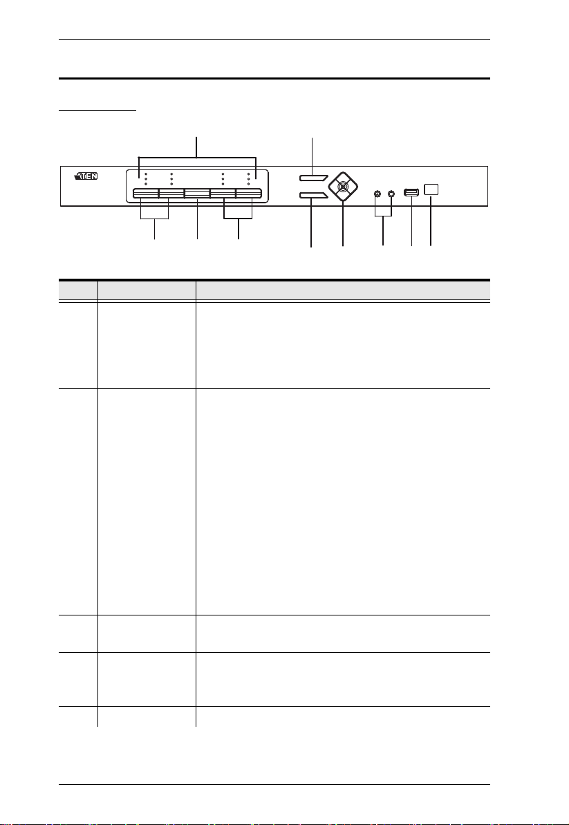
Components
Front View
No. Component Description
1 KVM Status Panel This panel contains LED icons that light to indicate mode
and port status. The Mode and Port Selection Pushbuttons
each have three corresponding LED icons that represent
audio, KVM, and USB Link status. See Display Modes,
page 27, for full details.
2 Port Selection
Pushbuttons
3 Mode Selection
Pushbutton
4 OSD (Esc) button Press this to invoke the on-screen display (OSD) menu.
5 Select button Press this to select an option in the OSD menu.
Press the Port Selection Pushbuttons to manually
switch ports. See Display Modes, page 27, for full
details.
In a cascade setup, press a Port Selection Pushbutton
to switch the console display to the corresponding
secondary CM1164A unit.
Press and hold Port Selection Pushbuttons 1 and 2
simultaneously for 2 seconds to start Auto Scan Mode.
See Auto Scanning, page 43, for full details.
Press and hold Port Selection Pushbuttons 3 and 4
simultaneously for 2 seconds to detect the console
keyboard and mouse again.
This pushbutton allows you to cycle through the three
modes of focus – KVM, audio, and USB Link.
When the OSD menu is enabled, press the OSD button to
go back to the previous menu/submenu.
6
Chapter 1. Introduction
No. Component Description
6 Direction /
Function buttons
Use these buttons to:
Switch between different preset configurations (Fn1 to
Fn4). For details about Function modes, see Preset
Configuration, page 37.
Cycle through the OSD menu/selection. See IR
Remote Control, page 9 for details.
7 Console Audio
Ports
8 USB 2.0
Peripheral Port
9 IR Receiver This receives signals from the IR remote control.
Your speakers and microphone plug in here.
USB 2.0 peripherals (printers, scanners, etc.) plug into this
port.
7
CM1164A User Manual
3
2
4
15
6
Rear View
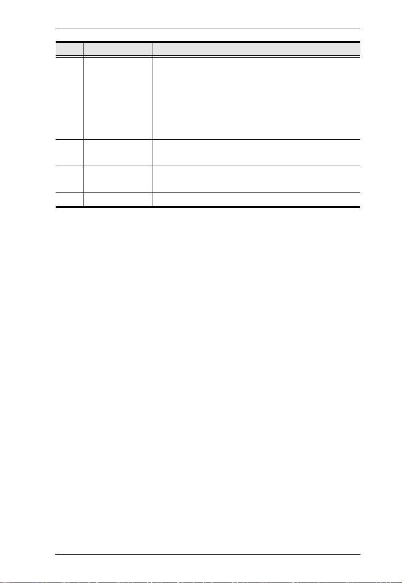
No. Component Description
1 Daisy Chain Control
In / Out ports
(DCC port)
2 Console Ports The cables from your USB keyboard, USB mouse, DVI
3 KVM Ports
4 Power Socket / Power
Switch
5 Grounding Terminal The grounding wire (used to ground the unit) attaches
6 IR Receiver
(Extension)
Use these ports to connect to another CM1164A’s
DCC port to pass keyboard and mouse signals.
You can daisy chain up to four CM1164A units.
If the CM1164A is set up as a single station, you
can control the CM1164A by sending serial
commands through the DCC In port. For details,
see Chapter 6, RS-232 Operation.
console display, a USB peripheral, microphone and
speakers plug into this section.
The cables that link the CM1164A to your DVI-D
Single Link computers plug in here. Each DVI
KVM port is comprised of a microphone jack,
speaker jack, USB type B socket, and a DVI
Single Link connector.You can initiate a firmware
upgrade from the computer connected to these
ports.
Plug in the power cord to the power socket and use
the switch to power on the CM1164A.
here.
This receives signals from the IR remote control
through an IR extension, which can be purchased
separately (see Optional Equipment, page 5).
8
Chapter 1. Introduction
2
5
3
4
1
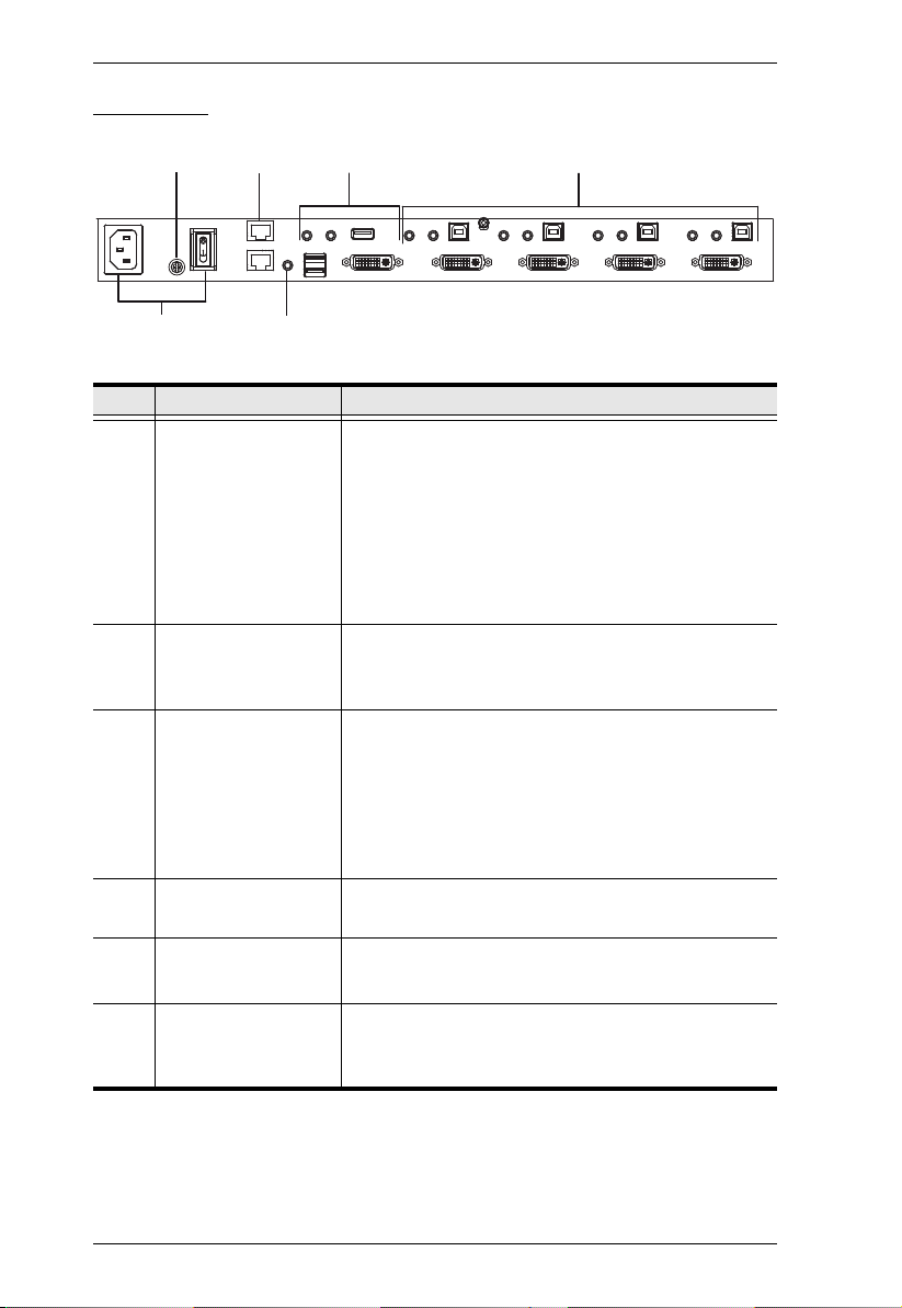
IR Remote Control
No. Component Description
1 OSD button Press this to turn on/turn off the OSD menu.
When the OSD menu is enabled, press the OSD button to
go back to the previous menu/submenu.
2 Fn1 / Fn2 / Fn3 /
Fn4 Buttons and
Select Button
3 Display Mode
buttons
Use these buttons to switch between Function modes (Fn1
to Fn4), and to cycle through the OSD menu/selection.
See Preset Configuration, page 37 for details on how to
store function mode settings, which you can invoke for later
use.
The Fn1~Fn4 buttons are positioned to correspond to the
up / down / left / right direction.
When cycling through the menu options, press the Select
button to go the submenu.
If you want to change or adjust a selection/value, press
the Select button then the Fn1 (up) / Fn2 (left) / Fn3
(down) / Fn4 (right) buttons to go through all the
selections/values. Press the Select button again to
confirm a selection.
Select the Display Mode you want to view. See Display
Modes, page 27.
9

CM1164A User Manual
No. Component Description
4 Port Selection
Buttons 1~4
5 Station Selection
Buttons
Press these buttons to switch ports (1~4).
In a cascade setup, press these buttons to switch the
console display to the corresponding secondary
CM1164A unit.
If the CM1164A is daisy chained to one or several units (up
to 4), press the button corresponding to the CM1164A
device that you want to configure or operate.
10
Chapter 2
1. Important safety information regarding the placement of this
device is provided on page 99. Please review it before
proceeding.
2. Make sure that the power to all devices connected to the
installation is turned off. You must unplug the power cords of
any computers that have the Keyboard Power On function.
Front
Back
Hardware Setup
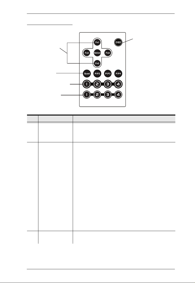
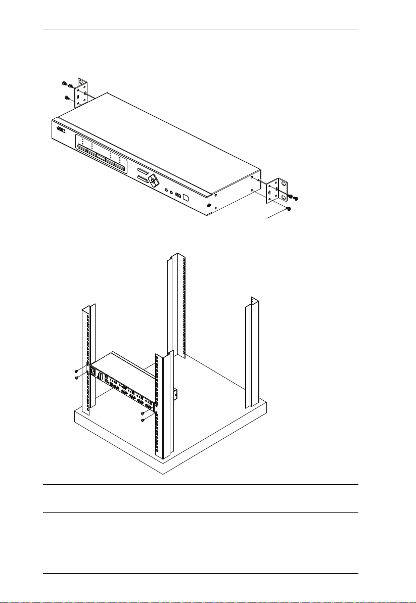
Rack Mounting
For convenience and flexibility, the CM1164A can be mounted on system
racks. To rack mount a unit, do the following:
1. Remove the screws attached to the unit as shown in the diagram below:
Note: You can remove the screws on the front side panels or the back side
panels. The succeeding diagrams show the rack mounting steps for the
back panel.
11
CM1164A User Manual
Phillips hex headPhillips hex head
M3x6M3x6
2. Using the screws provided in the Mounting Kit (not included with this
package), screw the mounting bracket into the side of the unit as show in
the diagram below:
3. Screw the bracket into any convenient location on the rack.
Note: These screws are not provided in the Mounting Kit. We recommend that
you use M5 x 12 Phillips Type I cross, recessed type screws.
12

Chapter 2. Hardware Setup
Grounding
To prevent damage to your installation it is important that all devices are
properly grounded.
Note: The grounding wire is not included in the package. Please contact your
dealer for the appropriate cable.
1. Use a grounding wire to ground the CM1164A by connecting one end of
the wire to the grounding terminal, and the other end of the wire to a
suitable grounded object.
2. Make sure that the computer(s)/device(s) that the CM1164A connects to
are properly grounded.
13

CM1164A User Manual
Installation
You can install the CM1164A as a single station, daisy chain up to 4 CM1164A
units, or cascade up to 4 additional CM1164A units to a primary CM1164A.
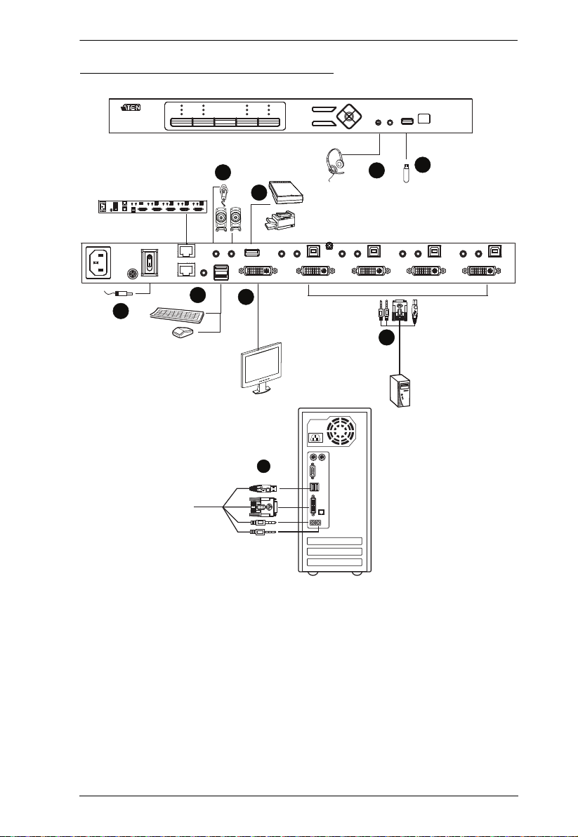
Single Station Installation
To set up a single CM1164A unit, refer to the installation diagram on page 15
(the numbers in the diagrams correspond to the steps below), and do the
following:
1. Plug your USB keyboard and USB mouse into the USB Console Ports
located on the unit’s rear panel.
2. Plug your DVI display into the Console DVI Single Link Port located on
the unit’s rear panel.
3. If you are using separate microphone and speakers, plug them into the
analog audio ports on the unit’s front panel. These audio ports have
priority over those on the rear panel.
4. If you are using separate speakers and microphone, plug them into the
console analog audio ports on the unit’s rear panel.
5. Using the USB DVI KVM cable, plug the DVI-D Single Link cable
connector and the accompanying USB and audio connectors their
corresponding sockets on the rear of the KVM switch.
6. At the other end of the cable, plug the DVI and USB cables into their
respective ports on the computer(s) that is (are) the source of DVI content.
7. Plug your USB peripherals into the Type A sockets (one easy-access port
is located on the front for portable devices; the second is located on the
rear).
8. Plug the power cord into the CM1164A power jack, then plug the other
end of the power cord into an AC power source.
9. Power on the displays and the computers/devices.
Note: The recommended power-on sequence is Port 1–Port 2–Port 3–Port
4.
14
Single Station Installation Diagram
7
8
1
4
2
DVI
7
6
3
5
Chapter 2. Hardware Setup
15

CM1164A User Manual
Daisy Chaining
To display even more computers/video source devices, up to 3 additional
CM1164A units can be daisy chained from the original CM1164A. As many as
16 computers/video source devices can be controlled from a single console in
a complete daisy chain installation. Each CM1164A in a daisy chain requires
its own monitor as the video signals cannot be passed through to other units on
a daisy chain.
To set up a daisy chain installation, make sure that the power to all devices has
been turned off, and do the following:
1. Use an RJ-45 cable to connect the DCC Out port of the primary CM1164A
to the DCC In port of the secondary CM1164A unit(s) (first station out to
second station in, second station out to third station in, etc.).
2. Plug a DVI display into the Console DVI Port located on each unit’s rear
panel.
3. Cable up the computer and the switch according to the information
provided under Single Station Installation, page 14.
4. Repeat the above for any other switches you want to add to the chain (up
to three).
5. Power up the installation: plug in the power cord for the first station, then
power on each station on the installation in turn (second station, then third
station, etc.). After all the stations are up, power on the computers/video
source devices.
6. Make sure the Expansion setting is set to Daisy Chain in the OSD menu
(Advance > Expansion).
7. To switch to a computer in a daisy chain, select from the Control Station
setting in the OSD menu (Advance > Control Station). When switching
to a computer, only the keyboard and mouse signals are connected.
Note: The second, third and forth units in a daisy chain will not be able to
use the IR remote for control. Only the first (primary) CM1164A
can use the IR remote for control.
16

Primary unit
DVI
DVI
DVI
DVI
Secondary unit
Secondary unit
Secondary unit
Chapter 2. Hardware Setup
Daisy Chain Installation Diagram
17

CM1164A User Manual
Cascading
To centrally control up to 4 CM1164A units (16 computers/video sources),
cascade 4 additional CM1164A units to another CM1164A. As many as 16
computers/video source devices can be controlled from a single CM1164A
console in a complete cascade installation.
To set up a cascade installation, make sure that the power to all devices has
been turned off, and then do the following:
1. Connect the console ports of a secondary CM1164A to any of the DVI
KVM Ports on the primary CM1164A using the provided KVM cables.
2. To cascade another CM1164A, repeat step 1.
3. Connect the secondary CM1164A units with computers/video sources. For
detailed steps, see Single Station Installation, page 14.
4. Connect the primary CM1164A with a USB keyboard and a USB mouse.
5. Power up the installed CM1164A units. After all the stations are up, power
on the connected computers/video source devices.
6. Change the installation setting from Daisy Chain to Cascade in the OSD
menu (Advance > Expansion).
7. Each secondary CM1164A unit is recognized as an input source (port 1 ~
4) to the primary CM1164A. To only display the sources of a particular
secondary CM1164A, use any of the following methods:
Press the corresponding front-panel port pushbutton
Press the corresponding port button on the remote control
18
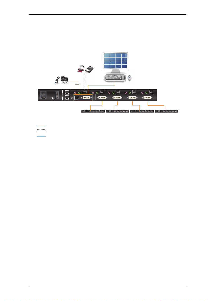
Cascade Installation Diagram
CM1164A Primary Unit
(4X4 multi-view)
USB
Audio
Cat 5e Cable
Video / Keyboard / Mouse
5
13
7
15
2
10
4
12
1
9
3
11
6
8
14
16
Secondary Unit Secondary Unit
Secondary Unit
Secondary Unit
Chapter 2. Hardware Setup
19

CM1164A User Manual
This Page Intentionally Left Blank
20
 Loading...