

ATEN CL5808, CL5816, CL5805 User Manual
LCD KVM Switch
CL5808/CL5816
User Manual
www.aten.com
CL5808/CL5816 User Manual
FCC Information
This is an FCC Class A product. In a domestic environment this product may
cause radio interference in which case the user may be required to take
adequate measures.
This equipment has been tested and found to comply with the limits for a Class
A digital device, pursuant to Part 15 of the FCC Rules. These limits are
designed to provide reasonable protection against harmful interference when
the equipment is operated in a commercial environment. This equipment
generates, uses and can radiate radio frequency energy and, if not installed and
used in accordance with the instruction manual, may cause harmful
interference to radio communications. Operation of this equipment in a
residential area is likely to cause harmful interference in which case the user
will be required to correct the interference at his own expense.
RoHS
This product is RoHS compliant.
SJ/T 11364-2006
The following contains information that relates to China.
ii

CL5808/CL5816 User Manual
User Information
Online Registration
Be sure to register your product at our online support center:
International http://support.aten.com
North America http://www.aten-usa.com/product_registration
Telephone Support
For telephone support, call this number:
International 886-2-8692-6959
China 86-10-5255-0110
Japan 81-3-5615-5811
Korea 82-2-467-6789
North America 1-888-999-ATEN ext 4988
United Kingdom 44-8-4481-58923
User Notice
All information, documentation, and specifications contained in this manual
are subject to change without prior notification by the manufacturer. The
manufacturer makes no representations or warranties, either expressed or
implied, with respect to the contents hereof and specifically disclaims any
warranties as to merchantability or fitness for any particular purpose. Any of
the manufacturer's software described in this manual is sold or licensed as is.
Should the programs prove defective following their purchase, the buyer (and
not the manufacturer, its distributor, or its dealer), assumes the entire cost of all
necessary servicing, repair and any incidental or consequential damages
resulting from any defect in the software.
The manufacturer of this system is not responsible for any radio and/or TV
interference caused by unauthorized modifications to this device. It is the
responsibility of the user to correct such interference.
The manufacturer is not responsible for any damage incurred in the operation
of this system if the correct operational voltage setting was not selected prior
to operation. PLEASE VERIFY THAT THE VOLTAGE SETTING IS
CORRECT BEFORE USE.
iii

CL5808/CL5816 User Manual
© Copyright 2009 - 2011 ATEN® International Co., Ltd.
Manual Part No. PAPE-0326-AT1G
F/W Version: V1.0.082
Manual Date: 2011-01-21
ATEN and the ATEN logo are registered trademarks of ATEN Internatio nal Co., Ltd. All rights rese rved.
All other brand names and trademarks are the registered property of their respective owners.
Package Contents
Basic Package
The basic CL5808/CL5816 package consists of:
1 CL5808/CL5816 KVM Switch with Standard Rack Mounting Kit
2 Custom KVM Cables
1 5-in-1 Console Cable
1 Firmware Upgrade Cable
1Power Cord
1 Grounding Wire
1 User Manual*
1 Quick Start Guide
Optional Equipment
Depending on any optional equipment that you may have purchased, one of the
following may be included in your package:
Standard Rack Mounting Kit - Long
Easy-Installation Rack Mounting Kit - Short
Easy-Installation Rack Mounting Kit - Long
Fingerprint Identification Module
Check to make sure that all the components are present and that nothing got
damaged in shipping. If you encounter a problem, contact your dealer.
Read this manual thoroughly and follow the installation and operation
procedures carefully to prevent any damage to the unit, and/or any of the
devices connected to it.
* Features may have been added to the CL5808/CL5816 since this manual was
printed. Please visit our website to download the most up-to-date version of
the manual.
iv

CL5808/CL5816 User Manual
Contents
FCC Information . . . . . . . . . . . . . . . . . . . . . . . . . . . . . . . . . . . . . . . . . . . . .ii
RoHS. . . . . . . . . . . . . . . . . . . . . . . . . . . . . . . . . . . . . . . . . . . . . . . . . . . . . . ii
SJ/T 11364-2006. . . . . . . . . . . . . . . . . . . . . . . . . . . . . . . . . . . . . . . . . . . . .ii
User Information . . . . . . . . . . . . . . . . . . . . . . . . . . . . . . . . . . . . . . . . . . . . .iii
Online Registration . . . . . . . . . . . . . . . . . . . . . . . . . . . . . . . . . . . . . . . .iii
Telephone Support . . . . . . . . . . . . . . . . . . . . . . . . . . . . . . . . . . . . . . . .iii
User Notice . . . . . . . . . . . . . . . . . . . . . . . . . . . . . . . . . . . . . . . . . . . . . .iii
Package Contents. . . . . . . . . . . . . . . . . . . . . . . . . . . . . . . . . . . . . . . . . . . iv
Basic Package. . . . . . . . . . . . . . . . . . . . . . . . . . . . . . . . . . . . . . . . . . . iv
Optional Equipment. . . . . . . . . . . . . . . . . . . . . . . . . . . . . . . . . . . . . . . iv
About this Manual . . . . . . . . . . . . . . . . . . . . . . . . . . . . . . . . . . . . . . . . . . .viii
Conventions . . . . . . . . . . . . . . . . . . . . . . . . . . . . . . . . . . . . . . . . . . . . . . . ix
Product Information. . . . . . . . . . . . . . . . . . . . . . . . . . . . . . . . . . . . . . . . . . ix
1. Introduction
Overview. . . . . . . . . . . . . . . . . . . . . . . . . . . . . . . . . . . . . . . . . . . . . . . . . . .1
Features . . . . . . . . . . . . . . . . . . . . . . . . . . . . . . . . . . . . . . . . . . . . . . . . . . .3
Requirements . . . . . . . . . . . . . . . . . . . . . . . . . . . . . . . . . . . . . . . . . . . . . . .5
External Console. . . . . . . . . . . . . . . . . . . . . . . . . . . . . . . . . . . . . . . . . .5
Computers. . . . . . . . . . . . . . . . . . . . . . . . . . . . . . . . . . . . . . . . . . . . . . .5
Cables. . . . . . . . . . . . . . . . . . . . . . . . . . . . . . . . . . . . . . . . . . . . . . . . . .5
Operating Systems . . . . . . . . . . . . . . . . . . . . . . . . . . . . . . . . . . . . . . . .6
Components . . . . . . . . . . . . . . . . . . . . . . . . . . . . . . . . . . . . . . . . . . . . . . . .7
Front View. . . . . . . . . . . . . . . . . . . . . . . . . . . . . . . . . . . . . . . . . . . . . . .7
Keyboard Module . . . . . . . . . . . . . . . . . . . . . . . . . . . . . . . . . . . . . . . . .8
LCD Module . . . . . . . . . . . . . . . . . . . . . . . . . . . . . . . . . . . . . . . . . . . . .9
Rear View . . . . . . . . . . . . . . . . . . . . . . . . . . . . . . . . . . . . . . . . . . . . . .10
2. Hardware Setup
Before you Begin. . . . . . . . . . . . . . . . . . . . . . . . . . . . . . . . . . . . . . . . . . . .11
Standard Rack Mounting. . . . . . . . . . . . . . . . . . . . . . . . . . . . . . . . . . . . . .12
Single Stage Installation . . . . . . . . . . . . . . . . . . . . . . . . . . . . . . . . . . . . . .14
Single Stage Installation Diagram . . . . . . . . . . . . . . . . . . . . . . . . . . . .15
Cabling Diagrams . . . . . . . . . . . . . . . . . . . . . . . . . . . . . . . . . . . . . . . .16
Daisy Chaining . . . . . . . . . . . . . . . . . . . . . . . . . . . . . . . . . . . . . . . . . . . . .17
Daisy Chain Installation Diagram . . . . . . . . . . . . . . . . . . . . . . . . . . . .18
3. Basic Operation
Opening the Console . . . . . . . . . . . . . . . . . . . . . . . . . . . . . . . . . . . . . . . .19
Opening Separately. . . . . . . . . . . . . . . . . . . . . . . . . . . . . . . . . . . . . . .19
Opening Together . . . . . . . . . . . . . . . . . . . . . . . . . . . . . . . . . . . . . . . .21
Closing the Console . . . . . . . . . . . . . . . . . . . . . . . . . . . . . . . . . . . . . . . . .22
Operating Precautions . . . . . . . . . . . . . . . . . . . . . . . . . . . . . . . . . . . . . . .24
Powering Off and Restarting. . . . . . . . . . . . . . . . . . . . . . . . . . . . . . . . . . .25
v

CL5808/CL5816 User Manual
LCD OSD Configuration . . . . . . . . . . . . . . . . . . . . . . . . . . . . . . . . . . . . . .26
The LCD Buttons. . . . . . . . . . . . . . . . . . . . . . . . . . . . . . . . . . . . . . . . .26
LCD Adjustment Settings . . . . . . . . . . . . . . . . . . . . . . . . . . . . . . . . . .27
Hot Plugging. . . . . . . . . . . . . . . . . . . . . . . . . . . . . . . . . . . . . . . . . . . . . . . 28
Hot Plugging Stations . . . . . . . . . . . . . . . . . . . . . . . . . . . . . . . . . . . . .28
Hot Plugging KVM Ports . . . . . . . . . . . . . . . . . . . . . . . . . . . . . . . . . . .28
Hot Plugging Console Ports . . . . . . . . . . . . . . . . . . . . . . . . . . . . . . . .28
Port Switching . . . . . . . . . . . . . . . . . . . . . . . . . . . . . . . . . . . . . . . . . . . . . .29
Manual Port Switching . . . . . . . . . . . . . . . . . . . . . . . . . . . . . . . . . . . .29
Port ID Numbering . . . . . . . . . . . . . . . . . . . . . . . . . . . . . . . . . . . . . . . . . .30
USB Peripheral Devices. . . . . . . . . . . . . . . . . . . . . . . . . . . . . . . . . . . . . .30
4. OSD Operation
Overview. . . . . . . . . . . . . . . . . . . . . . . . . . . . . . . . . . . . . . . . . . . . . . . . . . 31
Logging In. . . . . . . . . . . . . . . . . . . . . . . . . . . . . . . . . . . . . . . . . . . . . . . . .31
OSD Main Screen . . . . . . . . . . . . . . . . . . . . . . . . . . . . . . . . . . . . . . . . . . .32
OSD Main Screen Headings. . . . . . . . . . . . . . . . . . . . . . . . . . . . . . . . . . .33
OSD Navigation . . . . . . . . . . . . . . . . . . . . . . . . . . . . . . . . . . . . . . . . . . . .33
OSD Functions . . . . . . . . . . . . . . . . . . . . . . . . . . . . . . . . . . . . . . . . . . . . .34
F1: GOTO. . . . . . . . . . . . . . . . . . . . . . . . . . . . . . . . . . . . . . . . . . . . . .34
F2: LIST . . . . . . . . . . . . . . . . . . . . . . . . . . . . . . . . . . . . . . . . . . . . . . .35
F3: SET. . . . . . . . . . . . . . . . . . . . . . . . . . . . . . . . . . . . . . . . . . . . . . . .36
F4: ADM . . . . . . . . . . . . . . . . . . . . . . . . . . . . . . . . . . . . . . . . . . . . . . .38
F5: SKP. . . . . . . . . . . . . . . . . . . . . . . . . . . . . . . . . . . . . . . . . . . . . . . .42
F6: BRC . . . . . . . . . . . . . . . . . . . . . . . . . . . . . . . . . . . . . . . . . . . . . . .43
F7: SCAN . . . . . . . . . . . . . . . . . . . . . . . . . . . . . . . . . . . . . . . . . . . . . .44
F8: LOUT . . . . . . . . . . . . . . . . . . . . . . . . . . . . . . . . . . . . . . . . . . . . . .44
5. Keyboard Port Operation
Hotkey Port Control . . . . . . . . . . . . . . . . . . . . . . . . . . . . . . . . . . . . . . . . .45
Hotkey Mode. . . . . . . . . . . . . . . . . . . . . . . . . . . . . . . . . . . . . . . . . . . . . . .46
Invoking Hotkey Mode. . . . . . . . . . . . . . . . . . . . . . . . . . . . . . . . . . . . .46
Hotkey Mode Active . . . . . . . . . . . . . . . . . . . . . . . . . . . . . . . . . . . . . .46
Exiting Hotkey Mode. . . . . . . . . . . . . . . . . . . . . . . . . . . . . . . . . . . . . .46
Selecting the Active Port. . . . . . . . . . . . . . . . . . . . . . . . . . . . . . . . . . . . . .47
Auto Scan Mode. . . . . . . . . . . . . . . . . . . . . . . . . . . . . . . . . . . . . . . . . . . .48
Invoking Auto Scan. . . . . . . . . . . . . . . . . . . . . . . . . . . . . . . . . . . . . . .48
Exiting Auto Scan . . . . . . . . . . . . . . . . . . . . . . . . . . . . . . . . . . . . . . . .48
Pausing Auto Scan . . . . . . . . . . . . . . . . . . . . . . . . . . . . . . . . . . . . . . .48
Skip Mode. . . . . . . . . . . . . . . . . . . . . . . . . . . . . . . . . . . . . . . . . . . . . . . . . 49
Invoking Skip Mode. . . . . . . . . . . . . . . . . . . . . . . . . . . . . . . . . . . . . . .49
Exiting Skip Mode . . . . . . . . . . . . . . . . . . . . . . . . . . . . . . . . . . . . . . . .49
Computer Keyboard/Mouse Reset . . . . . . . . . . . . . . . . . . . . . . . . . . . . . . 50
Hotkey Beeper Control . . . . . . . . . . . . . . . . . . . . . . . . . . . . . . . . . . . . . . .50
Hotkey Invocation Key Selection . . . . . . . . . . . . . . . . . . . . . . . . . . . . . . .51
OSD Hotkey Selection . . . . . . . . . . . . . . . . . . . . . . . . . . . . . . . . . . . . . . .51
vi

CL5808/CL5816 User Manual
Port OS Selection . . . . . . . . . . . . . . . . . . . . . . . . . . . . . . . . . . . . . . . . . . .52
Restore the Default Values. . . . . . . . . . . . . . . . . . . . . . . . . . . . . . . . . . . .52
Hotkey Summary Table. . . . . . . . . . . . . . . . . . . . . . . . . . . . . . . . . . . . . . .53
6. Keyboard Emulation
Mac Keyboard. . . . . . . . . . . . . . . . . . . . . . . . . . . . . . . . . . . . . . . . . . . . . .55
Sun Keyboard . . . . . . . . . . . . . . . . . . . . . . . . . . . . . . . . . . . . . . . . . . . . . .56
7. The Firmware Upgrade Utility
Introduction . . . . . . . . . . . . . . . . . . . . . . . . . . . . . . . . . . . . . . . . . . . . . . . .57
Downloading the Firmware Upgrade Package . . . . . . . . . . . . . . . . . . . . .57
Preparation . . . . . . . . . . . . . . . . . . . . . . . . . . . . . . . . . . . . . . . . . . . . . . . .58
Starting the Upgrade. . . . . . . . . . . . . . . . . . . . . . . . . . . . . . . . . . . . . . . . .59
Upgrade Succeeded . . . . . . . . . . . . . . . . . . . . . . . . . . . . . . . . . . . . . . . . .61
Upgrade Failed . . . . . . . . . . . . . . . . . . . . . . . . . . . . . . . . . . . . . . . . . . . . .61
Firmware Upgrade Recovery . . . . . . . . . . . . . . . . . . . . . . . . . . . . . . . . . .62
Appendix
Safety Instructions. . . . . . . . . . . . . . . . . . . . . . . . . . . . . . . . . . . . . . . . . . .63
General . . . . . . . . . . . . . . . . . . . . . . . . . . . . . . . . . . . . . . . . . . . . . . . .63
Rack Mounting . . . . . . . . . . . . . . . . . . . . . . . . . . . . . . . . . . . . . . . . . .65
Technical Support. . . . . . . . . . . . . . . . . . . . . . . . . . . . . . . . . . . . . . . . . . .66
International. . . . . . . . . . . . . . . . . . . . . . . . . . . . . . . . . . . . . . . . . . . . .66
North America . . . . . . . . . . . . . . . . . . . . . . . . . . . . . . . . . . . . . . . . . . .66
Specifications . . . . . . . . . . . . . . . . . . . . . . . . . . . . . . . . . . . . . . . . . . . . . .67
Connection Tables . . . . . . . . . . . . . . . . . . . . . . . . . . . . . . . . . . . . . . . . . .69
CL5808 to Compatible 8-Port Switches . . . . . . . . . . . . . . . . . . . . . . .69
CL5808 to Compatible 16-Port Switches . . . . . . . . . . . . . . . . . . . . . .69
CL5816 to Compatible 8-Port Switches . . . . . . . . . . . . . . . . . . . . . . .70
CL5816 to Compatible 16-Port Switches . . . . . . . . . . . . . . . . . . . . . .70
Supported KVM Switches . . . . . . . . . . . . . . . . . . . . . . . . . . . . . . . . . . . . .71
Clear Login Information. . . . . . . . . . . . . . . . . . . . . . . . . . . . . . . . . . . . . . .72
OSD Factory Default Settings. . . . . . . . . . . . . . . . . . . . . . . . . . . . . . . . . .73
Optional Rack Mounting . . . . . . . . . . . . . . . . . . . . . . . . . . . . . . . . . . . . . . 74
Troubleshooting . . . . . . . . . . . . . . . . . . . . . . . . . . . . . . . . . . . . . . . . . . . .77
Overview . . . . . . . . . . . . . . . . . . . . . . . . . . . . . . . . . . . . . . . . . . . . . . .77
Keyboard Invocation Keys . . . . . . . . . . . . . . . . . . . . . . . . . . . . . . . . . . . .77
About SPHD Connectors . . . . . . . . . . . . . . . . . . . . . . . . . . . . . . . . . . . . .78
Limited Warranty. . . . . . . . . . . . . . . . . . . . . . . . . . . . . . . . . . . . . . . . . . . .78
vii

CL5808/CL5816 User Manual
About this Manual
This User Manual is provided to help you get the most from your c/c system.
It covers all aspects of installation, configuration and operation. An overview
of the information found in the manual is provided below.
Chapter 1, Introduction, introduces you to the CL5808/CL5816 system.
Its purpose, features and benefits are presented, and its front and back panel
components are described.
Chapter 2, Hardware Setup, describes how to set up your installation. The
necessary steps – from a basic single stage hookup to a complete 32 switch
daisy chained operation are provided.
Chapter 3, Basic Operation, explains the fundamental concepts involved
in operating the CL5808/CL5816.
Chapter 4, OSD Operation, provides a complete description of the
CL5808/CL5816's OSD (On Screen Display), and how to work with it.
Chapter 5, Keyboard Port Operation, details all of the concepts and
procedures involved in the Hotkey operation of your CL5808/CL5816
installation.
Chapter 6, Keyboard Emulation, provides tables that list the PC to Mac
and PC to Sun keyboard emulation mappings.
Chapter 7, The Firmware Upgrade Utility, explains how to use this
utility to upgrade the CL5808/CL5816's firmware with the latest available
versions.
An Appendix, provides specifications and other technical information
regarding the CL5808/CL5816.
viii

Conventions
This manual uses the following conventions:
Monospaced Indicates text that you should key in.
[ ] Indicates keys you should press. For example, [Enter] means to
press the Enter key. If keys need to be chorded, they appear
together in the same bracket with a plus sign between them:
[Ctrl+Alt].
1. Numbered lists represent procedures with sequential steps.
♦ Bullet lists provide information, but do not involve sequential steps.
→ Indicates selecting the option (on a menu or dialog box, for
example), that comes next. For example, Start
open the Start menu, and then select Run.
Indicates critical information.
Product Information
CL5808/CL5816 User Manual
→ Run means to
For information about all ALTUSEN products and how they can help you
connect without limits, visit ALTUSEN on the Web or contact an ALTUSEN
Authorized Reseller. Visit ALTUSEN on the Web for a list of locations and
telephone numbers:
International http://www.aten.com
North America http://www.aten-usa.com
ix

CL5808/CL5816 User Manual
This Page Intentionally Left Blank
x

Chapter 1
Introduction
Overview
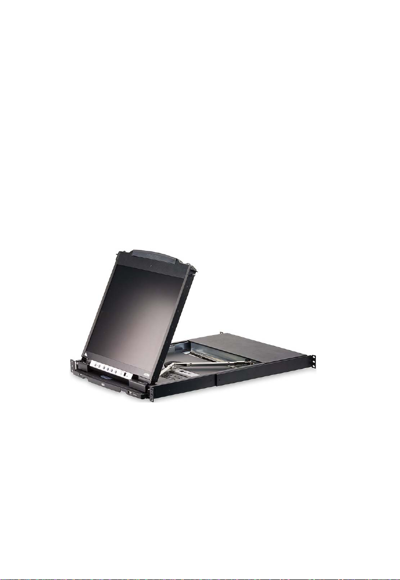
The CL5808/CL5816 LCD KVM Switch is an integrated LCD console and
keyboard, video, and mouse (KVM) switch that offers secure access to 8 or 16
attached computers and mounts in only 1U of rack space.
The CL5808/CL5816’s 19” LCD monitor and keyboard/touch pad modules
slide independently of each other. To maximize space in your data center, the
keyboard/touch pad module slides back to "hide away" when not in use, while
the thin profile LCD monitor rotates back – flush against the rack – allowing
convenient monitoring of computer activity. An extra console port is provided
on the rear panel to manage the LCD KVM switch from an optional external
console (monitor, keyboard, and mouse). For added convenience it also
supports an external USB mouse.
The CL5808/CL5816 supports both PS/2 and USB keyboards and mice for the
connected computers, and the CL5808/CL5816 supports USB peripheral
devices to be used with the attached computers. A single CL5808/CL5816 can
control up to 8 or 16 computers. As many as 31 additional compatible KVM
switches can be daisy chained together, so that up to 256 or 512 computers can
all be controlled from a single keyboard, monitor, and mouse console (See the
Appendix for a list of compatible ATEN switches).
The CL5808/CL5816 is built on a modular design. The KVM section can be
detached from the switch section for convenient maintenance and repair.
There are two models in the series as outlined in the following table:
Model LCD Panel KVM Ports Power
CL5808 19" 8 AC
CL5816 19" 16 AC
Your CL5808/CL5816 investment is protected by an included firmware
upgrade utility. You can stay current with the latest functionality
improvements by downloading firmware update files from our website as they
become available, and using the utility to quickly and conveniently perform the
upgrade.
1

CL5808/CL5816 User Manual
Setup is fast and easy: plugging cables into their appropriate ports is all that is
entailed. Because the CL5808/CL5816 intercepts keyboard input directly,
there is no software to configure, no need to get involved in complex
installation routines, nor any need to be concerned with incompatibility
problems.
Access to any computer connected to the installation is easily accomplished
either by entering Hotkey combinations from the keyboard, or by means of a
powerful, mouse driven, OSD (on-screen display) menu system. A convenient
Auto Scan feature also permits automatic scanning and monitoring of the
activities of all computers running on the installation one by one.
There is no better way to save time and money than with a CL5808/CL5816
installation. By using the CL5808/CL5816 with its sliding LCD console to
manage your installation, you: eliminate the expense of having to purchase a
separate keyboard, monitor, and mouse for each computer; save all the space
those extra components would take up; save the space that a keyboard, monitor,
and mouse would take with a standard KVM switch; save on energy costs; and
eliminate the inconvenience and wasted effort involved in consta ntl y moving
from one computer to another.
2

1. Introduction
Features
Integrated KVM console with 19” LCD in a Dual-Rail SlideawayTM
housing
Space saving technology – up to two consoles (one bus) control up to 8 or
16 computers
Daisy chain up to 31 additional units – control up to 256 (CL5808) or 512
(CL5816) computers from a single console
Dual Interface – supports computers with PS/2 or USB keyboards and mice
USB port – allows each connected computer to access an attached USB
peripheral*
Multiplatform support – Windows, Linux, Mac, and Sun
Supports multimedia USB keyboards for PC, Mac and Sun
Auto PS/2 and USB interface detection
Keyboard and mouse emulation (PS/2 and USB) for smooth switching and
simultaneous booting of multiple computers even when the console focus
is elsewhere
Superior video quality – supports resolutions up to 1280 x 1024 @ 75 Hz
No software required – convenient computer selection via mouse-driven,
intuitive OSD (on-screen display) menus and Hotkeys
Auto-senses station's position on daisy chained installations; no need for
manual dip switch setting; front panel led indicates station's position
Port names automatically reconfigu red when station sequence is changed
T wo level passwor d security – authorized users view and control comput ers
Supports one administrator and four user accounts with separate profiles
Auto Scan mode enables continuous monitoring of user-selected computers
Broadcast support – commands from the keyboard can be broadcast to all
available computers on the installation
Hot pluggable – add or remove computers without having to power down
the switch
Beeper on/off via Hotkey and OSD
Firmware upgrades to all the chained KVM switches at the same time via
the daisy chain cable
* Only for computers connected with USB KVM cables.
3

CL5808/CL5816 User Manual
Extra console port – manage computers from an external console (monitor,
USB or PS/2 keyboard and mouse)
Supports external USB mouse
Convenient direct port selector buttons (8 or 16) each with 2 LEDs that
indicate whether the server is powered-on and selected.
Station Up/Down Navigation buttons with a 2x7 segment LED display
indicating the currently selected station of a daisy chained installation.
Port Navigation Buttons located on the front LCD panel for quick port
switching when the keyboard module is in the Slideaway
TM
position
behind and hidden.
Dedicated Hotkey mode and OSD Invocation Keys reduce the number of
keystrokes and provide quick access to these functions
OSD tree structure makes finding and managing computers easy
Console lock – enables the console drawer to remain securely locked away
when not in use
OSD port list automatically expands when new stations are added
Security – Administrator/User password authorization for enhanced
security protection; Administrator access rights synchronized between
master and slave stations
OSD screen automatically adjusts to resolution changes
Two types of logout: manual and timed
Slideaway
TM
housing is slightly less than 1U with top and bottom
clearance for smooth operation in 1U of rack space
DDC emulation – video settings of each computer are automatically
adjusted for optimal output to the monitor
Standard 105-key keyboard
Keyboard status restored when switching computers
4
1. Introduction
Requirements
External Console
The following hardware components are required for the external console:
A VGA, SVGA, or multisync monitor capable of displaying the highest
resolution provided by any computer in the installation.
A USB or PS/2 keyboard and mouse
Computers
The following equipment must be installed on each computer:
A VGA, SVGA, or multisync video graphics card with an HDB-15 port.
Note: The integrated LCD monitor's maximum resolution is
1280 x 1024 @ 75 Hz. Make sure that none of the computer
resolution settings exceed the LCD monitor's maximum resolution.
PS/2 mouse and keyboard ports (6-pin Mini-DIN), or at least one USB port.
Direct support Sun USB systems; or, for Sun legacy systems, an ATEN
CV130A Sun Console Converter.
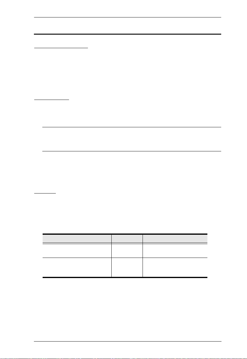
Cables
Substandard cables may damage the connected devices or degrade overall
performance. For optimum signal integrity and to simplify the layout, we
strongly recommend that you use the high quality CS Custom Cable sets
described below:
Function Length Part Number
KVM switch to KVM switch
(Daisy chaining)
KVM switch to computer
(USB/PS2)
0.6 m
1.8 m
1.2 m
1.8 m
3.0 m
2L-1700
2L-1701
2L-5301UP
2L-5302UP
2L-5303UP
5
CL5808/CL5816 User Manual
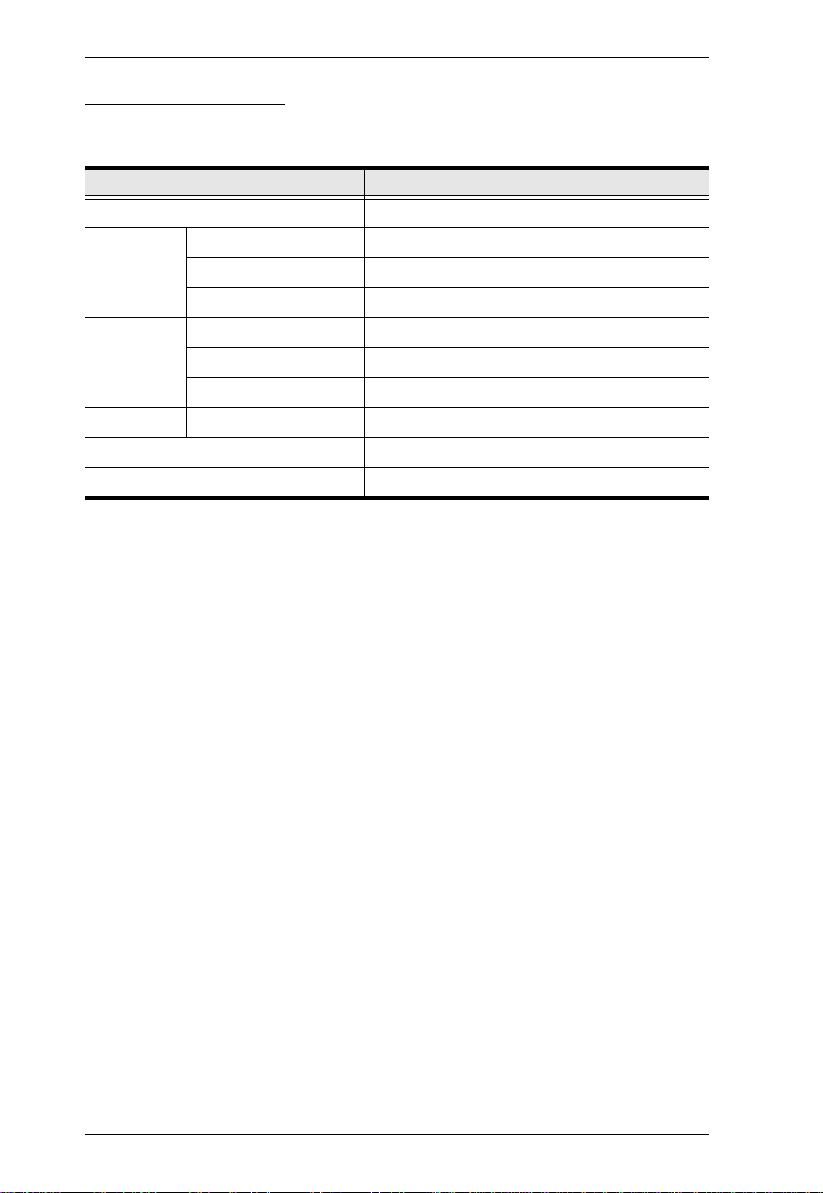
Operating Systems
Supported operating systems are shown in the table, below:
OS Version
Windows 2000 and higher
Linux RedHat 7.1 and higher
SuSE 9.0 and higher
Mandriva (Mandrake) 9.0 and higher
UNIX AIX 4.3 and higher
FreeBSD 4.2 and higher
Sun Solaris 8 and higher
Novell Netware 5.0 and higher
Mac OS 9 and higher
DOS 6.22
6
Components
1
2
2
3
4
5
6
7
8
9
10
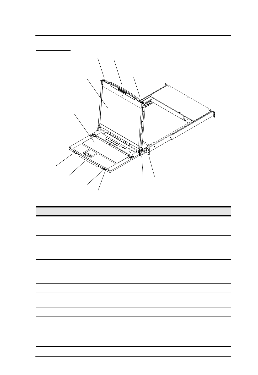
Front View
1. Introduction
No. Component Description
1 Upper Handle Pull to slide the LCD module out; push to slide it in.
2 Module Release
Catches
3 LCD Module See LC D Module, page 9.
4 Keyboard Module See Keyboard Module, page 8.
5 USB Port The USB port is available to connect a USB 1.1 peripheral
6 Lower Handle Pull to slide the Keyboard module out; push to slide it in.
7 External Mouse
Port
8 Power LED Lights (blue) to indicate that the unit is receiving power.
9 LCD Release
Catch
8 Rack Mounting
Tabs
See Opening the Console, page 19, for details on sliding the
console in and out
In order to slide the console out, you must first release it by
sliding these catches to the inside.
device (flash drive, CD-ROM drive, etc.) to the switch.
A USB mouse port is provided for users who prefer to use an
external mouse.
These catches (one on each side) release the LCD Module
so that you can slide it away.
Rack mounting tabs are located at each corner of the unit.
See Standard Rack Mounting, page 12, for details.
7
CL5808/CL5816 User Manual
2
1
3
4
5
6
7
8
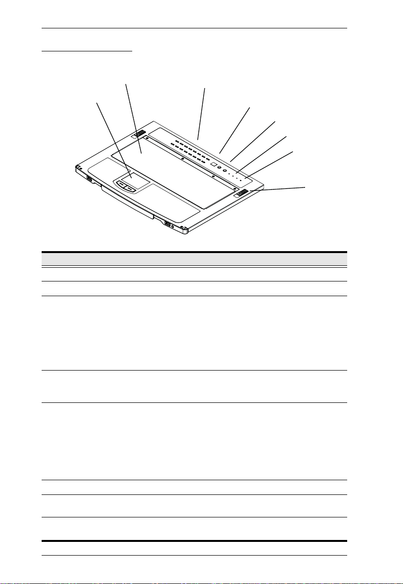
Keyboard Module
No. Component Description
1 Touchpad Standard mouse touchpad
2 Keyboard Standard 105-key keyboard
3 Port Selection
Buttons and LEDs
4 Station ID LED In a daisy chained installation, the Station ID of the currently
5 Station Selection
Buttons
6 Lock LEDs Num Lock, Caps Lock, Scroll Lock LEDs are located here.
7 Reset Switch Located to the right of the Lock LEDs. Press this recessed
8 Keyboard
Release Catch
To access a Port on the currently selected Station press its
corresponding port selection button. Indicator LEDs are built
into the switches:
An On Line LED lights to indicate that the computer
attached to its corresponding port is up and running.
A Selected LED lights to indicate which port has the KVM
focus.
selected station displays as a 2 digit figure in this panel.
See Manual Port Switching, page 29 for further details.
In a daisy chained installation, press the UP or DOWN
button to cycle to the desired Station.
The left (DOWN) button shifts the KVM focus down the
chain (Station 2
cycles back to the last station.
The right (UP) button shifts the KVM focus up the chain.
After the last station, it cycles to Station 1.
→ Station 1, etc.). After Station 1, it
switch in with a small object to perform a system reset.
These catches (one on each side) release the keyboard/
touchpad module so you can slide it away.
8
1. Introduction
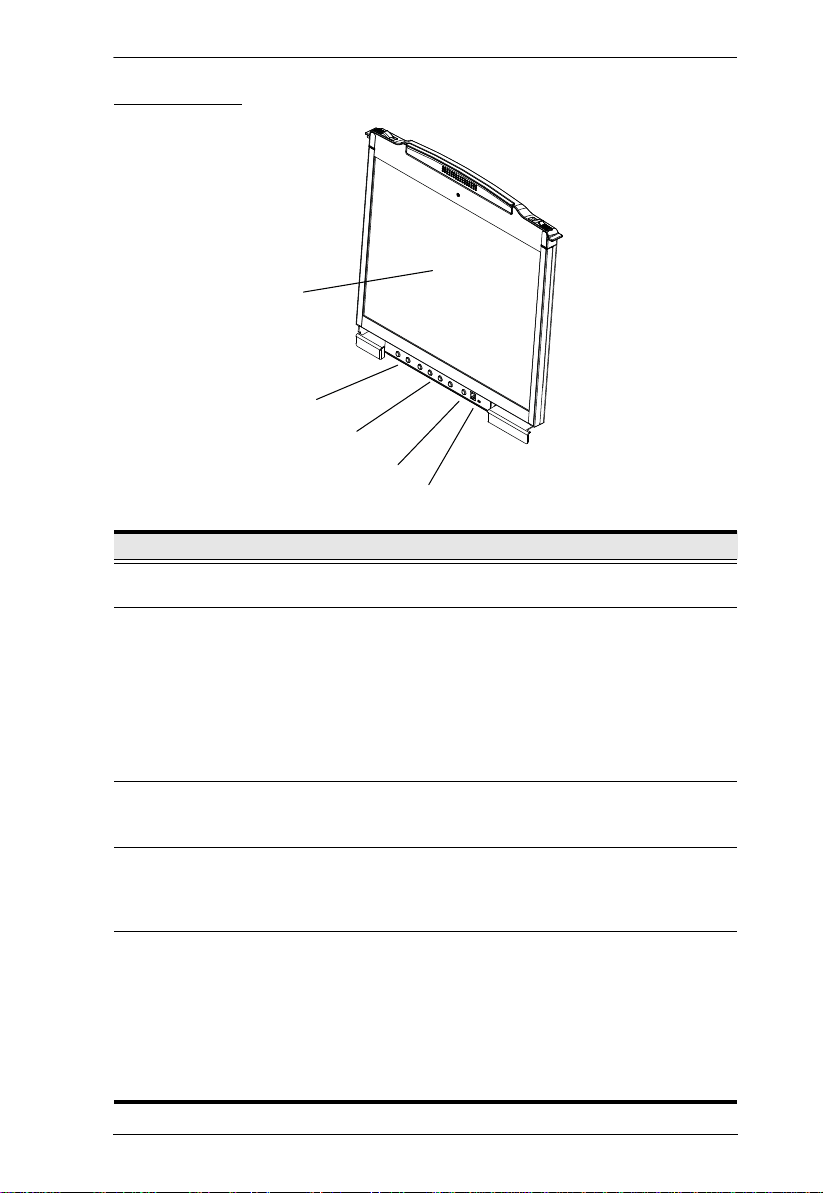
LCD Module
1
2
3
4
5
No. Component Description
1 LCD Display After sliding the LCD module out, flip up the cover to access
2 Port Navigation
Switches
the LCD monitor.
These buttons can be used to access a port when the
Keyboard Module isn’t extended. Press the UP or DOWN
button to cycle forward or backward through the ports.
The left (DOWN) button shifts the KVM focus down the
chain (Port 2
last port.
→ Port 1, etc.). After Port 1, it cycles to the
The right (UP) button shifts the KVM focus up the chain.
After the last port, it cycles back to Port 1.
3 LCD OSD
Controls
4 LCD Power
Button
5 Firmware
Upgrade
Section
Buttons to control the position and picture settings of the
LCD display are located here. See LCD OSD Configuration,
page 26, for details.
Press this button to turn the LCD monitor on and off. When
the LCD monitor is off, this button illuminates; when the LCD
monitor is on, this button does not illuminate. (This function
only affects the monitor, not the KVM switch itself.)
Firmware Upgrade Port: The Firmware Upgrade Cable
that transfers the firmware upgrade data from the administrator's computer to the CL5808/CL5816 plugs into this
RJ-11 connector.
Firmware Upgrade Switch: During normal operation this
switch should be in the NORMAL position. (See The
Firmware Upgrade Utility, page 57 for firmware upgrading
details.)
9
CL5808/CL5816 User Manual
12 34
56
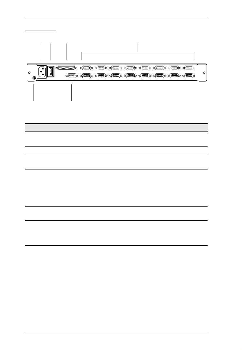
Rear View
No. Component Description
1 Power Socket This is a standard 3-prong AC power socket. The power cord
2 Power Switch This standard rocker switch powers the unit on and off.
3 Daisy Chain Port When daisy chaining units, the daisy chain cable plugs in
4 KVM Port
Section
5 Grounding
Terminal
6 External
Console Port
from an AC source plugs in here.
here.
The cables that link to the computers plug in here.
Note: The shape of these SPHD connectors has been
specifically modified so that only KVM cables designed to
work with this switch can plug in (see Cables, page 5 for
details). Do NOT attempt to use ordinary 15 pin VGA
connector cables to link these ports to the computers.
The grounding wire used to ground the switch attaches here.
For flexibility and convenience, the CL5808/CL5816 supports
an independent, external, KVM console. If you choose to
install an external console, the Console Cable (supplied with
the CL5808/CL5816 package), plugs in here.
10
Hardware Setup
1. Important safety information regarding the placement of this
device is provided on page 63. Please review it before
proceeding.
2. Make sure that power to all the devices you will be connecting
up has been turned off. You must unplug the power cords of any
computers that have the Keyboard Power On function.
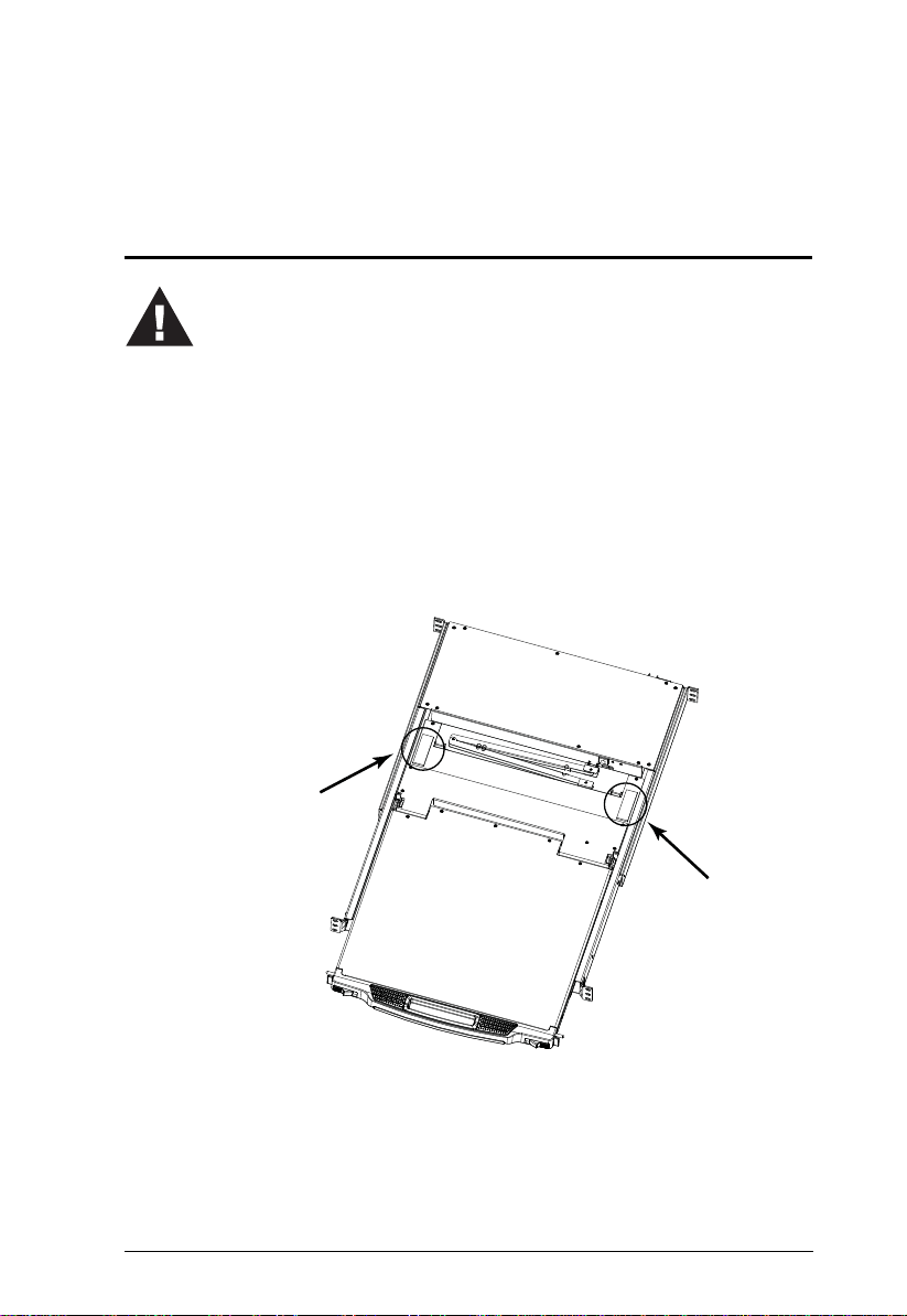
3. Packing material has been inserted to protect the CL5808/
CL5816 during shipping. Slide the LCD module out
(see Opening the Console, page 19, for det ails), until the
packing material is visible. Remove the packing material before
installing the unit, as shown in the diagram below.
Before you Begin
Chapter 2
11
CL5808/CL5816 User Manual
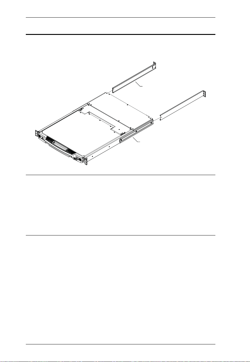
L Brackets
Side Mountng
Brackets
Standard Rack Mounting
A standard rack mounting kit is provided with your CL5808/CL5816. The kit
enables the CL5808/CL5816 to be mounted in rack with a depth of 52–85 cm.
Note: 1. It takes two people to mount the switch: one to hold it in place, the
other to screw it in.
2. The standard rack mounting kit does not include screws or cage nuts.
If you need additional screws or cage nuts, contact your rack dealer.
3. Optional mounting kits - including single person Easy Installation
kits - are available with a separate purchase. see Optional Rack
Mounting, page 74, for details.
12
2. Hardware Setup
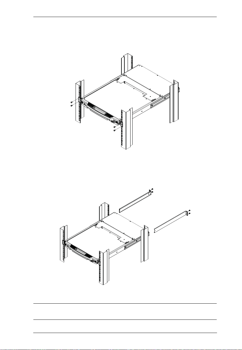
To rack mount the CL5808/CL5816, do the following:
1. While one person positions the switch in the rack and holds it in place, the
second person loosely screws the front brackets to the rack.
2. While the first person still holds the switch in place, the second person
slides the L brackets into the switch's side mounting brackets, from the
rear until the bracket flanges contact the rack, then screws the L brackets
to the rack.
3. After the L brackets have been secured, tighten the front bracket screws.
Note: Allow at least 5.1 cm on each side for proper ventilation, and at least
12.7 cm at the back for the power cord and cable clearance.
13

CL5808/CL5816 User Manual
Single Stage Installation
In a single stage installation, there are no additional switches daisy chained
from the first unit. To set up a single stage installation, refer to the installation
diagrams on the following pages (the numbers in the diagrams correspond to
the numbers of the installation steps), and do the following:
1. Ground the CL5808/CL5816 by connecting one end of the grounding wire
provided with your switch to the grounding terminal, and the other end of
the wire to a suitable grounded object.
Note: Do not omit this step. Proper grounding helps to prevent damage to
the unit from surges or static electricity.
2. If you choose to connect an external console to the CL5808/CL5816, use
the console cable provided to plug a keyboard, monitor, and mouse into
the Console Port. See Console Cable Installation Diagram, page 16.
Note: 1. Connecting an external console is optional.
2. You can use any combination of keyboard and mouse
connections. For example, you can use a PS/2 keyboard with a
USB mouse.
3. For each of the computers you are installing, use a KVM cable set (as
described in the Cables section on page 5), to connect any available KVM
port to the computer's keyboard, video and mouse ports. See KVM Cable
Installation Diagrams, page 16.
4. Plug the power cord into the CL5808/CL5816 power socket and into a AC
power source.
After you have completed the installation procedures, power on the CL5808/
CL5816 (see Powering Off and Restarting, page 25 for details). After the
CL5808/CL5816 is powered on, power on the computers.
14
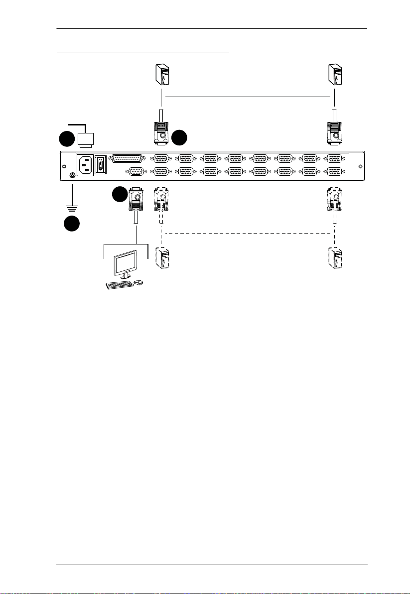
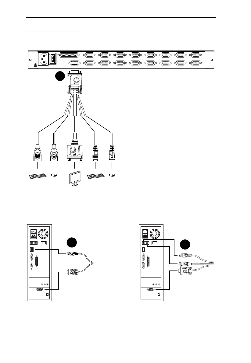
Single Stage Installation Diagram
2. Hardware Setup
4
3
2
1
15
CL5808/CL5816 User Manual
VGA
USB
PS/2
2
Cabling Diagrams
Console Cable Installation Diagram
KVM Cable Installation Diagrams
USB KVM Cable Connection PS/2 KVM Cable Connection
3
16
3

2. Hardware Setup
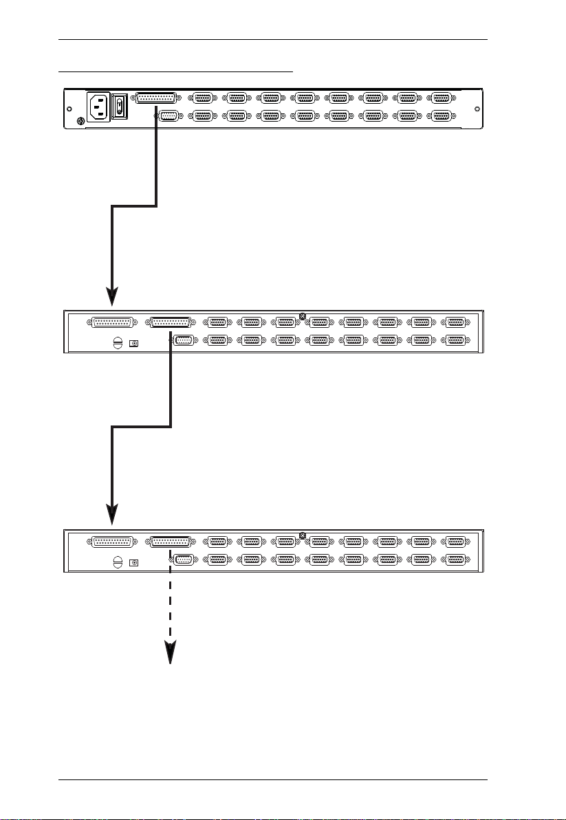
Daisy Chaining
To control even more computers, up to 31 compatible KVM switches can be
daisy chained from the first stage CL5808/CL5816 (see Supported KVM
Switches, page 71, for details). In a complete installation, as many as 256 or
512 computers can be controlled from the CL5808/CL5816. Tables showing
the relation between the number of computers and the number of units needed
to control them are provided on page 69 in the Appendix.
To set up a daisy chain installation, first make sure that power to all the devices
you will be connecting have been turned off. Then, refer to the daisy chain
installation diagram on page 18, as you do the following:
1. Use a daisy chain cable set (described in the Cables section, page 5), to
connect the Chain Out port of the parent CL5808/CL5816 to the Chain In
port of the child switch (first station out to second station in, second
station out to third station in, etc.).
Note: 1. The maximum distance between any two stations is 15 m.
2. The total maximum distance from the first station to the last
station is 100 m, regardless of the number of stations in the chain.
The daisy-chain functionality is not guaranteed should any of the
inter-station distances follow Note 1 above.
2. Use compatible KVM cable sets to connect any available KVM port on the
daisy chained switch to the keyboard, video and mouse ports of the
computers you are installing. See KVM Cable Installation Diag rams ,
page 16.
3. Repeat the above steps for any additional units you wish to add to the
chain.
4. Power up the installation according to the following procedure:
a) Power on the CL5808/CL5816.
b) Power on each station on the installation in turn (second station, then
third station, etc.).
In each case, wait for the station ID to be ascertained and displayed on
the current station before powering on the next one.
c) After all the stations are turned on, power on the computers.
17
CL5808/CL5816 User Manual
Daisy Chain Installation Diagram
18
 Loading...