

Page 1
4 - P o r t U S B H D M I M u l t i - V i e w D u a l R a i l
WideScreen LCD KVM Switch
CL3884NW
User Manual
www.aten.com
Page 2
CL3884NW User Manual
EMC Information
FEDERAL COMMUNICATIONS COMMISSION INTERFERENCE
STATEMENT: This equipment has been tested and found to comply with the
limits for a Class A digital device, pursuant to Part 15 of the FCC Rules. These
limits are designed to provide reasonable protection against harmful
interference when the equipment is operated in a commercial environment.
This equipment generates, uses, and can radiate radio frequency energy and, if
not installed and used in accordance with the instruction manual, may cause
harmful interference to radio communications. Operation of this equipment in
a residential area is likely to cause harmful interference in which case the user
will be required to correct the interference at his own expense.
The device complies with Part 15 of the FCC Rules. Operation is subject to the
following two conditions: (1) this device may not cause harmful interference,
and (2) this device must accept any interference received, including
interference that may cause undesired operation.
FCC Caution: Any changes or modifications not expressly approved by the
party responsible for compliance could void the user's authority to operate this
equipment.
Warning: Operation of this equipment in a residential environment could
cause radio interference.
Achtung: Der Gebrauch dieses Geräts in Wohnumgebung kann
Funkstörungen verursachen.
KCC Statement
RoHS
This product is RoHS compliant.
© Copyright 2021 ATEN® International Co., Ltd.
ATEN and the ATEN logo are registered trademarks of ATEN International Co., Ltd. All rights reserved.
All other brand names and trademarks are the registered property of their respective owners. The
terms HDMI, HDMI High-Definition Multimedia Interface, and the HDMI Logo are trademarks or
registered trademarks of HDMI Licensing Administrator, Inc.
ii
Manual Date: 2021-01-05
Page 3

CL3884NW User Manual
User Information
Online Registration
Be sure to register your product at our online support center:
International http://eservice.aten.com
Telephone Support
For telephone support, call this number:
International 886-2-8692-6959
China 86-400-810-0-810
Japan 81-3-5615-5811
Korea 82-2-467-6789
North America 1-888-999-ATEN ext 4988
1- 949-428-1111
User Notice
All information, documentation, and specifications contained in this manual
are subject to change without prior notification by the manufacturer. The
manufacturer makes no representations or warranties, either expressed or
implied, with respect to the contents hereof and specifically disclaims any
warranties as to merchantability or fitness for any particular purpose. Any of
the manufacturer's software described in this manual is sold or licensed as is.
Should the programs prove defective following their purchase, the buyer (and
not the manufacturer, its distributor, or its dealer), assumes the entire cost of all
necessary servicing, repair and any incidental or consequential damages
resulting from any defect in the software.
The manufacturer of this system is not responsible for any radio and/or TV
interference caused by unauthorized modifications to this device. It is the
responsibility of the user to correct such interference.
The manufacturer is not responsible for any damage incurred in the operation
of this system if the correct operational voltage setting was not selected prior
to operation. PLEASE VERIFY THAT THE VOLTAGE SETTING IS
CORRECT BEFORE USE.
iii
Page 4

CL3884NW User Manual
Package Contents
The CL3884NW package consists of:
1 CL3884NW LCD KVM Switch with Standard Rack Mount Kit
2 KVM Cable Sets (USB, HDMI, Audio; 1.8m/6ft)
2 L Brackets
1 Power Cord
1 User Instructions*
Note: 1. Check to make sure that all the components are present and that
nothing got damaged in shipping. If you encounter a problem, contact
your dealer.
2. Read this manual thoroughly and follow the installation and operation
procedures carefully to prevent any damage to the unit, and/or any of
the devices connected to it.
* Features may have been added to the CL3884NW since this manual was
published. Please visit our website to download the most up-to-date version
of the manual.
iv
Page 5

CL3884NW User Manual
Contents
EMC Information . . . . . . . . . . . . . . . . . . . . . . . . . . . . . . . . . . . . . . . . . . . . ii
RoHS. . . . . . . . . . . . . . . . . . . . . . . . . . . . . . . . . . . . . . . . . . . . . . . . . . . . . . ii
User Information . . . . . . . . . . . . . . . . . . . . . . . . . . . . . . . . . . . . . . . . . . . . .iii
Online Registration . . . . . . . . . . . . . . . . . . . . . . . . . . . . . . . . . . . . . . . .iii
Telephone Support . . . . . . . . . . . . . . . . . . . . . . . . . . . . . . . . . . . . . . . .iii
User Notice . . . . . . . . . . . . . . . . . . . . . . . . . . . . . . . . . . . . . . . . . . . . . .iii
Package Contents . . . . . . . . . . . . . . . . . . . . . . . . . . . . . . . . . . . . . . . . . . iv
About this Manual . . . . . . . . . . . . . . . . . . . . . . . . . . . . . . . . . . . . . . . . . . ix
Conventions . . . . . . . . . . . . . . . . . . . . . . . . . . . . . . . . . . . . . . . . . . . . . . . . x
Product Information. . . . . . . . . . . . . . . . . . . . . . . . . . . . . . . . . . . . . . . . . . . x
1. Introduction
Overview . . . . . . . . . . . . . . . . . . . . . . . . . . . . . . . . . . . . . . . . . . . . . . . . . . .1
Features . . . . . . . . . . . . . . . . . . . . . . . . . . . . . . . . . . . . . . . . . . . . . . . . . . . 2
Reliability and Operational Versatility . . . . . . . . . . . . . . . . . . . . . . . . . . 2
Space Utility Optimization . . . . . . . . . . . . . . . . . . . . . . . . . . . . . . . . . . .3
Installation Flexibility . . . . . . . . . . . . . . . . . . . . . . . . . . . . . . . . . . . . . . . 3
Requirements . . . . . . . . . . . . . . . . . . . . . . . . . . . . . . . . . . . . . . . . . . . . . . .4
Cables . . . . . . . . . . . . . . . . . . . . . . . . . . . . . . . . . . . . . . . . . . . . . . . . .4
Operating Systems . . . . . . . . . . . . . . . . . . . . . . . . . . . . . . . . . . . . . . . .4
Components . . . . . . . . . . . . . . . . . . . . . . . . . . . . . . . . . . . . . . . . . . . . . . . .5
CL3884NW Front View . . . . . . . . . . . . . . . . . . . . . . . . . . . . . . . . . . . . . 5
CL3884NW Rear View . . . . . . . . . . . . . . . . . . . . . . . . . . . . . . . . . . . . . 7
2. Hardware Setup
Before you Begin. . . . . . . . . . . . . . . . . . . . . . . . . . . . . . . . . . . . . . . . . . . . . 9
Standard Rack Mounting . . . . . . . . . . . . . . . . . . . . . . . . . . . . . . . . . . . . . 11
Front-L Brackets Mounting . . . . . . . . . . . . . . . . . . . . . . . . . . . . . . . . . . . . 13
Optional Rack Mount Kits . . . . . . . . . . . . . . . . . . . . . . . . . . . . . . . . . . . . . 15
Grounding . . . . . . . . . . . . . . . . . . . . . . . . . . . . . . . . . . . . . . . . . . . . . . . . .15
Single Level Installation . . . . . . . . . . . . . . . . . . . . . . . . . . . . . . . . . . . . . .16
Cable Connection Diagrams . . . . . . . . . . . . . . . . . . . . . . . . . . . . . . . . . . 17
KVM Cable Installation Diagrams . . . . . . . . . . . . . . . . . . . . . . . . . . . . 17
Cascading . . . . . . . . . . . . . . . . . . . . . . . . . . . . . . . . . . . . . . . . . . . . . . . . 18
Two Level Installation Diagram . . . . . . . . . . . . . . . . . . . . . . . . . . . . . . 19
Connecting the CM1164A with Computers and Video Sources . . 19
Connecting the CM1284 with Computers and Video Sources. . . . 20
3. Basic Operation
Opening / Closing the Console . . . . . . . . . . . . . . . . . . . . . . . . . . . . . . . . .21
Operating Precautions . . . . . . . . . . . . . . . . . . . . . . . . . . . . . . . . . . . . . . .25
Powering Off and Restarting . . . . . . . . . . . . . . . . . . . . . . . . . . . . . . . . . .26
Hot Plugging . . . . . . . . . . . . . . . . . . . . . . . . . . . . . . . . . . . . . . . . . . . . . . . 26
v
Page 6

CL3884NW User Manual
Hot Plugging KVM Ports . . . . . . . . . . . . . . . . . . . . . . . . . . . . . . . . . . . 26
LCD OSD Configuration . . . . . . . . . . . . . . . . . . . . . . . . . . . . . . . . . . . . . 27
The LCD Buttons . . . . . . . . . . . . . . . . . . . . . . . . . . . . . . . . . . . . . . . . 27
LCD Adjustment Settings . . . . . . . . . . . . . . . . . . . . . . . . . . . . . . . . . . 28
Identifying the Source Device . . . . . . . . . . . . . . . . . . . . . . . . . . . . . . . . . 29
Port ID Numbering & Port Selection . . . . . . . . . . . . . . . . . . . . . . . . . . . . 30
Port ID Numbering . . . . . . . . . . . . . . . . . . . . . . . . . . . . . . . . . . . . . . . 30
Port Selection . . . . . . . . . . . . . . . . . . . . . . . . . . . . . . . . . . . . . . . . . . . 30
Switching . . . . . . . . . . . . . . . . . . . . . . . . . . . . . . . . . . . . . . . . . . . . . . . . . 31
Manual Port Switching . . . . . . . . . . . . . . . . . . . . . . . . . . . . . . . . . . . . 31
Hotkey Switching. . . . . . . . . . . . . . . . . . . . . . . . . . . . . . . . . . . . . . . . . 31
OSD Switching . . . . . . . . . . . . . . . . . . . . . . . . . . . . . . . . . . . . . . . . . . 32
Boundless Switching. . . . . . . . . . . . . . . . . . . . . . . . . . . . . . . . . . . . . . 33
Display Modes . . . . . . . . . . . . . . . . . . . . . . . . . . . . . . . . . . . . . . . . . . . . . 34
Full Screen . . . . . . . . . . . . . . . . . . . . . . . . . . . . . . . . . . . . . . . . . . . . . 34
Quad View . . . . . . . . . . . . . . . . . . . . . . . . . . . . . . . . . . . . . . . . . . . . . 36
Picture in Picture - Dual . . . . . . . . . . . . . . . . . . . . . . . . . . . . . . . . . . . 37
Picture in Picture - Triple . . . . . . . . . . . . . . . . . . . . . . . . . . . . . . . . . . 38
Picture in Picture - Quad . . . . . . . . . . . . . . . . . . . . . . . . . . . . . . . . . . 39
Picture on Picture . . . . . . . . . . . . . . . . . . . . . . . . . . . . . . . . . . . . . . . . 40
Picture by Picture - Dual . . . . . . . . . . . . . . . . . . . . . . . . . . . . . . . . . . 41
Picture by Picture - Triple . . . . . . . . . . . . . . . . . . . . . . . . . . . . . . . . . . 42
Picture by Picture - Quad . . . . . . . . . . . . . . . . . . . . . . . . . . . . . . . . . . 43
Preset Configuration . . . . . . . . . . . . . . . . . . . . . . . . . . . . . . . . . . . . . . . . 44
Display Mode . . . . . . . . . . . . . . . . . . . . . . . . . . . . . . . . . . . . . . . . . . . . . . 46
4. OSD Operation
OSD Overview . . . . . . . . . . . . . . . . . . . . . . . . . . . . . . . . . . . . . . . . . . . . . 47
OSD Login. . . . . . . . . . . . . . . . . . . . . . . . . . . . . . . . . . . . . . . . . . . . . . 47
Dedicated Invocation Key . . . . . . . . . . . . . . . . . . . . . . . . . . . . . . . 47
The Quick Access Toolbar . . . . . . . . . . . . . . . . . . . . . . . . . . . . . . . . . . . . 48
The Editor Mode . . . . . . . . . . . . . . . . . . . . . . . . . . . . . . . . . . . . . . . . . . . 49
The OSD Menu . . . . . . . . . . . . . . . . . . . . . . . . . . . . . . . . . . . . . . . . . . . . 51
Password Protection . . . . . . . . . . . . . . . . . . . . . . . . . . . . . . . . . . . . . . 51
OSD Main Screen . . . . . . . . . . . . . . . . . . . . . . . . . . . . . . . . . . . . . . . 52
General . . . . . . . . . . . . . . . . . . . . . . . . . . . . . . . . . . . . . . . . . . . . . 53
Display. . . . . . . . . . . . . . . . . . . . . . . . . . . . . . . . . . . . . . . . . . . . . . 55
Port Configuration . . . . . . . . . . . . . . . . . . . . . . . . . . . . . . . . . . . . . 57
Advanced . . . . . . . . . . . . . . . . . . . . . . . . . . . . . . . . . . . . . . . . . . . 58
Password. . . . . . . . . . . . . . . . . . . . . . . . . . . . . . . . . . . . . . . . . . . . 60
Maintenance . . . . . . . . . . . . . . . . . . . . . . . . . . . . . . . . . . . . . . . . . 61
Manufacturing Number . . . . . . . . . . . . . . . . . . . . . . . . . . . . . . . . . 62
5. Keyboard Port Operation
Hotkey Port Control . . . . . . . . . . . . . . . . . . . . . . . . . . . . . . . . . . . . . . . . . 63
Invoke Hotkey Mode. . . . . . . . . . . . . . . . . . . . . . . . . . . . . . . . . . . . . . . . . 63
vi
Page 7

CL3884NW User Manual
Dedicated Invocation Key . . . . . . . . . . . . . . . . . . . . . . . . . . . . . . . . . .63
Number Lock and Minus Keys . . . . . . . . . . . . . . . . . . . . . . . . . . . . . . 64
Control and F12 Keys . . . . . . . . . . . . . . . . . . . . . . . . . . . . . . . . . . . . .64
Select the Active Port . . . . . . . . . . . . . . . . . . . . . . . . . . . . . . . . . . . . . . . . 64
Auto Scan Mode . . . . . . . . . . . . . . . . . . . . . . . . . . . . . . . . . . . . . . . . . . . .65
Auto Scanning - Display Modes . . . . . . . . . . . . . . . . . . . . . . . . . . . . . 65
Invoking Auto Scan:. . . . . . . . . . . . . . . . . . . . . . . . . . . . . . . . . . . . 65
Computer Keyboard / Mouse / USB Device Reset . . . . . . . . . . . . . . . . . . 66
Hotkey Beeper Control . . . . . . . . . . . . . . . . . . . . . . . . . . . . . . . . . . . . . . . 66
Port OS Control . . . . . . . . . . . . . . . . . . . . . . . . . . . . . . . . . . . . . . . . . . . .67
Set Broadcast Mode . . . . . . . . . . . . . . . . . . . . . . . . . . . . . . . . . . . . . . . . .67
Hotkey Summary Table . . . . . . . . . . . . . . . . . . . . . . . . . . . . . . . . . . . . . . 68
6. Keyboard Emulation
Mac Keyboard. . . . . . . . . . . . . . . . . . . . . . . . . . . . . . . . . . . . . . . . . . . . . .73
Sun Keyboard . . . . . . . . . . . . . . . . . . . . . . . . . . . . . . . . . . . . . . . . . . . . . 74
7. RS-232 Operation
Overview . . . . . . . . . . . . . . . . . . . . . . . . . . . . . . . . . . . . . . . . . . . . . . . . . .75
Setup. . . . . . . . . . . . . . . . . . . . . . . . . . . . . . . . . . . . . . . . . . . . . . . . . . . . . 75
RS-232 Commands . . . . . . . . . . . . . . . . . . . . . . . . . . . . . . . . . . . . . . . . . 77
Verification Messages . . . . . . . . . . . . . . . . . . . . . . . . . . . . . . . . . . . . 77
Log In . . . . . . . . . . . . . . . . . . . . . . . . . . . . . . . . . . . . . . . . . . . . . . . . .78
Logout . . . . . . . . . . . . . . . . . . . . . . . . . . . . . . . . . . . . . . . . . . . . . . . .79
Open/Close RS-232 Link . . . . . . . . . . . . . . . . . . . . . . . . . . . . . . . . . . 80
Switch Port . . . . . . . . . . . . . . . . . . . . . . . . . . . . . . . . . . . . . . . . . . . . .81
PiP Mode . . . . . . . . . . . . . . . . . . . . . . . . . . . . . . . . . . . . . . . . . . . . . . 82
Quad View Mode . . . . . . . . . . . . . . . . . . . . . . . . . . . . . . . . . . . . . . . . 83
Change Display Mode . . . . . . . . . . . . . . . . . . . . . . . . . . . . . . . . . . . . 84
Port Disable . . . . . . . . . . . . . . . . . . . . . . . . . . . . . . . . . . . . . . . . . . . .85
OSD Language . . . . . . . . . . . . . . . . . . . . . . . . . . . . . . . . . . . . . . . . . .86
Keyboard Language Layout . . . . . . . . . . . . . . . . . . . . . . . . . . . . . . . . 87
Set Operating System . . . . . . . . . . . . . . . . . . . . . . . . . . . . . . . . . . . .88
Auto Scan . . . . . . . . . . . . . . . . . . . . . . . . . . . . . . . . . . . . . . . . . . . . . . 89
Port ID Display . . . . . . . . . . . . . . . . . . . . . . . . . . . . . . . . . . . . . . . . . . 90
Security . . . . . . . . . . . . . . . . . . . . . . . . . . . . . . . . . . . . . . . . . . . . . . .91
Formula:. . . . . . . . . . . . . . . . . . . . . . . . . . . . . . . . . . . . . . . . . . . . .91
Keyboard Emulation . . . . . . . . . . . . . . . . . . . . . . . . . . . . . . . . . . . . . . 92
Video DynaSync . . . . . . . . . . . . . . . . . . . . . . . . . . . . . . . . . . . . . . . . .93
Hardware Cursor . . . . . . . . . . . . . . . . . . . . . . . . . . . . . . . . . . . . . . . .94
Activate Beeper . . . . . . . . . . . . . . . . . . . . . . . . . . . . . . . . . . . . . . . . . 95
Hotkey Setting . . . . . . . . . . . . . . . . . . . . . . . . . . . . . . . . . . . . . . . . . .96
OSD Hotkey . . . . . . . . . . . . . . . . . . . . . . . . . . . . . . . . . . . . . . . . . . . . 97
Power on Detection . . . . . . . . . . . . . . . . . . . . . . . . . . . . . . . . . . . . . . 98
Fn Key . . . . . . . . . . . . . . . . . . . . . . . . . . . . . . . . . . . . . . . . . . . . . . . . 99
vii
Page 8

CL3884NW User Manual
USB Reset . . . . . . . . . . . . . . . . . . . . . . . . . . . . . . . . . . . . . . . . . . . . 100
Restore Default Value . . . . . . . . . . . . . . . . . . . . . . . . . . . . . . . . . . . 101
Firmware Upgrade . . . . . . . . . . . . . . . . . . . . . . . . . . . . . . . . . . . . . . 102
KVM Status . . . . . . . . . . . . . . . . . . . . . . . . . . . . . . . . . . . . . . . . . . . 103
Hotkey List . . . . . . . . . . . . . . . . . . . . . . . . . . . . . . . . . . . . . . . . . . . . 104
Info . . . . . . . . . . . . . . . . . . . . . . . . . . . . . . . . . . . . . . . . . . . . . . . . . . 105
8. The Firmware Upgrade Utility
Introduction. . . . . . . . . . . . . . . . . . . . . . . . . . . . . . . . . . . . . . . . . . . . . . . 107
Backup / Restore . . . . . . . . . . . . . . . . . . . . . . . . . . . . . . . . . . . . . . . . . . 112
Upgrade Failed . . . . . . . . . . . . . . . . . . . . . . . . . . . . . . . . . . . . . . . . . . . . 115
Powering Off and Restarting 1 . . . . . . . . . . . . . . . . . . . . . . . . . . . . . . . . . 16
Restoring to Default Settings . . . . . . . . . . . . . . . . . . . . . . . . . . . . . . . . . 116
Appendix
Safety Instructions . . . . . . . . . . . . . . . . . . . . . . . . . . . . . . . . . . . . . . . . . 117
General . . . . . . . . . . . . . . . . . . . . . . . . . . . . . . . . . . . . . . . . . . . . . . 117
Rack Mounting . . . . . . . . . . . . . . . . . . . . . . . . . . . . . . . . . . . . . . . . . 119
Technical Support . . . . . . . . . . . . . . . . . . . . . . . . . . . . . . . . . . . . . . . . . 120
International . . . . . . . . . . . . . . . . . . . . . . . . . . . . . . . . . . . . . . . . . . . 120
North America . . . . . . . . . . . . . . . . . . . . . . . . . . . . . . . . . . . . . . . . . . 120
Specifications . . . . . . . . . . . . . . . . . . . . . . . . . . . . . . . . . . . . . . . . . . . . . 121
Connection Tables . . . . . . . . . . . . . . . . . . . . . . . . . . . . . . . . . . . . . . . . . 123
CL3884NW to Compatible 4-Port Switches . . . . . . . . . . . . . . . . . . . 123
Supported KVM Switches. . . . . . . . . . . . . . . . . . . . . . . . . . . . . . . . . . . . 123
OSD Factory Default Settings . . . . . . . . . . . . . . . . . . . . . . . . . . . . . . . . 124
Troubleshooting . . . . . . . . . . . . . . . . . . . . . . . . . . . . . . . . . . . . . . . . . . . 125
Fn Key Reference. . . . . . . . . . . . . . . . . . . . . . . . . . . . . . . . . . . . . . . . . . 126
Limited Warranty. . . . . . . . . . . . . . . . . . . . . . . . . . . . . . . . . . . . . . . . . . . 127
viii
Page 9

CL3884NW User Manual
About this Manual
This user manual is provided to help you get the most from your CL3884NW
system. It covers all aspects of installation, configuration and operation. An
overview of the information found in the manual is provided below.
Chapter 1, Introduction, introduces you to the CL3884NW system. Its
purpose, features and benefits are presented, and its front and back panel
components are described.
Chapter 2, Hardware Setup, describes how to set up your installation. The
necessary steps – from a basic single level hookup to a complete 17-switch two
level operation are provided.
Chapter 3, Basic Operation, explains the fundamental concepts involved
in operating the CL3884NW.
Chapter 4, OSD Operation, provides a complete description of the
CL3884NW OSD (on-screen display), and how to work with it.
Chapter 5, Keyboard Port Operation, details all of the concepts and
procedures involved in the hotkey operation of your CL3884NW installation.
Chapter 6, Keyboard Emulation, provides tables that list the PC to Mac
and PC to Sun keyboard emulation mappings.
Chapter 7, RS-232 Operation, provides details on the functions and
RS-232 commands that you can use to control the CL3884NW using a serial
controller.
Chapter 8, The Firmware Upgrade Utility, explains how to use this
utility to upgrade the CL3884NW firmware with the latest available versions.
An Appendix, provides specifications and other technical information
regarding the CL3884NW.
ix
Page 10

CL3884NW User Manual
Conventions
This manual uses the following conventions:
Monospaced Indicates text that you should key in.
[ ] Indicates keys you should press. For example, [Enter] means to
press the Enter key. If keys need to be chorded, they appear
together in the same bracket with a plus sign between them:
[Ctrl+Alt].
1. Numbered lists represent procedures with sequential steps.
♦ Bullet lists provide information, but do not involve sequential steps.
→ Indicates selecting the option (on a menu or dialog box, for
example), that comes next. For example, Start
open the Start menu, and then select Run.
Indicates critical information.
Product Information
→
Run means to
For information about all ATEN products and how they can help you connect
without limits, visit ATEN on the Web or contact an ATEN Authorized
Reseller. Visit ATEN on the Web for a list of locations and telephone numbers:
International http://www.aten.com
North America http://www.aten-usa.com
x
Page 11

Chapter 1
Introduction
Overview
The ATEN CL3884NW LCD KVM Switch offers a space-saving, streamlined
approach to KVM switch technology by integrating a keyboard, 18.5" LEDbacklit LCD monitor, and a touchpad in a 1U rack-mountable slide housing.
The dual rail design enables the LCD monitor, keyboard and touchpad to
operate independently of each other. To maximize space utilization, the
keyboard and touchpad modules can slide back to "hideaway" when not in use,
while the LC D monitor ro tates back, flush against the rack, to allow convenient
monitoring of computer activity.
The CL3884NW offers dual console outputs that guarantees users real-time
monitoring functionality. You can control both outputs to display the following
display modes: Quad View, Picture in Picture (PiP), Picture by Picture (PbP),
and Picture on Picture (PoP). The display modes have different layout options
to allow you to customize which sources are being displayed. In addition, being
able to cascade up to 2 levels, the CL3884NW can reach up to a maximum of
16 video sources that can be simultaneously displayed and controlled with
independent keyboard and mouse.
Featuring Boundless Switching, the CL3884NW allows users to switch control
to another computer by simply moving the mouse cursor across a screen border
and onto the target computer display without limitations. With patented ATEN
technology – Video DynaSync™, users can enjoy better display resolutions
and faster switching between systems. What’s more, the EDID modes are
available for smooth power-up, high-quality display that eliminates monitor
compatibility issue.
For added convenience, users can choose to manage the computer from an
external console. The CL3884NW features a USB peripheral port on the unit’s
front panel, ports for the external KVM console (USB keyboard/mouse and
HDMI monitor) on the rear panel, and audio ports for connecting audio
speakers.
As a feature-rich LCD KVM Switch, the CL3884NW is aimed not just to
achieve but exceed the requirements for space utility optimization, superior
video quality, adaptive deployment, and operational versatility, and is
especially ideal for control rooms in any industry that seeks effective and
efficient use of space.
1
Page 12

CL3884NW User Manual
Features
Reliability and Operational Versatility
Multi-view console controls up to four video sources on one screen with
display modes including Quad View, Picture in Picture (PiP), Picture by
Picture (PbP), and Picture on Picture (PoP)
Quick Access Toolbar – intuitive user interface for editing
Supports an extra console via USB/HDMI connectors for up to two
console displays*
Display mode layout customization
Superior video quality – 1920 x 1080 @ 60Hz
Computer selection via pushbuttons, hotkeys, OSD, and RS-232
commands
Boundless Switching – simply moves the mouse cursor across windows to
switch to other video sources
Video DynaSync™ – an exclusive ATEN technology that eliminates boot-
up display problems and optimizes the resolution when switching among
different sources
Easily resizes and/or repositions any PiP or PbP to suit users’ viewing
needs
EDID Expert™ – selects optimum EDID settings for smooth power- up,
high-quality display and use of the best video resolution across different
screens
Cascade up to 2 levels – controls up to 16 computers (with up to 4 x 4
Multi-View mode)
Auto Scan mode – enables continuous monitoring of user-selected
computers
Broadcast mode – allows you to send commands from the console to all
computers to perform operations simultaneously
Additional hot-pluggable USB peripheral port on front panel
Note: *Both outputs can provide a combination of multi-view display
modes simultaneously. However, you can only have one of the two
outputs set to full-screen mode.
2
Page 13

Chapter 1. Introduction
Space Utility Optimization
Exclusive LED illumination light – designed by ATEN to illuminate the
keyboard and touchpad to allow visibility in low-light conditions
Integrated KVM console with an 18.5” LED-backlit widescreen LCD
monitor in a dual rail housing with top and bottom clearance for smooth
operation in a 1U high system rack
Dual rail design allows LCD monitor and keyboard/touchpad modules to
operate independently
Console lock – enables the console drawer to remain securely locked away
in position when not in use
Installation Flexibility
Standard rack mount kit included
Optional rack mount kits available including easy installation options
No software required
Firmware upgradable
Supports hot-plugging
3
Page 14

CL3884NW User Manual
Requirements
Refer to the table below to prepare the required devices, equipment, and cables
to set up a CL3884NW system.
CL3884NW
External
Console
(Optional)
Computers Each computer
Cables
Note:
1. Make sure the computers’ operating systems are supported. For information, see
Operating Systems, page 4.
2. The quality of the display is affected by the quality of the computer’s graphics card.
ATEN recommends using a high quality product.
1 x HDMI monitor and cable
1 x USB mouse
1 x USB keyboard
1 x Speaker
1
must be equipped with the following:
1 x HDMI port
1 x USB Type B port
1 x Speaker
1 x KVM cable (HDMI, 3.5mm Audio Jack, USB B 2.0)
1 x Power Cord
2
Cables
Substandard cables might damage the connected devices or degrade overall
performance. For optimum signal integrity and to simplify the layout, we
strongly recommend that you use the high quality custom cable sets described
below, which can be purchased from your dealer.
Function Length Typ e Part Number
KVM switch to computer 1.8 USB, HDMI 2L-7D02UH
Operating Systems
Supported operating systems include Windows, Mac, Linux, and Sun.
4
Page 15
Components
6
5
5
7
16
18
15
14
11
9
8
4
3
12
1
13
13
Press the Exit/Light pushbutton for
two seconds to turn the LED light
ON or Off. (Default: On)
EXIT / LIGHT
17
10
2
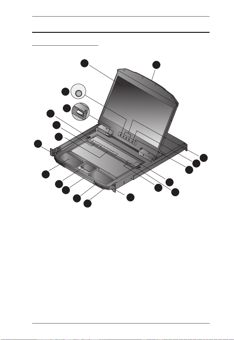
CL3884NW Front View
Chapter 1. Introduction
5
Page 16

CL3884NW User Manual
No. Component Description
1 Upper Handle
with Release Bar
2 LCD Module After sliding the KVM module out, flip up the cover to access
3 LED Illumination
Light Pushbutton
4 LED Illumination
Light
5 Keyboard
Module
Releases
6CPU Port
Selection
Pushbutton /
LEDs
7 Multi-View Mode
& Display Mode
Pushbuttons /
LEDs
8 Keyboard Standard 105-key keyboard
9 Touchpad Standard mouse touchpad
10 Lower Handle
with Release Bar
11 USB Peripheral
Port
12 Power LED Lights green to indicate that the unit is receiving power.
Pull to slide the LCD module out; push to slide it in. See
Opening / Closing the Console, page 21 for sliding the
console in and out.
the LCD monitor by pressing the Handle, see Upper Handle
with Release Bar, page 6.
Press the Exit/Light pushbutton for two seconds to turn the
LED light ON or Off. (Default: Off)
Illuminates the keyboard and touchpad to allow visibility in
low-light conditions.
These catches (one on each side) release the keyboard
module so you can slide it away.
Press the CPU Port Selection Pushbuttons to bring the KVM
focus to the computer attached to the corresponding port.
An orange ON LINE LED lights to indicate that the computer
attached to its corresponding port is up and running. A green
Selected LED lights to indicate that the computer attached to
the corresponding port is selected for KVM control.
In a cascade setup, press a CPU Port Selection Pushbutton
to switch the console display to the corresponding
TM
secondary KVMP
Press and hold CPU Port Selection Pushbuttons 1 and 2
simultaneously for 2 seconds to detect the console
keyboard and mouse again.
Press and hold KVM Port Selection Pushbuttons 3 and 4
simultaneously for 2 seconds to start Auto Scan Mode. See
Auto Scan Mode, page 65, for full details.
Press these pushbuttons to cycle through different display
modes, and multi-view modes for your CL3884NW and the
external console. See Display Modes, page 34, and Display
Mode, page 46 for details.
Pull to slide the keyboard module out. See Opening / Closing
the Console, page 21, for details on sliding the console in and
out.
USB peripherals (printers, scanners, drives etc.) plug into this
port.
Switch.
6
Page 17
Chapter 1. Introduction
2
1 4
3 5 6
No. Component Description
13 Rack Mounting
Brackets
14 Lock LEDs The Num Lock, Caps Lock, Scroll Lock LEDs are located
15 Reset Button Located to the right of the Lock LEDs. Press this recessed
16 Firmware
Upgrade Switch
17 LCD On / Off
Button
18 LCD Control
Buttons
Rack mounting brackets are located at each corner of the unit.
See Standard Rack Mounting, page 11, for details.
here.
switch in with a small object to perform a system reset.
During normal operation and while performing a firmware
upgrade, this switch should be in the NORMAL position. If a
firmware upgrade operation does not complete successfully,
see Upgrade Failed, page 115 for details on how to recover
the situation.
Push this button to turn the LCD monitor on and off. The
button lights when the LCD monitor is off.
Note: The light indicates that only the monitor is off, not the
attached KVM switch.
The buttons to control the position and picture settings of the
LCD display are located here. See page 28, for details.
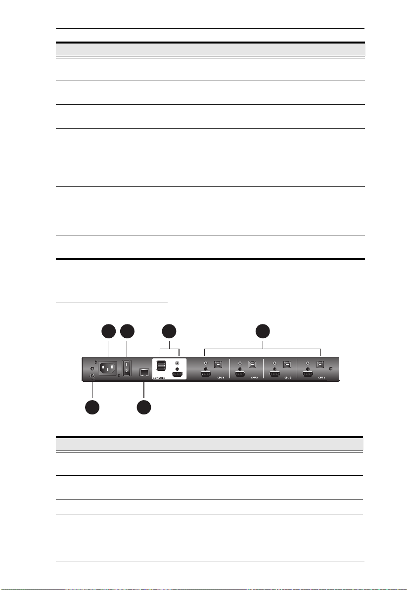
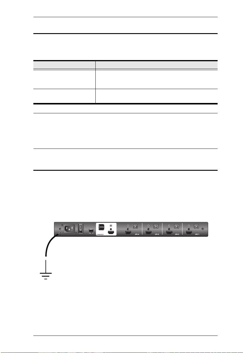
CL3884NW Rear View
No. Component Description
1 Grounding
Terminal
2 Power Socket This is a standard 3-prong AC power socket. The power cord
3 Power Switch This standard rocker switch powers the unit on and off.
4 RS-232 Serial
Port
The grounding wire used to ground the switch attaches here.
from an AC source plugs in here.
You can control the CL3884NW by sending serial commands
through the RS-232 Serial Port. See Chapter 7, RS-232
Operation for details.
7
Page 18

CL3884NW User Manual
No. Component Description
5 External
Console Section
For flexibility and convenience, the CL3884NW supports an
independent, external console. The external console’s USB
keyboard and mouse, HDMI display, and speakers cables
plug in here.
6 KVM Port
Section
The provided KVM Cable Sets (USB, HDMI, and Audio) that
link the CL3884NW to your computers plug in here.
8
Page 19
Hardware Setup
1. Important safety information regarding the placement of this
device is provided on page 117. Please review it before
proceeding.
2. Make sure that power to all the devices you will be connecting
up has been turned off. You must unplug the power cords of any
computers that have the Keyboard Power On function.
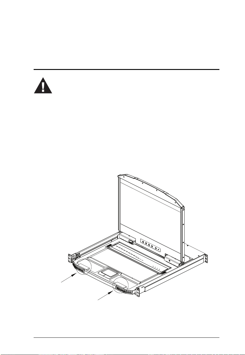
3. CL3884NW packing material has been inserted to protect the
CL3884NW during shipping. Slide the LCD module out (see
Opening / Closing the Console, page 21), until the packing
material is visible. Remove the packing material before
installing the unit, as shown in the diagram below.
Before you Begin
Chapter 2
9
Page 20
CL3884NW User Manual
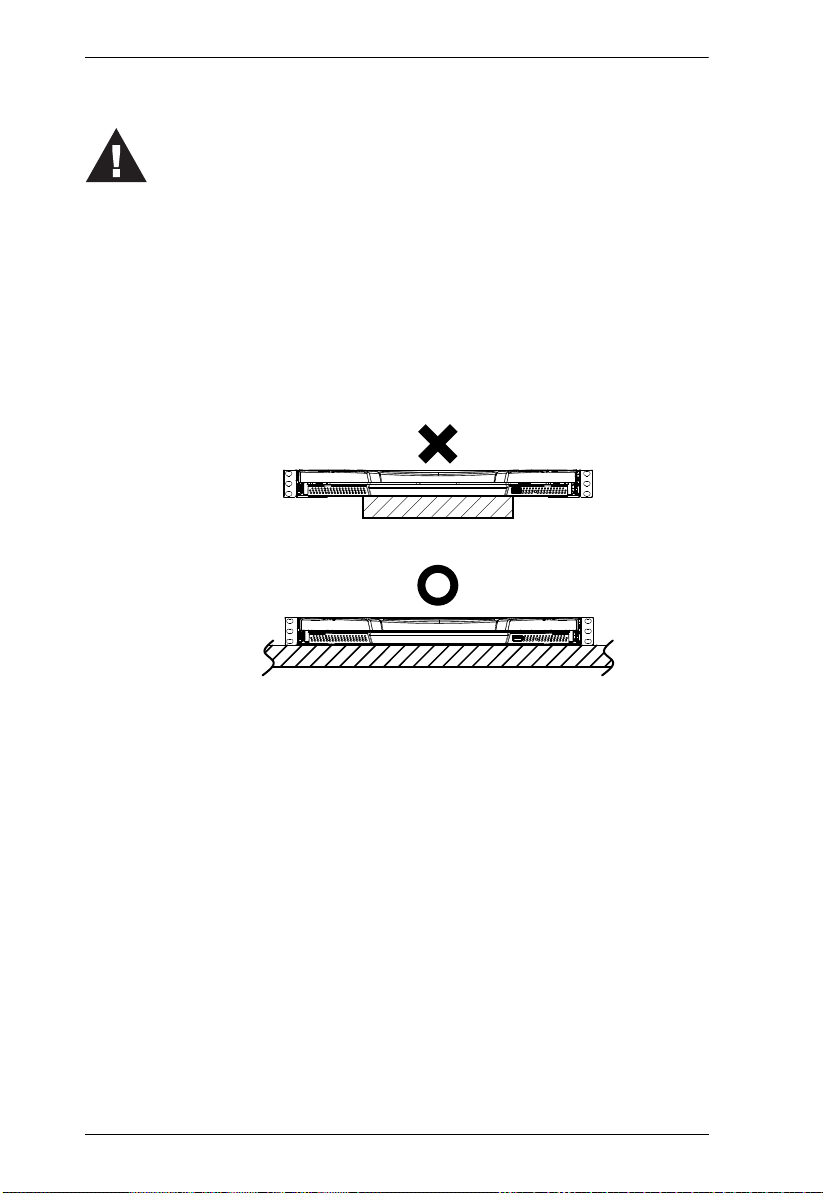
4. The LCD KVM switch is designed for rack mounting. If the
KVM switch is not rack mounted be sure to place it on a
completely flat and firm surface before pulling the device in or
out to prevent damage due to uneven force on the module.
5. To prevent damage to your installation from power surges or
static electricity. It is important that all connected devices are
properly grounded.
Place on Flat Surface
10
Page 21
Chapter 2. Hardware Setup
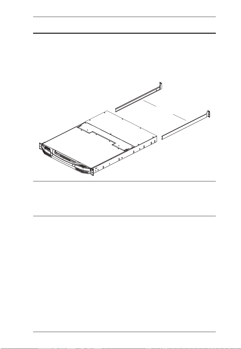
Left & Right L-shaped Brackets
Standard Rack Mounting
A standard rack mounting kit is provided with your CL3884NW and can be
mounted in 1U of rack space. The kit enables the switch to be mounted in rack
with a depth of 58.0
following sections. Below is an image of the parts included with your package
that will be needed for rack installation.
–
80.0 cm. The installation procedures are described in the
Note: It takes two people to mount the console.
The standard rack mounting kit does not include screws or cage
nuts. If you need additional screws or cage nuts, contact your rack
dealer.
11
Page 22
CL3884NW User Manual
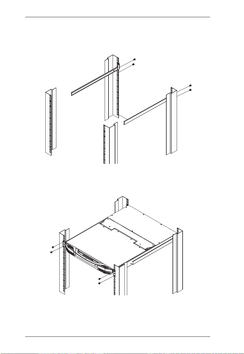
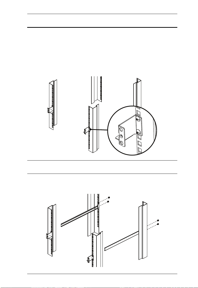
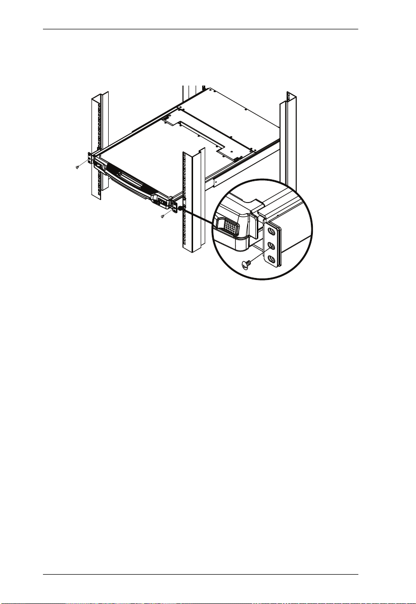
To rack mount the CL3884NW, do the following:
1. Attach the left and right L-shaped brackets to the back of the rack,
installing four screws in the brackets to secure them in place.
2. While one person inserts the unit into place by sliding its left and right side
bars into the left and right L-shaped brackets (on the rack), have a second
person screw the front brackets to the rack.
3. After the front brackets are secured, tighten all the screws.
Allow at least 5.1 cm on each side for proper ventilation, and at least 12.7
cm at the back for the power cord and cable clearance.
12
Page 23
Chapter 2. Hardware Setup
Front-L Brackets Mounting
To have a comfortable and safe posture, install the Front-L Brackets which
provide an extension at the front of the rack to help the unit slide further out
and thus allowing you to tilt the LCD screen more. Instructions to use this
option are shown below:
1. Attach the left and right Front-L brackets to the front of the rack, placing
screws in the tabs to secure them in place.
Note: Rack screws are not provided to mount the unit. We recommend that
you use M5 x P0.8 screws.
2. Attach the left and right L-shaped brackets to the back of the rack,
installing four screws in the tabs to secure them in place.
13
Page 24
CL3884NW User Manual
The CL3800 LCD KVM shown
here is used as a schematic representation
of this step.
3. While one person inserts the unit into place by sliding its left and right side
bars into the left and right L-shaped brackets (on the rack), have a second
person screw the front brackets to the rack.
4. After the front brackets are secured, tighten all the screws.
Allow at least 5.1 cm on each side for proper ventilation, and at least 12.7
cm at the back for the power cord and cable clearance.
14
Page 25
Chapter 2. Hardware Setup
Optional Rack Mount Kits
For convenience and flexibility, optional rack mount kits are available and are
listed in the table below:
Mounting Kit Description
Standard Long Rack Mount
Kit
Easy Installation Rack
Mount Kit
This kit is the long-railed version of your standard
mounting kit that lets you fit your device to racks with
greater depth.
This kit is designed to be easy to install and can be
installed by one person
Note: For more information, visit the product webpage and refer to the
Compatible Accessories.
For detailed installation steps, visit the product webpage and refer
to the Optional Rack Mount Kits Installation Guide.
Grounding
To prevent damage to your installation it is important that all devices are
properly grounded. Use a grounding wire to ground the CL3884NW by
connecting one end of the wire to the grounding terminal, and the other end of
the wire to a suitable grounded object.
15
Page 26
CL3884NW User Manual
1
4
2
5
CL3884NW
(Rear)
3
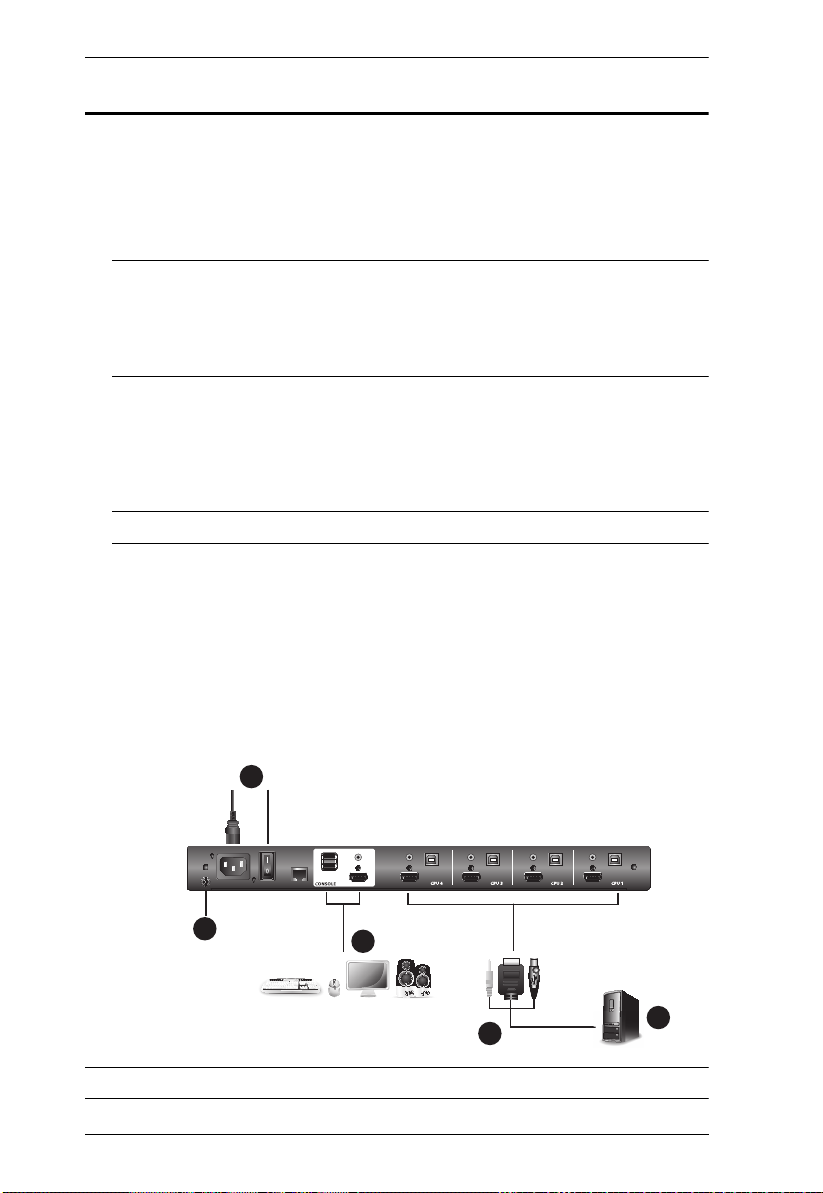
Single Level Installation
In a single level installation, there are no additional switches cascaded from the
first unit. To set up a single level installation do the following:
1. Ground the CL3884NW by connecting one end of a grounding wire to the
grounding terminal and the other end to a suitable grounded object.
Note: 1. Make sure that power has been turned off to all the computers you
will be connecting.
2. Do not omit this step. Proper grounding helps to prevent damage
to the unit from power surges or static electricity.
2. Use the provided KVM cable sets* (as described in the Cables section on
page 4), to connect any available KVM port to the keyboard, video and
mouse ports of the computer you are installing. Refer to the KVM Cable
Installation Diagrams on the following page.
Note: Contact your KVM dealer for ordering information.
3. (Optional) Connect your USB keyboard, USB mouse, 2nd HDMI display,
and speakers into the External Console Section.
4. Plug the power cord into the CL3884NW power socket and into an AC
power source. Turn on the Power Switch of the CL3884NW.
5. Power on the computers.
Single Level Installation Diagram
Note: The numbers in the diagram correspond to the numbered steps above.
16
Page 27
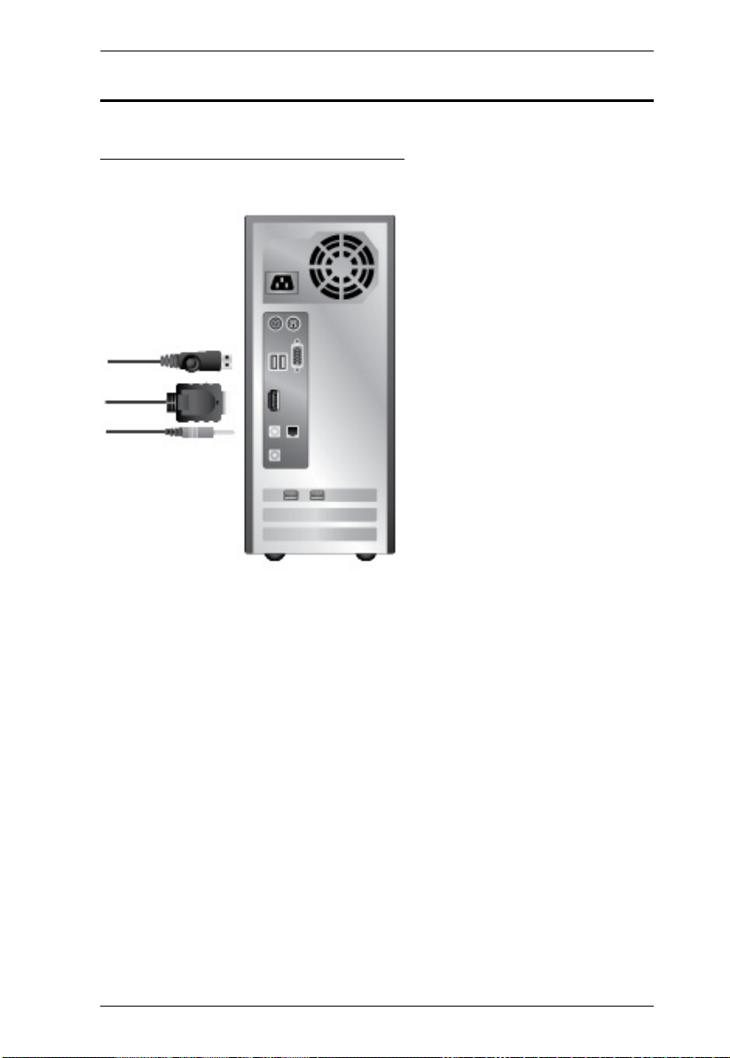
Cable Connection Diagrams
KVM Cable Installation Diagrams
Chapter 2. Hardware Setup
17
Page 28

CL3884NW User Manual
Cascading
To control even more computers, up to 4 additional switches can be cascaded
from the first CL3884NW (see the Appendix for a list of compatible ATEN
switches). As many as 16 computers can be controlled from a single console in
a complete cascade installation. Tables showing the relation between the number
of computers and the number of switches needed to control them are provided
on page 123 in the Appendix.
Note: The CL3884NW can only be installed as the first switch in a two level
installation as its LCD, keyboard and mouse are used as the console and
all second level switches require an external console port to be
cascaded.
To set up a cascade installation, make sure that the power to all devices has
been turned off, and then do the following:
1. Ground the CL3884NW by connecting one end of a grounding wire to the
grounding terminal and the other end to a suitable grounded object.
Note: Do not omit this step. Proper grounding helps to prevent damage to
the unit from power surges or static electricity.
2. Connect the console ports of a secondary CM1164A / CM1284 to any
available KVM Port on the primary CL3884NW using the provided KVM
cables. To cascade another CM1164A / CM1284, repeat this step.
Note: 1. If the CM1164A is connected for cascade, make sure to use a DVI
to HDMI connector.
2. If the CM1284 is connected for cascade, make sure to connect the
Console HDMI Port 1 of the secondary CM1284 instead of its
Port 2 to the primary CL3884NW to be able to display multi-view
modes.
3. Connect the secondary CM1164A / CM1284 units with computers / video
sources. For detailed steps, see.
Note: Make sure the computers and devices that the CM1164A / CM1284
connects to are also properly grounded.
4. (Optional) Connect the primary CL3884NW with a USB keyboard, USB
mouse, and speakers.
18
Page 29
Chapter 2. Hardware Setup
1
4
2
5
CL3884NW
(Rear)
3
(4X4 multi-view)
5
13
7
15
2
10
4
12
1
9
3
11
6
8
14
16
Primary Unit
CM1164A
CM1284
Secondary Units
CM1164A
CM1284
2
2 2
3 3 3
PC1PC2PC3PC4
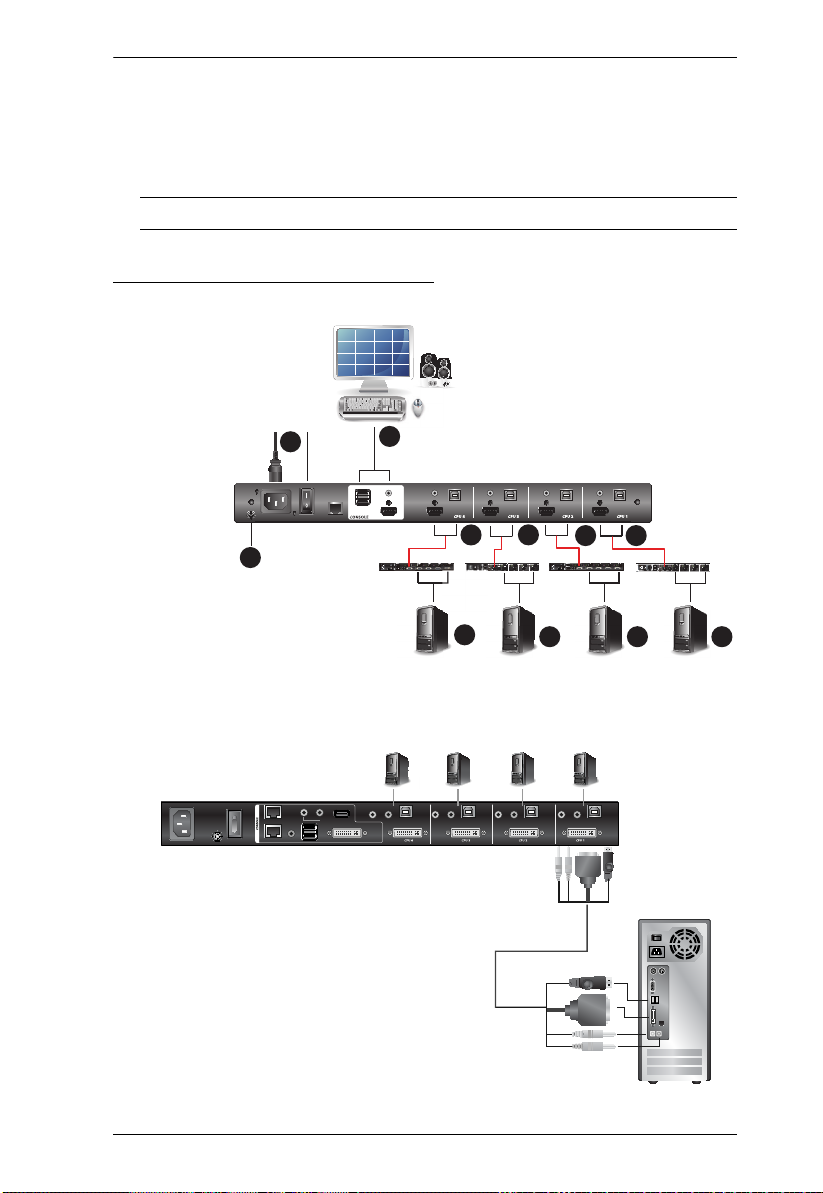
5. The Power On sequence requires that all secondary units be powered on
first. After they are all on, the master unit must be powered on next. Only
after all the switches have been powered on in this sequence, can the
computers be powered on.
Note: Remember to turn on the Power Switch on the CL3884NW.
Two Level Installation Diagram
Connecting the CM1164A with Computers and Video Sources
19
Page 30
CL3884NW User Manual
QD2QD3QD4QD5
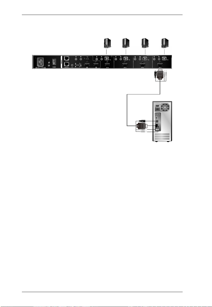
Connecting the CM1284 with Computers and Video Sources
20
Page 31

Chapter 3
Upper Release BarUpper Release Bar
Basic Operation
Opening / Closing the Console
The CL3884NW’s console consists of two modules: an 18.5” LCD display
module located under the top cover, and a keyboard / touch pad module below
the LCD module. The modules can either slide together, or independently. This
allows you to have the LCD display available for viewing while the keyboard
/ touch pad module is conveniently out of the way when not in use.
Note: As a safety precaution, to keep the console from accidentally sliding
out, the console is locked into the in position. Before you can pull the
console module out, you must release it by pulling the Release Bar on
the unit's front panel toward the center of the switch.
To slide the console module out, do the following:
1. Use the Upper Release Bar Handle to pull the Panel Module straight out.
21
Page 32

CL3884NW User Manual
2. Pulling, slide the Panel Module all the way out until it automatically clicks
in place.
3. Raise the LCD Module all the way back to expose the LCD screen.
22
Page 33

Chapter 3. Basic Operation
Lower Release Bar
4. Use the Lower Release Bar Handle to pull the Keyboard Module straight
out until it clicks in place.
Lower Release Bar
5. To independently retract they keyboard into the rack, slide both Keyboard
Module Releases and push the Keyboard Module all the way in.
23
Page 34

CL3884NW User Manual
6. Slide the keyboard in until its completely inserted into the rack.
7. To close the LCD screen, lower the LCD Module until it lies flat and slide
it back in.
24
Page 35

Operating Precautions
The maximum load bearing capacity of the keyboard module is 30kg.
Failure to heed the information below can result in damage to the
keyboard module.
Chapter 3. Basic Operation
Right!
Rest your hands and arms lightly on the
keyboard module as you work.
Wrong!
DO NOT lean your body weight on the
keyboard module.
DO NOT place heavy objects on the
keyboard module.
25
Page 36

CL3884NW User Manual
Powering Off and Restarting
If it becomes necessary to power off the CL3884NW, do the following before
restarting it:
1. Shut down all the computers that are attached to the CL3884NW.
Note: Unplug the power cords of any computers that have the Keyboard
Power On function. Otherwise, the CL3884NW will still receive
power from the computers.
2. Unplug the CL3884NW from its power source.
3. Wait 10 seconds, then plug the CL3884NW back in.
4. After the CL3884NW has started and ascertained its station ID, power on
the computers.
Note: If you have shut down more than one station, power up the highest
station first and work your way down to the lowest one.
Hot Plugging
The CL3884NW supports hot plugging – components can be removed and
added back into the installation by unplugging their cables from the ports
without the need to shut the unit down. In order for hot plugging to work
properly, the procedures described below must be followed:
Hot Plugging KVM Ports
In order for the OSD menus to correspond to KVM port changes, you must
manually reconfigure the OSD to reflect the new port information. See page 57
for details.
Note: If the computer's operating system does not support hot plugging, this
function may not work properly.
26
Page 37

Chapter 3. Basic Operation
LCD OSD Configuration
The LCD Buttons
The LCD OSD allows you to set up and configure the LCD display. Four
buttons are used to perform the configuration, as described in the table, below:
Button Function
MENU
EXIT / LIGHT
LCD On / Off
Button
When you have not entered the LCD OSD Menu function,
pressing this button invokes the Menu function, and brings up
the Main Menu.
When you have entered the LCD OSD Menu function, and
have reached a setting choice with the navigation buttons,
pressing this button brings up its adjustment screen.
When navigating through the menus, this button moves you Right
or Up. When making an adjustment, it increases the value.
When navigating through the menus, this button moves you Left
or Down. When making an adjustment, it decreases the value.
When you have not entered the LCD OSD Menu function,
pressing this button performs an auto adjustment. An auto
adjustment automatically configures all the settings for the LCD
panel to what the OSD considers their optimum values to be.
When you have entered the LCD OSD Menu function, pressing
this button exits the current menu and returns you to the
previous menu. Use it to leave an adjustment menu when you
are satisfied with the adjustment you made.
When you are at the Main Menu, pressing this button exits the
LCD OSD.
Push this button to turn the LCD monitor on and off. The button
lights when the LCD monitor is off.
Note:The light only indicates that the monitor is off, not the
attached KVM switch.
27
Page 38

CL3884NW User Manual
LCD Adjustment Settings
An explanation of the LCD OSD adjustment settings is given in the table below:
Setting Explanation
Brightness Adjusts the background black level of the screen image.
Contrast Adjusts the foreground white level of the screen image.
Color Temperature Adjusts the color quality of the display. You can adjust the
Language Selects the language that the OSD displays its menus in.
OSD Duration Lets you set the amount of time the OSD displays on the
Reset Resets the adjustments on all menus and submenus to
Note: As an alternative to manually adjusting the LCD settings, you can have
the LCD auto-adjusted for optimum display by pressing the Exit button.
See EXIT / LIGHT, page 27.
warmth value, color balance, etc. The Adjust Color
selection has a further submenu that lets you fine tune the
RGB values.
screen. If there is no input for the amount of time you
choose, the OSD display turns off.
their factory default settings.
Note:The Language setting does not return to the factory default,
but remains at the one that you have set it to.
28
Page 39

Chapter 3. Basic Operation
This computer is connected to Port 1
This computer is named PC 1
Click to extend the window to full screen
Identifying the Source Device
You can identify the source connected to the CL3884NW from the channel
information at the top-left corner in the screen:
Note: To hide this information, disable the Channel Info setting (Display >
Channel Info) from the OSD Menu.
29
Page 40

CL3884NW User Manual
Port ID Numbering & Port Selection
Port ID Numbering
Port ID number: This number is assigned according to the port that the
computer is connected to on the rear of the CL3884NW. For example, a
computer connected to port 1 is assigned port ID 1.
Device name: By default, the computer connected to port 1 is named PC 1, the
computer connected to port 2 is named PC 2, and so forth. To change the device
name, go to System Settings > Port Configuration, see Port Configuration,
page 57 for details.
Port Selection
You can directly access any computer on any level of the installation by
specifying the Port ID that the computer is connected to.
Using the CPU Selection Pushbuttons (see CPU Port Selection
Pushbutton / LEDs, page 6).
Using the OSD (see OSD Operation, page 47).
Using the Hotkey Port Selection method (see Keyboard Port Operation,
page 63).
Using the RS-232 Commands (see RS-232 Operation, page 75).
If you connect a KVM switch (CM1164A / CM1284) to the CL3884NW, Port
ID numbering and Port Selection follow the method used by the connected
KVM switch. Consult your KVM switch’s user manual for details.
Note: In a cascade setup, a port ID number of “1-3” indicates that the video
source comes from the third port of the secondary CM1164A / CM1284
connected to port 1 of the primary CL3884NW.
30
Page 41

Chapter 3. Basic Operation
Switching
The CL3884NW supports group switching and independent switching:
Group switching: switches to the KVM (keyboard, video, mouse), audio,
and USB sources of one computer.
Independent switching: switches to KVM (keyboard, video, mouse),
stereo audio, and USB sources independently, on different computers. This
allows you to work on one computer (KVM), access the audio on another
(stereo audio), and connect to peripheral devices on a third (USB).
Manual Port Switching
Use the CPU Port Selection Pushbuttons to switch KVM focus to any port on
the installation. Please see CPU Port Selection Pushbutton / LEDs, page 6 for
details.
Hotkey Switching
You can switch to a computer using hotkeys from the keyboard.
To switch to computer 1, do the following:
1. Press and hold down [Num Lock].
2. Press and release [-].
3. Release [Num Lock].
4. Press [1].
5. Press [Enter].
Repeat the steps using Port ID (1, 2, 3, 4) in step 4 to switch to the computer
connected to that port. For more hotkeys, see Keyboard Port Operation,
page 63.
31
Page 42

CL3884NW User Manual
OSD Switching
You can switch to a computer by accessing the Quick Access Toolbar with the
console mouse.
To switch computers with the OSD, do the following:
1. Move the cursor to the top of the OSD to display the Quick Access Bar.
2. From the Quick Access Toolbar, click
message “Press
32
to exit edit mode” appears.
to activate the editor mode. The
Page 43

Chapter 3. Basic Operation
3. Click the port number at the top-left corner to open drop-down list, and
then select a computer: 1, 2, 3, or 4. The display is immediately switched
to the selected computer.
4. When you finish configuring, click
to end the editor mode.
Boundless Switching
Boundless Switching allows the CL3884NW to switch computers by sliding
the mouse cursor across the screen borders. The mouse cursor can be moved
up, down, left, or right– off one screen and onto another to switch keyboard/
mouse control to the adjacent computer. The audio and USB hub focus is also
switched to the new computer. The mouse cursor can also move across displays
even when they are cascaded.
Before using the Boundless Switching, the users must turn off mouse
acceleration in the operation system. The Boundless Switching can only work
with either the touch pad or the USB mouse connected to the external console.
The default setting is touch pad, you can toggle between the two to perform the
boundless switching, see Hotkey Summary Table, page 68 for details.
33
Page 44

CL3884NW User Manual
Display Modes
You can view multiple computers connected to the CL3884NW on the same
screen, in different layout by setting the display mode. This section introduces
you to different display modes, and ways of switching to them.
Full Screen
A full-screen view displays one computer in full extension.
Method Action Description
CPU Port
Selection
Pushbuttons
Mouse
Wheel
Quick
Access
Toolbar
34
Press a CPU Port Selection
Pushbutton.
In any PiP mode, move the cursor
to the window you wish to extend,
and double-click the mouse wheel.
Note: This function is disabled by
default. To use this function, enable
the Advanced > Mouse Wheel
Switching function from the OSD
Menu.
Move the mouse to the top center of
the OSD to display the Quick
Access Toolbar, and then select
from the Quick Access Toolbar.
Note: Hardware Cursor Mode must
be enabled, see The OSD Menu,
page 51.
N/A
Page 45

Chapter 3. Basic Operation
Method Action Description
Hotkey Switch to a particular port to display
the computer in full screen.
See Invoke Hotkey Mode, page 63
for hotkey instructions.
OSD Menu
In the OSD, click from the Quick
Access Toolbar, go to Display >
Multiview Mode, and then select
Single.
Note: You may need a password to
access the OSD Menu. For details,
see Password Protection, page 51.
35
Page 46

CL3884NW User Manual
Quad View
A quad view displays four computers on the monitor in equal sized windows.
Method Action Description
Multi-View
Mode &
Display
Mode
Pushbuttons
/ LEDs
Quick
Access
Toolbar
Hotkey Enter the illustrated hotkeys.
Press this pushbutton to display
quad view mode.
Move the mouse to the top center of
the OSD to display the Quick
Access Toolbar, and then select
from the Quick Access Toolbar.
Note: Hardware Cursor Mode must
be enabled, see The OSD Menu,
page 51.
See Invoke Hotkey Mode, page 63
for hotkey instructions.
OSD Menu
36
In the OSD, click from the Quick
Access Toolbar, go to Display >
Multiview Mode, and then select
Quad.
Note: You may need a password to
access the OSD Menu. For details,
see Password Protection, page 51.
Page 47

Chapter 3. Basic Operation
Picture in Picture - Dual
A dual PiP view shows 2 computers on the monitor with one as the main
display, and the other overlapping the main display in an inset window.
Method Action Description
Multi-View
Mode &
Display
Mode
Pushbuttons
/ LEDs
Quick
Access
Toolbar
Hotkey Enter the illustrated hotkeys.
Press this pushbutton to display
picture in picture dual mode.
Move the mouse to the top center
of the OSD to display the Quick
Access Toolbar, and then select
from the Quick Access Toolbar.
Note: Hardware Cursor Mode
must be enabled, see The OSD
Menu, page 51.
See Invoke Hotkey Mode,
page 63 for hotkey instructions.
OSD Menu
In the OSD, click from the
Quick Access Toolbar, go to
Display > Multiview Mode, and
then select PiP2.
Note: You may need a password
to access the OSD Menu. For
details, see Password Protection,
page 51.
37
Page 48

CL3884NW User Manual
Picture in Picture - Triple
A triple PiP view has 3 computers on the monitor with one computer as the
main display and the other two overlapping the main display in inset windows.
Method Action Description
Multi-View
Mode &
Display
Mode
Pushbuttons
/ LEDs
Quick
Access
Toolbar
Hotkey Enter the illustrated hotkeys.
Press this pushbutton to display
picture in picture triple mode.
Move the mouse to the top center
of the OSD to display the Quick
Access Toolbar, and then select
from the Quick Access Toolbar.
Note: Hardware Cursor Mode must
be enabled, see The OSD Menu,
page 51.
See Invoke Hotkey Mode, page 63
for hotkey instructions.
OSD Menu
38
In the OSD, click from the
Quick Access Toolbar, go to
Display > Multiview Mode, and
then select PiP3.
Note: You may need a password to
access the OSD Menu. For details,
see Password Protection, page 51.
Page 49

Chapter 3. Basic Operation
Picture in Picture - Quad
A quad PiP view has 4 computers on the monitor with one computer as the
main display and the other three overlapping the main display in inset
windows.
Method Action Description
Multi-View
Mode &
Display Mode
Pushbuttons /
LEDs
Quick Access
Toolbar
Hotkey See Invoke Hotkey Mode, page 63
Press this pushbutton to display
picture in picture quad mode.
Move the mouse to the top center
of the OSD to display the Quick
Access Toolbar, and then select
from the Quick Access Toolbar.
Note: Hardware Cursor Mode
must be enabled, see The OSD
Menu, page 51.
for hotkey instructions.
OSD Menu
In the OSD, click from the
Quick Access Toolbar, go to
Display > Multiview Mode, and
then select PiP4.
Note: You may need a password
to access the OSD Menu. For
details, see Password Protection,
page 51.
39
Page 50

CL3884NW User Manual
Picture on Picture
A picture-on-picture (PoP) view shows 4 computers in separate windows on
the monitor. In editor mode, you can use the console mouse to resize and
re-position each window on the screen.
Method Action Description
Quick Access
Toolbar
Hotkey Enter the illustrated hotkeys.
Move the mouse to the top
center of the OSD to display
the Quick Access Toolbar, and
then select from the Quick
Access Toolbar.
Note: Hardware Cursor Mode
must be enabled, see The OSD
Menu, page 51.
See Invoke Hotkey Mode,
page 63 for hotkey instructions.
OSD Menu
40
In the OSD, click from the
Quick Access Toolbar, go to
Display > Multiview Mode,
and then select PoP.
Note: You may need a
password to access the OSD
Menu. For details, see
Password Protection, page 51.
Page 51

Chapter 3. Basic Operation
Picture by Picture - Dual
The picture-by-picture (dual) view displays 2 computers side by side on the
monitor.
Method Action Description
Quick Access
Toolbar
Hotkey Enter the illustrated hotkeys.
Move the mouse to the top
center of the OSD to display
the Quick Access Toolbar,
and then select from the
Quick Access Toolbar.
Note: Hardware Cursor
Mode must be enabled, see
The OSD Menu, page 51.
See Invoke Hotkey Mode,
page 63 for hotkey
instructions.
OSD Menu
In the OSD, click from the
Quick Access Toolbar, go to
Display > Multiview Mode,
and then select PbP2.
Note: You may need a
password to access the OSD
Menu. For details, see
Password Protection,
page 51.
41
Page 52

CL3884NW User Manual
Picture by Picture - Triple
The picture-by-picture (triple) view displays 3 computers side by side on the
monitor.
Method Action Description
Quick Access
Toolbar
Hotkey Enter the illustrated hotkeys.
Move the mouse to the top
center of the OSD to display
the Quick Access Toolbar, and
then select from the Quick
Access Toolbar.
Note: Hardware Cursor Mode
must be enabled, see The
OSD Menu, page 51.
See Invoke Hotkey Mode,
page 63 for hotkey instructions.
OSD Menu
42
In the OSD, click from the
Quick Access Toolbar, go to
Display > Multiview Mode,
and then select PbP3.
Note: You may need a
password to access the OSD
Menu. For details, see
Password Protection, page 51.
Page 53

Chapter 3. Basic Operation
Picture by Picture - Quad
The picture-by-picture (quad) view displays 4 computers side by side on the
monitor.
Method Action Description
Quick Access
Toolbar
Hotkey Enter the illustrated hotkeys.
Move the mouse to the top
center of the OSD to display
the Quick Access Toolbar, and
then select from the Quick
Access Toolbar.
Note: Hardware Cursor Mode
must be enabled, see The OSD
Menu, page 51.
See Invoke Hotkey Mode,
page 63 for hotkey instructions.
OSD Menu
In the OSD, click from the
Quick Access Toolbar, go to
Display > Multiview Mode,
and then select PbP4.
Note: You may need a
password to access the OSD
Menu. For details, see
Password Protection, page 51.
43
Page 54

CL3884NW User Manual
Preset Configuration
You can save up to 4 sets of configuration, including the display mode, source
assignment, division sizes, division locations, and KVM/Audio/USB focus
status to easily toggle between different display configurations.
To save a configuration, follow the steps below.
1. Configure the display settings as required.
2. Move the console mouse to the top of the screen. The Quick Access
Toolbar appears.
3. Click and select a preset (Fn) to save the current configuration.
4. To apply a preset configuration, use any of the following methods.
Method Action Description
Quick Access
Toolbar
Hotkey Enter the illustrated hotkeys.
44
Move mouse to top center of the
OSD and then select from the Quick
Access Toolbar.
Note: Hardware Cursor Mode must
be enabled, see The OSD Menu,
page 51.
See Invoke Hotkey Mode, page 63
for hotkey instructions.
Page 55

Chapter 3. Basic Operation
Method Action Description
OSD Menu
In the OSD, click from the Quick
Access Toolbar, go to Display >
Save to Fn, and then select your
desired preset configuration (Fn1,
Fn2, Fn3, and Fn4).
Note: You may need a password to
access the OSD Menu. For details,
see Password Protection, page 51.
45
Page 56

CL3884NW User Manual
Display Mode
There are three display modes for your CL3884NW LCD (local console), and
the external console.
Multi-view with Full-screen
Full-screen with Multi-view
Multi-view with Multi-view
Note: By default, the CL3884NWis set to display Multi-view on the LCD
(local console), and Full-screen on the external console.
To Change the display mode, use the following methods.
Method Action Description
Multi-View
Mode &
Display Mode
Pushbuttons
/ LEDs
Hotkey Enter the illustrated hotkeys.
Press these pushbuttons to display different display mode from
Multi-vew with Full-screen, Fullscreen with Multi-vew, or Multiview with Multi-view.
See Invoke Hotkey Mode,
page 63 for hotkey instructions.
OSD Menu
46
In the OSD, click from the
Quick Access Toolbar, go to
Display > Local Console or
External Console, and then
select a display mode.
Note: You may need a
password to access the OSD
Menu. For details, see
Password Protection, page 51.
Page 57

Chapter 4
OSD Operation
OSD Overview
The on-screen display (OSD) is a mouse and keyboard enabled, menu driven
method to handle computer control and switching operations. All procedures
start from the OSD main screen.
The CL3884NW can be operated and configured via the following OSD
components:
Quick Access Toolbar: This toolbar provides quick access for changing
the display mode, saving display templates, and customizing division
sizes. For details, see The Quick Access Toolbar, page 48.
OSD Menu: This contains controls for all system settings. For details, see
The OSD Menu, page 51.
OSD Login
The OSD incorporates an one level password system. Before the OSD main
screen displays, a login screen appears requiring a password.
If this is the first time you are using the OSD, or if the password function has
not been set, use the default password to login. The OSD main screen will
display under administrator mode. In this mode, you have administrator
privileges, with access to all administrator and user functions, and can set up
operations (including password authorization) as you like.
If the password function has been set, you must provide an appropriate
administrator/user password in order to access the OSD.
Dedicated Invocation Key
A dedicated key is provided on the keyboard module to make it easy to invoke
the OSD (as shown in the diagram below):
Note: Press once to invoke the feature; press again to exit.
47
Page 58

CL3884NW User Manual
The Quick Access Toolbar
You can use the Quick Access Toolbar to conveniently switch display modes,
customize window size and location via the editor mode, and apply and save
display templates.
To display the Quick Access Toolbar, move the console mouse to the top of the
scree. The Quick Access Toolbar provides the following controls:
: Click an icon to apply the display mode.
: Click this icon to enable the editor mode to allow you to assign source
to a particular channel and resize inset windows.
: Click a Function icon to apply the selected display template.
: Click this icon to save the current display configuration to a display
template.
: Click this icon to open the OSD Menu. For details, see The OSD
Menu, page 51.
Note: To change the display position, go to Display > Toolbar Position in
the OSD Menu.
48
Page 59

Chapter 4. OSD Operation
The Editor Mode
Use the editor mode to customize the source display. You can resize windows,
change the display source, or relocate windows. To enable the editor mode,
follow the steps below.
1. Make sure the following functions are enabled to allow console mouse to
operate. For details, see The OSD Menu, page 51.
Hardware Cursor
Mouse Emulation
2. Move the console mouse to the top of the screen to display the Quick
Access Toolbar.
3. Click from the Quick Access Tool. A Press ““ to exit edit mode
message appears to indicate that the editor mode is enabled.
49
Page 60

CL3884NW User Manual
4. Configure and adjust the display as required. You can do the following
when the editor mode is enabled:
Function Action
Change the display mode
Apply a preset configuration Click an Fn icon from the Quick Access Toolbar. For
Swap locations of video
sources in quad mode
Resize windows Click on a window, move the cursor to a corner of
Relocate windows Click and hold on a window to drag it to a desired
Set windows to the front or
the back
Reset
Click a display mode from the Quick Access
Toolbar.
Click to display the window in full screen.
more information, see Preset Configuration,
page 44.
Click the port number at the top left corner and
select a port.
the window, and drag the corner to resize the
window.
location on the screen.
When two windows overlap, you can configure
which one appears on top of the other. To bring a
window on top of the other, click the window, and
then click . Click to send the selected
window to the back.
Click to reset all the port location and size back
to default settings.
Note: When the editor mode is enabled, the OSD Menu will not be
accessible and the hotkeys functionality will be disabled.
5. When you finish configuring, click
50
to quit the editor mode.
Page 61

Chapter 4. OSD Operation
The OSD Menu
The OSD Menu contains all the display settings and system settings for the
CL3884NW. To access the OSD Menu, use any of the following methods:
Tap [Scroll Lock] twice on the console keyboard
Move the console mouse to the top center of the OSD to display the Quick
Access Toolbar, and then click .
Note: The hotkey to activate the OSD can be changed to the Ctrl key. See
see Menu Hotkey, page 54.
Password Protection
By default, the CL3884NW’s OSD Menu is protected by password and is
locked if the OSD Menu has not been operated for 30 seconds. This i s to se c ure
the advanced settings, the OSD Menu, from general operations using the Quick
Access Toolbar, including:
Change the display mode
Switch sources
Resize and relocate the windows in any multiview mode
Change the display order of the PoP mode
Save configurations
Apply preset configurations
Swap ports
Re-assign channel position in any multiview mode
Note: 1. To disable password protection or to change the password, go to
Password > Password Protection in the OSD Menu.
2. To configure how long the CL3884NW logs out from the OSD
Menu, go to General > Logout Timeout in the OSD Menu.
51
Page 62

CL3884NW User Manual
OSD Main Screen
You can close the OSD Menu by pressing [Esc] or Spacebar.
[Esc] returns to the previous page.
When you invoke the OSD, a screen similar to the one below appears:
OSD functions are used to configure and control the OSD. For example, you
can rapidly switch to any port, scan selected ports, limit the list you wish to
view, designate a port as a quick view port, create or edit a port name, or make
OSD setting adjustments. The following settings are described below. Default
settings are indicated in bold.
52
Page 63

Chapter 4. OSD Operation
General
Setting Options Description
General
Note: Default settings are indicated in bold.
OSD Language English / Chinese TW /
Chinese CN /
Japanese, Korean /
French / German /
Italian / Russian
Pushbutton Lock Enable / Disable Locks or unlocks the CL3884NW’s
Logout Timeout Never / 10s / 30s / 60s
/ 5 mins / 10 mins
Active Beeper Enable / Disable
Toolbar Position Top / Bottom Sets the position of the Quick Access
Sets the language for the OSD Menu.
panel pushbuttons.
Sets how long the CL3884NW waits
after the last input or
RS-232 command before automatically
logging out from the OSD Menu or
closing an RS-232 session.
Enable this function for CL3884NW to
sound a beep to indicate and confirm
user configuration.
Toolbar.
53
Page 64

CL3884NW User Manual
Setting Options Description
Keyboard Language Auto Detect / English Auto detects the language of the local
keyboard. For these options to be
available, make sure to enable
Keyboard Emulation in the OSD Menu.
Hardware Cursor Enable / Disable
Enable this function to allow the use of
console mouse to customize division
sizes, shift between divisions, and
display the Quick Access Toolbar. The
Channel Editor provides a way to
change display modes and other
settings with the mouse and an onscreen control panel.
HSM [Num][-] / [Ctrl][F12] Defines the hotkey combination for
enabling the Hotkey Setting Mode
(HSM).
Menu Hotkey Scroll*2 / Ctrl*2 Sets the hotkey combination for
opening the OSD.
Broadcast Mode Disable / Enable Enable this function to seamlessly
perform operations simultaneously on
all computers, such as software
installation and upgrades, system-wide
shutdown, and more.
54
Page 65

Chapter 4. OSD Operation
Display
Setting Options Description
Display
Note: Default settings are indicated in bold.
Channel Info Enable / Disable Enable this setting to display port ID
Multiview Mode Single / Quad / PiP2 /
PiP3 / PiP4 / PoP /
PbP1 / PbP2 / PbP3 /
Fn1 / Fn2 / Fn3 / Fn4
Channel 1 Port 1 / Port 2 / Port 3 /
Port 4 Sets the source assignment for each
Channel 2 Port 1 / Port 2 / Port 3 /
Port 4
Channel 3 Port 1 / Port 2 / Port 3 /
Port 4
Channel 4 Port 1 / Port 2 / Port 3 /
Port 4
Save to Fn Fn1 / Fn2 / Fn3 / Fn4 Saves the view mode settings to the
numbers and device names.
Sets or changes the display mode for
the CL3884NW. For details about each
display mode, see Display Modes,
page 34.
channel. For example, if you select
Port 2 for Channel 1, port 2 source will
be displayed on Channel 1, and port 1
source will be displayed at Channel 2.
selected Function mode.
55
Page 66

CL3884NW User Manual
Setting Options Description
Local Console Multiview / Follow
Cursor / Port 1 / Port 2 /
Port 3 / Port 4
External Console Multiview / Follow
Cursor / Port 1 / Port 2
/ Port 3 / Port 4
Transparency Enable / Disable Enable this setting to make the inset
Sets the local console operation to
work on Multiview, port 1, port 2, port 3,
port 4, or follow cursor.
Sets the external console operation to
work on Multiview, port 1, port 2, port 3,
port 4, or follow cursor.
window(s) of a PiP display semitransparent.
Note: This setting only applies to the
built-in PiP2, PiP3, and PiP4 modes.
A warning message appears if both of the Local Console and External Console
are set to full screen operation.
56
Page 67

Chapter 4. OSD Operation
Port Configuration
Setting Options Description
Port Configuration
Note: Default settings are indicated in bold.
Port 1 Name PC1 Type to name the computers
Port 2 Name PC2
Port 3 Name PC3
Port 4 Name PC4
Port 1 OS Win / Mac / SUN / SPC
Port 2 OS Win / Mac / SUN / SPC
Port 3 OS Win / Mac / SUN / SPC
Port 4 OS Win / Mac / SUN / SPC
connected to port 1 / port 2 / port 3 /
port 4 on the CL3884NW. The
CL3884NW only supports English
characters of upper and lower cases,
numbers, hyphens, and underscores.
Defines the operating system for each
of the connected computers.
57
Page 68

CL3884NW User Manual
Advanced
Setting Options Description
Advanced
Note: Default settings are indicated in bold.
Expansion Cascade Sets the CL3884NW’s deployment to
Auto Scan Disable / Enable Enable this function to have the
Auto Scan Duration 5s / 10s / 15s / 30s /
60s / 90s
cascade.
Note: Hardware Cursor Mode must be
enabled, see The OSD Menu, page 51.
CL3884NW cycle from port to port at
the defined Auto Scan Duration. This
gives users an automated way of
viewing all the computers connected to
the ports.c
Double-click the mouse wheel to switch
to the next port.
This setting is only available when Auto
Scan is enabled. Sets the duration that
a port has KVM focus before the focus
switches to the next port.
58
Page 69

Chapter 4. OSD Operation
Setting Options Description
Auto Scan Mode Cycle / Powered-on PCThis setting is only available when Auto
Scan is enabled.
Cycle: Sets the Auto Scan to cycle
through all computers.
Powered on: Sets the Auto Scan to
only scan powered on computers.
EDID Mode Display A / Display B /
Remix / FHD
Keyboard Emulation Enable / Disable Enable keyboard emulation to allow for
Mouse Wheel
Switching
Power On Detection Enable / Disable Enable this function to have the
Enable / Disable Enable this function to allow the mouse
Display A (local console) / Display
B (external console): This mode
sends the EDID of the selected
display (Display A or DisplayB) to
all connected sources.
Note: When an error occurs and
the video can not be displayed
using the specified EDID mode, the
CL3884NW will automatically
default the EDID mode to ATEN
Default.
Remix: This mode sends the
optimum EDID to all connected
displays.
FHD: This mode sends ATENpredefined EDID (1920 x 1080
@60Hz) to the connected sources.
error-free booting and hotkey
functionality.
Note:
PC keyboard combinations
emulate Sun/Mac keyboards.
Sun/Mac keyboards only work with
their own computers.
wheel to switch to the next port when it
is clicked twice.
Note: This function applies to 3-key
USB wheel mice only.
CL3884NW switch to the next
powered-on computer when a
computer that has KVM focus is
powered off.
59
Page 70

CL3884NW User Manual
Setting Options Description
Window Frame Disable / 3 Secs / 5
Secs / 10 Secs / Always
on
Enable this function to allow a window
frame to indicate which computer that it
currently has the focus.
Password
Setting Options Description
Password
Note: Default settings are indicated in bold.
Password Protection Enable / Disable Enable this function to password
Change Password Enable / Disable Enable this function to change the login
60
protect access to the OSD Menu. The
default password is password.
password for the OSD Menu. This
setting is only available when
Password Protection is enabled.
Note: The password is case-sensitive
and only supports English alphabets
and/or numeric characters.
Page 71

Chapter 4. OSD Operation
Maintenance
Setting Options Description
Maintenance
Note: Default settings are indicated in bold.
Firmware Upgrades Yes / Cancel Select Yes to perform a firmware
upgrade. For details about firmware
upgrades, see The Firmware Upgrade
Utility, page 107.
Save Configuration Profile 1 / Profile 2 /
Profile 3 / Profile 4
Load Configuration Profile 1 / Profile 2 /
Profile 3 / Profile 4
Reset to Default Yes / Cancel Select Yes to set the CL3884NW to
MFG No. Read-only information Displays the manufacturing code of the
EXT VER Read-only information Displays the version of the CL3884NW.
Select an option to back up the current
OSD configuration.
Select an option load a previously
backed up OSD configuration.
default.
CL3884NW.
61
Page 72

CL3884NW User Manual
Manufacturing Number
The “MFG Number” (Manufacturing Number) is an internal serial number
used by ATEN’s factory and technical support staff to identify products. This
number does not affect products’ warranty. If your product requires after-sales
services, you may provide the MFG Number to ATEN’s sales or technical
support staff to identify the product and model number.
62
Page 73

Chapter 5
Keyboard Port Operation
Hotkey Port Control
Hotkey port control allows you to provide KVM focus to a particular computer
directly from the keyboard. The CL3884NW provides the following hotkey
port control features:
Selecting the Active Port
Auto Scan Mode Switching
Skip Mode Switching
Computer Keyboard / Mouse Reset
The following settings can also be controlled in Hotkey mode:
Setting the Beeper
Setting the Port Operating System
Invoke Hotkey Mode
All hotkey operations begin by invoking the Hotkey mode. There are three
methods to invoke the Hotkey mode: Dedicated Invocation Key – by pressing
the dedicated invocation key on the keyboard module, and two Keystroke
Sequences – by entering the correct keystroke sequence, though only one can
be operational at any given time.
Note: Make sure that the Hotkey Command Mode function is enabled and that
you key in the appropriate Hotkey. See page 68 for details.
Dedicated Invocation Key
A dedicated key is provided on the keyboard module to make it easy to invoke
the Hotkey Mode (as shown in the diagram below):
Note: Press once to invoke the feature; press again to exit.
63
Page 74

CL3884NW User Manual
Number Lock and Minus Keys
1. Hold down the Num Lock key;
2. Press and release the minus key;
3. Release the Num Lock key:
[Num Lock] + [-]
Control and F12 Keys
1. Hold down the Ctrl key;
2. Press and release the F12 key;
3. Release the Ctrl key:
[Ctrl] + [F12]
When Hotkey mode is active:
The Caps Lock, and Scroll Lock LEDs flash in succession to indicate that
the HDM is in effect.
Ordinary keyboard and mouse functions are suspended – only hotkey
compliant keystrokes (described in the sections that follow), can be input.
To change the keys for invoking the HSM, see HSM, page 54.
Pressing [Esc] exits Hotkey mode.
Select the Active Port
Each KVM port is assigned a port ID (see Port ID Numbering, page 40). You
can directly access any computer on the installation with a hotkey combination
that specifies the port ID of the KVM port that a computer is connected to. To
access a computer using hotkeys:
1. Invoke hotkey mode with the [Num Lock] + [-] or [Ctrl] + [F12]
combination.
2. Key in the port ID.
The port ID numbers display on the command line as you key them in. If
you make a mistake, use [Backspace] to erase the wrong number.
3. Press [Enter].
After you press [Enter], the KVM focus switches to the designated
computer and you automatically exit hotkey mode.
Note: In hotkey mode, KVM focus will not switch to a port if an invalid
switch or port number is entered. The hotkey command line will
continue to display on the screen until you enter a valid switch and port
number combination, or exit hotkey mode.
64
Page 75

Chapter 5. Keyboard Port Operation
Auto Scan Mode
The Auto Scan feature automatically cycles the KVM focus through the
computer ports at regular intervals. This allows you to monitor the computer
activity without having to switch from port to port manually. Although the
video focus switches from port to port, the keyboard, mouse, and USB focus
do not switch. They stay with the port they were on when Auto Scanning
started.
While Auto Scan Mode is in effect, ordinary keyboard and mouse functions are
suspended – only Auto Scan Mode keystrokes and mouse clicks can be input.
You must exit Auto Scan Mode in order to regain normal control of the
console.
Auto Scanning - Display Modes
Auto scan can be invoked with Full Screen, PiP Dual, PiP Triple, PbP Dual,
and PbP Triple modes. When you start auto scan with PiP Dual or PiP Triple
one of the secondary windows (channels) is used to auto scan two or three
computers.
Auto Scan mode does not work with the Quad View, PiP Quad, or PoP mode
as these modes already display all computers on the screen. (see Display
Modes, page 34).
Invoking Auto Scan:
To start Auto Scan, key in the following Hotkey combination:
1. Invoke hotkey mode with the [Num Lock] + [-] or [Ctrl] + [F12]
combination.
2. Press [A]. After you press A, then [Enter], you automatically exit hotkey
mode, and enter Auto Scan mode.
While you are in Auto Scan mode, you can pause the scanning in order
to keep the focus on a particular computer either by pressing P or with
a left click of the mouse. During the time that auto-scanning is paused,
the command line displays: Auto Scan: Paused.
Pausing when you want to keep the focus on a particular computer is
more convenient than exiting Auto Scan mode because when you
resume scanning, you start from where you left off. If, on the other
hand, you exited and restarted, scanning would start over from the very
first computer on the installation.
65
Page 76

CL3884NW User Manual
To resume Auto Scanning, press any key or left-click. Scanning
continues from where it left off.
While Auto Scan mode is in effect, ordinary keyboard and mouse
functions are suspended – only Auto Scan mode compliant keystrokes
and mouse clicks can be input. You must exit Auto Scan mode in order
to regain normal control of the console.
Note: Auto Scan duration could be adjusted via OSD menu.
3. To exit Auto Scan mode press [Esc] or [Spacebar]. Auto-scanning stops
when you exit Auto Scan mode.
Computer Keyboard / Mouse / USB Device Reset
If the keyboard or mouse cease to function on the computer connected to the
currently selected port, you can perform a keyboard / mouse reset on the
computer. This function is essentially the same as unplugging and replugging
the keyboard and mouse on the target computer. To perform a computer
keyboard / mouse reset, key in the following hotkey combination:
1. Invoke hotkey mode with the [Num Lock] + [-] or [Ctrl] + [F12]
combination.
2. Press [F5].
After you press [F5] you automatically exit Hotkey mode and regain keyboard
and mouse control on the computer connected to the KVM port. If you fail to
regain keyboard / mouse control on the computer after pressing [F5], perform
a console keyboard and mouse reset. For more information see CPU Port
Selection Pushbutton / LEDs, page 6.
Hotkey Beeper Control
The beeper (see Activate Beeper, page 53) can be hotkey toggled on and off.
To toggle the beeper, key in the following hotkey combination:
1. Invoke hotkey mode with the [Num Lock] + [-] or [Ctrl] + [F12]
combination.
2. Press [B].
After you press [B], the beeper toggles on or off. The command line displays
Beeper On or Beeper Off for one second; then the message disappears and you
automatically exit hotkey mode.
66
Page 77

Chapter 5. Keyboard Port Operation
Port OS Control
A port’s operating system can be changed to match that of the computer
attached to the port. To change a port’s operating system, key in the following
hotkey combination:
1. Invoke hotkey mode with the [Num Lock] + [-] or [Ctrl] + [F12]
combination.
2. Key in [Function], where [Function] refers to one of the function keys in
the following table:
Key Description
F1 Sets the Port OS to SPC
F2 Sets the Port OS to Mac
F3 Sets the Port OS to Sun
F10 Sets the Port OS to Windows
After pressing a function key you automatically exit Hotkey mode.
Set Broadcast Mode
Users can use hotkeys to set the Broadcast Mode for the selected KVM port
with the connected computers.
1. Invoke Hotkey mode (see Invoke Hotkey Mode on page 63).
2. Press [F11]
3. Press [Enter].
After you press [F11], the broadcast mode toggles on or off. The command line
displays Broadcase Mode On or Beeper Off for one second; then the message
disappears and you automatically exit hotkey mode.
67
Page 78

CL3884NW User Manual
Hotkey Summary Table
Hotkey Function
[Scroll] +
[Scroll]
[Num
Lock] + [-]
or
[Ctrl] +
[F12]
[ScrollLock]
[ScrollLock]
[A] [Enter] Invokes Auto Scan mode. The KVM focus cycles from port
[A] [n] [Enter] Start Auto Scan with which the KVM focus cycles from port
[Enter] Switch the focus of all the devices, including KVM, USB
[Port ID] [Enter] Switches access to the computer that corresponds to that
[Port ID] [Device]
[Enter]
Activate OSD mode.
Click [Esc] to close the OSD and go back to the normal PC
operation.
to port at 5-second intervals.
Auto Scan duration could be adjusted via OSD menu.
When Auto Scan mode is in effect, [P] or left-click pauses
auto-scanning.
When auto-scanning is paused, pressing any key or another
left-click resumes auto-scanning.
to port at the specified interval (n = 5, 10, 15, 30, 60, 90
seconds). The default interval is 5 seconds. See Auto Scan
Mode, page 65 for more information.
hub, and audio to the next computer.
(Port 1 to Port 2, Port 2 to Port 3, Port 3 to Port 4, and Port 4
to Port 1.)
Port ID (1, 2, 3, or 4).
Switch the focus of the KVM, USB, and/or audio
(microphone and speakers) to the specified computer in
a single station setup.
[Port ID] specifies the target computer:
When [Port ID] is omitted, the CL3884NW switches
to the specified device on the next computer device.
[Port ID] = 1, 2, 3, or 4
[Device] specifies the focused device:
[Device] = K or omitted (KVM)
[Device] = U (USB hub)
[Device] = S (Microphone and speakers)
To switch two or all three devices to a computer at the
same time, type the [Device] keys. For example, [Port ID]
[K] [U] will switch the KVM and USB hub focus to the
specified port.
68
Page 79

Chapter 5. Keyboard Port Operation
Hotkey Function
[C] [n] [Enter] Change the display mode of your CL3884NW, and
[B] [Enter] Enable or disable the Beeper.
[L] [Enter] Unblock or block the front panel pushbuttons. For
[J] [Enter] Synchronous or asynchronous the Display B (external
[J] [n] [Enter] Sets the full-screen display to stay on a specified PC
[V] [n] [Enter] Configure the EDID (n) for the KVM Switch.
Display B (external console). [n] sets the display mode.
n = 1 (CL3884NW displays multi-view mode, and
Display B displays full-screen mode.)
n = 2 (CL3884NW displays full-screen mode, and
Display B displays multi-view mode.)
n = 3 (Both the CL3884NW and Display B displays
mutli-view mode.)
details, see CPU Port Selection Pushbutton / LEDs,
page 6, and Multi-View Mode & Display Mode
Pushbuttons / LEDs, page 6.
console) to follow the mouse cursor focus on
CL3884NW to switch video source.
port. [n] specifies the source of the displayed video.
n = 1 (PC port 1)
n = 2 (PC port 2)
n = 3 (PC port 3)
n = 4 (PC port 4)
n = 1 (Uses the EDID for CL3884NW.)
n = 2 (Uses the EDID for the Display B.) Display B is
the external console.
n = 3 (Sets the EDID to Remix mode, with which the
CL3884NW uses the optimum EDID.)
n = 4 (Sets the EDID to FHD which is 1920 x 1080
@60Hz.)
69
Page 80

CL3884NW User Manual
Hotkey Function
[P] [n] [Enter] Switch to the specified (n) display mode. For more
[F] [n] [Enter] Apply the specified Fn preset configurations (n = 1, 2, 3,
[E] [Enter] Enable or disable Power On Detection with which the
[H] [Enter] Enable or disable the Hardware Cursor Mode.
[F1] [Enter] Enables SPC keyboard emulation.
[F2] [Enter] Enables Mac keyboard emulation.
[F3] [Enter] Enables Sun keyboard emulation.
[F10] [Enter] Enables Windows keyboard emulation. This is the
[N] [Enter] Enable or disable the keyboard emulation.
[W] [Enter] Enable or disable mouse port switching using the
[F4] [Enter] List the current settings of the CL3884NW. To use this
[F5] [Enter] Performs a keyboard / mouse reset on the target
information on display modes, See Display Modes,
page 34.
n = 0 (PoP)
n = 1 (Quad view)
n = 2 (PiP dual view)
n = 3 (PiP triple view)
n = 4 (PiP quad view)
n = 5 (PbP dual view)
n = 6 (PbP triple view)
n = 7 (PbP quad view)
or 4). For more information on Fn preset configurations,
see Preset Configuration, page 44.
n = 1 (Implements the Fn1 key configuration)
n = 2 (Implements the Fn2 key configuration)
n = 3 (Implements the Fn3 key configuration)
n = 4 (Implements the Fn4 key configuration)
CL3884NW switches to the next powered-on computer
when a computer that has KVM focus is powered off.
default setting.
console mouse.
When mouse port switching is enabled, use Port
Switching plus [wheel] [wheel] to switch to next PC.
function, open a text editor or word processor, and place
the cursor in the page window before invoking the HSM
and enter the hotkey.
computer.
70
Page 81

Chapter 5. Keyboard Port Operation
Hotkey Function
[F6] [Enter] Sets the CL3884NW to auto detect the keyboard
[F6] [nn] [Enter] [n] sets the keyboard language:
[F11] [Enter] Enable or disable the broadcast mode.
[O] [Enter] Disable the window frame. This is the default setting.
[O] [n] [Enter] Enable the window frame, the [n] sets the duration for
[u][p][g][r][a][d][e]
[Enter]
[T] [Enter] Sets both the touch pad and external console mouse to
[T] [L] [Enter]; [T]
[R] [Enter]
language of the local keyboard. For these options to be
available, make sure to enable Keyboard Emulation in
the OSD Menu.
n = 33 (English)
the window frame.
n = 0, window frame lights and stays on
n = 1, window frame lights on for 3 seconds
n = 2, window frame lights on for 5 seconds
n = 3, window frame lights on for 10 seconds
Initiate a firmware upgrade.
operate on PC sources at the same time. This is the
default settings.
Sets between touch pad or external console mouse to
operate on PC sources, OSD, and boundless switching.
The default setting is touch pad.
[T] [L] Sets the touch pad to operate on PC sources,
OSD, and boundless switching.
[Esc] or
[Spacebar]
Note: When touch pad is set, the mouse connected to
the external console is now in bypass mode. The
mouse can only operate on PC sources, and
cannot operate on OSD, and boundless
switching.
[T] [R] Sets the console mouse to operate on PC
sources, OSD, and boundless switching.
Note: When the external console mouse is set, the
touch pad is now in bypass mode. The touch pad
can only operate on PC sources, and cannot
operate on OSD, and boundless switching.
Exits hotkey mode or to quit the Setting Mode.
71
Page 82

CL3884NW User Manual
This Page Intentionally Left Blank
72
Page 83

Chapter 6
Keyboard Emulation
Mac Keyboard
The PC compatible (101/104 key) keyboard can emulate the functions of the
Mac keyboard. The emulation mappings are listed in the table below.
PC Keyboard Mac Keyboard
[Shift] Shift
[Ctrl] Ctrl
[Ctrl] [1]
[Ctrl] [2]
[Ctrl] [3]
[Ctrl] [4]
[Alt] Alt
[Print Screen] F13
[Scroll Lock] F14
=
[Enter] Return
[Backspace] Delete
[Insert] Help
[Ctrl]
F15
Note: When using key combinations, press and release the first key (Ctrl),
then press and release the activation key.
73
Page 84

CL3884NW User Manual
+
Sun Keyboard
The PC compatible (101/104 key) keyboard can emulate the functions of the
Sun keyboard when the control key [Ctrl] is used in conjunction with other
keys. The corresponding functions are shown in the table below.
PC Keyboard Sun Keyboard
[Ctrl] [T] Stop
[Ctrl] [F2] Again
[Ctrl] [F3] Props
[Ctrl] [F4] Undo
[Ctrl] [F5] Front
[Ctrl] [F6] Copy
[Ctrl] [F7] Open
[Ctrl] [F8] Paste
[Ctrl] [F9] Find
[Ctrl] [F10] Cut
[Ctrl] [1]
[Ctrl] [2]
[Ctrl] [3]
[Ctrl] [4]
[Ctrl] [H] Help
-
Compose
Note: When using key combinations, press and release the first key (Ctrl),
then press and release the activation key.
74
Page 85

Chapter 7
RS-232 Operation
Overview
The CL3884NW supports system control via RS-232 serial commands sent
through a PC or a high-end controller.
Setup
1. Connect your controller or PC to the CL3884NW.
Use an RJ-45 to DB-9 serial adapter (not provided) to connect the
computer’s serial port to the RS-232 In port of the CL3884NW, as shown
below:
Please see below for CL3884NW RJ-45 and RS-232 port pin define.
CL3884NW RJ-45 Port
Signal Pin
TxD 3
GND 5
RxD 6
2. Download controller software that supports RS-232 serial control and the
operating system of your controller PC.
3. Execute the software and configure the connection settings as follow:
75
Page 86

CL3884NW User Manual
Serial line to connect to: COM1
Speed (baud): 19200
Data bits: 8
Stop bits: 1
Parity: None
Flow Control: None
4. When the session is connected, you can send RS-232 commands to control
the CL3884NW from the controller PC. For information on RS-232
commands, see RS-232 Commands, page 77.
76
Page 87

Chapter 7. RS-232 Operation
RS-232 Commands
This section lists the RS-232 commands and provides information on
command syntax.
Verification Messages
Refer to the following table for details on verification messages that appear in
the command line after entering a command.
Verification Message Description
Command OK Command or parameter is correct.
Command incorrect Command or parameter is incorrect.
NOT Login Command sent without RS-232 login.
login OK Password correct and login successful.
login FAIL Incorrect password.
SETTING OK Some commands support the “save” parameter, so when you
input “save” the system will check all current input commands
and parameters, and a feedback message of “SETTING OK”
will return if all commands and parameters are correct.
Otherwise the system will return a “SETTING FAIL” message.
SETTING FAIL Some commands support the “save” parameter, so when you
input “save” the system will check all current input commands
and parameters, and a feedback message of “SETTING FAIL”
will return if a command or parameter is incorrect.
77
Page 88

CL3884NW User Manual
Log In
The Login command allows you to log in to the CL3884NW and begin sending
RS-232 commands. When you log in, the RS-232 link is “opened” and the
CL3884NW will not respond to front panel pushbuttons, hotkeys, OSD, or
remote control signals - until the RS-232 link is closed (see Open/Close RS-232
Link, page 80). For username/password information, see Security, page 91.
Type your command in the following format:
Command + Control + Number + [Enter]
Command Description
login Login Command
Control Description
p Input password
Number Description
xxxxxx Stands for the 6 digit password, x= 0~9
For example, to login to the system with the password 123456, type the
following:
login p123456 [Enter]
Note: 1. Each command string can be separated with a space.
2. To avoid RS-232 command loss, it is recommended to enter every
RS-232 command with a two-second gap.
78
Page 89

Chapter 7. RS-232 Operation
Logout
The Logout command allows you to logout of the CL3884NW and close the
RS-232 link. Type your command in the following format:
Command + [Enter]
Command Description
logout Logout Command
For example, to logout of the CL3884NW, type the following:
logout [Enter]
Note: To avoid RS-232 command loss, it is recommended to enter every RS-
232 command with a two-second gap.
79
Page 90

CL3884NW User Manual
Open/Close RS-232 Link
The Open/Close RS-232 Link command allows you to open/close the link
between the computer sending RS-232 commands and the CL3884NW. When
the link is “open” the CL3884NW only accepts RS-232 commands and will not
respond to front-panel pushbuttons, hotkeys, OSD, or remote control signals until the link is closed. The link opens when you log in and closes after
30seconds if no command is sent. To change the timeout settings, configure the
Logout Timeout setting in the OSD Menu (see page 53). Type your command
in the following format:
Command + [Enter]
Command Description
open Open RS-232 Link Command
close Close RS-232 Link Command
For example, to open the RS-232 Link between the computer and CL3884NW,
type the following:
open [Enter]
For example, to close the RS-232 Link between the computer and CL3884NW,
type the following:
close [Enter]
Note: To avoid RS-232 command loss, it is recommended to enter every RS-
232 command with a two-second gap.
80
Page 91

Chapter 7. RS-232 Operation
Switch Port
The switch port command allows you to switch between computers connected
to the CL3884NW’s ports. Type your command in the following format:
Command + Input Command + [Enter]
Command Description
sw Switch Port Command
Input Command Description
px Input port number,
x= 1~4 (Default: 1)
Example: p2
For example, to switch to port 2, type the following:
sw p2 [Enter]
Note: 1. Each command string can be separated with a space.
2. The Port Number command string can be skipped, and the default
value will be used.
3. To avoid RS-232 command loss, it is recommended to enter every
RS-232 command with a two-second gap.
81
Page 92

CL3884NW User Manual
PiP Mode
The PiP Mode command allows you to change the Picture in Picture display
mode settings. Type your command in the following format:
PiP Configuration Setting:
Command + Config1 + Config2 + Config3 + Config4 + Config5 + [Enter]
PiP Setting Execute:
Command + Execute + [Enter]
PiP Advance Setting:
Command + Control1 + Control2 + Config1 + Config2 + Execute + [Enter]
Command Description
pip2 Picture in Picture Dual Mode
pip3 Picture in Picture Triple Mode
pip4 Picture in Picture Quad Mode
Control Description
cxpy c: Output channel, x= 1~4
p: Input port, y= 1~4
Example: c2p4
For example, to Enable Channel Scan for Picture in Picture Triple Mode, type
the following:
pip3 c2scanon [Enter]
Note: 1. Each command string can be separated with a space.
2. The Port Number command string can be skipped, and the default
value will be used.
3. To avoid RS-232 command loss, it is recommended to enter every
RS-232 command with a two-second gap.
82
Page 93

Chapter 7. RS-232 Operation
Quad View Mode
The Quad View Mode command allows you to change the Quad View display
mode settings. Type your command in the following format:
Command + Control1 + Control2 + Control3 + Control4 + [Enter]
Command + Control + [Enter]
Command Description
quad Quad View Mode Command
Control Description
cxpy c: Output channel, x= 1~4
p: Input port, y= 1~4
Example: c2p4
default Resets Quad View Mode back to the default setting Example:
For example, to set Quad View Mode you must configure the four channels, as
follows:
quad c1p1 c2p2 c3p3 c4p4 [Enter]
c1p1~c4p4
For example, to set Quad View Mode to the default settings, type the
following:
quad default [Enter]
Note: 1. Each command string can be separated with a space.
2. To avoid RS-232 command loss, it is recommended to enter every
RS-232 command with a two-second gap.
83
Page 94

CL3884NW User Manual
Change Display Mode
The Change Display Mode command allows you to change the Display mode
being used. Type your command in the following format:
Command + Control + [Enter]
Command Description
display Change Display Mode Command
Control Description
full Enable console port to full screen display
quad Enable Quad display mode, console port focus remains the
pip2 Enable PiP Dual display, console port focus remains the
pip3 Enable PiP Triple display, console port focus remains the
pip4 Enable PiP Quad display, console port focus remains the
pop Enable PoP display, console port focus remains the same.
pbp1 Enable the dual picture-by-picture display, console port focus
pbp2 Enable the triple picture-by-picture display, console port
pbp3 Enable the quad picture-by-picture display, console port
same
same on channel 1, and channel 2 displays the video of the
port next to the console port being displayed
same on channel 1, with channel 2 and channel 3 displaying
the video of the ports next to the console port being displayed
same on channel 1, with channel 2, channel 3, and channel 4
displaying the video of the ports next to the console port
being displayed
remains the same.
focus remains the same.
focus remains the same.
For example, to set the Quad display mode, type the following:
display quad [Enter]
Note: 1. Each command string can be separated with a space.
2. To avoid RS-232 command loss, it is recommended to enter every
RS-232 command with a two-second gap.
84
Page 95

Chapter 7. RS-232 Operation
Port Disable
The Port Disable command allows you to disable a ports display from being
shown. Type your command in the following format:
Command + Control + Control + [Enter]
Command Description
chn Port Disable Command
Control Description
px Disable video out of port number, x= 1~4
Example: p3
on Disable channel display
off Enable channel display
For example, to set disable the video output of port 4, type the following:
chn p4 on [Enter]
For example, to set enable the video output of port 1, type the following:
chn p1 off [Enter]
Note: 1. Each command string can be separated with a space.
2. To avoid RS-232 command loss, it is recommended to enter every
RS-232 command with a two-second gap.
85
Page 96

CL3884NW User Manual
OSD Language
The OSD Language command allows you to change the OSD language setting.
Type your command in the following format:
Command + Control + [Enter]
Command Description
lang OSD Language Command
Control Description
us Change OSD language to English.
ger Change OSD language to German.
fr Change OSD language to French.
jp Change OSD language to Japanese.
tc Change OSD language to Traditional Chinese.
sc Change OSD language to Simplified Chinese.
ru Change OSD language to Russian.
ita Change OSD language to Italian.
ko Change OSD language to Korean.
For example, to change the OSD Language to Traditional Chinese, type the
following:
lang tc [Enter]
Note: 1. Each command string can be separated with a space.
2. To avoid RS-232 command loss, it is recommended to enter every
RS-232 command with a two-second gap.
86
Page 97

Chapter 7. RS-232 Operation
Keyboard Language Layout
The Keyboard Language Layout command allows you to change the keyboard
language layout. Type your command in the following format:
Command + Control + [Enter]
Command Description
layout Keyboard Language Layout Command
Control Description
auto Change the keyboard language layout to auto detect the
en Change the keyboard language layout to English.
For example, to change the keyboard language layout to auto detect, type the
following:
layout auto [Enter]
Note: 1. Each command string can be separated with a space.
language of the local keyboard.
2. To avoid RS-232 command loss, it is recommended to enter every
RS-232 command with a two-second gap.
87
Page 98

CL3884NW User Manual
Set Operating System
Th e Set Oper ating Syste m command a llows you to set the op era ting system for
a port. Type your command in the following format:
Command + Control + Control1 + [Enter]
Command Description
os Set Operating System Command
Control Description
px p: Port number, x= 1~4
Example: p2
Control1 Description
auto Change operating system to Windows
mac Change operating system to Mac
sun Change operating system to Sun
spc Change operating system to SPC (Linux)
For example, to change port 3’s operating system to Mac, type the following:
os p3 mac [Enter]
For example, to change port 2’s operating system to Auto Detect, type the
following:
os p2 auto [Enter]
Note: 1. Each command string can be separated with a space.
2. To avoid RS-232 command loss, it is recommended to enter every
RS-232 command with a two-second gap.
88
Page 99

Chapter 7. RS-232 Operation
Auto Scan
The Auto Scan command allows you to set and enable Auto scan mode. Type
your command in the following format:
Command + Control + [Enter]
Command Description
scan Auto Scan Command
Control Description
all Auto scan all ports
pon Auto scan all ports with computers powered on
txx Sets the KVM focus duration when scanning, xx= 5, 10, 15,
For example, to auto scan all ports, type the following:
scan all [Enter]
60, 90 seconds
Example: t60
For example, to set the scan’s focus on each port for a duration of 15 seconds
before continuing on, type the following:
scan t15 [Enter]
Note: 1. Each command string can be separated with a space.
2. To avoid RS-232 command loss, it is recommended to enter every
RS-232 command with a two-second gap.
89
Page 100

CL3884NW User Manual
Port ID Display
The Port ID Display command allows you to configure the port ID for each
port. Type your command in the following format:
Command + Control + [Enter]
Command Description
portid Port ID Display Command
Control Description
pxyy Change the port ID number.
x= 1~4 (Current Port ID)
yy = A ~ Z, a ~ z, 0 ~ 9, dash, underscore, maximum 20
characters (New Port ID)
default Reset all port IDs to the factory default.
For example, to set all port ID’s to the factory default, type the following:
portid default [Enter]
For example, to change port 4’s ID number to Computer_A, type the
following:
portid pComputer_A [Enter]
Note: 1. Each command string can be separated with a space.
2. To avoid RS-232 command loss, it is recommended to enter every
RS-232 command with a two-second gap.
90
 Loading...