

Short Depth WideScreen LCD Console
CL3800 / CL3700 / CL3100
User Manual
www.aten.com
CL3800 / CL3700 / CL3100 User Manual
EMC Information
FEDERAL COMMUNICATIONS COMMISSION INTERFERENCE
STATEMENT: This equipment has been tested and found to comply with the
limits for a Class A digital device, pursuant to Part 15 of the FCC Rules. These
limits are designed to provide reasonable protection against harmful
interference when the equipment is operated in a commercial environment.
This equipment generates, uses, and can radiate radio frequency energy and, if
not installed and used in accordance with the instruction manual, may cause
harmful interference to radio communications. Operation of this equipment in
a residential area is likely to cause harmful interference in which case the user
will be required to correct the interference at his own expense.
The device complies with Part 15 of the FCC Rules. Operation is subject to the
following two conditions: (1) this device may not cause harmful interference,
and (2) this device must accept any interference received, including
interference that may cause undesired operation.
FCC Caution: Any changes or modifications not expressly approved by the
party responsible for compliance could void the user's authority to operate this
equipment.
Warning: Operation of this equipment in a residential environment could
cause radio interference.
Achtung: Der Gebrauch dieses Geräts in Wohnumgebung kann
Funkstörungen verursachen.
KCC Statement
RoHS
This product is RoHS compliant.
© Copyright 2021 ATEN® International Co., Ltd.
ATEN and the ATEN logo are registered trademarks of ATEN International Co., Ltd. All rights reserved.
All other brand names and trademarks are the registered property of their respective owners. The
terms HDMI, HDMI High-Definition Multimedia Interface, and the HDMI Logo are trademarks or
registered trademarks of HDMI Licensing Administrator, Inc.
ii
Manual Date: 2021-01-05
CL3800 / CL3700 / CL3100 User Manual
User Information
Online Registration
Be sure to register your product at our online support center:
International http://eservice.aten.com
Telephone Support
For telephone support, call this number:
International 886-2-8692-6959
China 86-400-810-0-810
Japan 81-3-5615-5811
Korea 82-2-467-6789
North America 1-888-999-ATEN ext 4988
1- 949-4 28-1111
iii

CL3800 / CL3700 / CL3100 User Manual
User Notice
All information, documentation, and specifications contained in this manual
are subject to change without prior notification by the manufacturer. The
manufacturer makes no representations or warranties, either expressed or
implied, with respect to the contents hereof and specifically disclaims any
warranties as to merchantability or fitness for any particular purpose. Any of
the manufacturer's software described in this manual is sold or licensed as is.
Should the programs prove defective following their purchase, the buyer (and
not the manufacturer, its distributor, or its dealer), assumes the entire cost of all
necessary servicing, repair and any incidental or consequential damages
resulting from any defect in the software.
The manufacturer of this system is not responsible for any radio and/or TV
interference caused by unauthorized modifications to this device. It is the
responsibility of the user to correct such interference.
The manufacturer is not responsible for any damage incurred in the operation
of this system if the correct operational voltage setting was not selected prior
to operation. PLEASE VERIFY THAT THE VOLTAGE SETTING IS
CORRECT BEFORE USE.
A typical LCD (Liquid Crystal Display) monitor has millions of pixels. A dead
pixel refers to a pixel with a defect in its ability to display the correct color
output. It most often looks like a tiny black or white spot on your screen,
although it can be any other color. Since even a tiny dust particle on one of the
pixels during the manufacturing process or a slight bump during shipping can
create a dead pixel, the ISO 13406-2 norm defines 4 classes of acceptable
screens with dead pixels--Class 1 is the best; Class 4 is the worst. Almost all
manufacturers use Class 2 to establish their warranties, which allows a certain
amount of dead pixels to exist before they will replace the screen. Since the
manufacturers consider these screens to be acceptable under ISO
specifications, we cannot be responsible for replacement or warranty of the
TFT LCD panel.
iv

CL3800 / CL3700 / CL3100 User Manual
Package Contents
CL3800
1 CL3800 USB HDMI DVI VGA Dual Rail LCD Console with Standard
Rack Mount Kit
1 USB HDMI KVM Cable Set
1 Firmware Upgrade Cable
1 Power Cord
2 Front-L Brackets
1 User Instructions*
CL3700
1 CL3700 USB HDMI Single Rail LCD Console with Standard Rack Mount
Kit
1 USB HDMI KVM Cable Set
1 Firmware Upgrade Cable
1 Power Cord
1 User Instructions*
CL3100
1 CL3100 USB VGA Single Rail LCD Console with Standard Rack Mount
Kit
1 USB VGA KVM Cable Set
1 Firmware Upgrade Cable
1 Power Cord
1 User Instructions*
v

CL3800 / CL3700 / CL3100 User Manual
Check to make sure that all of the components are present and in good order.
If anything is missing, or was damaged in shipping, contact your dealer.
Read this manual thoroughly and follow the installation and operation
procedures carefully to prevent any damage to the console or to any other
devices on the CL3800 / CL3700 / CL3100 installation.
* Changes may have been made to the manual since it was published. Please
visit our web site to download the most up-to-date version of the manual
vi

CL3800 / CL3700 / CL3100 User Manual
Contents
EMC Information . . . . . . . . . . . . . . . . . . . . . . . . . . . . . . . . . . . . . . . . . . . . . ii
RoHS. . . . . . . . . . . . . . . . . . . . . . . . . . . . . . . . . . . . . . . . . . . . . . . . . . . . . . ii
User Information . . . . . . . . . . . . . . . . . . . . . . . . . . . . . . . . . . . . . . . . . . . . .iii
Online Registration . . . . . . . . . . . . . . . . . . . . . . . . . . . . . . . . . . . . . . . .iii
Telephone Support . . . . . . . . . . . . . . . . . . . . . . . . . . . . . . . . . . . . . . . .iii
User Notice . . . . . . . . . . . . . . . . . . . . . . . . . . . . . . . . . . . . . . . . . . . . . iv
Package Contents. . . . . . . . . . . . . . . . . . . . . . . . . . . . . . . . . . . . . . . . . . . . v
CL3800 . . . . . . . . . . . . . . . . . . . . . . . . . . . . . . . . . . . . . . . . . . . . . . . . . v
CL3700 . . . . . . . . . . . . . . . . . . . . . . . . . . . . . . . . . . . . . . . . . . . . . . . . . v
CL3100 . . . . . . . . . . . . . . . . . . . . . . . . . . . . . . . . . . . . . . . . . . . . . . . . . v
Contents . . . . . . . . . . . . . . . . . . . . . . . . . . . . . . . . . . . . . . . . . . . . . . . . . . vii
About this Manual . . . . . . . . . . . . . . . . . . . . . . . . . . . . . . . . . . . . . . . . . . . ix
Overview . . . . . . . . . . . . . . . . . . . . . . . . . . . . . . . . . . . . . . . . . . . . . . . ix
Conventions . . . . . . . . . . . . . . . . . . . . . . . . . . . . . . . . . . . . . . . . . . . . . . . . x
Product Information. . . . . . . . . . . . . . . . . . . . . . . . . . . . . . . . . . . . . . . . . . . x
Chapter 1.
Introduction
Overview . . . . . . . . . . . . . . . . . . . . . . . . . . . . . . . . . . . . . . . . . . . . . . . . . . . 1
Rear Panel External Console Ports . . . . . . . . . . . . . . . . . . . . . . . . .2
Features . . . . . . . . . . . . . . . . . . . . . . . . . . . . . . . . . . . . . . . . . . . . . . . . . . . 3
Requirements . . . . . . . . . . . . . . . . . . . . . . . . . . . . . . . . . . . . . . . . . . . . . . .5
LCD Console . . . . . . . . . . . . . . . . . . . . . . . . . . . . . . . . . . . . . . . . . . . . . 5
External Console. . . . . . . . . . . . . . . . . . . . . . . . . . . . . . . . . . . . . . . . . .5
Cables . . . . . . . . . . . . . . . . . . . . . . . . . . . . . . . . . . . . . . . . . . . . . . . . . . 5
Operating Systems . . . . . . . . . . . . . . . . . . . . . . . . . . . . . . . . . . . . . . . .7
Components . . . . . . . . . . . . . . . . . . . . . . . . . . . . . . . . . . . . . . . . . . . . . . . .8
CL3800 Front View . . . . . . . . . . . . . . . . . . . . . . . . . . . . . . . . . . . . . . . .8
CL3800 Rear View . . . . . . . . . . . . . . . . . . . . . . . . . . . . . . . . . . . . . . .11
CL3700 / CL3100 Front View . . . . . . . . . . . . . . . . . . . . . . . . . . . . . . . 12
CL3700 Rear View . . . . . . . . . . . . . . . . . . . . . . . . . . . . . . . . . . . . . . .14
CL3100 Rear View . . . . . . . . . . . . . . . . . . . . . . . . . . . . . . . . . . . . . . .15
Chapter 2.
Hardware Setup
Before you Begin. . . . . . . . . . . . . . . . . . . . . . . . . . . . . . . . . . . . . . . . . . . .17
Standard Rack Mounting. . . . . . . . . . . . . . . . . . . . . . . . . . . . . . . . . . . . . . 19
Front-L Brackets Mounting (CL3800 only) . . . . . . . . . . . . . . . . . . . . . . . . 21
Optional Rack Mount Kits . . . . . . . . . . . . . . . . . . . . . . . . . . . . . . . . . . . . .23
Connecting Up - CL3800. . . . . . . . . . . . . . . . . . . . . . . . . . . . . . . . . . . . . . 24
Connecting Up - CL3700. . . . . . . . . . . . . . . . . . . . . . . . . . . . . . . . . . . . . . 26
Connecting Up - CL3100. . . . . . . . . . . . . . . . . . . . . . . . . . . . . . . . . . . . . . 28
vii

CL3800 / CL3700 / CL3100 User Manual
Chapter 3.
Operation
Opening / Closing the Console. . . . . . . . . . . . . . . . . . . . . . . . . . . . . . . . . 31
CL3800 . . . . . . . . . . . . . . . . . . . . . . . . . . . . . . . . . . . . . . . . . . . . . . . . 31
CL3700 / CL3100 . . . . . . . . . . . . . . . . . . . . . . . . . . . . . . . . . . . . . . . . 35
Operating Precautions . . . . . . . . . . . . . . . . . . . . . . . . . . . . . . . . . . . . . . . 36
LCD OSD Configuration . . . . . . . . . . . . . . . . . . . . . . . . . . . . . . . . . . . . . . 37
LCD Buttons . . . . . . . . . . . . . . . . . . . . . . . . . . . . . . . . . . . . . . . . . . . . 37
Adjustment Settings . . . . . . . . . . . . . . . . . . . . . . . . . . . . . . . . . . . . . . 38
Hot Plugging . . . . . . . . . . . . . . . . . . . . . . . . . . . . . . . . . . . . . . . . . . . . . . . 39
Powering Off and Restarting. . . . . . . . . . . . . . . . . . . . . . . . . . . . . . . . . . . 39
Port ID Numbering & Port Selection . . . . . . . . . . . . . . . . . . . . . . . . . . . . . 39
Hotkeys. . . . . . . . . . . . . . . . . . . . . . . . . . . . . . . . . . . . . . . . . . . . . . . . . . . 40
Chapter 4.
Firmware Upgrade
The Firmware Upgrade Utility. . . . . . . . . . . . . . . . . . . . . . . . . . . . . . . . . . 43
Before You Begin . . . . . . . . . . . . . . . . . . . . . . . . . . . . . . . . . . . . . . . . 43
Firmware Upgrade Mode . . . . . . . . . . . . . . . . . . . . . . . . . . . . . . . . . . 44
Performing the Upgrade . . . . . . . . . . . . . . . . . . . . . . . . . . . . . . . . . . . 45
Starting the Upgrade: . . . . . . . . . . . . . . . . . . . . . . . . . . . . . . . . . . 45
Upgrade Succeeded . . . . . . . . . . . . . . . . . . . . . . . . . . . . . . . . . . . 47
Upgrade Failed . . . . . . . . . . . . . . . . . . . . . . . . . . . . . . . . . . . . . . . 48
Exiting Firmware Upgrade Mode. . . . . . . . . . . . . . . . . . . . . . . . . . . . . 49
Appendix
Safety Instructions . . . . . . . . . . . . . . . . . . . . . . . . . . . . . . . . . . . . . . . . . . 51
General . . . . . . . . . . . . . . . . . . . . . . . . . . . . . . . . . . . . . . . . . . . . . . . . 51
Rack Mounting . . . . . . . . . . . . . . . . . . . . . . . . . . . . . . . . . . . . . . . . . . 53
Consignes de sécurité . . . . . . . . . . . . . . . . . . . . . . . . . . . . . . . . . . . . . . . 54
Général . . . . . . . . . . . . . . . . . . . . . . . . . . . . . . . . . . . . . . . . . . . . . . . . 54
Montage sur bâti . . . . . . . . . . . . . . . . . . . . . . . . . . . . . . . . . . . . . . . . . 57
Technical Support. . . . . . . . . . . . . . . . . . . . . . . . . . . . . . . . . . . . . . . . . . . 58
International . . . . . . . . . . . . . . . . . . . . . . . . . . . . . . . . . . . . . . . . . . . . 58
North America . . . . . . . . . . . . . . . . . . . . . . . . . . . . . . . . . . . . . . . . . . . 58
Specifications . . . . . . . . . . . . . . . . . . . . . . . . . . . . . . . . . . . . . . . . . . . . . . 59
CL3800NW / CL3800NX. . . . . . . . . . . . . . . . . . . . . . . . . . . . . . . . . . . 59
CL3700NW / CL3700NX. . . . . . . . . . . . . . . . . . . . . . . . . . . . . . . . . . . 61
CL3100NX. . . . . . . . . . . . . . . . . . . . . . . . . . . . . . . . . . . . . . . . . . . . . . 63
Sun Keyboard Emulation . . . . . . . . . . . . . . . . . . . . . . . . . . . . . . . . . . . . . 65
Mac Keyboard. . . . . . . . . . . . . . . . . . . . . . . . . . . . . . . . . . . . . . . . . . . . . . 66
Troubleshooting . . . . . . . . . . . . . . . . . . . . . . . . . . . . . . . . . . . . . . . . . . . . 67
Limited Warranty. . . . . . . . . . . . . . . . . . . . . . . . . . . . . . . . . . . . . . . . . . . . 68
viii

CL3800 / CL3700 / CL3100 User Manual
About this Manual
This User Manual is provided to help you get the most from your CL3800 /
CL3700 / CL3100 system. It covers all aspects of installation, configuration
and operation. An overview of the information found in the manual is provided
below.
Overview
Chapter 1, Introduction, introduces you to the CL3800 / CL3700 /
CL3100. Its purpose, features and benefits are presented, and its components
are described.
Chapter 2, Hardware Setup, provides step-by-step instructions for setting
up your installation, and explains some basic operation procedures.
Chapter 3, Operation, describes the fundamental concepts involved in
operating the CL3800 / CL3700 / CL3100.
Chapter 4, Firmware Upgrade, explains how to upgrade the CL3800 /
CL3700 / CL3100’s firmware with the latest available versions.
An Appendix, provides specifications and other technical information
regarding the CL3800 / CL3700 / CL3100.
ix
CL3800 / CL3700 / CL3100 User Manual
Conventions
This manual uses the following conventions:
Monospaced Indicates text that you should key in.
[ ] Indicates keys you should press. For example, [Enter] means to
1. Numbered lists represent procedures with sequential steps.
♦ Bullet lists provide information, but do not involve sequential
→ Indicates selecting the option (on a menu or dialog box, for
press the Enter key. If keys need to be chorded, they appear
together in the same bracket with a plus sign between them:
[Ctrl+Alt].
steps.
→
example), that comes next. For example, Start
to open the Start menu, and then select Run.
Indicates critical information.
Run means
Product Information
For information about all ATEN products and how they can help you connect
without limits, visit ATEN on the Web or contact an ATEN Authorized
Reseller. Visit ATEN on the Web for a list of locations and telephone numbers:
International http://www.aten.com
North America http://www.aten-usa.com
x

Chapter 1
Introduction
Overview
The CL3800 / CL3700 / CL3100 is a Short Depth WideScreen LCD Console
Series targeting limited space and mobile live streaming applications. The
short depth design fits all 19" equipment cabinets, and is especially suitable for
shallow racks. In addition to saving valuable space on the rack, the CL3800/
CL3700/CL3100 also provides a space-saving solution for special
environments, such as outside broadcast vans (OB vans) and compact control
rooms.
The CL3800 USB HDMI DVI VGA LCD Console is a dual rail LCD KVM
console featuring an 18.5" LED-backlit widescreen LCD monitor with an
integrated keyboard and touchpad. The CL3800 supports three types of video
input – HDMI, DVI, and VGA – and provides the ultimate in installation
flexibility by allowing users to connect the console and the computer via any
of the three types of video source.
To maximize space utilization, the dual rail design enables CL3800’s LCD
monitor, keyboard and touchpad to operate independently of each other. The
LCD console’s keyboard and touchpad modules can slide back to hideaway
when not in use, while the thin profile LCD monitor rotates back, flush against
the rack, to allow the convenient monitoring of computer activity.
While the CL3800 supports multiple video interfaces, the CL3700 and CL3100
are dedicated front end sliding consoles respectively for compatible HDMI
KVM switches and VGA KVM switches. Both of the CL3700 and CL3100 are
single rail design with an 18.5” LED-backlit widescreen LCD monitor, an
integrated keyboard and touchpad.
For added convenience, users can choose to manage the computer from an
external console. Ports for a second external KVM console (USB keyboard/
mouse) with either an HDMI (CL3800 and CL3700), DVI (CL3800 only), or
VGA (CL3800 and CL3100) monitor, are provided on the rear panel. The
CL3800 and CL3100 include two mini stereo ports for connecting audio
speakers, one in the CPU section, and the other in the external Console section
on the rear panel. The CL3800/CL3700/CL3100 also features a port for an
external USB mouse on the unit’s front panel for use with the built-in
keyboard. See Rear Panel External Console Ports, page 2 to view a table of
available ports for each model.
1

CL3800 / CL3700 / CL3100 User Manual
The LCD monitors of the CL3800NW and CL3700NW support resolutions up
to 1920 x 1080, while the LCD monitors of the CL3800NX, CL3700NX, and
CL3100NX support resolutions up to 1366 x 768. See Specifications, page 59,
for details.
Server rooms already installed with compatible KVM switches will have the
advantage of easy LCD access, an additional KVM console, and a built-in
space saving sliding module, without having to purchase a new KVM switch.
The CL3800 / CL3700 / CL3100’s firmware is upgradable, so you can stay
current with the latest updates by downloading them from the ATEN website.
Setup is fast and easy. Simply use the custom cable included with your device
to connect the CL3800 / CL3700 / CL3100 to the console ports of your KVM
switch and you are ready to go!
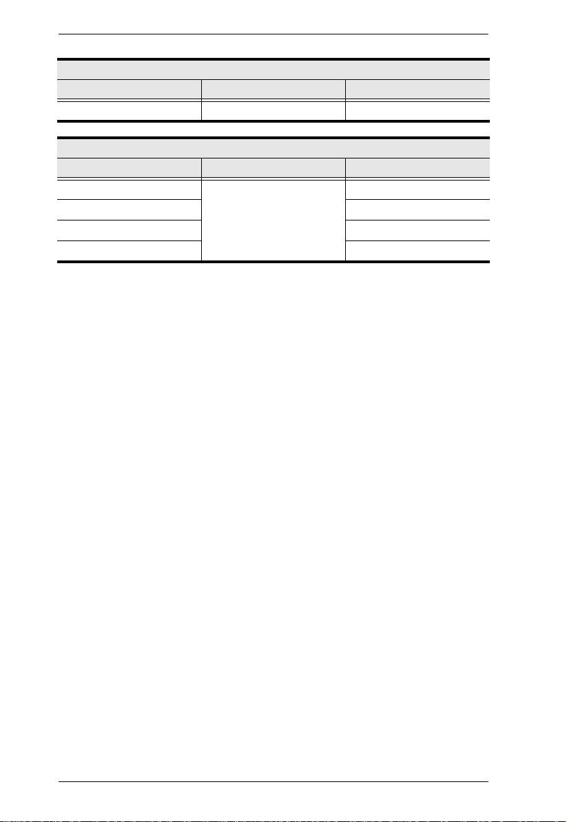
Rear Panel External Console Ports
Model
CL3800 Yes Yes Yes Yes Yes
CL3700 Yes No Yes No No
CL3100 Yes Yes No Yes No
Keyboard/
Mouse
Audio
(Speakers)
HDMI VGA DVI
2

Chapter 1. Introduction
Features
Exclusive LED illumination light – designed by ATEN to illuminate the
keyboard and touchpad to allow visibility in low-light conditions
Short-depth design allows you to work with your rack-mounting
equipment in narrow spaces
Integrated LCD KVM console with 18.5'' LED-backlit widescreen LCD
monitor in a dual rail housing with top and bottom clearance for smooth
operation in a 1U high system rack (CL3800 only)
Dual rail design allows LCD monitor and keyboard/touchpad modules to
operate independently (CL3800 only)
Integrated LCD KVM console with 18.5'' LED-backlit widescreen LCD
monitor in a single rail housing with top and bottom clearance for smooth
operation in a 1U high system rack (CL3700 and CL3100)
Supports three types of video input – HDMI, DVI, and VGA*; supports an
external console with USB / HDMI / VGA / DVI connectors* (CL3800
only)
Supports HDMI video input; supports an external console with USB /
HDMI connectors (CL3700 only)
Supports VGA video input; supports an external console with USB / VGA
connectors (CL3100 only)
LCD monitor supports Full HD resolution of 1920 x 1080 @ 60 Hz
(CL3800NW and CL3700NW only); LCD monitor supports resolution of
1366 x 768 @ 60 Hz (CL3800NX, CL3700NX, CL3100NX)
External console supports input video resolutions up to 1920 x 1200 @ 60
Hz
Audio support for connecting speakers (CL3800 and CL3100 only)
Console lock – enables the console drawer to remain securely locked away
in position when not in use
Additional hot-pluggable USB mouse port on front panel (also functions
as a USB peripheral port)
Console selection via hotkey
Standard 105-key keyboard
Optional 2-in-1U Mounting Kit (2K-0001/2K-0002) – fitting the CL3800/
CL3700/CL3100 and a rack KVM switch in 1U of space on a rack for
space-saving, easy and flexible operation
3

CL3800 / CL3700 / CL3100 User Manual
Optional rack mount kits available, including easy installation options
No software required
Firmware upgradable
Supports hot-plugging
Note: Only one video signal (HDMI, DVI-D, or VGA) can be displayed at
time.
4

Chapter 1. Introduction
Requirements
LCD Console
The CL3800 supports most ATEN HDMI, DVI, and VGA KVM switches;
the CL3700 supports most ATEN HDMI KVM switches; the CL3100
supports most ATEN VGA KVM switches.
For CL3800NW and CL3700NW models, the integrated LCD monitor's
maximum resolution is 1920 x 1080 @ 60 Hz; for CL3800NX,
CL3700NX, and CL3100NX models, the integrated LCD monitor's
maximum resolution is 1366 x 768 @ 60 Hz. Make sure that none of the
resolution settings of the connected computers exceed the LCD monitor's
maximum resolution.
External Console
An HDMI, DVI, or VGA monitor capable of displaying the highest
resolution provided by any computer in the installation (CL3800).
An HDMI monitor capable of displaying the highest resolution provided
by any computer in the installation (CL3700).
A VGA monitor capable of displaying the highest resolution provided by
any computer in the installation (CL3100).
USB keyboard and mouse
Cables
For optimum signal integrity and to simplify the layout, we strongly
recommend that you use high quality custom cable sets available in varying
lengths, described in the table below, which c an be purchased from yo ur dealer.
CL3800
Length (m) Typ e Part Number
1.80 USB, DVI 2L-7D02U
USB, HDMI 2L-7D02UH
USB, HDMI to DVI 2L-7D02DH
3.00 USB, DVI 2L-7D03U
5.00 USB, DVI 2L-7D05U
5
CL3800 / CL3700 / CL3100 User Manual
Length (m) Typ e Part Number
1.80 USB, HDMI 2L-7D02UH
Length (m) Typ e Part Number
1.20 USB, VGA 2L-5201U, 2L-5301U
1.80 2L-5202U, 2L-5302U
3.00 2L-5203U, 2L-5303U
5.00 2L-5205U,2L-5305U
CL3700
CL3100
6

Chapter 1. Introduction
Operating Systems
Supported operating systems include Windows, Mac, Linux, and Sun.
7
CL3800 / CL3700 / CL3100 User Manual
EXIT/ LIGHT
1
2
3
4
5
8
9
6
7
13
14
10
11
16
15
12
8
10
17
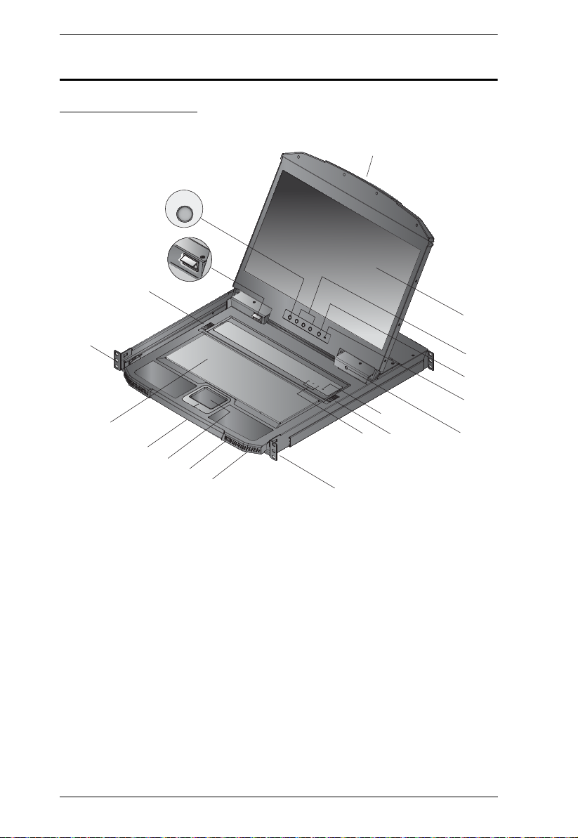
Components
CL3800 Front View
8

Chapter 1. Introduction
No. Component Description
1 Upper Handle Pull to slide the LCD module out; push to slide it in.
See Opening / Closing the Console, page 31, for details on
sliding the console in and out
2 LCD Module After sliding the LCD module out, flip up the cover to access
the LCD display.
3 LCD Controls The buttons to control the position and picture settings of the
LCD display are located here. See page 37, for details.
4 LCD On / Off
Button
Push this button to turn the LCD monitor on and off. The
button lights when the LCD monitor is off.
Note: The light indicates that only the monitor is off, not the
attached KVM switch.
5 Firmware
Upgrade Switch
During normal operation and while performing a firmware
upgrade, this switch should be in the NORMAL position. If a
firmware upgrade operation does not complete successfully,
see Upgrade Failed, page 48 for details on how to recover
the situation.
6 Firmware
Upgrade Port
The firmware upgrade cable that transfers the firmware
upgrade data from the administrator’s computer plugs into
this 3.5 mm audio jack.
7 Reset Switch Located to the right of the Lock LEDs. Press this recessed
switch in with a thin object to perform a system reset.
8 Keyboard Module
Releases
These catches (one on each side) release the keyboard
module so you can slide it away.
9 Lock LEDs The Num Lock, Caps Lock, Scroll Lock LEDs are located
here.
10 Rack Mounting
Brackets
Rack mounting brackets are located at each corner of the
unit. See Standard Rack Mounting, page 19, for details.
11 Power LED Lights (green) to indicate that the unit is receiving power.
12 USB Port The USB port is available to connect a USB peripheral
device (flash drive, CD-ROM drive, etc.) to the console, or a
USB mouse for users who prefer to use an external mouse.
13 Touchpad Standard mouse touchpad.
14 Bottom Handle Pull to slide the keyboard module out. See Opening / Closing
the Console, page 31, for details on sliding the console in
and out.
15 Keyboard Module Standard 105-key keyboard.
9

CL3800 / CL3700 / CL3100 User Manual
No. Component Description
16 LED Illumination
Light
17 Exit/Light
Pushbutton
Illuminates the keyboard and touchpad to allow visibility in
low-light conditions.
Press the Exit/Light pushbutton for two seconds to turn the
LED Illumination Light On or Off. (Default: On)
10
Chapter 1. Introduction
1
2
4
3
5
HDMI
HDMI
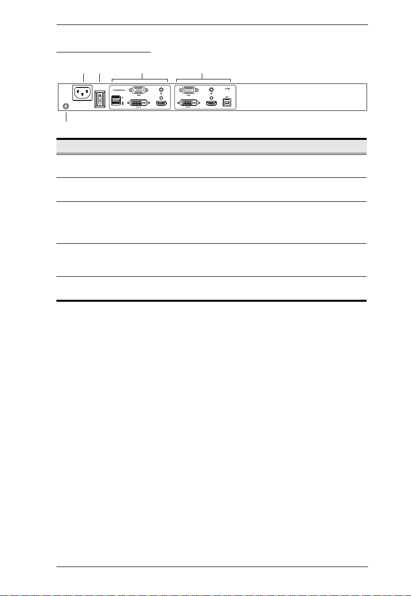
CL3800 Rear View
No. Component Description
1 Power Socket This is a standard 3 prong AC power socket. The power cord
2 Power Switch This is a standard rocker switch that powers the CL3800 on
3 External
Console Section
4KVM Port
Section
5 Grounding
Terminal
from an AC source plugs in here.
and off.
For flexibility and convenience, the CL3800 supports an
independent, external, KVM console. The external console's
USB keyboard and mouse, HDMI, DVI, or VGA monitor, and
speaker cable plug in here.
The custom USB HDMI KVM cable supplied with the package
for linking the CL3800 to a computer or switch plugs in here.
Additional DVI and VGA ports are provided.
The grounding wire (used to ground the unit) attaches here.
11
CL3800 / CL3700 / CL3100 User Manual
2
4
3
EXIT LIGHT
1
2
3
4
5
8
9
6
7
13
14
10
11
12
9
/
15
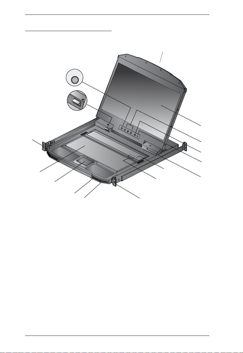
CL3700 / CL3100 Front View
12

Chapter 1. Introduction
No. Component Description
1 Upper Handle
With Release Bar
Pull to slide the LCD module out; push to slide it in.
See Opening / Closing the Console, page 31, for details on
sliding the console in and out
2 LCD Module After sliding the LCD module out, flip up the cover to access
the LCD display.
3 LCD Controls The buttons to control the position and picture settings of the
LCD display are located here. See page 37, for details.
4 LCD On / Off
Button
5 Firmware
Upgrade Switch
Push this button to turn the LCD monitor on and off. The
button lights when the LCD monitor is off.
Note: The light indicates that only the monitor is off, not the
attached KVM switch.
During normal operation and while performing a firmware
upgrade, this switch should be in the NORMAL position. If a
firmware upgrade operation does not complete successfully,
see Upgrade Failed, page 48 for details on how to recover
the situation.
6 Firmware
Upgrade Port
The firmware upgrade cable that transfers the firmware
upgrade data from the administrator’s computer plugs into
this 3.5 mm audio jack.
7 Reset Switch Located to the right of the Lock LEDs. Press this recessed
switch in with a thin object to perform a system reset.
8 Lock LEDs The Num Lock, Caps Lock, Scroll Lock LEDs are located
here.
9 Rack Mounting
Brackets
Rack mounting brackets are located at each corner of the
unit. See Standard Rack Mounting, page 19, for details.
10 Power LED Lights (green) to indicate that the unit is receiving power.
11 USB Port The USB port is available to connect a USB peripheral
device (flash drive, CD-ROM drive, etc.) to the console, or a
USB mouse for users who prefer to use an external mouse.
12 Touchpad Standard mouse touchpad.
13 Keyboard Module Standard 105-key keyboard.
14 LED Illumination
Light
15 Exit/Light
Pushbutton
Illuminates the keyboard and touchpad to allow visibility in
low-light conditions.
Press the Exit/Light pushbutton for two seconds to turn the
LED Illumination Light On or Off. (Default: On)
13
CL3800 / CL3700 / CL3100 User Manual
1
2
4
3
5
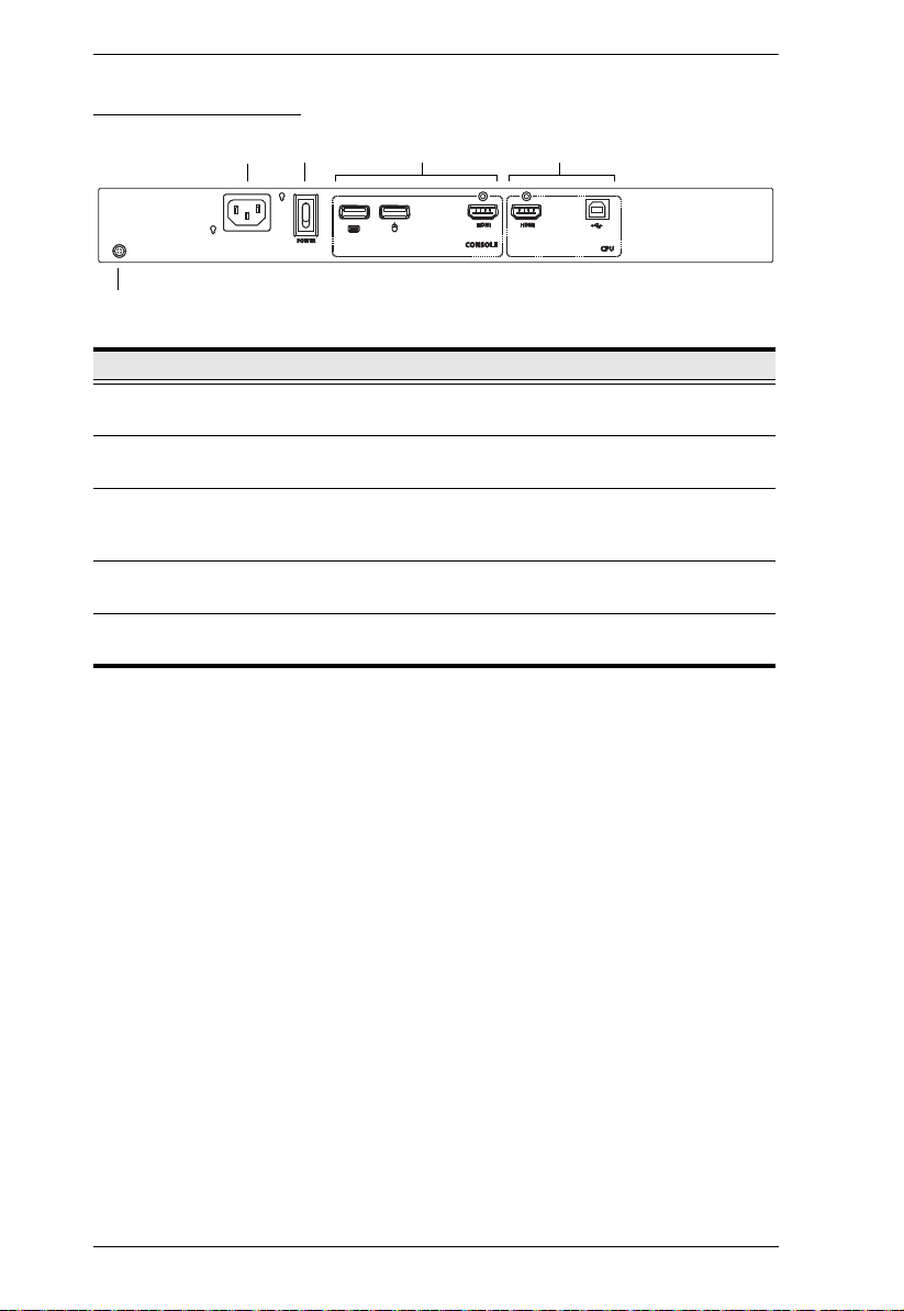
CL3700 Rear View
No. Component Description
1 Power Socket This is a standard 3 prong AC power socket. The power cord
2 Power Switch This is a standard rocker switch that powers the CL3700 on
3 External
Console Section
4 KVM Port
Section
5 Grounding
Terminal
from an AC source plugs in here.
and off.
For flexibility and convenience, the CL3700 supports an
independent, external, KVM console. The external console's
USB keyboard and mouse, and HDMI cable plug in here.
The custom USB HDMI KVM cable supplied with the package
for linking the CL3700 to a computer or switch plugs in here.
The grounding wire (used to ground the unit) attaches here.
14

CL3100 Rear View
Chapter 1. Introduction
1
2
3
4
5
No. Component Description
1 Power Socket This is a standard 3 prong AC power socket. The power cord
2 Power Switch This is a standard rocker switch that powers the CL3100 on
3 External
Console Section
4KVM Port
Section
5 Grounding
Terminal
from an AC source plugs in here.
and off.
For flexibility and convenience, the CL3100 supports an
independent, external, KVM console. The external console's
USB keyboard and mouse, VGA monitor, and speaker cable
plug in here.
The custom KVM cable supplied with the package for linking
the CL3100 to a computer or switch plugs in here.
The grounding wire (used to ground the unit) attaches here.
15

CL3800 / CL3700 / CL3100 User Manual
This Page Intentionally Left Blank
16

Chapter 2
1. Important safety information regarding the placement of this
device is provided on page 51. Please review it before
proceeding.
2. Make sure that power to all the devices you will be connecting
up has been turned off. You must unplug the power cords of any
computers that have the Keyboard Power On function.
3. (CL3800 only) Packing material has been inserted to protect the
CL3800 during shipping. Slide the LCD module out (see
Opening / Closing the Console, page 31), until the packing
material is visible. Remove the packing material before
installing the unit, as shown in the diagram below.
Hardware Setup
Before you Begin
17

CL3800 / CL3700 / CL3100 User Manual
Place on Flat Surface
4. The LCD KVM switch is designed for rack mounting. If the KVM switch
is not rack mounted be sure to place it on a completely flat and firm
surface before pulling the device in or out to prevent damage due to
uneven force on the module.
18

Chapter 2. Hardware Setup
Standard Rack Mounting
A standard rack mounting kit enables the CL3800 to be mounted in a rack with
a depth of 47–75 cm. A standard rack mounting kit enables the CL3700/
CL3100 to be mounted in a rack with a depth of 42-72 cm.
Left & Right L-shaped Brackets
Note: It takes two people to mount the console.
The standard rack mounting kit does not include screws or cage
nuts. If you need additional screws or cage nuts, contact your rack
dealer.
19

CL3800 / CL3700 / CL3100 User Manual
To rack mount the CL3800 / CL3700 / CL3100, do the following:
1. Attach the left and right L-shaped brackets to the back of the rack,
installing four screws in the brackets to secure them in place.
2. While one person inserts the unit into place by sliding its left and right side
bars into the left & right L-shaped brackets (on the rack), have a second
person screw the front brackets to the rack.
3. After the front brackets are secured, tighten all the screws.
Allow at least 5.1 cm on each side for proper ventilation, and at least 12.7
cm at the back for the power cord and cable clearance.
20

Chapter 2. Hardware Setup
Front-L Brackets Mounting (CL3800 only)
To have a comfortable and safe posture, install the Front-L Brackets which
provide an extension at the front of the rack to help the unit slide further out
and thus allowing you to tilt the LCD screen more. Instructions to use this
option are shown below:
1. Attach the left and right Front-L brackets to the front of the rack, placing
screws in the tabs to secure them in place.
Note: Rack screws are not provided to mount the unit. We recommend that
you use M5 x P0.8 screws.
2. Attach the left and right L-shaped brackets to the back of the rack,
installing four screws in the brackets to secure them in place.
21

CL3800 / CL3700 / CL3100 User Manual
The CL5800 LCD KVM shown
here is used as a schematic representation
of this step.
3. While one person inserts the unit into place by sliding its left and right side
bars into the left and right L-shaped brackets (on the rack), have a second
person screw the front brackets to the front-L bracket.
4. After the front brackets are secured, tighten all the screws.
Allow at least 5.1 cm on each side for proper ventilation, and at least 12.7
cm at the back for the power cord and cable clearance.
22

Chapter 2. Hardware Setup
Optional Rack Mount Kits
For convenience and flexibility, optional rack mount kits are available and are
listed in the table below:
Mounting Kit Description
Standard Long Rack Mount
Kit
Easy Installation Rack
Mount Kit
Note: For more information, visit the product webpage and refer to the
Compatible Accessories.
For detailed installation steps, visit the product webpage and refer
to the Optional Rack Mount Kits Installation Guide.
This kit is the long-railed version of your standard
mounting kit that lets you fit your device to racks with
greater depth.
This kit is designed to be easy to install and can be
installed by one person
23

CL3800 / CL3700 / CL3100 User Manual
Connecting Up - CL3800
Refer to the example installation diagram in the next page as you perform the
following steps:
1. Plug the USB, audio and one of HDMI, DVI-D, or VGA connectors of a
KVM cable (either supplied with the unit, or purchased separately, see
Cables, page 5) into the KVM ports located in the CPU section on the rear
of the CL3800.
Note: The CL3800 supports speakers only. It does not support a
microphone. Connect the KVM cable’s speaker jack (green) to the
CL3800’s audio port.
2. Plug the keyboard, monitor, mouse and audio connectors of the KVM
cable into their respective ports in the Console Section of a KVM switch.
3. If you are installing an external console, plug your keyboard, monitor,
mouse and speakers into their respective ports in the Console Section of
the CL3800.
Note: The CL3800 supports an HDMI, DVI-D, or VGA external console
monitor, but only one video signal (HDMI, VGA, or DVI-D) can be
displayed at a time. The DVI monitor will display a DVI-D signal
only.
4. Plug the CL3800’s power cord into the CL3800’s power socket and into a
power source.
5. Turn on the power to LCD Console.
6. Power on your PC.
24

Installation Diagram
5
3
4
1
CL3800 (Rear)
HDMI, DVI-D,
or VGA
2
KVM Switch (Rear)
Chapter 2. Hardware Setup
25

CL3800 / CL3700 / CL3100 User Manual
Connecting Up - CL3700
Refer to the example installation diagram below as you perform the following
steps:
1. Plug the HDMI and USB Type B connectors of a KVM cable into the
KVM ports located in the CPU section on the rear of the CL3700.
2. Plug the HDMI and USB Type B connectors of the KVM cable into their
respective ports in the Console Section of a KVM switch.
3. If you are installing an external console, plug your keyboard, mouse, and
monitor into their respective ports on the Console Section of the CL3700.
4. Plug one end of the CL3700’s power cord into the CL3700's power socket,
and plug the other end into a power source.
5. Turn on the power to the LCD Console.
6. Power on your PC.
26

Installation Diagram
5
3
4
1
CL3700 (Rear)
HDMI
2
KVM Switch (Rear)
Chapter 2. Hardware Setup
27

CL3800 / CL3700 / CL3100 User Manual
Connecting Up - CL3100
Refer to the example installation diagram below as you perform the following
steps:
1. Plug one end of the KVM cable into the KVM ports located in the CPU
section on the rear of the CL3100.
Note: The CL3100 supports speakers only. It does not support a
microphone. Connect the KVM cable’s speaker jack (green) to the
CL3100’s audio port.
2. Plug the other end of the KVM cable into the Console Section of a KVM
switch.
3. If you are installing an external console, plug your keyboard, mouse,
monitor, and speakers (microphone not supported) into their respective
ports on the Console Section of the CL3100.
4. Plug one end of the CL3100’s power cord into the CL3100’s power socket,
and plug the other end into a power source.
5. Turn on the power to LCD Console.
6. Power on your PC.
28

Installation Diagram
Chapter 2. Hardware Setup
VGA
3
4
KVM Switch (Rear)
CL3100 (Rear)
5
1
2
29

CL3800 / CL3700 / CL3100 User Manual
This Page Intentionally Left Blank
30

Chapter 3
Upper Release Bar
Operation
Opening / Closing the Console
The CL3800’s console consists of two modules: an 18.5” LCD display module
located under the top cover; and a keyboard / touch pad module below the LCD
module. The modules can either slide together, or independently. This allows
you to have the LCD display available for viewing while the keyboard / touch
pad module is conveniently out of the way when not in use.
The CL3700 and CL3100 are single rail consoles and so the LCD display
module and keyboard/touch pad module can only slide in/out together.
CL3800
1. Use the Upper Release Bar handle to pull the Panel module straight out.
31

CL3800 / CL3700 / CL3100 User Manual
2. Pulling, slide the Panel module out until it clicks in place.
3. Raise the top panel all the way back to expose the LCD screen.
32

Chapter 3. Operation
Lower Release Bar
4. Use the Lower Release Bar handle to pull the keyboard module straight
out unit it clicks in place.
5. To independently retract the keyboard into the rack, slide both Keyboard
Module Releases and push the keyboard module all the way in.
33

CL3800 / CL3700 / CL3100 User Manual
6. Slide the keyboard in until it's completely inserted into the rack.
7. To close the LCD screen, lower the panel module until it lies flat and slide
it back in.
34

Chapter 3. Operation
1
CL3700 / CL3100
Refer to the diagrams below to open or close the console as you do the
following:
1. Pull on the Release Bar on the upper handle. Slide the console module out
until it clicks in place, and then raise the LCD Module lid.
2. To close the console, lower the LCD Module until it lies flat, and slide the
full console in.
2
35

CL3800 / CL3700 / CL3100 User Manual
The maximum load bearing capacity of the keyboard module is 30 kg.
Failure to heed the information below can result in damage to the
keyboard module.
Operating Precautions
Right!
Rest your hands and arms lightly on the
keyboard module as you work.
Wrong!
DO NOT lean your body weight on the
keyboard module.
DO NOT place heavy objects on the
keyboard module.
36

Chapter 3. Operation
LCD OSD Configuration
LCD Buttons
The LCD OSD allows you to set up and configure the LCD display. Four
buttons are used to perform the configuration, as described in the table, below:
Button Function
MENU
EXIT
When you have not entered the LCD OSD Menu function,
pressing this button invokes the Menu function, and brings up
the Main Menu.
When you have entered the LCD OSD Menu function, and
have reached a setting choice with the navigation buttons,
pressing this button brings up its adjustment screen.
When navigating through the menus, this button moves you Right
or Up. When making an adjustment, it increases the value.
When navigating through the menus, this button moves you Left
or Down. When making an adjustment, it decreases the value.
When you have not entered the LCD OSD Menu function,
pressing this button performs an auto adjustment. An auto
adjustment automatically configures all the settings for the
LCD panel to what the OSD considers their optimum values to
be.
When you have entered the LCD OSD Menu function, pressing
this button exits the current menu and returns you to the
previous menu. Use it to leave an adjustment menu when you
are satisfied with the adjustment you made.
When you are at the Main Menu, pressing this button exits the
LCD OSD.
37

CL3800 / CL3700 / CL3100 User Manual
Adjustment Settings
An explanation of the LED OSD adjustment settings is given in the table
below:
Setting Explanation
Brightness Adjusts the background black level of the screen image.
Contrast Adjusts the foreground white level of the screen image.
Phase If pixel jitter or horizontal line noise is visible on the display,
Clock If vertical banding is visible on the display, your LED may
H-Position Positions the display area on the LED panel horizontally
V-Position Positions the display area on the LED panel vertically
Color Temperature Adjusts the color quality of the display. You can adjust the
Language Selects the language that the OSD displays its menus in.
OSD Duration Lets you set the amount of time the OSD displays on the
Input Source Lets you select an Analog (VGA) or Digital (HDMI, DVI)
Reset Resets the adjustments on all menus and submenus to
your LED may have the wrong phase setting. Adjust the
phase setting to eliminate these problems.
have the wrong clock setting. Adjust the clock setting to
eliminate vertical banding.
(moves the display area left or right).
(moves the display area up or down).
warmth value, color balance, etc. The Adjust Color
selection has a further submenu that lets you fine tune the
RGB values.
screen. If there is no input for the amount of time you
choose, the OSD display turns off.
input source for connecting an external console to the
CL3800. This option is not available for the CL3700 or
CL3100 as they only have one input source option.
See External Console Section, page 11.
their factory default settings.
Note: The Language setting does not return to the factory
default, but remains at the one that you have set it to.
38

Chapter 3. Operation
Hot Plugging
The CL3800 / CL3700 / CL3100 supports hot plugging – components can be
removed and added to the console by unplugging their cables from the ports
without the need to shut down the CL3800 / CL3700 / CL3100.
Powering Off and Restarting
If it becomes necessary to Power Off the CL3800 / CL3700 / CL3100 (to
upgrade the firmware, for example), simply turn off the power to the unit using
the rear panel power switch. To restart the CL3800 / CL3700 / CL3100, turn
the rear panel power switch back on.
Port ID Numbering & Port Selection
If you connect a KVM switch to the CL3800 / CL3700 / CL3100, Port ID
numbering and Port Selection follow the method used by the connected KVM
switch. Consult your KVM switch's user manual for details.
39

CL3800 / CL3700 / CL3100 User Manual
Hotkeys
Console selection is accomplished with the following hotkey combinations:
Combination Action Beeps LEDs
[Ctrl] [Alt] [Shift] [P] [C]
[Enter]
[Ctrl] [Alt] [Shift] [M] [A] [C]
[Enter]
[Ctrl] [Alt] [Shift] [S] [U] [N]
[Enter]
[Ctrl] [Alt] [Shift]
[u] [p] [g] [r] [a] [d] [e]
[Enter]
[Ctrl] [Alt] [Shift] [L] [Enter] Enable Local (LCD) console; Disable
[Ctrl] [Alt] [Shift] [R] [Enter] Enable 2nd console, or external
[Ctrl] [Alt] [Shift] [L] [R]
[Enter] or
[Ctrl] [Alt] [Shift] [R] [L]
[Enter]
[Ctrl] [Alt] [Shift] [U] [M]
[Enter]
[Ctrl] [Alt] [Shift] [U] [P]
[Enter]
[Ctrl] [Alt] [Shift] [F4]
[Enter]
[Ctrl] [Alt] [Shift] [F11] [F]
[Enter]
[Ctrl] [Alt] [Shift] [F11] [L]
[Enter]
To select normal mode (pc, etc.). 2 None
To select Mac 2 None
To select SUN 2 None
Activates the Firmware Upgrade
Mode.
Note: this Hotkey sequence only
works when the firmware upgrade
switch (see page 44) is in the
Normal position.
2nd console or external console
video.
console video; Disable Local (LCD)
console.
Enable both consoles (default). 2 None
Configures the front USB Port to
mouse mode (Mouse functionality is
immediate upon switching to USB
mouse mode). (USB mouse mode
[U] [M] is the default)
Configures the front USB Port to
peripheral mode.
Print the switch’s current settings via
a text editor or word processor.
Set the KVM port to USB full speed. 2 None
Set the KVM port to USB low speed. 1 None
None 3
Flashing
when
upgrade
is in
process
2 None
2 None
2 None
2 None
None None
Note: 1. Press the keys in sequence – one key at a time. First [Ctrl], then [Alt],
then [Shift], etc.
40

Chapter 3. Operation
2. Console selections are not saved. If the CL3800 / CL3700 / CL3100
is powered off, it reverts to the default setting of both consoles
enabled when it is powered on again.
3. Either side of the keyboard can be used to invoke [Shift] [Ctrl] [Alt]
hotkeys. However, when activating hotkey combinations [C trl] [Alt]
[Shift], make sure you are using the keys on the same side of the
keyboard.
4. If the KVM switch connected to the CL3800 / CL3700 / CL3100 uses
the [Ctrl] [Alt] [Shift] combination to invoke its hotkey mode, you
won’t be able to access any of its hotkey operations because the
CL3800 / CL3700 / CL3100 will capture the combination for console
selection first.
41

CL3800 / CL3700 / CL3100 User Manual
This Page Intentionally Left Blank
42

Chapter 4
Firmware Upgrade
The Firmware Upgrade Utility
As new firmware revisions become available for the CL3800 / CL3700 /
CL3100, firmware upgrade packages are posted on the ATEN web site. The
Windows-based Firmware Upgrade Utility (FWUpgrade.exe) provides a
smooth, automated process for upgrading the CL3800 / CL3700 / CL3100’s
firmware. Check the web site regularly to find the latest firmware packages and
information relating to them.
Before You Begin
To prepare for the firmware upgrade, do the following:
1. From a computer that is not part of your CL3800 / CL3700 / CL3100
installation go to ATEN’s Internet support site and choose the model name
that relates to your device to get a list of available Firmware Upgrade
Packages.
2. Choose the Firmware Upgrade Package you want to install (usually the
most recent), and download it to your computer.
3. Use the Firmware Upgrade Cable (provided with this unit), to connect a
COM port on your computer to the Firmware Upgrade Port of the
CL3800 / CL3700 / CL3100.
43

CL3800 / CL3700 / CL3100 User Manual
Firmware Upgrade Mode
The CL3800 / CL3700 / CL3100’s firmware upgrade mode can be accessed
one of two ways: by entering a hotkey sequence (see Hotkeys, page 40), or by
sliding the Firmware Upgrade Switch of the CL3800 / CL3700 / CL3100 to
RECOVER (see Upgrade Failed, page 48).
Note: In order to activate the Firmware Upgrade Mode using a hotkey
sequence, the firmware upgrade switch (see page 9) must be set to the
Normal position.
1. Turn off the power to the CL3800 / CL3700 / CL3100 using the power
switch located on the back side of the console.
2. Slide the firmware switch to RECOVER (see page 9).
3. Turn on the power to the CL3800 / CL3700 / CL3100 using the power
switch located on the back side of the console.
When the CL3800 / CL3700 / CL3100 is in Firmware Upgrade Mode, the Num
Lock, Caps Lock and Scroll Lock LEDs will continually flash on and off.
To exit the Firmware Upgrade Mode, see Exiting Firmware Upgrade Mode,
page 49.
44

Chapter 4. Firmware Upgrade
Performing the Upgrade
Starting the Upgrade:
1. With the CL3800 / CL3700 / CL3100 in Firmware Upgrade Mode, run the
downloaded Firmware Upgrade Package file from your computer - either
by double clicking the file icon, or by opening a command line and keying
in the full path and filename.
The Firmware Upgrade Utility Welco me screen appears:
2. Read and Agree to the License Agreement (enable the I Agree radio
button).
(Continues on next page.)
45

CL3800 / CL3700 / CL3100 User Manual
(Continued from previous page.)
3. Click Next. The Firmware Upgrade Utility main screen appears:
The Utility inspects your installation. All the devices capable of being
upgraded by the package are listed in the Device List panel.
4. Click Next to perform the upgrade.
If you enabled Check Firmware Version, the Utility compares the
device's firmware level with that of the upgrade files. If it finds that the
device's version is higher than the upgrade version, it brings up a
dialog box informing you of the situation and gives you the option to
continue the upgrade:
If you didn't enable Check Firmware Version, the Utility installs the
upgrade files without checking whether they are a higher level, or not.
As the Upgrade proceeds status messages appear in the Status
Messages panel, and the progress toward completion is shown on the
Progress bar.
46

Chapter 4. Firmware Upgrade
Upgrade Succeeded
After the upgrade has completed, a screen appears to inform you that the
procedure was successful:
Click Finish to close the Firmware Upgrade Utility.
47

CL3800 / CL3700 / CL3100 User Manual
Upgrade Failed
If the firmware upgrade fails (Upgrade Succeeded screen does not appear), you
can recover the situation.
Possible reasons for firmware upgrade failure are:
When a firmware upgrade was manually aborted.
When the unit’s firmware becomes corrupted for some reason and you are
unable to operate it.
When a firmware upgrade procedure is interrupted.
When a firmware upgrade procedure fails.
To recover a failed firmware upgrade, do the following:
1. Power off the unit.
2. Connect the Firmware Upgrade Cable to its Firmware Upgrade Port.
3. Slide the Firmware Upgrade Switch to the Recover position.
4. Power the unit back on and repeat the upgrade procedure (see Starting the
Upgrade: on page 45).
5. After the unit has been successfully upgraded, power it off, and slide the
Firmware Upgrade Switch back to the Normal position.
6. Power the unit back on again.
48

Chapter 4. Firmware Upgrade
Exiting Firmware Upgrade Mode
To exit the Firmware Upgrade Mode, do the following:
1. Slide the firmware upgrade switch (see page 9) to the Normal position.
2. Power off and restart the CL3800 / CL3700 / CL3100 according to the
instructions given in the Powering Off and Restarting section (see
page 39).
49

CL3800 / CL3700 / CL3100 User Manual
This Page Intentionally Left Blank
50

Appendix
Safety Instructions
General
This product is for indoor use only.
Read all of these instructions. Save them for future reference.
Follow all warnings and instructions marked on the device.
Do not place the device on any unstable surface (cart, stand, table, etc.). If
the device falls, serious damage will result.
Do not use the device near water.
Do not place the device near, or over, radiators or heat registers.
The device cabinet is provided with slots and openings to allow for
adequate ventilation. To ensure reliable operation, and to protect against
overheating, these openings must never be blocked or covered.
The device should never be placed on a soft surface (bed, sofa, rug, etc.) as
this will block its ventilation openings. Likewise, the device should not be
placed in a built in enclosure unless adequate ventilation has been provided.
Never spill liquid of any kind on the device.
Unplug the device from the wall outlet before cleaning. Do not use liquid
or aerosol cleaners. Use a damp cloth for cleaning.
The device should be operated from the type of power source indicated on
the marking label. If you are not sure of the type of power available,
consult your dealer or local power company.
The device is designed for IT power distribution systems with 230V
phase-to-phase voltage.
To prevent damage to your installation it is important that all devices are
properly grounded.
The device is equipped with a 3-wire grounding type plug. This is a safety
feature. If you are unable to insert the plug into the outlet, contact your
electrician to replace your obsolete outlet. Do not attempt to defeat the
purpose of the grounding-type plug. Always follow your local/national
wiring codes.
Do not allow anything to rest on the power cord or cables. Route the
power cord and cables so that they cannot be stepped on or tripped over.
51

CL3800 / CL3700 / CL3100 User Manual
If an extension cord is used with this device make sure that the total of the
ampere ratings of all products used on this cord does not exceed the
extension cord ampere rating. Make sure that the total of all products
plugged into the wall outlet does not exceed 15 amperes.
To help protect your system from sudden, transient increases and
decreases in electrical power, use a surge suppressor, line conditioner, or
uninterruptible power supply (UPS).
Position system cables and power cables carefully; Be sure that nothing
rests on any cables.
Never push objects of any kind into or through cabinet slots. They may
touch dangerous voltage points or short out parts resulting in a risk of fire
or electrical shock.
Do not attempt to service the device yourself. Refer all servicing to
qualified service personnel.
If the following conditions occur, unplug the device from the wall outlet
and bring it to qualified service personnel for repair.
The power cord or plug has become damaged or frayed.
Liquid has been spilled into the device.
The device has been exposed to rain or water.
The device has been dropped, or the cabinet has been damaged.
The device exhibits a distinct change in performance, indicating a need
for service.
The device does not operate normally when the operating instructions
are followed.
Only adjust those controls that are covered in the operating instructions.
Improper adjustment of other controls may result in damage that will
require extensive work by a qualified technician to repair.
Do not connect the Audio Jack connector marked “UPGRADE” to a
public telecommunication network.
Avoid circuit overloads. Before connecting equipment to a circuit, know
the power supply’s limit and never exceed it. Always review the electrical
specifications of a circuit to ensure that you are not creating a dangerous
condition or that one doesn’t already exist. Circuit overloads can cause a
fire and destroy equipment.
Suitable for installation in Information Technology Rooms in accordance
with Article 645 of the National Electrical Code NFPA 75.
52

Appendix
Rack Mounting
Before working on the rack, make sure that the stabilizers are secured to
the rack, extended to the floor, and that the full weight of the rack rests on
the floor. Install front and side stabilizers on a single rack or front
stabilizers for joined multiple racks before working on the rack.
Always load the rack from the bottom up, and load the heaviest item in the
rack first.
Make sure that the rack is level and stable before extending a device from
the rack.
Use caution when pressing the device rail release latches and sliding a
device into or out of a rack; the slide rails can pinch your fingers.
After a device is inserted into the rack, carefully extend the rail into a
locking position, and then slide the device into the rack.
Do not overload the AC supply branch circuit that provides power to the
rack. The total rack load should not exceed 80 percent of the branch circuit
rating.
Make sure that all equipment used on the rack – including power strips and
other electrical connectors – is properly grounded.
Ensure that proper airflow is provided to devices in the rack.
Ensure that the operating ambient temperature of the rack environment
does not exceed the maximum ambient temperature specified for the
equipment by the manufacturer.
Do not step on or stand on any device when servicing other devices in a
rack.
Caution: Slide/rail (LCD KVM) mounted
equipment is not to be used as a shelf or a work
space.
53

CL3800 / CL3700 / CL3100 User Manual
Consignes de sécurité
Général
Ce produit est destiné exclusivement à une utilisation à l’intérieur.
Veuillez lire la totalité de ces instructions. Conservez-les afin de pouvoir
vous y référer ultérieurement.
Respectez l’ensemble des avertissements et instructions inscrits sur
l’appareil.
Ne placez jamais l’unité sur une surface instable (chariot, pied, table, etc.).
Si l’unité venait à tomber, elle serait gravement endommagée.
N’utilisez pas l’unité à proximité de l’eau.
Ne placez pas l’unité à proximité de ou sur des radiateurs ou bouches de
chaleur.
Le boîtier de l’unité est doté de fentes et d’ouvertures destinées à assurer
une ventilation adéquate. Pour garantir un fonctionnement fiable et
protéger l’unité contre les surchauffes, ces ouvertures ne doivent jamais
être bloquées ou couvertes.
L’unité ne doit jamais être placée sur une surface molle (lit, canapé, tapis,
etc.) car ses ouvertures de ventilation se trouveraient bloquées. De même,
l’unité ne doit pas être placée dans un meuble fermé à moins qu'une
ventilation adaptée ne soit assurée.
Ne renversez jamais de liquides de quelque sorte que ce soit sur l’unité.
Débranchez l’unité de la prise murale avant de la nettoyer. N’utilisez pas
de produits de nettoyage liquide ou sous forme d’aérosol. Utilisez un
chiffon humide pour le nettoyage de l’unité.
Evitez toute surcharge du circuit. Avant de connecter l’equipement a un
circuit, verifiez la limite de l’alimentation et ne la depassez pas. Controlez
toujours les caracteristiques electriques d'un circuit pour vous assurer de
ne pas creer de situation dangereuse ou qu’il n’y en a pas deja. Les
surcharges du circuit peuvent provoquer un incendie et detruire
l’equipement.
L’appareil doit être alimenté par le type de source indiqué sur l’étiquette.
Si vous n’êtes pas sûr du type d’alimentation disponible, consultez votre
revendeur ou le fournisseur local d’électricité.
Afin de ne pas endommager votre installation, vérifiez que tous les
périphériques sont correctement mis à la terre.
54

Appendix
L’unité est équipée d’une fiche de terre à trois fils. Il s’agit d’une fonction
de sécurité. Si vous ne parvenez pas à insérer la fiche dans la prise murale,
contactez votre électricité afin qu’il remplace cette dernière qui doit être
obsolète. N’essayez pas d’aller à l’encontre de l’objectif de la fiche de
terre. Respectez toujours les codes de câblage en vigueur dans votre
région/pays.
L’équipement doit être installé à proximité de la prise murale et le
dispositif de déconnexion (prise de courant femelle) doit être facile
d’accès.
La prise murale doit être installée à proximité de l’équipement et doit être
facile d’accès.
Veillez à ce que rien ne repose sur le cordon d’alimentation ou les câbles.
Acheminez le cordon d’alimentation et les câbles de sorte que personne ne
puisse marcher ou trébucher dessus.
En cas d’utilisation d’une rallonge avec cette unité, assurez-vous que le
total des ampérages de tous les produits utilisés sur cette rallonge ne
dépasse pas l’ampérage nominal de cette dernière. Assurez-vous que le
total des ampérages de tous les produits branchés sur la prise murale ne
dépasse pas 15 ampères.
Pour contribuer à protéger votre système contre les augmentations et
diminutions soudaines et transitoires de puissance électrique, utilisez un
parasurtenseur, un filtre de ligne ou un système d’alimentation sans
coupure (UPS).
Placez les câbles du système et les câbles d’alimentation avec précaution ;
veillez à ce que rien ne repose sur aucun des câbles.
Lors du branchement ou du débranchement à des blocs d’alimentation
permettant la connexion à chaud, veuillez respecter les lignes directrices
suivantes:
Installez le bloc d’alimentation avant de brancher le câble d’alimentation à
celui-ci.
Débranchez le câble d’alimentation avant de retirer le bloc d'alimentation.
Si le système présente plusieurs sources d’alimentation, déconnectez le
système de l'alimentation en débranchant tous les câbles d'alimentation des
blocs d'alimentation.
N’insérez jamais d’objets de quelque sorte que ce soit dans ou à travers les
fentes du boîtier. Ils pourraient entrer en contact avec des points de tension
dangereuse ou court-circuiter des pièces, entraînant ainsi un risque
d’incendie ou de choc électrique.
55

CL3800 / CL3700 / CL3100 User Manual
N’essayez pas de réparer l’unité vous-même. Confiez toute opération de
réparation à du personnel qualifié.
Si les conditions suivantes se produisent, débranchez l’unité de la prise
murale et amenez-la à un technicien qualifié pour la faire réparer:
Le cordon d’alimentation ou la fiche ont été endommagés ou éraillés.
Du liquide a été renversé dans l’unité.
L’unité a été exposée à la pluie ou à l’eau.
L’unité est tombée ou le boîtier a été endommagé.
Les performances de l’unité sont visiblement altérées, ce qui indique la
nécessité d’une réparation.
L’unité ne fonctionne pas normalement bien que les instructions
d’utilisation soient respectées.
N’utilisez que les commandes qui sont abordées dans le mode d’emploi.
Le réglage incorrect d’autres commandes peut être à l’origine de
dommages qui nécessiteront beaucoup de travail pour qu’un technicien
qualifié puisse réparer l’unité.
Ne connectez pas le connecteur RJ-11 portant la marque « Sensor »
(Capteur) à un réseau de télécommunication public.
Peut être installé dans des salles de matériel de traitement de l’information
conformément à l’article 645 du National Electrical Code et à la NFPA 75.
56

Appendix
Montage sur bâti
Avant de travailler sur le bâti, assurez-vous que les stabilisateurs sont bien
fixées sur le bâti, qu’ils sont étendus au sol et que tout le poids du bâti
repose sur le sol. Installez les stabilisateurs avant et latéraux sur un même
bâti ou bien les stabilisateurs avant si plusieurs bâtis sont réunis, avant de
travailler sur le bâti.
Chargez toujours le bâti de bas en haut et chargez l’élément le plus lourd
en premier.
Assurez-vous que le bâti est à niveau et qu’il est stable avant de sortir une
unité du bâti.
Agissez avec précaution lorsque vous appuyez sur les loquets de libération
du rail d’unité et lorsque vous faites coulisser une unité dans et hors d’un
bâti ; vous pourriez vous pincer les doigts dans les rails.
Une fois qu’une unité a été insérée dans le bâti, étendez avec précaution le
rail dans une position de verrouillage puis faites glisser l’unité dans le bâti.
Ne surchargez pas le circuit de l’alimentation CA qui alimente le bâti. La
charge totale du bâti ne doit pas dépasser 80 % de la capacité du circuit.
Assurez-vous que tous les équipements utilisés sur le bâti, y-compris les
multiprises et autres connecteurs électriques, sont correctement mis à la
terre.
Assurez-vous que les unités présentes dans le bâti bénéficie d’une
circulation d’air suffisante.
Assurez-vous que la température ambiante de fonctionnement de
l’environnement du bâti ne dépasse pas la température ambiante maximale
spécifiée pour l’équipement par le fabricant.
Ne marchez sur aucun appareil lors de la maintenance d’autres appareils
d’un bâti.
Attention: Glisser / rail (LCD KVM) monté
l'équipement ne doit pas être utilisé comme une
étagère ou un espace de travail.
57

CL3800 / CL3700 / CL3100 User Manual
Technical Support
International
For online technical support – including troubleshooting, documentation,
and software updates: http://support.aten.com
For telephone support, see Telephone Support, page iii.
North America
Email Support support@aten-usa.com
Online
Technical
Support
Telephone Support 1-888-999-ATEN ext 4988
When you contact us, please have the following information ready beforehand:
Product model number, serial number, and date of purchase.
Your computer configuration, including operating system, revision level,
expansion cards, and software.
Any error messages displayed at the time the error occurred.
The sequence of operations that led up to the error.
Any other information you feel may be of help.
Troubleshooting
Documentation
Software Updates
http://www.aten-usa.com/support
1-949-428-1111
58

Specifications
CL3800NW / CL3800NX
Function CL3800NW CL3800NX
Computer Connections
Direct 1
Console Selection Hotkey
Connectors
1 x HDMI Female
External Console Ports
KVM Ports
External Mouse / Peripheral
Firmware Upgrade 1 x 3.5 mm Audio Jack Female (Black)
Power 1 x IEC 60320/C14
Switches
Reset 1 x Semi-recessed Pushbutton
Firmware Upgrade 1 x Slide
Power 1 x Rocker
LCD Power 1 x Pushbutton
LCD Adjustment 4 x Pushbutton
LEDs
Power
Lock
Video
Input Video Resolution
up to 1920 x 1200 @ 60 Hz;
1920 x 1080 @ 60Hz,
1 x DVI-D Female (White)
1 x HDB-15 Female (Blue)
2 x USB Type A Female
1 x 3.5 mm Audio Jack Female (Green)
1 x HDMI Female
1 x DVI-D Female (White)
1 x HDB-15 Male (Blue)
1 x USB Type B Female
1 x 3.5 mm Audio Jack Female (Green)
1 x USB Type A Female (Front)
1 x KVM Console (Dark Green)
1 x LCD (Orange)
1 x Num Lock (Green)
1 x Caps Lock (Green)
1 x Scroll Lock (Green)
up to 1920 x 1200 @ 60 Hz;
DDC2B
1366 x 768 @ 60Hz, DDC2B
Appendix
59

CL3800 / CL3700 / CL3100 User Manual
Function CL3800NW CL3800NX
Panel Spec
LCD Module 18.5" TFT-LCD
Resolution 1920 x 1080 @ 60 Hz 1366 x 768 @ 60 Hz
Pixel Pitch 0.213 mm x 0.213 mm 0.3 mm x 0.3 mm
Response Time 20 ms 5 ms
Viewing Angle 178° (H), 178° (V) 170° (H), 160° (V)
Contrast Ratio 1000:1 1000:1
Support Color 16.77M colors 16.77M colors
Luminance 350 cd/m² 250 cd/m²
Emulation
Keyboard / Mouse USB
Maximum Input Power
Rating
Power Consumption
Environmental
Operating Temperature
Storage Temperature
Humidity 0–80% RH Non-condensing
Physical Properties
Housing Metal + Plastic
Weight 9.61 kg (21.17 lb) 9.79 kg (21.56 lb)
Dimensions (L x W x H)
Body Dimensions
(L x W x H)
AC110V: 26.6W:140BTU
AC220V: 26.8W:141BTU
100–240V AC; 50–60Hz; 1A
AC110: 18.3W:101BTU
AC220: 17.8W:98BTU
o
0–40
C
o
C
-20–60
48.06 x 51.42 x 4.28 cm
(18.92 x 20.24 x 1.69 in.)
44.92 x 46.74 x 4.28 cm
(17.69 x 18.40 x 1.69 in.)
Note: 1. For some rack mount products, please note that the standard physical
dimensions of WxDxH are expressed using a LxWxH format.
2. Body Dimensions exclude I/O ports, handles, and mounting brackets.
60

Appendix
CL3700NW / CL3700NX
Function CL3700NW CL3700NX
Computer Connections
Direct 1
Console Selection Hotkey
Connectors
External Console Ports
KVM Ports
External Mouse / Peripheral
Firmware Upgrade 1 x 3.5 mm Audio Jack Female (Black)
Power 1 x IEC 60320/C14
Switches
Reset 1 x Semi-recessed Pushbutton
Firmware Upgrade 1 x Slide
Power 1 x Rocker
LCD Power 1 x Pushbutton
LCD Adjustment 4 x Pushbutton
LEDs
Power
Lock
Emulation
Keyboard / Mouse USB
Video
Input Video Resolution
Panel Spec
LCD Module 18.5" TFT-LCD
Resolution 1920 x 1080 @ 60 Hz 1366 x 768 @ 60 Hz
Pixel Pitch 0.213 mm x 0.213 mm 0.3 mm x 0.3 mm
up to 1920 x 1200 @ 60 Hz;
1920 x 1080 @ 60Hz,
DDC2B
1 x HDMI Female
2 x USB Type A Female
1 x HDMI Female
1 x USB Type B Female
1 x USB Type A Female (Front)
1 x KVM Console (Dark Green)
1 x LCD (Orange)
1 x Num Lock (Green)
1 x Caps Lock (Green)
1 x Scroll Lock (Green)
up to 1920 x 1200 @ 60 Hz;
1366 x 768 @ 60Hz, DDC2B
61

CL3800 / CL3700 / CL3100 User Manual
Function CL3700NW CL3700NX
Response Time 20 ms 5 ms
Viewing Angle 178° (H), 178° (V) 170° (H), 160° (V)
Contrast Ratio 1000:1 1000:1
Support Color 16.77M colors 16.77M colors
Luminance 350 cd/m² 250 cd/m²
Maximum Input Power
Rating
Power Consumption
Environmental
Operating Temperature
Storage Temperature
Humidity 0–80% RH Non-condensing
Physical Properties
Housing Metal + Plastic
Weight 9.01 kg (19.85 lb) 9.03 kg (19.89 lb)
Dimensions (L x W x H)
Body Dimensions
(L x W x H)
AC110V: 23.3W:124BTU
AC220V: 23.9W:127BTU
100–240 V AC, 50–60 Hz, 1 A
AC110V: 13.6W:79BTU
AC220V: 13.5W:78BTU
o
0–40
C
o
-20–60
C
48.06 x 47.70 x 4.28 cm
(18.92 x 18.78 x 1.69 in.)
44.92 x 43.00 x 4.28 cm
Note: 1. For some rack mount products, please note that the standard physical
dimensions of WxDxH are expressed using a LxWxH format.
2. Body Dimensions exclude I/O ports, handles, and mounting brackets.
62

CL3100NX
Function CL3100NX
Computer Connections
Direct 1
Console Selection Hotkey
Connectors
External Console Ports
KVM Ports
External Mouse / Peripheral
Firmware Upgrade 1 x 3.5 mm Audio Jack Female (Black)
Power 1 x IEC 60320/C14
Switches
Reset 1 x Semi-recessed Pushbutton
Firmware Upgrade 1 x Slide
Power 1 x Rocker
LCD Power 1 x Pushbutton
LCD Adjustment 4 x Pushbutton
LEDs
Power
Lock
Emulation
Keyboard / Mouse USB
Video
Input Video Resolution 1920 x 1200 @ 60 Hz
Panel Spec
LCD Module 18.5" TFT-LCD
Resolution 1366 x 768 @ 60 Hz
Pixel Pitch 0.3 mm x 0.3 mm
Response Time 5 ms
1 x HDB-15 Female (Blue)
2 x USB Type A Female
1 x 3.5 mm Audio Jack Female (Green)
1 x SPHD Female (Yellow)
1 x 3.5 mm Audio Jack Female (Green)
1 x USB Type A Female (Front)
1 x KVM Console (Dark Green)
1 x LCD (Orange)
1 x Num Lock (Green)
1 x Caps Lock (Green)
1 x Scroll Lock (Green)
Appendix
63

CL3800 / CL3700 / CL3100 User Manual
Function CL3100NX
Viewing Angle 170° (H), 160° (V)
Contrast Ratio 1000:1
Support Color 16.7M colors
Luminance 250 cd/m²
Maximum Input Power
Rating
Power Consumption
Environmental
Operating Temperature
Storage Temperature
Humidity 0–80% RH Non-condensing
Physical Properties
Housing Metal + Plastic
Weight 9.07 kg (19.98 lb)
Dimensions (L x W x H)
Body Dimensions
(L x W x H) 44.92 x 43.00 x 4.28 cm
100–240 V AC, 50–60 Hz, 1 A
AC110: 13.8W:80BTU
AC220: 14.1W:81BTU
o
0–40
C
o
-20–60
C
48.06 x 47.70 x 4.28 cm
(18.92 x 18.78 x 1.69 inc.)
Note: 1. For some rack mount products, please note that the standard physical
dimensions of WxDxH are expressed using a LxWxH format.
2. Body Dimensions exclude I/O ports, handles, and mounting brackets.
64

Appendix
+
Sun Keyboard Emulation
The PC compatible (101/104 key) keyboard can emulate the functions of the
Sun keyboard when the Control key [Ctrl] is used in conjunction with other
keys. The corresponding functions are shown in the table below.
PC Keyboard Sun Keyboard
[Ctrl] [T] Stop
[Ctrl] [F2] Again
[Ctrl] [F3] Props
[Ctrl] [F4] Undo
[Ctrl] [F5] Front
[Ctrl] [F6] Copy
[Ctrl] [F7] Open
[Ctrl] [F8] Paste
[Ctrl] [F9] Find
[Ctrl] [F10] Cut
[Ctrl] [1]
[Ctrl] [2]
[Ctrl] [3]
[Ctrl] [4]
[Ctrl] [H] Help
-
Compose
Note: When using key combinations, press and release the first key (Ctrl),
then press and release the activation key.
65

CL3800 / CL3700 / CL3100 User Manual
Mac Keyboard
The PC compatible (101/104 key) keyboard can emulate the functions of the
Mac keyboard. The emulation mappings are listed in the table below.
PC Keyboard Mac Keyboard
[Shift] Shift
[Ctrl] Ctrl
[Ctrl] [1]
[Ctrl] [2]
[Ctrl] [3]
[Ctrl] [4]
[Alt] Alt
[Print Screen] F13
[Scroll Lock] F14
=
[Enter] Return
[Backspace] Delete
[Insert] Help
[Ctrl]
F15
Note: When using key combinations, press and release the first key (Ctrl),
then press and release the activation key.
66

Troubleshooting
Symptom Action
There are ghost images on the
external monitor.
Some characters I enter from
the keyboard do not display
correctly.
I can’t use the special keys on
the Sun external keyboard to
control Sun computers.
Appendix
The distance between the external console and the
CL3800 is too great. The maximum DVI cable
distance should not exceed 20 m and, in some cases,
may need to be shorter. Replace the DVI cable with
one of an appropriately short length.
The keyboard layout setting for the port does not
match the keyboard you are using. On your switch,
change the keyboard layout setting for the port to
match the layout of the keyboard you are using.
Use Sun keyboard emulation keystrokes (page 65) to
achieve all Sun keyboard functions.
67

CL3800 / CL3700 / CL3100 User Manual
Limited Warranty
ATEN warrants its hardware in the country of purchase against flaws in
materials and workmanship for a Warranty Period of two [2] years (warranty
period may vary in certain regions/countries) commencing on the date of
original purchase. This warranty period includes the LCD panel of ATEN LCD
KVM switches. Select products are warranted for an additional year (see A+
Warranty for further details). Cables and accessories are not covered by the
Standard Warranty.
What is covered by the Limited Hardware Warranty
ATEN will provide a repair service, without charge, during the Warranty
Period. If a product is detective, ATEN will, at its discretion, have the option
to (1) repair said product with new or repaired components, or (2) replace the
entire product with an identical product or with a similar product which fulfills
the same function as the defective product. Replaced products assume the
warranty of the original product for the remaining period or a period of 90 days,
whichever is longer. When the products or components are replaced, the
replacing articles shall become customer property and the replaced articles
shall become the property of ATEN.
To learn more about our warranty policies, please visit our website:
http://www.aten.com/global/en/legal/policies/warranty-policy/
68
 Loading...