

ATEN CL-1758 User Manual
Master View Max Slideaway™ LCD KVM Switch
CL-1758
User Manual
www.aten.com
CL-1758 User Manual
FCC Information
This is an FCC Class A product. In a domestic environment this product may
cause radio interference in which case the user may be required to take
adequate measures.
This equipment has been tested and found to comply with the limits for a Class
A digital device, pursuant to Part 15 of the FCC Rules. These limits are
designed to provide reasonable protection against harmful interference when
the equipment is operated in a commercial environment. This equipment
generates, uses and can radiate radio frequency energy and, if not installed and
used in accordance with the instruction manual, may cause harmful
interference to radio communications. Operation of this equipment in a
residential area is likely to cause harmful interference in which case the user
will be required to correct the interference at his own expense.
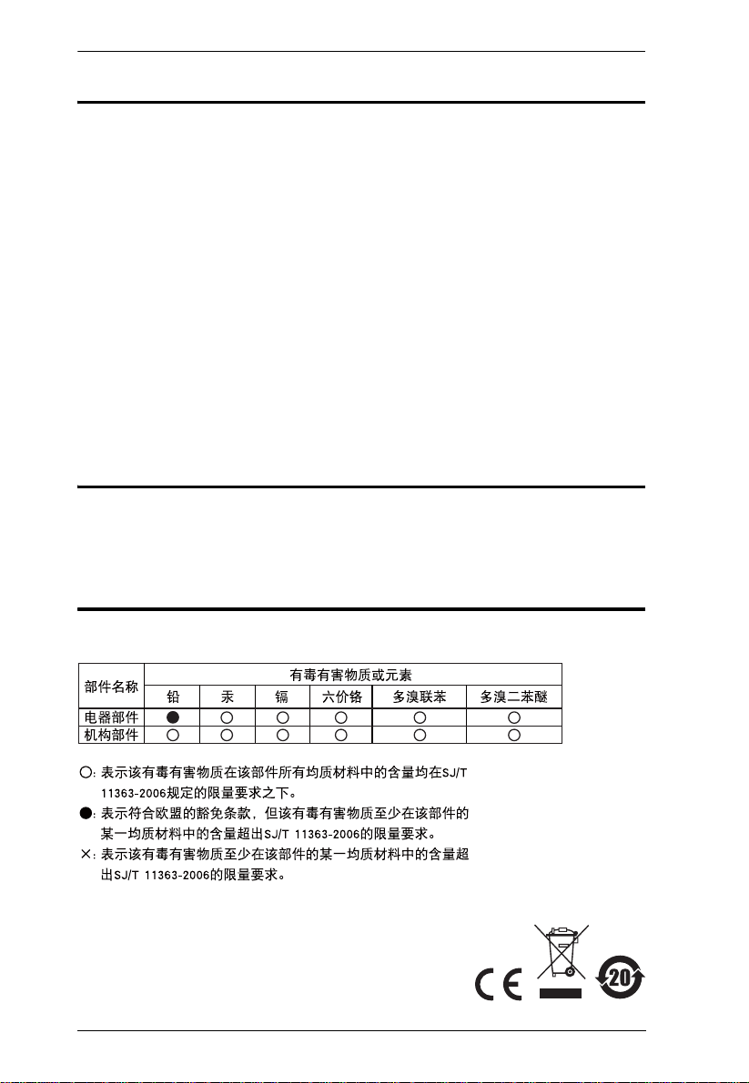
RoHS
This product is RoHS compliant.
SJ/T 11364-2006
The following contains information that relates to China.
ii
CL-1758 User Manual
User Information
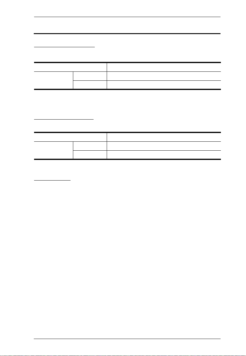
Online Registration
Be sure to register your product at our online support center:
International http://support.aten.com
North America ATEN TECH http://www.aten-usa.com/product_registration
ATEN NJ http://support.aten.com
Telephone Support
For telephone support, call this number:
International 886-2-8692-6959
North America ATEN TECH 1-888-999-ATEN
ATEN NJ 1-732-356-1703
User Notice
All information, documentation, and specifications contained in this manual
are subject to change without prior notification by the manufacturer. The
manufacturer makes no representations or warranties, either expressed or
implied, with respect to the contents hereof and specifically disclaims any
warranties as to merchantability or fitness for any particular purpose. Any of
the manufacturer's software described in this manual is sold or licensed as is.
Should the programs prove defective following their purchase, the buyer (and
not the manufacturer, its distributor, or its dealer), assumes the entire cost of all
necessary servicing, repair and any incidental or consequential damages
resulting from any defect in the software.
The manufacturer of this system is not responsible for any radio and/or TV
interference caused by unauthorized modifications to this device. It is the
responsibility of the user to correct such interference.
The manufacturer is not responsible for any damage incurred in the operation
of this system if the correct operational voltage setting was not selected prior
to operation. PLEASE VERIFY THAT THE VOLTAGE SETTING IS
CORRECT BEFORE USE.
iii

CL-1758 User Manual
© Copyright 2007 ATEN® International Co., Ltd.
Manual Part No. PAPE-0250-200G
Manual Date: 2008-12-08
ATEN and the ATEN logo are registered trademarks of ATEN Internatio nal Co., Ltd. All rights rese rved.
All other brand names and trademarks are the registered property of their respective owners.
Package Contents
Basic Package
The basic CL-1758 package consists of:
1 CL-1758 KVM Switch with Standard Rack Mounting Kit
2 Custom KVM Cable Sets
1 Firmware Upgrade Cable
1Power Cord
1 User Manual*
1 Quick Start Guide
Optional Equipment
Depending on any optional equipment that you may have purchased, one of the
following may be included in your package:
Standard Rack Mounting Kit - Long
Easy-Installation Rack Mounting Kit - Short
Easy-Installation Rack Mounting Kit - Long
Check to make sure that all the components are present and that nothing got
damaged in shipping. If you encounter a problem, contact your dealer.
Read this manual thoroughly and follow the installation and operation
procedures carefully to prevent any damage to the unit, and/or any of the
devices connected to it.
* Features may have been added to the CL-1758 since this manual was printed.
Please visit our website to download the most up-t o-date version of the
manual.
iv

CL-1758 User Manual
Contents
FCC Information . . . . . . . . . . . . . . . . . . . . . . . . . . . . . . . . . . . . . . . . . . . . .ii
RoHS. . . . . . . . . . . . . . . . . . . . . . . . . . . . . . . . . . . . . . . . . . . . . . . . . . . . . . ii
SJ/T 11364-2006. . . . . . . . . . . . . . . . . . . . . . . . . . . . . . . . . . . . . . . . . . . . .ii
User Information . . . . . . . . . . . . . . . . . . . . . . . . . . . . . . . . . . . . . . . . . . . . .iii
Online Registration . . . . . . . . . . . . . . . . . . . . . . . . . . . . . . . . . . . . . . . .iii
Telephone Support . . . . . . . . . . . . . . . . . . . . . . . . . . . . . . . . . . . . . . . .iii
User Notice . . . . . . . . . . . . . . . . . . . . . . . . . . . . . . . . . . . . . . . . . . . . . .iii
Package Contents. . . . . . . . . . . . . . . . . . . . . . . . . . . . . . . . . . . . . . . . . . . iv
Basic Package. . . . . . . . . . . . . . . . . . . . . . . . . . . . . . . . . . . . . . . . . . . iv
Optional Equipment. . . . . . . . . . . . . . . . . . . . . . . . . . . . . . . . . . . . . . . iv
About this Manual . . . . . . . . . . . . . . . . . . . . . . . . . . . . . . . . . . . . . . . . . . .viii
Conventions . . . . . . . . . . . . . . . . . . . . . . . . . . . . . . . . . . . . . . . . . . . . . . . ix
Product Information. . . . . . . . . . . . . . . . . . . . . . . . . . . . . . . . . . . . . . . . . . ix
1. Introduction
Overview. . . . . . . . . . . . . . . . . . . . . . . . . . . . . . . . . . . . . . . . . . . . . . . . . . .1
Features . . . . . . . . . . . . . . . . . . . . . . . . . . . . . . . . . . . . . . . . . . . . . . . . . . .3
Hardware Requirements. . . . . . . . . . . . . . . . . . . . . . . . . . . . . . . . . . . . . . .4
Computers. . . . . . . . . . . . . . . . . . . . . . . . . . . . . . . . . . . . . . . . . . . . . . .4
Cables. . . . . . . . . . . . . . . . . . . . . . . . . . . . . . . . . . . . . . . . . . . . . . . . . .4
Components . . . . . . . . . . . . . . . . . . . . . . . . . . . . . . . . . . . . . . . . . . . . . . . .5
Front View. . . . . . . . . . . . . . . . . . . . . . . . . . . . . . . . . . . . . . . . . . . . . . .5
Rear View . . . . . . . . . . . . . . . . . . . . . . . . . . . . . . . . . . . . . . . . . . . . . . .7
2. Hardware Setup
Before You Begin . . . . . . . . . . . . . . . . . . . . . . . . . . . . . . . . . . . . . . . . . . . .9
Standard Rack Mounting. . . . . . . . . . . . . . . . . . . . . . . . . . . . . . . . . . . . . .10
Single Stage Installation . . . . . . . . . . . . . . . . . . . . . . . . . . . . . . . . . . . . . .12
Single Stage Installation Diagram . . . . . . . . . . . . . . . . . . . . . . . . .13
Two Stage Installation. . . . . . . . . . . . . . . . . . . . . . . . . . . . . . . . . . . . . . . .14
Two Stage Installation Diagram. . . . . . . . . . . . . . . . . . . . . . . . . . .15
Three Stage Installation . . . . . . . . . . . . . . . . . . . . . . . . . . . . . . . . . . . . . .16
Three Stage Installation Diagram . . . . . . . . . . . . . . . . . . . . . . . . .17
3. Basic Operation
Opening the Console . . . . . . . . . . . . . . . . . . . . . . . . . . . . . . . . . . . . . . . .19
Closing the Console . . . . . . . . . . . . . . . . . . . . . . . . . . . . . . . . . . . . . . . . .20
Operating Precautions . . . . . . . . . . . . . . . . . . . . . . . . . . . . . . . . . . . . . . .21
LCD OSD Configuration . . . . . . . . . . . . . . . . . . . . . . . . . . . . . . . . . . . . . .22
The LCD Buttons. . . . . . . . . . . . . . . . . . . . . . . . . . . . . . . . . . . . . . . . .22
The Adjustment Settings. . . . . . . . . . . . . . . . . . . . . . . . . . . . . . . . . . . 23
Port Selection . . . . . . . . . . . . . . . . . . . . . . . . . . . . . . . . . . . . . . . . . . . . . .24
Manual. . . . . . . . . . . . . . . . . . . . . . . . . . . . . . . . . . . . . . . . . . . . . . . . .24
v

CL-1758 User Manual
OSD . . . . . . . . . . . . . . . . . . . . . . . . . . . . . . . . . . . . . . . . . . . . . . . . . .24
Hotkey. . . . . . . . . . . . . . . . . . . . . . . . . . . . . . . . . . . . . . . . . . . . . . . . .24
Hot Plugging. . . . . . . . . . . . . . . . . . . . . . . . . . . . . . . . . . . . . . . . . . . . . . . 25
Hot Plugging KVM Ports . . . . . . . . . . . . . . . . . . . . . . . . . . . . . . . . . . .25
Hot Plugging Console Ports . . . . . . . . . . . . . . . . . . . . . . . . . . . . . . . .25
Powering Off and Restarting. . . . . . . . . . . . . . . . . . . . . . . . . . . . . . . . . . .26
Port ID Numbering . . . . . . . . . . . . . . . . . . . . . . . . . . . . . . . . . . . . . . . . . .27
4. OSD Operation
OSD Overview . . . . . . . . . . . . . . . . . . . . . . . . . . . . . . . . . . . . . . . . . . . . . 29
OSD Navigation . . . . . . . . . . . . . . . . . . . . . . . . . . . . . . . . . . . . . . . . . . . .31
OSD Main Screen Headings. . . . . . . . . . . . . . . . . . . . . . . . . . . . . . . . . . .31
OSD Functions . . . . . . . . . . . . . . . . . . . . . . . . . . . . . . . . . . . . . . . . . . . . .32
F1 GOTO . . . . . . . . . . . . . . . . . . . . . . . . . . . . . . . . . . . . . . . . . . . . . .32
F2 LIST . . . . . . . . . . . . . . . . . . . . . . . . . . . . . . . . . . . . . . . . . . . . . . . .33
F3 SET . . . . . . . . . . . . . . . . . . . . . . . . . . . . . . . . . . . . . . . . . . . . . . . .34
F4 ADM. . . . . . . . . . . . . . . . . . . . . . . . . . . . . . . . . . . . . . . . . . . . . . . .36
F7 SCAN. . . . . . . . . . . . . . . . . . . . . . . . . . . . . . . . . . . . . . . . . . . . . . .39
5. Keyboard Port Operation
Invoking Hotkey Mode (HKM). . . . . . . . . . . . . . . . . . . . . . . . . . . . . . . . . . 41
When Hotkey Mode is active: . . . . . . . . . . . . . . . . . . . . . . . . . . . . 41
Hotkey Port Access . . . . . . . . . . . . . . . . . . . . . . . . . . . . . . . . . . . . . . . . .42
Selecting the Active Port. . . . . . . . . . . . . . . . . . . . . . . . . . . . . . . . . . .42
Auto Scanning. . . . . . . . . . . . . . . . . . . . . . . . . . . . . . . . . . . . . . . . . . .43
Invoking Auto Scan Mode: . . . . . . . . . . . . . . . . . . . . . . . . . . . . . .43
Pausing Auto Scan:. . . . . . . . . . . . . . . . . . . . . . . . . . . . . . . . . . . .43
Hotkey Configuration . . . . . . . . . . . . . . . . . . . . . . . . . . . . . . . . . . . . . . . .44
Alternate Hotkey Invocation Keys. . . . . . . . . . . . . . . . . . . . . . . . . . . .44
Alternate OSD Activation Keys . . . . . . . . . . . . . . . . . . . . . . . . . . . . . .44
Keyboard Operating Platform . . . . . . . . . . . . . . . . . . . . . . . . . . . . . . .45
Beeper Control . . . . . . . . . . . . . . . . . . . . . . . . . . . . . . . . . . . . . . . . . . 46
Restore Default Settings. . . . . . . . . . . . . . . . . . . . . . . . . . . . . . . . . . .46
Hotkey Summary Table . . . . . . . . . . . . . . . . . . . . . . . . . . . . . . . . . . . . . .47
6. Keyboard Emulation
Mac Keyboard. . . . . . . . . . . . . . . . . . . . . . . . . . . . . . . . . . . . . . . . . . . . . .49
Sun Keyboard. . . . . . . . . . . . . . . . . . . . . . . . . . . . . . . . . . . . . . . . . . . . . .50
7. The Firmware Upgrade Utility
Preparation. . . . . . . . . . . . . . . . . . . . . . . . . . . . . . . . . . . . . . . . . . . . . . . .52
Starting the Upgrade. . . . . . . . . . . . . . . . . . . . . . . . . . . . . . . . . . . . . . . . .53
Upgrade Succeeded . . . . . . . . . . . . . . . . . . . . . . . . . . . . . . . . . . . . . . 56
Upgrade Failed . . . . . . . . . . . . . . . . . . . . . . . . . . . . . . . . . . . . . . . . . .56
Firmware Upgrade Recovery . . . . . . . . . . . . . . . . . . . . . . . . . . . . . . . . . . 57
vi

CL-1758 User Manual
8. Appendix
Safety Instructions. . . . . . . . . . . . . . . . . . . . . . . . . . . . . . . . . . . . . . . . . . .59
General . . . . . . . . . . . . . . . . . . . . . . . . . . . . . . . . . . . . . . . . . . . . . . . .59
Rack Mounting . . . . . . . . . . . . . . . . . . . . . . . . . . . . . . . . . . . . . . . . . .61
Technical Support. . . . . . . . . . . . . . . . . . . . . . . . . . . . . . . . . . . . . . . . . . .62
International. . . . . . . . . . . . . . . . . . . . . . . . . . . . . . . . . . . . . . . . . . . . .62
North America . . . . . . . . . . . . . . . . . . . . . . . . . . . . . . . . . . . . . . . . . . .62
Specifications . . . . . . . . . . . . . . . . . . . . . . . . . . . . . . . . . . . . . . . . . . . . . .63
Connection Table . . . . . . . . . . . . . . . . . . . . . . . . . . . . . . . . . . . . . . . . . . .64
OSD Factory Default Settings. . . . . . . . . . . . . . . . . . . . . . . . . . . . . . . . . .65
Troubleshooting . . . . . . . . . . . . . . . . . . . . . . . . . . . . . . . . . . . . . . . . . . . .65
Clear Login Information. . . . . . . . . . . . . . . . . . . . . . . . . . . . . . . . . . . . . . .66
Optional Rack Mounting . . . . . . . . . . . . . . . . . . . . . . . . . . . . . . . . . . . . . . 67
Standard - Long: . . . . . . . . . . . . . . . . . . . . . . . . . . . . . . . . . . . . . .67
Easy Installation: . . . . . . . . . . . . . . . . . . . . . . . . . . . . . . . . . . . . . .67
Entering the ok Prompt (Sun Solaris) . . . . . . . . . . . . . . . . . . . . . . . . . . . .71
Dedicated Invocation Keys . . . . . . . . . . . . . . . . . . . . . . . . . . . . . . . . . . . .71
About SPHD Connectors . . . . . . . . . . . . . . . . . . . . . . . . . . . . . . . . . . . . .71
Limited Warranty. . . . . . . . . . . . . . . . . . . . . . . . . . . . . . . . . . . . . . . . . . . .72
vii

CL-1758 User Manual
About this Manual
This User Manual is provided to help you get the most from your c/c system.
It covers all aspects of installation, configuration and operation. An overview
of the information found in the manual is provided below.
Chapter 1, Introduction, introduces you to the CL-1758 system. Its
purpose, features and benefits are presented, and its front and back panel
components are described.
Chapter 2, Hardware Setup, describes how to set up your installation. The
necessary step –
chained operation are provided.
Chapter 3, Basic Operation, explains the fundamental concepts involved
in operating the CL-1758.
Chapter 4, OSD Operation, provides a complete description of the CL1758's OSD (On Screen Display), and how to work with it.
Chapter 5, Keyboard Port Operation, details all of the concepts and
procedures involved in the Hotkey operation of your CL-1758 installation.
Chapter 6, Keyboard Emulation, provides tables that list the PC to Mac
and PC to Sun keyboard emulation mappings.
from a basic single stage hookup to a complete 32 switch daisy
Chapter 7, The Firmware Upgrade Utility, explains how to use this
utility to upgrade the CL-1758's firmware with the latest available versions.
An Appendix, provides specifications and other technical information
regarding the CL-1758.
viii
Conventions
This manual uses the following conventions:
Monospaced Indicates text that you should key in.
[ ] Indicates keys you should press. For example, [Enter] means to
press the Enter key. If keys need to be chorded, they appear
together in the same bracket with a plus sign between them:
[Ctrl+Alt].
1. Numbered lists represent procedures with sequential steps.
♦ Bullet lists provide information, but do not involve sequential steps.
→ Indicates selecting the option (on a menu or dialog box, for
example), that comes next. For example, Start
open the Start menu, and then select Run.
Indicates critical information.
Product Information
CL-1758 User Manual
→ Run means to
For information about all ATEN products and how they can help you connect
without limits, visit ATEN on the Web or contact an ATEN Authorized
Reseller. Visit ATEN on the Web for a list of locations and telephone numbers:
International http://www.aten.com
North America ATEN TECH http://www.aten-usa.com
ATEN NJ http://www.aten.com
ix

CL-1758 User Manual
This Page Intentionally Left Blank
x

Chapter 1
Introduction
Overview
The Master View CL-1758 KVM Switch is a control unit that allows access to
multiple computers from a single keyboard, monitor, and mouse (KVM)
console. Before the development of the Master View, the only way to control
multiple computer configurations from a single console was through a complex
and costly network system. Now, with the Master View CL-1758, you can
easily access multiple computers in a cost effective manner.
A single Master View CL-1758 can control up to 8 computers. Since the
CL-1758 supports cascading to three levels, in a complete three stage
installation, up to 72 Master View CS-1758 models can be cascaded from the
CL-1758 to control up to 512 computers - all from the original single console.
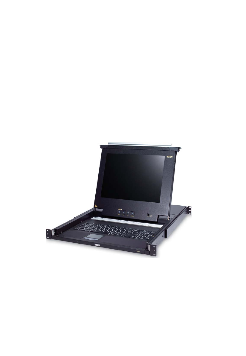
The Master View CL-1758 offers a space-saving, streamlined approach to
KVM switch technology by integrating a keyboard, LCD monitor, and
touchpad in a Slideaway™ housing. The LCD display is built into the cover;
the keyboard and touchpad are built into the base. Slide the KVM module
section out; flip the cover up; and you are ready to go to work. When finished,
flip the cover down and slide the KVM module away.
For further convenience and flexibility, the switch also supports an external
keyboard, monitor, and mouse console. Although external consoles often use a
PS/2 keyboard and mouse, the CL-1758 supports both PS/2 and USB
computers. Depending on the cable you use to link the switch to the computer,
you can attach to a computer with PS/2 connectors or USB connectors.
(See Cables, page 4, for more details.)
The Slideaway™ housing is 1U high for easy rack mounting, and because of
its modular design, the KVM section can be detached from the switch section.
The CL-1758 also features high density 15 pin KVM connectors instead of the
usual 25 pin kind. This space-saving innovation provides more reliable and
efficient transmission of KVM data, at the same time that it reduces cable
clutter.
Your CL-1758 investment is protected by an included Firmware Upgrade
Utility. You can stay current with the latest functionality improvements by
downloading firmware update files from our website as they become available,
and using the utility to quickly and conveniently perform the upgrade.
1

CL-1758 User Manual
Access to any computer connected to the installation is easily accomplished
either through a powerful, mouse driven, OSD (On Screen Display) menu
system, or by entering Hotkey combinations from the keyboard. A convenient
Auto Scan feature also permits automatic scanning and monitoring of the
activities of all computers running on the installation one by one.
Setup is fast and easy; simply plug cables into their appropriate ports. There is
no software to configure, no installation routines, and no incompatibil ity
problems. Since the CL-1758 intercepts keyboard input directly, it works on
multiple operating platforms (PC compatible, Mac*, Sun*, etc.).
There is no better way to save time and money than with a CL-1758
installation. Since a single console manages all of the computers, the CL-1758
setup: (1) eliminates the expense of having to purchase a separate keyboard,
monitor, and mouse for each computer; (2) saves all the space those extra
components would take up; (3) saves on energy costs; and (4) eliminates the
inconvenience and wasted effort involved in constantly moving from one
computer to another.
* Mac and Sun computers must use the USB cable connection (see p. 4).
2

Chapter 1. Introduction
Features
Integrated KVM console with 15"or 17" LCD monitor in a Slideaway™
housing.
Slideaway™ housing is less than 1 U – with top and bottom clearance for
smooth operation in a 1U high system rack.
Space saving technology - two consoles (one bus) controls 8 computers.
Cascadable to three levels for control of up to 512 computers from a single
console.
Dual interface support - PS/2 or USB keyboard and mouse data transfer
from the switch to the computer*
No software required - convenient computer selection via mouse driven
intuitive On Screen Display (OSD) menus and Hotkeys.
Auto Scan feature for monitoring user-selected computers.
Hot Pluggable - add or remove computers without having to power down
the switch.
Two level password security - only authorized users view and control the
computers - up to four users plus an administrator with separate profiles
for each.
DDC Emulation of the LCD Monitor - VGA settings of every connected
computer are automatically adjusted for optimal output to the LCD
Monitor.
Upgradable firmware.
Supports Windows, Mac, and Sun host systems
Windows 98SE / ME / 2000 / XP / 2003; Mac OS8.6 or higher; Solaris;
Linux
* For PC compatible computers only. Mac and Sun computers must use the
USB cable connection (see p. 4).
3
CL-1758 User Manual
Hardware Requirements
Computers
The following equipment must be installed on each computer:
A VGA, SVGA or Multisync card.
Note: The integrated LCD monitor's maximum resolution is 1024 x 768 @
75Hz (15") or 1280 x1024 @ 75Hz (17"). Make sure that the
computer resolution settings do not exceed the LCD monitor's
maximum resolution.
Either a Type A USB port, or PS/2 keyboard and mouse ports (see the
Cables discussion in the next section).
Cables
Only the following ATEN Custom KVM cable sets may be used with these
switches.
Depending on the KVM cable type, the switches can link to computers that use
PS/2 connectors to transfer keyboard and mouse data as well as computers that
use USB connectors (see the installation diagram on p. 12).
Function Part Number
KVM Switch to PS/2 Connectors
(See the note on p. 4)
KVM Switch to USB Connectors 2L-5201U - 1.2m
2L-5702P - 1.8m
2L-5201P - 1.2m
2L-5202P - 1.8m
2L-5203P - 3m
2L-5206P - 6m
2L-5202U - 1.8m
2L-5203U - 3m
2L-5206U - 6m
To purchase ATEN Custom KVM cable sets, contact your dealer.
Note: 1. Two cables are provided with this package.
2. For PS/2 port computers, we strongly recommend using 2L-5702P
cables. While the other cables work, the keyboard and/or mouse will
not work if all their connectors (keyboard, video, and mouse), aren't
plugged into their ports on the computer before starting the computer
up. The 2L-5702P cables do not have this limitation.
4
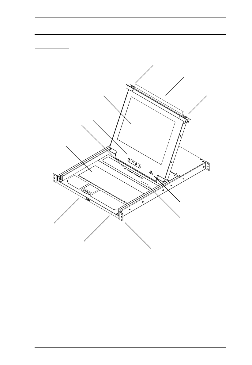
Components
2
3
6
12
9
10 & 11
1
13
13
7
8
4 & 5
Front View
Chapter 1. Introduction
(Continues on next page.)
5

CL-1758 User Manual
(Continued from previous page.)
No. Component Description
1 Handle Pull to slide the KVM module out; push to slide the module in
2 LCD Display After sliding the KVM module out, flip up the cover to access
3 LCD Controls The LCD On/Off switch is located here, as well as buttons to
4 Port Switches Press a switch to bring the KVM focus to the computer
5 Port LEDs Two Port LEDs are built into the Port Switches. The one on
(see item 13 in this table).
the LCD monitor.
control the position and picture settings of the LCD display.
See p. 22, for details.
attached to its corresponding port. See p. 24 for details.
the left is the On Line LED; the one on the right is the
Selected Port LED:
An On Line LED lights ORANGE to indicate that the com-
puter attached to its corresponding port is up and running.
A Selected LED lights GREEN to indicate that the com-
puter attached to its corresponding port is the one that has
the KVM focus. The LED is steady under normal conditions, but flashes when its port is accessed under Auto
Scan Mode (see p. 39).
6 Keyboard
7Touchpad
8 Power LED Lights BLUE to indicate that the unit is receiving power.
9 Rack Mounting
Brackets
10 Lock LEDs The Num Lock, Caps Lock, Scroll Lock LEDs are located
11 Reset Switch Located to the right of the Lock LEDs. Press this recessed
12 Firmware
Upgrade Section
The rack mounting brackets located at each corner of the unit
secure the chassis to a system rack. Refer to the Appendix
(p. 67), for rack mounting details.
here.
switch in with a thin object to perform a system reset.
Firmware Upgrade Port: The Firmware Upgrade Cable
that transfers the firmware upgrade data from the adminis-
trator's computer to the CL-1758 plugs into this RJ-11 con-
nector.
Firmware Upgrade Switch: During normal operation this
switch should be in the NORMAL position. (See p. 51 for
firmware upgrading details.)
13 Slide Release In order to slide the console out, you must first release it by
sliding these tabs to the inside. See page 19 for details on
sliding the console in and out.
6
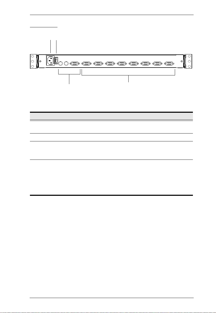
Rear View
1
Chapter 1. Introduction
2
3
No. Component Description
1 Power Socket This is a standard 3 prong AC power socket. The power cord
from an AC source plugs in here.
2 Power Switch
3 External
Console Section
4 KVM Port
Section
For flexibility and convenience, the CL-1758 supports an
independent, external, KVM console. The external console's
keyboard, monitor, and mouse cables plug in here.
The cables that link to the computers plug in here.
Note: The shape of these 15-pin connectors has been
specifically modified so that only KVM cables designed to
work with this switch can plug in (see the Cables section on
p. 4, for details). Do NOT attempt to use ordinary 15 pin VGA
connector cables to link these ports to the computers.
4
7

CL-1758 User Manual
This Page Intentionally Left Blank
8

Before You Begin
1. Important safety information regarding the placement of this
device is provided on page 59. Please review it before
proceeding.
2. Make sure that the power to any device that you connect to the
installation has been turned off. You must unplug the power
cords of any computers that have the Keyboard Power On
Chapter 2
Hardware Setup
9
CL-1758 User Manual
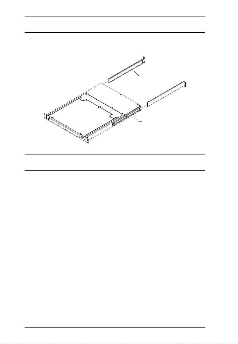
L Brackets
Side Mountng
Brackets
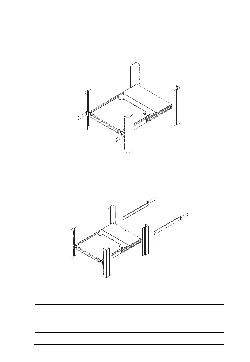
Standard Rack Mounting
A standard rack mounting kit is provided with your CL-1758. The kit enables
the switch to be mounted in rack with a depth of 42.0 - 82.0 cm.
Note: It takes two people to mount the switch: one to hold it in place; the other
to screw it in.
Optional mounting kits - including single person Easy Installation kits - are
available with a separate purchase. See Optional Rack Mounting, page 67 for
optional rack mounting details.
10
Chapter 2. Hardware Setup
To rack mount the switch, do the following:
1. While one person positions the switch in the rack and holds it in place, the
second person - using the screws provided with the rack mounting kit loosely screws the front brackets to the rack.
2. While the first person still holds the switch in place, the second person
slides the L brackets into the switch's side mounting brackets, from the
rear until the bracket flanges contact the rack, then - using the screws
provided with the rack mounting kit - screws the L brackets to the rack.
3. After the L brackets have been secured, tighten the front bracket screws.
Note: 1. Cage nuts are provided for racks that are not prethreaded.
2. Allow at least 5.1 cm on each side for proper ventilation, and at least
12.7 cm at the back for the power cord and cable clearance.
11

CL-1758 User Manual
Single Stage Installation
To set up a single stage installation, refer to the installation diagram on the next
page (the numbers in the diagram correspond to the numbers of the installation
steps), and do the following:
1. If you choose to install an external console, plug your keyboard, monitor,
and mouse into the Console Ports located on the switch's rear panel. The
ports are color coded and marked with an appropriate icon to indicate
themselves.
2. Using a KVM cable set (described in the Cables section on p. 4), plug the
custom SPHD connector into any available KVM Port on the switch.
3. At the other end of the cable:
a) For a USB connection, plug the USB and video connectors into their
respective ports on the computer.
b) For a PS/2 connection plug the keyboard, mouse and video connectors
into their respective ports on the computer.
Note: Repeat steps 2 and 3 for any additional computers you are installing.
4. Use the Power cord provided with this package to connect the switch's
Power Socket to an AC power source.
This completes the single stage installation, and you can power on the switch.
After the switch has been powered on, you can turn on the power to the
computers.
Note: The CL-1758 initially links to the first port when you turn it on.
12
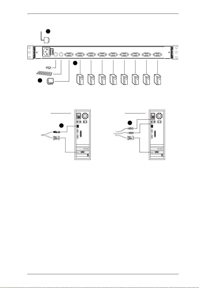
Single Stage Installation Diagram
3
USB Connection
3
PS/2 Connection
1
2
4
Chapter 2. Hardware Setup
13

CL-1758 User Manual
Two Stage Installation
To control even more computers, up to eight additional Master View CS-1758
units can be cascaded from the KVM ports of the First Stage unit. The cascaded
Master Views that connect back to the First Stage unit are considered Second
Stage units. As many as 64 computers can be controlled in a complete two
stage installation. A table showing the relation between the number of
computers and the number of units needed to control them is provided on
page 64.
To set up a two stage installation, refer to the Two Stage Installation diagram
on the next page as you do the following:
1. Make sure that power to all the devices you will be connecting up,
including all preexisting devices on the installation, have been turned off.
2. Use a USB KVM cable set (see Cables, page 4), to connect any available
KVM Port on the First Stage unit to the Console ports of the Second Stage
unit.
Note: Plug the USB connector into the USB port next to the Console
SPHD port (they are both marked with a similar icon to remind you
of the correct USB port).
3. Using a KVM cable set (see Cables, page 4), plug the custom SPHD
connector into any available KVM Port on the switch.
Note: The CL-1758 does not support the audio features of audio enabled
KVM switches.
4. At the other end of the cable:
a) For a USB connection (see p. 12), plug the USB and video connectors
into their respective ports on the computer.
b) For a PS/2 connection (see p. 12), plug the keyboard, mouse, and video
connectors into their respective ports on the computer.
5. Repeat steps 3 and 4 for any other computers you are connecting up.
6. For each Second Stage unit, plug the power adapter cable into its Power
Jack, then plug the power adapter into an AC source.
7. Power On the First Stage unit.
8. Turn on the power to all the computers.
14
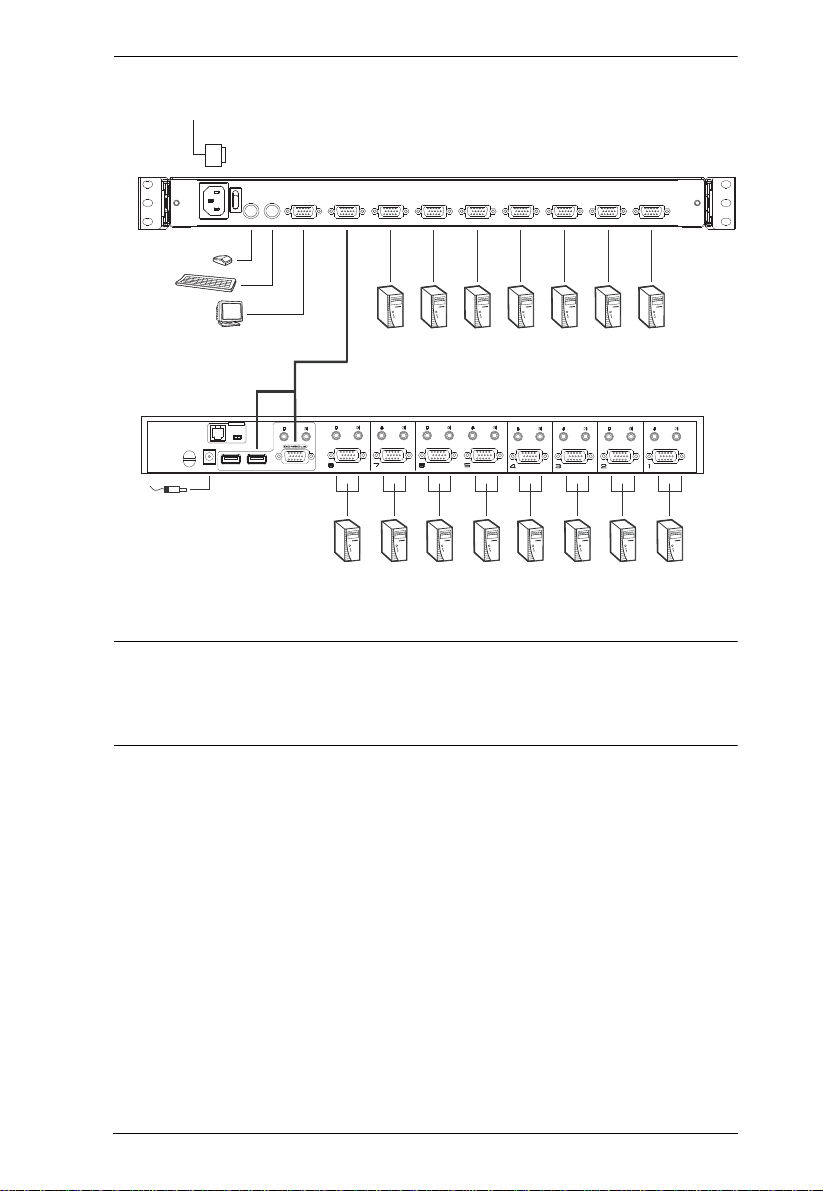
Two Stage Installation Diagram
CL-1758
Chapter 2. Hardware Setup
CS-1758
F/W UPGRADE
NORMAL RECOVER
Note: The Power On sequence requires that all Second Stage units be powered
on first. After all the Second Stage units have been powered on, then the
First Stage unit must be powered on next. After the Second and First
stage units have been powered on, the computers can be powered on.
15

CL-1758 User Manual
Three Stage Installation
The procedures for setting up a three stage installation are essentially the same
as for a two stage installation. With a three stage setup, as many as 512
computers can be controlled in a complete installation. A table showing the
relation between the number of computers and the number of switches needed
to control them is provided on page 64.
Note: Switches cannot be cascaded beyond the third level.
To set up a three stage installation, refer to the Three Stage Installation diagram
on the next page. Once you have finished cabling up (see Two Stage
Installation for details, if necessary), power up according to the following
sequence:
1. For each Third Stage unit, plug the power adapter cable into the switch's
Power Jack; plug the power adapter into an AC source.
2. For each Second Stage unit, plug the power adapter cable into the switch's
Power Jack; plug the power adapter into an AC source.
3. Power On the First Stage unit.
4. Turn on the power to all the computers.
Note: The Power On sequence requires that all Third Stage units be powered
on first. After they are all on, the Second Stage units must be powered
on next. After all the Second Stage units are on, the First Stage unit must
be powered on. Only after all the switches have been powered on in this
sequence, can the computers be powered on.
16
 Loading...