

Page 1

LCD KVM Switch
CL1308 / CL1316
User Manual
www.aten.com
Page 2
CL1308 / CL1316 User Manual
FCC, CE Information
FEDERAL COMMUNICATIONS COMMISSION INTERFERENCE
STATEMENT: This equipment has been tested and found to comply with the
limits for a Class A digital device, pursuant to Part 15 of the FCC Rules. These
limits are designed to provide reasonable protection against harmful
interference when the equipment is operated in a commercial environment.
This equipment generates, uses, and can radiate radio frequency energy and, if
not installed and used in accordance with the instruction manual, may cause
harmful interference to radio communications. Operation of this equipment in
a residential area is likely to cause harmful interference in which case the user
will be required to correct the interference at his own expense.
FCC Caution: Any changes or modifications not expressly approved by the
party responsible for compliance could void the user's authority to operate this
equipment.
CE Warning: This is a class A product. In a domestic environment this product
may cause radio interference in which case the user may be required to take
adequate measures.
RoHS
This product is RoHS compliant.
SJ/T 11364-2006
The following contains information that relates to China.
ii
Page 3

CL1308 / CL1316 User Manual
User Information
Online Registration
Be sure to register your product at our online support center:
International http://eservice.aten.com
Telephone Support
For telephone support, call this number:
International 886-2-8692-6959
China 86-10-5255-0110
Japan 81-3-5615-5811
Korea 82-2-467-6789
North America 1-888-999-ATEN ext 4988
United Kingdom 44-8-4481-58923
User Notice
All information, documentation, and specifications contained in this manual
are subject to change without prior notification by the manufacturer. The
manufacturer makes no representations or warranties, either expressed or
implied, with respect to the contents hereof and specifically disclaims any
warranties as to merchantability or fitness for any particular purpose. Any of
the manufacturer's software described in this manual is sold or licensed as is.
Should the programs prove defective following their purchase, the buyer (and
not the manufacturer, its distributor, or its dealer), assumes the entire cost of all
necessary servicing, repair and any incidental or consequential damages
resulting from any defect in the software.
The manufacturer of this system is not responsible for any radio and/or TV
interference caused by unauthorized modifications to this device. It is the
responsibility of the user to correct such interference.
The manufacturer is not responsible for any damage incurred in the operation
of this system if the correct operational voltage setting was not selected prior
to operation. PLEASE VERIFY THAT THE VOLTAGE SETTING IS
CORRECT BEFORE USE.
iii
Page 4

CL1308 / CL1316 User Manual
© Copyright 2014 ATEN® International Co., Ltd.
Manual Part No.
F/W Version: V1.0.072
Manual Date: 2014-06-25
ATEN and the ATEN logo are registered trademarks of ATEN International Co., Ltd. All rights reserved.
All other brand names and trademarks are the registered property of their respective owners.
Package Contents
The CL1308 / CL1316 package consists of:
1 CL1308 / CL1316 LCD KVM Switch with Rack Mount Kit
1 Power Cord
2 Custom KVM Cables
1 Firmware Upgrade cable
1 User Instructions*
Check to make sure that all the components are present and that nothing got
damaged in shipping. If you encounter a problem, contact your dealer.
Read this manual thoroughly and follow the installation and operation
procedures carefully to prevent any damage to the unit, and/or any of the
devices connected to it.
* Features may have been added to the CL1308 / CL1316 since this manual
was published. Please visit our website to download the most up-to-date
version of the manual.
iv
Page 5

CL1308 / CL1316 User Manual
Contents
FCC, CE Information. . . . . . . . . . . . . . . . . . . . . . . . . . . . . . . . . . . . . . . . . . ii
RoHS. . . . . . . . . . . . . . . . . . . . . . . . . . . . . . . . . . . . . . . . . . . . . . . . . . . . . . ii
SJ/T 11364-2006. . . . . . . . . . . . . . . . . . . . . . . . . . . . . . . . . . . . . . . . . . . . . ii
User Information . . . . . . . . . . . . . . . . . . . . . . . . . . . . . . . . . . . . . . . . . . . . .iii
Online Registration . . . . . . . . . . . . . . . . . . . . . . . . . . . . . . . . . . . . . . . .iii
Telephone Support . . . . . . . . . . . . . . . . . . . . . . . . . . . . . . . . . . . . . . . .iii
User Notice . . . . . . . . . . . . . . . . . . . . . . . . . . . . . . . . . . . . . . . . . . . . . .iii
Package Contents. . . . . . . . . . . . . . . . . . . . . . . . . . . . . . . . . . . . . . . . . . . iv
About this Manual . . . . . . . . . . . . . . . . . . . . . . . . . . . . . . . . . . . . . . . . . . .viii
Conventions . . . . . . . . . . . . . . . . . . . . . . . . . . . . . . . . . . . . . . . . . . . . . . . ix
Product Information. . . . . . . . . . . . . . . . . . . . . . . . . . . . . . . . . . . . . . . . . . ix
1. Introduction
Overview . . . . . . . . . . . . . . . . . . . . . . . . . . . . . . . . . . . . . . . . . . . . . . . . . . .1
Features . . . . . . . . . . . . . . . . . . . . . . . . . . . . . . . . . . . . . . . . . . . . . . . . . . .2
Requirements . . . . . . . . . . . . . . . . . . . . . . . . . . . . . . . . . . . . . . . . . . . . . . . 3
Computers. . . . . . . . . . . . . . . . . . . . . . . . . . . . . . . . . . . . . . . . . . . . . . .3
Cables . . . . . . . . . . . . . . . . . . . . . . . . . . . . . . . . . . . . . . . . . . . . . . . . . .3
Operating Systems . . . . . . . . . . . . . . . . . . . . . . . . . . . . . . . . . . . . . . . . 4
Components . . . . . . . . . . . . . . . . . . . . . . . . . . . . . . . . . . . . . . . . . . . . . . . . 5
Front View . . . . . . . . . . . . . . . . . . . . . . . . . . . . . . . . . . . . . . . . . . . . . . .5
Rear View . . . . . . . . . . . . . . . . . . . . . . . . . . . . . . . . . . . . . . . . . . . . . . .7
2. Hardware Setup
Overview . . . . . . . . . . . . . . . . . . . . . . . . . . . . . . . . . . . . . . . . . . . . . . . . . . .9
Before you Begin. . . . . . . . . . . . . . . . . . . . . . . . . . . . . . . . . . . . . . . . . . . . .9
Standard Rack Mounting. . . . . . . . . . . . . . . . . . . . . . . . . . . . . . . . . . . . . .10
Grounding . . . . . . . . . . . . . . . . . . . . . . . . . . . . . . . . . . . . . . . . . . . . . . . . .12
Single Level Installation . . . . . . . . . . . . . . . . . . . . . . . . . . . . . . . . . . . . . . 13
Cable Connection Diagrams . . . . . . . . . . . . . . . . . . . . . . . . . . . . . . . . . . .14
Two Level Installation . . . . . . . . . . . . . . . . . . . . . . . . . . . . . . . . . . . . . . . .15
3. Basic Operation
Opening the Console . . . . . . . . . . . . . . . . . . . . . . . . . . . . . . . . . . . . . . . . 17
Closing the Console . . . . . . . . . . . . . . . . . . . . . . . . . . . . . . . . . . . . . . . . .18
Operating Precautions . . . . . . . . . . . . . . . . . . . . . . . . . . . . . . . . . . . . . . . 19
Powering Off and Restarting. . . . . . . . . . . . . . . . . . . . . . . . . . . . . . . . . . .20
LCD OSD Configuration . . . . . . . . . . . . . . . . . . . . . . . . . . . . . . . . . . . . . .21
The LCD Buttons. . . . . . . . . . . . . . . . . . . . . . . . . . . . . . . . . . . . . . . . .21
LCD Adjustment Settings . . . . . . . . . . . . . . . . . . . . . . . . . . . . . . . . . .22
Hot Plugging . . . . . . . . . . . . . . . . . . . . . . . . . . . . . . . . . . . . . . . . . . . . . . .23
Hot Plugging KVM Ports . . . . . . . . . . . . . . . . . . . . . . . . . . . . . . . . . . .23
Port Selection . . . . . . . . . . . . . . . . . . . . . . . . . . . . . . . . . . . . . . . . . . . . . . 23
Manual Port Switching. . . . . . . . . . . . . . . . . . . . . . . . . . . . . . . . . . . . . 23
Port ID Numbering . . . . . . . . . . . . . . . . . . . . . . . . . . . . . . . . . . . . . . . . . .24
v
Page 6

CL1308 / CL1316 User Manual
4. OSD Operation
OSD Overview . . . . . . . . . . . . . . . . . . . . . . . . . . . . . . . . . . . . . . . . . . . . . 25
OSD Login. . . . . . . . . . . . . . . . . . . . . . . . . . . . . . . . . . . . . . . . . . . . . . 25
OSD Hotkey . . . . . . . . . . . . . . . . . . . . . . . . . . . . . . . . . . . . . . . . . . . . 25
OSD Main Screen . . . . . . . . . . . . . . . . . . . . . . . . . . . . . . . . . . . . . . . . 26
OSD Main Screen Headings. . . . . . . . . . . . . . . . . . . . . . . . . . . . . . . . 26
OSD Navigation . . . . . . . . . . . . . . . . . . . . . . . . . . . . . . . . . . . . . . . . . 27
OSD Functions . . . . . . . . . . . . . . . . . . . . . . . . . . . . . . . . . . . . . . . . . . . . . 27
F1: GOTO . . . . . . . . . . . . . . . . . . . . . . . . . . . . . . . . . . . . . . . . . . . . . . 28
F2: LIST . . . . . . . . . . . . . . . . . . . . . . . . . . . . . . . . . . . . . . . . . . . . . . . 28
F3: SET. . . . . . . . . . . . . . . . . . . . . . . . . . . . . . . . . . . . . . . . . . . . . . . . 29
F4: ADM . . . . . . . . . . . . . . . . . . . . . . . . . . . . . . . . . . . . . . . . . . . . . . . 31
F5: SKP. . . . . . . . . . . . . . . . . . . . . . . . . . . . . . . . . . . . . . . . . . . . . . . . 34
F6: BRC . . . . . . . . . . . . . . . . . . . . . . . . . . . . . . . . . . . . . . . . . . . . . . . 34
F7: SCAN . . . . . . . . . . . . . . . . . . . . . . . . . . . . . . . . . . . . . . . . . . . . . . 35
F8: LOUT . . . . . . . . . . . . . . . . . . . . . . . . . . . . . . . . . . . . . . . . . . . . . . 36
5. Keyboard Port Operation
Hotkey Port Control . . . . . . . . . . . . . . . . . . . . . . . . . . . . . . . . . . . . . . . . . 37
Invoke Hotkey Mode . . . . . . . . . . . . . . . . . . . . . . . . . . . . . . . . . . . . . . . . . 37
Number Lock and Minus Keys . . . . . . . . . . . . . . . . . . . . . . . . . . . 37
Control and F12 Keys . . . . . . . . . . . . . . . . . . . . . . . . . . . . . . . . . . 38
Select the Active Port . . . . . . . . . . . . . . . . . . . . . . . . . . . . . . . . . . . . . . . . 38
Auto Scan Mode . . . . . . . . . . . . . . . . . . . . . . . . . . . . . . . . . . . . . . . . . . . . 39
Invoking Auto Scan: . . . . . . . . . . . . . . . . . . . . . . . . . . . . . . . . . . . . . . 39
Skip Mode. . . . . . . . . . . . . . . . . . . . . . . . . . . . . . . . . . . . . . . . . . . . . . . . . 40
Computer Keyboard / Mouse Reset . . . . . . . . . . . . . . . . . . . . . . . . . . . . . 41
Hotkey Beeper Control . . . . . . . . . . . . . . . . . . . . . . . . . . . . . . . . . . . . . . . 41
Quick Hotkey Control . . . . . . . . . . . . . . . . . . . . . . . . . . . . . . . . . . . . . . . . 42
OSD Hotkey Control . . . . . . . . . . . . . . . . . . . . . . . . . . . . . . . . . . . . . . . . . 42
Port OS Control . . . . . . . . . . . . . . . . . . . . . . . . . . . . . . . . . . . . . . . . . . . . 43
Restore Default Values. . . . . . . . . . . . . . . . . . . . . . . . . . . . . . . . . . . . . . . 43
Hotkey Summary Table . . . . . . . . . . . . . . . . . . . . . . . . . . . . . . . . . . . . . . 44
6. The Firmware Upgrade Utility
Introduction . . . . . . . . . . . . . . . . . . . . . . . . . . . . . . . . . . . . . . . . . . . . . . . . 45
Downloading the Firmware Upgrade Package . . . . . . . . . . . . . . . . . . 45
Preparation . . . . . . . . . . . . . . . . . . . . . . . . . . . . . . . . . . . . . . . . . . . . . . . . 46
Starting the Upgrade. . . . . . . . . . . . . . . . . . . . . . . . . . . . . . . . . . . . . . . . . 47
Upgrade Succeeded . . . . . . . . . . . . . . . . . . . . . . . . . . . . . . . . . . . . . . . . . 49
Upgrade Failed . . . . . . . . . . . . . . . . . . . . . . . . . . . . . . . . . . . . . . . . . . . . . 49
Firmware Upgrade Recovery . . . . . . . . . . . . . . . . . . . . . . . . . . . . . . . . . . 50
7. Keyboard Emulation
Mac Keyboard. . . . . . . . . . . . . . . . . . . . . . . . . . . . . . . . . . . . . . . . . . . . . . 51
Sun Keyboard . . . . . . . . . . . . . . . . . . . . . . . . . . . . . . . . . . . . . . . . . . . . . . 52
vi
Page 7

CL1308 / CL1316 User Manual
Appendix
Safety Instructions. . . . . . . . . . . . . . . . . . . . . . . . . . . . . . . . . . . . . . . . . . .53
General . . . . . . . . . . . . . . . . . . . . . . . . . . . . . . . . . . . . . . . . . . . . . . . .53
Rack Mounting . . . . . . . . . . . . . . . . . . . . . . . . . . . . . . . . . . . . . . . . . .55
Consignes de sécurité. . . . . . . . . . . . . . . . . . . . . . . . . . . . . . . . . . . . . . . .56
Général . . . . . . . . . . . . . . . . . . . . . . . . . . . . . . . . . . . . . . . . . . . . . . . .56
Montage sur bâti . . . . . . . . . . . . . . . . . . . . . . . . . . . . . . . . . . . . . . . . .58
Technical Support . . . . . . . . . . . . . . . . . . . . . . . . . . . . . . . . . . . . . . . . . . .60
International. . . . . . . . . . . . . . . . . . . . . . . . . . . . . . . . . . . . . . . . . . . . . 60
North America . . . . . . . . . . . . . . . . . . . . . . . . . . . . . . . . . . . . . . . . . . .60
Specifications . . . . . . . . . . . . . . . . . . . . . . . . . . . . . . . . . . . . . . . . . . . . . .61
Connection Tables . . . . . . . . . . . . . . . . . . . . . . . . . . . . . . . . . . . . . . . . . .62
CL1308 to Compatible 8-Port Switches . . . . . . . . . . . . . . . . . . . . . . .62
CL1308 to Compatible 16-Port Switches . . . . . . . . . . . . . . . . . . . . . .62
CL1316 to Compatible 8-Port Switches . . . . . . . . . . . . . . . . . . . . . . .62
CL1316 to Compatible 16-Port Switches . . . . . . . . . . . . . . . . . . . . . .62
Supported KVM Switches . . . . . . . . . . . . . . . . . . . . . . . . . . . . . . . . . . . . .63
OSD Factory Default Settings. . . . . . . . . . . . . . . . . . . . . . . . . . . . . . . . . .64
Optional Rack Mounting . . . . . . . . . . . . . . . . . . . . . . . . . . . . . . . . . . . . . .65
Standard - Long . . . . . . . . . . . . . . . . . . . . . . . . . . . . . . . . . . . . . . .65
Easy Installation. . . . . . . . . . . . . . . . . . . . . . . . . . . . . . . . . . . . . . .65
About SPHD Connectors . . . . . . . . . . . . . . . . . . . . . . . . . . . . . . . . . . . . .68
Troubleshooting . . . . . . . . . . . . . . . . . . . . . . . . . . . . . . . . . . . . . . . . . . . .69
Limited Warranty . . . . . . . . . . . . . . . . . . . . . . . . . . . . . . . . . . . . . . . . . . . . 69
vii
Page 8

CL1308 / CL1316 User Manual
About this Manual
This user manual is provided to help you get the most from your CL1308 /
CL1316 system. It covers all aspects of installation, configuration and
operation. An overview of the information found in the manual is provided
below.
Chapter 1, Introduction, introduces you to the CL1308 / CL1316 system.
Its purpose, features and benefits are presented, and its front and back panel
components are described.
Chapter 2, Hardware Setup, describes how to set up your installation. The
necessary steps – from a basic single level hookup to a complete 17-switch two
level operation are provided.
Chapter 3, Basic Operation, explains the fundamental concepts involved
in operating the CL1308 / CL1316.
Chapter 4, OSD Operation, provides a complete description of the
CL1308 / CL1316 OSD (on-screen display), and how to work with it.
Chapter 5, Keyboard Port Operation, details all of the concepts and
procedures involved in the hotkey operation of your CL1308 / CL1316
installation.
Chapter 7, Keyboard Emulation, provides tables that list the PC to Mac
and PC to Sun keyboard emulation mappings.
Chapter 6, The Firmware Upgrade Utility, explains how to use this
utility to upgrade the CL1308 / CL1316 firmware with the latest available
versions.
An Appendix, provides specifications and other technical information
regarding the CL1308 / CL1316.
viii
Page 9

Conventions
This manual uses the following conventions:
Monospaced Indicates text that you should key in.
[ ] Indicates keys you should press. For example, [Enter] means to
press the Enter key. If keys need to be chorded, they appear
together in the same bracket with a plus sign between them:
[Ctrl+Alt].
1. Numbered lists represent procedures with sequential steps.
♦ Bullet lists provide information, but do not involve sequential steps.
→ Indicates selecting the option (on a menu or dialog box, for
example), that comes next. For example, Start
open the Start menu, and then select Run.
Indicates critical information.
Product Information
CL1308 / CL1316 User Manual
→ Run means to
For information about all ATEN products and how they can help you connect
without limits, visit ATEN on the Web or contact an ATEN Authorized
Reseller. Visit ATEN on the Web for a list of locations and telephone numbers:
International http://www.aten.com
North America http://www.aten-usa.com
ix
Page 10

CL1308 / CL1316 User Manual
This Page Intentionally Left Blank
x
Page 11

Chapter 1
Introduction
Overview
The CL1308 / CL1316 LCD KVM Switch features an integrated 19" LCD
panel allowing access and control with up to 8 or 16 computers from a single
console (keyboard, mouse, and monitor). As many as 8 (CL1308) or 16
(CL1316) additional switches can be cascaded bringing the total number of
connected computers to 128 (CL1308) or 256 (CL1316) computers that can be
controlled from a single keyboard-monitor-mouse console. Additionally, the
CL1308 / CL1316 features a compact design that allows installation in a 1U
system rack.
Setup is fast and easy; plugging cables into their appropriate ports is all that is
needed. The switch supports both USB and PS/2 connections for the console
and computers. The CL1308 / CL1316 intercepts keyboard input directly, thus
eliminating the need for any software configuration. Switching between
computers can be easily accomplished either by manually pressing the front
panel push button port LEDs, entering hotkey combinations from the
keyboard, or via a menu driven multilingual on-screen display (OSD) system.
A convenient auto-scan feature permits automatic scanning and monitoring of
activities on all connected computers. Lastly, the CL1308 / CL1316 offers the
following additional benefits: a) integrated 19” LCD, keyboard and mouse
console, b) managing 8/16 computers from a single console, c) eliminating the
expense of having to purchase a separate keyboard, monitor, and mouse for
each computer, d) space and energy costs savings, and d) creates a greener
environment by reducing energy waste.
1
Page 12

CL1308 / CL1316 User Manual
Features
A single console controls up to 128 (CL1308) or 256 (CL1316) computers
Integrated KVM console with 19” LCD panel
Cascade to 2 levels – connect up to 8 (CL1308) or 16 (CL1316) switches
Dual Interface – supports computers with PS/2 or USB keyboards and
mice
Multiplatform support – Windows 2000/XP/Vista, Linux, Mac, and Sun
Supports USB keyboards for PC, Mac and Sun
Auto PS/2 and USB interface detection
USB or PS/2 keyboard and mouse emulation – computers boot even when
the console focus is elsewhere
Superior video quality – up to 1280 x 1024 @ 75 Hz; DDC2B
Convenient computer switching via front panel pushbuttons, hotkeys, or
multilingual on-screen display (OSD) menu
Two level password security - only authorized users view and control
computers; up to four users and an administrator with a separate profile for
each
Auto Scan feature for monitoring user-selected computers
Broadcast mode – operations simultaneously performed on all selected
computers
Hot pluggable – add or remove computers without having to power down
the switch
Buzzer on/off via hotkey and OSD
Firmware upgradeable
No software installation required
Rack mountable
2
Page 13
Chapter 1. Introduction
Requirements
Computers
The following hardware components are required for each computer:
A VGA, SVGA, or multisync video graphics card with an HDB-15 port.
PS/2 mouse and keyboard ports (6-pin Mini-DIN), or at least one USB
port.
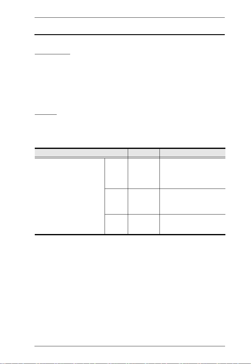
Cables
Substandard cables might damage the connected devices or degrade overall
performance. For optimum signal integrity and to simplify the layout use the
high quality custom cable sets described below.
Function Length Part Number
KVM switch to computer PS/2 1.2 m
USB 1.2 m
USB and
PS/2
1.8 m
3.0 m
6.0 m
1.8 m
1.8 m
3.0 m
5.0 m
1.2 m
1.8 m
3.0 m
2L-5201P
2L-5202P
2L-5203P
2L-5206P
2L-5702P
2L-5201U
2L-5202U
2L-5203U
2L-5205U
2L-5301UP
2L-5302UP
2L-5303UP
3
Page 14
CL1308 / CL1316 User Manual
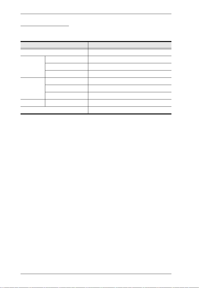
Operating Systems
Supported operating systems are shown in the table, below:
OS Ver sio n
Windows 2000 and higher
Linux RedHat 7.1 and higher
SuSE 8.2 and higher
Mandriva (Mandrake) 9.0 and higher
UNIX AIX 4.3 and higher
FreeBSD 4.2 and higher
Sun Solaris 8 and higher
Novell Netware 5.0 and higher
Mac OS 9 and higher
4
Page 15
Components
2
1
2
3
4
5
6
7
8
9
10
11
12
13
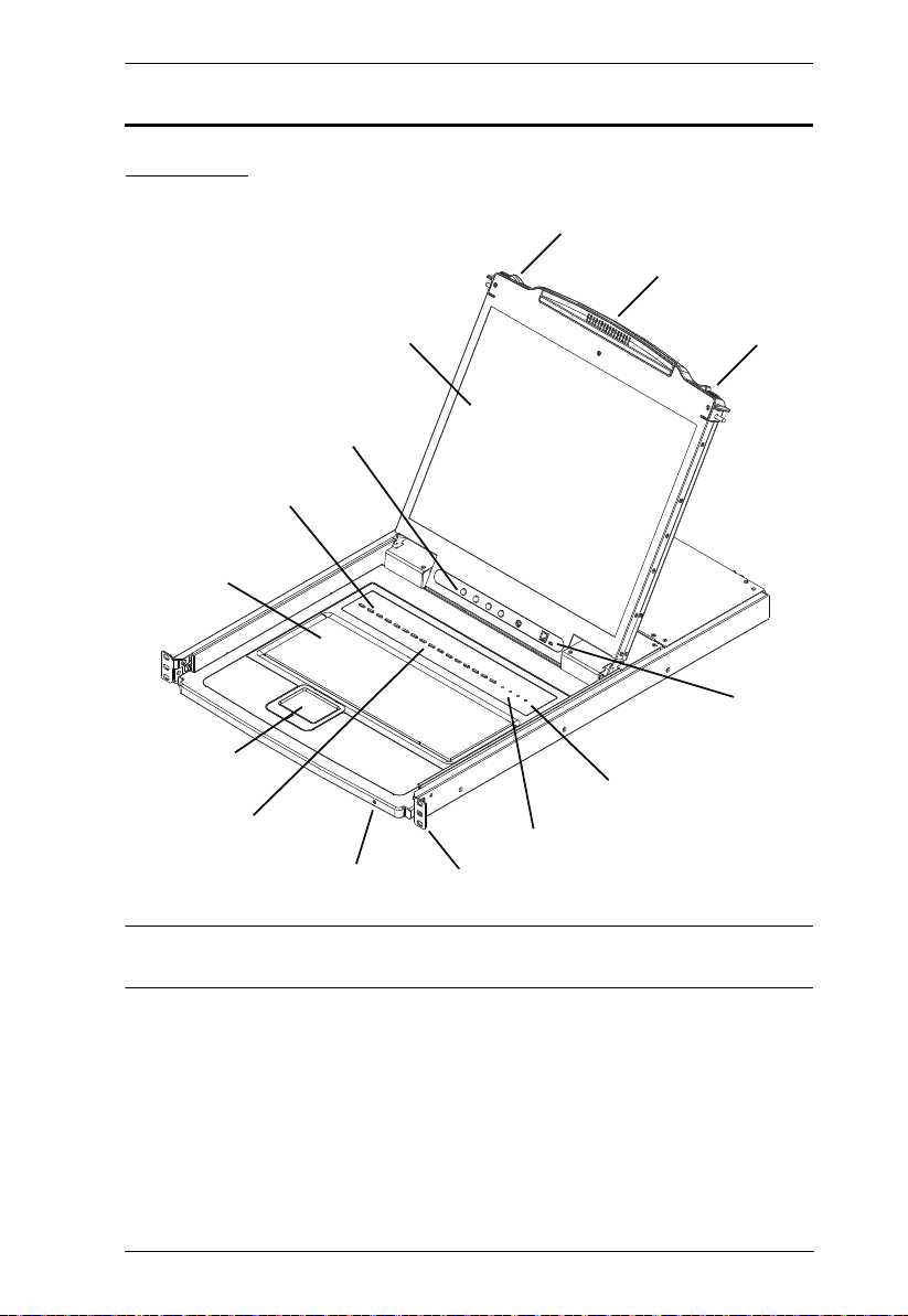
Front View
Chapter 1. Introduction
Note: The CL1316 is pictured in the diagrams of this chapter. However, the
CL1308 is the same as the CL1316, except that it has 8 KVM ports.
5
Page 16

CL1308 / CL1316 User Manual
No. Component Description
1 Handle Pull to slide the KVM module out; push to slide the module in
2 Slide Release In order to slide the console out, you must first release it by
3 LCD Display After sliding the KVM module out, flip up the cover to access
4 LCD Controls The LCD On/Off switch is located here, as well as buttons to
5 Port LEDs An orange ON LINE LED lights to indicate that the computer
6 Keyboard Standard 105-key keyboard
7 Touchpad Standard mouse touchpad
8 Port Switches Press the port pushbuttons to bring the KVM focus to the
9 Power LED Lights to indicate that the unit is receiving power.
10 Rack Mounting
Brackets
11 Lock LEDs Num Lock, Caps Lock, Scroll Lock LEDs are located here.
12 Reset Switch Located to the right of the Lock LEDs. Press this recessed
13 Firmware
Upgrade
Section
(see item 2 in this table).
sliding these tabs to the inside. See page 17 for details on
sliding the console in and out.
the LCD monitor.
control the position and picture settings of the LCD display.
See page 21 for details.
attached to its corresponding port is up and running. A green
Selected LED lights to indicate that the computer attached to
the corresponding port is selected for KVM control.
computer attached to the corresponding port.
The rack mount brackets located at each corner of the unit
secure the chassis to a system rack.
switch in with a small object to perform a system reset.
Firmware Upgrade Port: The Firmware Upgrade Cable
that transfers the firmware upgrade data from the administrator's computer to the CL1308 / CL1316 plugs into this
RJ-11 connector.
Firmware Upgrade Switch: During normal operation this
switch should be in the NORMAL position. (See The Firm-
ware Upgrade Utility, page 45 for firmware upgrading
details.)
6
Page 17
Chapter 1. Introduction
1
2
3
4
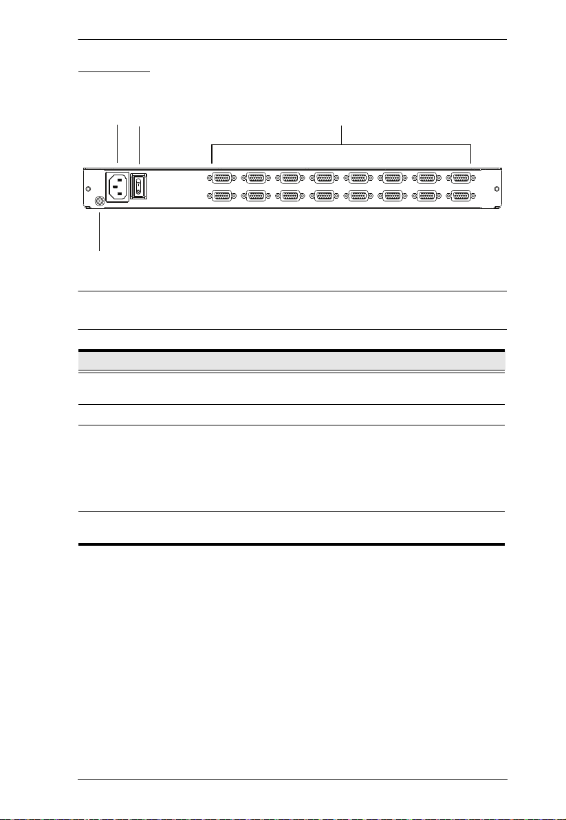
Rear View
Note: The CL1316 is pictured above. The CL1308 rear panel is the same as
the CL1316, except that it has 8 KVM ports instead of 16.
No. Component Description
1 Power Socket This is a standard 3-prong AC power socket. The power cord
2 Power Switch This standard rocker switch powers the unit on and off.
3 KVM Port
Section
4 Grounding
Terminal
from an AC source plugs in here.
The cables that link to the computers plug in here.
Note: The shape of these SPHD connectors have been
specifically modified so that only KVM cables designed to
work with this switch can plug in (see the Cables section on
page 3, for details). Do NOT attempt to use ordinary 15 pin
VGA connector cables to link these ports to the computers.
The grounding wire used to ground the switch attaches here.
7
Page 18

CL1308 / CL1316 User Manual
This Page Intentionally Left Blank
8
Page 19

Chapter 2
1. Important safety information regarding the placement of this
device is provided on page 53. Please review it before
proceeding.
2. Make sure that power to all the devices you will be connecting
up has been turned off. You must unplug the power cords of any
computers that have the Keyboard Power On function.
Hardware Setup
Overview
The CL1308 / CL1316 is a switch designed to work with USB and PS/2
interfaces. It utilizes custom KVM cables that serve as intermediaries between
the switch and computers. A custom KVM cable is required for each computer.
Custom cables of various lengths are listed on page 3. Consult your dealer to
find out which custom KVM cables best fit your needs.
Before you Begin
9
Page 20
CL1308 / CL1316 User Manual
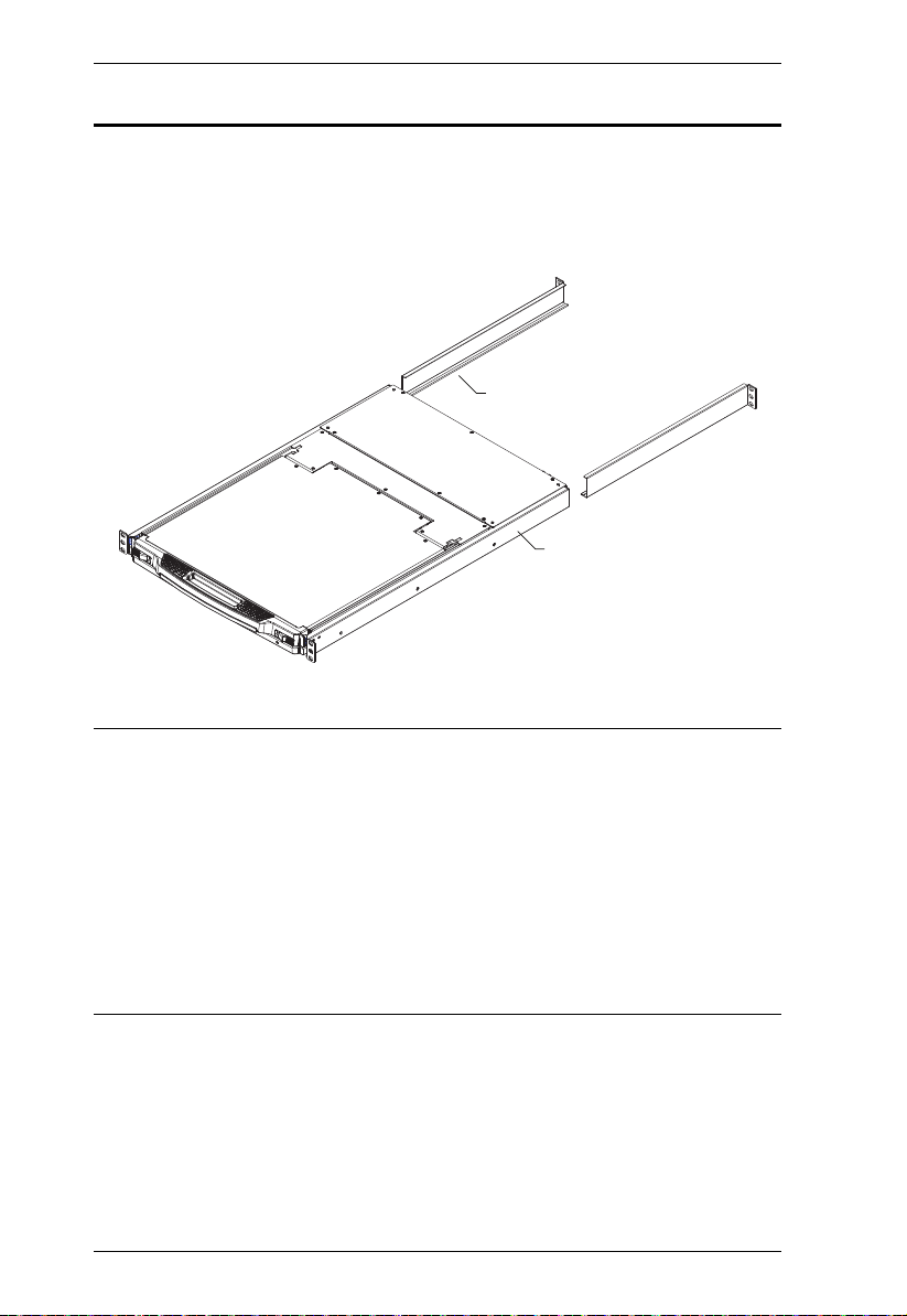
Standard Rack Mounting
A standard rack mounting kit is provided with your CL1308 / CL1316 and can
be mounted in 1U of rack space. The installation procedures are described in
the following sections. Below is an image of the parts included with your
package that will be needed for rack installation.
L Brackets
Side Mountng
Brackets
Note: 1. It takes two people to mount the switch: one to hold it in place, the
other to screw it in.
2. The standard rack mounting kit does not include screws or cage nuts.
If you need additional screws or cage nuts, contact your rack dealer.
3. Allow at least 5.1 cm on each side for proper ventilation, and at least
12.7 cm at the back for the power cord and cable clearance.
4. Optional mounting kits – including single person Easy Installation
kits – are available with a separate purchase. See Optional Rack
Mounting, page 65 for details.
10
Page 21
Chapter 2. Hardware Setup
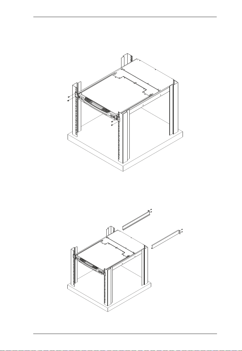
To rack mount the CL1308 / CL1316, do the following:
1. While one person positions the switch in the rack and holds it in place, the
second person loosely screws the front brackets to the rack.
2. While the first person still holds the switch in place, the second person
slides the L brackets into the switch's side mounting brackets, from the
rear until the bracket flanges contact the rack, then screws the L brackets
to the rack.
3. After the L brackets have been secured, tighten the front bracket screws.
11
Page 22
CL1308 / CL1316 User Manual
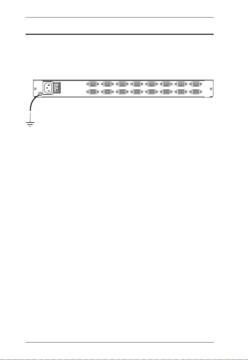
Grounding
To prevent damage to your installation it is important that all devices are
properly grounded. Use a grounding wire to ground the CL1308 / CL1316 by
connecting one end of the wire to the grounding terminal, and the other end of
the wire to a suitable grounded object.
12
Page 23
Chapter 2. Hardware Setup
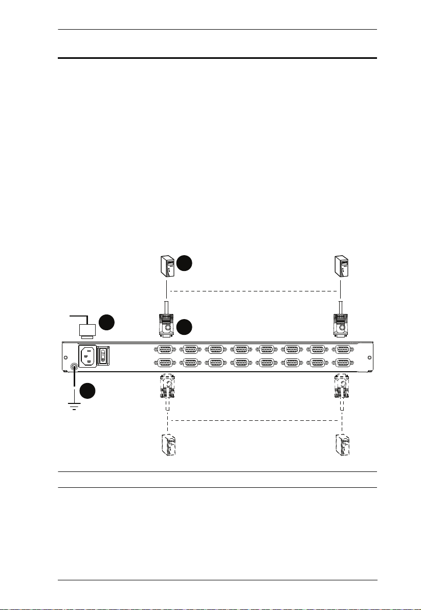
Single Level Installation
In a single level installation, there are no additional switches cascaded from the
first unit. To set up a single level installation do the following:
1. Ground the CL1308 / CL1316 and make sure that power has been turned
off to all the computers you will be connecting.
2. Use KVM cable sets* (as described in the Cables section on page 3), to
connect any available KVM port to the keyboard, video and mouse ports
of the computer you are installing. Refer to the KVM Cable Installation
Diagrams on the following page.
3. Plug the power cable into an AC power source.
4. Turn on the power to the computers.
Single Level Installation Diagram
4
3
1
2
Note: The numbers in the diagram correspond to the numbered steps above.
* Contact your KVM dealer for ordering information.
13
Page 24
CL1308 / CL1316 User Manual
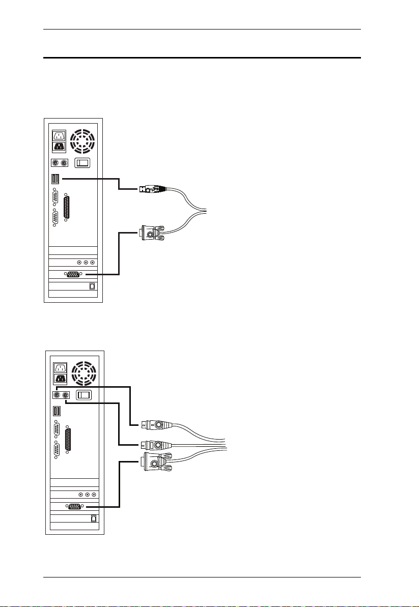
USB KVM Cable Connection
PS/2 KVM Cable Connection
Cable Connection Diagrams
KVM Cable Installation Diagrams
14
Page 25

Chapter 2. Hardware Setup
Two Level Installation
To control even more computers, up to 8/16 additional switches can be cascaded
from the first CL1308 / CL1316 (see the Appendix for a list of compatible ATEN
switches). As many as 128 (CS1308) or 256 (CS1316) computers can be
controlled from a single console in a complete cascade installation. Tables
showing the relation between the number of computers and the number of
switches needed to control them are provided on page 62 in the Appendix.
To set up a two level installation, do the following:
1. Ground the master CL1308 / CL1316 and make sure that power has been
turned off to all the computers you will be connecting up.
2. Using a KVM cable, connect any available KVM Port on the first level
switch to the Console port on the second level unit*.
3. Use KVM cable sets (described in the Cables section, page 3), to connect
any available KVM port on the CL1308 / CL1316 installation to the
keyboard, video and mouse ports of the computers you are installing.
4. Repeat the above steps for any additional units you wish to add to the
installation.
5. The Power On sequence requires that all slave units be powered on first.
After they are all on, the master unit must be powered on next. Only after
all the switches have been powered on in this sequence, can the computers
be powered on.
Note: The CL1308 / CL1316 can only be installed as the first switch in a two
level installation as its LCD, keyboard and mouse are used as the console and all
second level switches require an external console port to be cascaded.
15
Page 26

CL1308 / CL1316 User Manual
CL1316
CS1316
Two Level Installation Diagram
16
Page 27

Chapter 3
Basic Operation
Opening the Console
The CL1308 / CL1316's console is located under the top cover. To access the
console, slide the console module out and raise the cover.
Note: As a safety precaution, to keep the console from accidentally sliding
out, the console is locked into the In position. Before you can pull the
console module out, you must release it by pushing the catches on the
unit's front panel toward the center of the switch.
To slide the console module out, do the following:
1. Push the catches inward.
17
Page 28

CL1308 / CL1316 User Manual
2. Slide the module all the way out until it automatically locks in place.
3. Open the cover.
Closing the Console
To slide the console module back in, do the following:
1. Close the cover.
2. Push the module all the way in until it automatically locks in place.
18
Page 29

Operating Precautions
The maximum load bearing capacity of the keyboard module is 30kg.
Failure to heed the information below can result in damage to the
keyboard module.
Chapter 3. Basic Operation
Right!
Rest your hands and arms lightly on the
keyboard module as you work.
Wrong!
DO NOT lean your body weight on the
keyboard module.
DO NOT place heavy objects on the
keyboard module.
19
Page 30

CL1308 / CL1316 User Manual
Powering Off and Restarting
If it becomes necessary to power off the CL1308 / CL1316, do the following
before restarting it:
1. Shut down all the computers that are attached to the CL1308 / CL1316.
Note: Unplug the power cords of any computers that have the Keyboard
Power On function. Otherwise, the CL1308 / CL1316 will still
receive power from the computers.
2. Unplug the CL1308 / CL1316 from its power source.
3. Wait 10 seconds, then plug the CL1308 / CL1316 back in.
4. After the CL1308 / CL1316 has started and ascertained its station ID,
power on the computers.
Note: If you have shut down more than one station, power up the highest
station first and work your way down to the lowest one.
20
Page 31

Chapter 3. Basic Operation
LCD OSD Configuration
The LCD Buttons
The LCD OSD allows you to set up and configure the LCD display. Four
buttons are used to perform the configuration, as described in the table, below:
Button Function
MENU
EXIT
When you have not entered the LCD OSD Menu function,
pressing this button invokes the Menu function, and brings up
the Main Menu.
When you have entered the LCD OSD Menu function, and
have reached a setting choice with the navigation buttons,
pressing this button brings up its adjustment screen.
When navigating through the menus, this button moves you Right
or Up. When making an adjustment, it increases the value.
When navigating through the menus, this button moves you Left
or Down. When making an adjustment, it decreases the value.
When you have not entered the LCD OSD Menu function,
pressing this button performs an auto adjustment. An auto
adjustment automatically configures all the settings for the LCD
panel to what the OSD considers their optimum values to be.
When you have entered the LCD OSD Menu function, pressing
this button exits the current menu and returns you to the
previous menu. Use it to leave an adjustment menu when you
are satisfied with the adjustment you made.
When you are at the Main Menu, pressing this button exits the
LCD OSD.
21
Page 32

CL1308 / CL1316 User Manual
LCD Adjustment Settings
An explanation of the LCD OSD adjustment settings is given in the table below:
Setting Explanation
Brightness Adjusts the background black level of the screen image.
Contrast Adjusts the foreground white level of the screen image.
Phase If pixel jitter or horizontal line noise is visible on the display,
Clock If vertical banding is visible on the display, your LCD may
H-Position Positions the display area on the LCD panel horizontally
V-Position Positions the display area on the LCD panel vertically
Color Temperature Adjusts the color quality of the display. You can adjust the
Language Selects the language that the OSD displays its menus in.
OSD Duration Lets you set the amount of time the OSD displays on the
Reset Resets the adjustments on all menus and submenus to
your LCD may have the wrong phase setting. Adjust the
phase setting to eliminate these problems.
have the wrong clock setting. Adjust the clock setting to
eliminate vertical banding.
(moves the display area left or right).
(moves the display area up or down).
warmth value, color balance, etc. The Adjust Color
selection has a further submenu that lets you fine tune the
RGB values.
screen. If there is no input for the amount of time you
choose, the OSD display turns off.
their factory default settings.
Note: As an alternative to manually adjusting the LCD settings, you can have
the LCD auto-adjusted for optimum display by pressing the Exit button.
See EXIT, page 21
22
Page 33

Chapter 3. Basic Operation
Hot Plugging
The CL1308 / CL1316 supports hot plugging – components can be removed
and added back into the installation by unplugging their cables from the ports
without the need to shut the unit down. In order for hot plugging to work
properly, the procedures described below must be followed:
Hot Plugging KVM Ports
In order for the OSD menus to correspond to KVM port changes, you must
manually reconfigure the OSD to reflect the new port information. See the F3
SET (page 29) and F4 ADM (page 31), functions for details.
Note: If the computer's operating system does not support hot plugging, this
function may not work properly.
Port Selection
The CL1308 / CL1316 provides three port selection methods to access the
computers on the installation: Manual, OSD (on-screen display), and Hotkeys.
See Chapter 4, OSD Operation and Chapter 5, Keyboard Port Operation for
more information.
Manual Port Switching
Use the Port LED/Port Pushbuttons located on the keyboard module to switch
KVM focus to any port on the installation.
23
Page 34

CL1308 / CL1316 User Manual
Port ID Numbering
Each port on a CL1308 / CL1316 installation is assigned a unique Port ID. You
can directly access any computer on any level of the installation by specifying
the Port ID that the computer is connected to – either with the OSD (see OSD
Operation, page 25), or with the Hotkey port selection method (see Keyboard
Port Operation, page 37).
A computer attached to a master unit has a two digit Port ID (from 01–08
for the CL1308; from 01–16 for the CL1316), that corresponds to the
KVM port number that it is connected to.
A computer attached to a slave unit has a four digit Port ID.
The first two digits represent the KVM port number on the master and the
second two digits represent the KVM port number on the slave unit that
the computer is connected to. For example, a Port ID of 02–16 would refer
to a computer that is connected to KVM port 16 of a slave unit that links
back to KVM port 2 of the master unit.
24
Page 35

Chapter 4
OSD Operation
OSD Overview
The on-screen display (OSD) is a mouse and keyboard enabled, menu driven
method to handle computer control and switching operations. All procedures
start from the OSD main screen.
OSD Login
The OSD incorporates a two level (administrator / user) password system.
Before the OSD main screen displays, a login screen appears requiring a
password. If this is the first time that the OSD is used, or if the password
function has not been set, simply press [Enter]. The OSD main screen displays
in administrator mode. In this mode, you have administrator privileges, with
access to all administrator and user functions, and can set up operations
(including password authorization) as you like. If the password function has
been set, you must provide an appropriate administrator/user password in order
to access the OSD.
OSD Hotkey
You can display the OSD on the console monitor while also viewing the
display of any port on the CL1308 / CL1316 by pressing the [Scroll Lock] key
twice.
Note: You can optionally change the OSD hotkey to the Ctrl key, in which
case you would press [Ctrl] twice (see OSD Hotkey, page 29). With this
method, you must press the same [Ctrl] key.
25
Page 36

CL1308 / CL1316 User Manual
OSD Main Screen
When you invoke the OSD, a screen similar to the one below appears:
Note: 1. The diagram depicts the administrator's main screen. The user main
screen does not show the F4 and F6 functions, since these are
reserved for the administrator and can't be accessed by users.
2. The OSD always starts in list view, with the highlight bar at the same
position it was in the last time it was closed.
3. Only the ports that have been set accessible by the administrator for
the current logged in user are visible (see SET ACCESSIBLE PORTS,
page 31, for details).
4. If the port list is collapsed, click on a switch number, or move the
highlight bar to it then press the right arrow key to expand the list.
Similarly, to collapse a switch’s port list, click on the switch number,
or move the highlight bar to it then press the left arrow key to collapse
the list.
OSD Main Screen Headings
PN This column lists the port ID numbers for all the KVM ports on the
QV If a port has selected for quick view scanning (see Set Quick View Ports,
NAME If a port has been given a name (see Edit Port Names, page 32), its
26
installation. The simplest method to access a particular computer is
move the highlight bar to it, then press Enter.
page 33), an arrowhead displays in this column.
The computers that are powered on and are online have a sun symbol
in this column.
name appears in this column.
Page 37

Chapter 4. OSD Operation
OSD Navigation
To dismiss the menu, and deactivate OSD, click the X at the upper right
corner of the OSD window; or press [Esc].
To log out, click F8 at the top of the main screen, or press [F8].
To move up or down through the list one line at a time, click the up and
down triangle symbols (ST) or use the up and down arrow keys. If there
are more list entries than what can appear on the main screen, the screen
will scroll.
To move up or down through the list one screen at a time, click the up and
down arrow symbols (ÏÐ), or use the [Pg Up] and [Pg Dn] keys. If there
are more list entries than what can appear on the main screen, the screen
will scroll.
To activate a port, double-click it, or move the highlight bar to it then press
[Enter].
After executing any action, you automatically go back to the menu one
level above.
OSD Functions
OSD functions are used to configure and control the OSD. For example, you
can rapidly switch to any port, scan selected ports, limit the list you wish to
view, designate a port as a quick view port, create or edit a port name, or make
OSD setting adjustments.
To access an OSD function:
1. Either click a function key field at the top of the main screen, or press a
function key on the keyboard.
2. In the submenus that appear make your choice either by double-clicking it,
or moving the highlight bar to it, then pressing [Enter].
3. Press [Esc] to return to the previous menu level.
27
Page 38

CL1308 / CL1316 User Manual
F1: GOTO
Clicking the F1 field or pressing [F1] activates the GOTO function. GOTO
allows you to switch directly to a port either by keying in the port's Name, or
its Port ID.
To use the name method, key in 1; key in the port's Name; then press
[Enter].
To use the port ID method, key in 2; key in the Port ID; then press
[Enter].
Note: You can key in a partial name or port ID. In that case, the screen will
show all the computers that the user has Vie w rights to (see SET
ACCESSIBLE PORTS, page 31), that match the name or port ID
pattern, regardless of the current list settings (see F2 LIST, page 28, for
details).
To return to the OSD main screen without making a choice, press [Esc].
F2: LIST
This function lets you broaden or narrow the scope of which ports the OSD
displays on the main screen. The submenu choices and their meanings are
given in the table below.
Choice Meaning
ALL Lists all of the ports on the installation that have been set accessible
QUICK VIEW Lists only the ports that have been selected as quick view ports (see
POWERED ON Lists only the ports that have their attached computers powered on.
QUICK VIEW +
POWERED ON
by the administrator for the current logged in user.
SET QUICK VIEW PORTS, page 33).
Lists only the ports that have been selected as quick view ports (see
SET QUICK VIEW PORTS, page 33), and that have their attached
computers powered on.
Move the highlight bar to the choice you want, then press [Enter]. An icon
appears before the choice to indicate that it is the currently selected one.
28
Page 39

Chapter 4. OSD Operation
F3: SET
This function allows the administrator and each user to set up his own working
environment. A separate profile for each is stored by the OSD and is activated
according to the username that was provided during login.
To change a setting:
1. Double-click it; or move the highlight bar to it, then press [Enter].
2. After you select an item, a submenu with further choices appears. To make
a selection, either double-click it; or move the highlight bar to it, then
press [Enter]. An icon appears before the selected choice to indicate
which one it is. The settings are explained in the following table:
Setting Function
OSD HOTKEY Selects which hotkey activates the OSD function:
PORT ID
DISPLAY
POSITION
[Scroll Lock] [Scroll Lock] or [Ctrl] [Ctrl].
Since the [Ctrl] key combination may conflict with programs running
on the computers, the default is the [Scroll Lock] combination.
Allows each user to customize the position where the port ID
appears on the screen. The default is the upper left corner, but
users can choose to have it appear anywhere on the screen.
PORT ID
DISPLAY
DURATION
PORT ID
DISPLAY
MODE
SCAN
DURATION
Use the mouse or the arrow keys plus Pg Up, Pg Dn, Home, End,
and 5 (on the numeric keypad with Num Lock off), to position the
port ID display, then double-click or press [Enter] to lock the
position and return to the Set submenu.
Determines how long a port ID displays on the monitor after a port
change has taken place. The choices are: 3 Seconds (default) and
Always Off.
Selects how the port ID is displayed: the port number plus the port
name (PORT NUMBER + PORT NAME) (default); the port number
alone (PORT NUMBER); or the port name alone (PORT NAME).
Determines how long the focus dwells on each port as it cycles
through the selected ports in Auto Scan mode (see F7 SCAN,
page 35). Key in a value from 1–255 seconds, then press [Enter].
Default is 5 seconds; a setting of 0 disables the SCAN function.
(Continues on next page.)
29
Page 40

CL1308 / CL1316 User Manual
(Continued from previous page.)
Setting Function
SCAN–SKIP
MODE
SCREEN
BLANKER
HOTKEY
COMMAND
MODE
HOTKEY Sets the keyboard shortcut for invoking Hotkey Mode (see
OSD
LANGUAGE
Selects which computers will be accessed under skip mode (see
F5 SKP, page 34), and Auto Scan mode (see F7 SCAN, page 35.
Choices are:
ALL - All the ports which have been set accessible (see SET
ACCESSIBLE PORTS, page 31);
QUICK VIEW - Only those ports which have been set accessible
and have been selected as quick view ports (see SET QUICK
VIEW PORTS, page 33);
POWERED ON - Only those ports which have been set accessible
and are powered on;
QUICK VIEW + POWERED ON - Only those ports which have
been set accessible and have been selected as quick view ports
and are powered on. The default is ALL.
Note: The quick view choices only show up on the administrator's
screen, since only he has Quick View setting rights (see SET
QUICK VIEW PORTS, page 33, for details).
If there is no input from the console for the amount of time set with
this function, the screen is blanked. Key in a value from 1–30
minutes, then press [Enter]. The default setting of 0 disables this
function.
Enables / disables the hotkey command function in case a conflict
with programs running on the computers occurs.
page 37). Choices are: NUM LOCK + - (minus) (default), and
CTRL + F12.
Sets the language used in the OSD. Choices are: English (default),
German, Japanese, Simplified Chinese and Traditional Chinese.
30
Page 41

Chapter 4. OSD Operation
F4: ADM
F4 is an administrator only function. It allows the administrator to configure
and control the overall operation of the OSD. To change a setting double-click
it, or use the up and down arrow keys to move the highlight bar to it then press
[Enter].
After you select an item, a submenu with further choices to select from appears.
Double-click an item, or move the highlight bar to it then press [Enter]. An
icon appears before the selected item so that you know which one it is. The
settings are explained in the following table:
Setting Function
SET USER
LOGIN
SET
ACCESSIBLE
PORTS
This function is used to set usernames and passwords for the
administrator and users:
1. Usernames and passwords for one administrator and four users
can be set.
2. After you select the administrator field or one of the user fields,
a screen that allows you to key in the username and password
appears. Usernames and passwords can be from 1 to 16
characters long and can consist of any combination of letters
and numbers (A–Z, 0–9) and some additional keys (* ( ) + : - , ?
. / space).
3. For each individual, key in the username and password, confirm
the password, then press [Enter].
4. To modify or delete a previous username and/or password, use
the backspace key to erase individual letters or numbers. Press
[Enter] when done.
Note: Usernames and passwords are not case sensitive.
Usernames are displayed in capital letters in the OSD.
This function allows the administrator to define user access to the
computers on the installation on a port-by-port basis.
For each user, select the target port; then press the [Spacebar] to
cycle through the choices: F (full access), V (view only), or blank.
Repeat until all access rights have been set, then press [Enter].
The default is F for all users on all ports.
Note:
A blank setting means that no access rights are granted. The
port will not show up on the user's LIST on the main screen.
The administrator always has full access to all ports.
(Continues on next page.)
31
Page 42

CL1308 / CL1316 User Manual
(Continued from previous page.)
Setting Function
SET LOGOUT
TIMEOUT
EDIT PORT
NAMES
If there is no input from the console for the amount of time set with
this function, the user is automatically logged out. A login is
necessary before the console can be used again.
This enables other users to gain access to the computers when the
original user is no longer accessing them, but has forgotten to log
out. To set the timeout value, key in a number from 1–180 minutes,
then press [Enter]. The default setting of 0 disables this function.
Note: This feature does not function if Set Login Mode is disabled.
See SET LOGIN MODE, page 33.
To help remember which computer is attached to a particular port,
every port can be given a name. This function allows the
administrator to create, modify, or delete port names.
To edit a port name:
1. Click the port, or use the navigation keys to move the highlight
bar to it, then press [Enter].
2. Key in the new port name, or modify/delete the old one. The
maximum number of characters allowed for the port name is 12.
Legal characters include:
All alpha characters: A–Z
All numeric characters: 0–9
* ( ) + : - , ? . / and Space
Case does not matter; the OSD displays the port name in all
capitals no matter how they were keyed in.
3. When you have finished editing, press [Enter] to have the
change take effect. To abort the change, press [Esc].
RESTORE
DEFAULT
VAL UES
CLEAR THE
NAME LIST
ACTIVATE
BEEPER
This function is used to undo all changes and return the setup to
the original factory default settings (see OSD FA CTORY D EFAULT
SETTINGS, page 63) except for the port name list, username and
password information, which are saved.
This function clears the port name list.
Choices are Y (on), or N (off). When activated, the beeper sounds
whenever a port is changed; when activating the Auto Scan
function (see F7 SCAN, page 35); or an invalid entry is made on an
OSD menu. The default is Y.
32
(Continues on next page.)
Page 43

(Continued from previous page.)
Setting Function
SET QUICK
VIEW PORTS
This function lets the administrator select which ports to include as
quick view ports.
To select/deselect a port as a quick view port, double-click the
port, or use the navigation keys to move the highlight bar to it,
then press [Spacebar].
When a port has been selected as a quick view port, an icon dis-
plays in the QV column of the LIST on the main screen. When a
port is deselected, the icon disappears.
If one of the quick view options is chosen for the LIST view (see
F2 LIST, page 28), only a port that has been selected here
will display on the list.
If one of the quick view options is chosen for auto-scanning
(see SCAN/SKIP MODE, page 30), only a port that has been
selected here will be auto-scanned.
The default has no ports selected for quick view.
SET
OPERATING
SYSTEM
FIRMWARE
UPGRADE
SET KEYBOARD
LANGUAGE
SET LOGIN
MODE
This function allows the administrator to define the operating
system for the computer connected to each KVM port. The default
is WIN (PC compatible).
To set the port operating system:
1. From the list, select the port for which you wish to set the computer's operating system.
2. Set the operating system by pressing [Spacebar] to cycle
through WIN, MAC, SUN, or OTHER.
3. Press [Esc] to exit. The operating system you selected is
assigned to the KVM port.
In order to upgrade the CL1308 / CL1316 firmware (see page 45),
you must first enable Firmware Upgrade mode with this setting.
When you bring up this menu, the current firmware version levels
are displayed. Select Y to enable Firmware Upgrade mode, or N to
leave this menu without enabling it.
Sets the language for the computer keyboard attached to the KVM
port. To select a keyboard language, double-click it, or use the
navigation keys to move the highlight bar to it, then press [Enter].
Choices are: AUTO (default), ENGLISH (US), ENGLISH (UK),
GERMAN (GER.), GERMAN (SWISS), FRENCH, HUNGARIAN,
ITALIAN, JAPANESE, KOREAN, RUSSIAN, SPANISH, SWEDISH
and TRADITIONAL CHINESE.
This function allows the administrator to request users to login or
not. When the login dialog box is disabled, the system disables the
login/logout function. If the system is re-started, the login/logout
function remains disabled.
Chapter 4. OSD Operation
33
Page 44

CL1308 / CL1316 User Manual
F5: SKP
Clicking the F5 field or pressing [F5] invokes Skip (SKP) mode. This function
enables you to easily skip backward or forward – switching the console focus
from the currently active computer port to the previous or next available one.
The selection of computers to be available for skip mode switching is
made with the Scan–Skip mode setting under the F3: SET function (see
page 29).
When you are in skip mode:
press [
← ] to switch to the previous computer in the list
press [
→ ] to switch to the next computer in the list
Note: When you skip, you only skip to the previous or next available
computer that is in the Scan–Skip mode selection (page 30).
If a port has been selected for Scan–Skip mode, when the focus switches to
that port a left/right triangle symbol appears before its port ID display.
While skip mode is in effect, the console will not function normally. You
must exit skip mode in order to regain control of the console.
To exit skip mode, press [Spacebar] or [Esc].
F6: BRC
F6 is an administrator only function. Clicking the F6 field, or pressing [F6],
invokes Broadcast (BRC) mode. When this function is in effect, commands
sent from the console are broadcast to all available computers on the
installation.
This function is particularly useful for operations that need to be performed on
multiple computers, such as performing a system wide shutdown, installing or
upgrading software, etc.
While BRC mode is in effect, a speaker symbol appears before the port ID
display of the port that currently has the console focus.
While BRC mode is in effect, the mouse will not function normally. You
must exit BRC mode in order to regain control of the mouse.
To exit BRC mode, invoke the OSD (with the OSD hotkey), then click the
F6 field, or press [F6], to turn BRC mode off.
34
Page 45

Chapter 4. OSD Operation
F7: SCAN
Clicking the F7 field or pressing [F7] invokes Auto Scan mode. This function
allows you to automatically switch among the available computers at regular
intervals so that you can monitor their activity without having to take the
trouble of switching yourself.
The selection of computers to be included for auto-scanning is made with
the Scan–Skip mode setting under the F3: SET function (see page 30).
The amount of time that each port displays for is set with the Scan
Duration setting under the F3: SET function (see page 29). When you
want to stop at a particular location, press the [Spacebar] to stop scanning.
If the scanning stops on an empty port, or one where the computer is
attached but is powered Off, the monitor screen will be blank, and the
mouse and keyboard will have no effect. After the Scan Duration time is
up, the scan function will move on to the next port.
As each computer is accessed, an S appears in front of the port ID display
to indicate that it is being accessed under Auto Scan mode.
While Auto Scan mode is in effect, the console will not function normally.
You must exit Auto Scan mode in order to regain control of the console.
While you are in Auto Scan mode, you can pause the scanning in order to
keep the focus on a particular computer either by pressing P, or with a left-
click of the mouse. See Invoking Auto Scan, page 39, for details.
To e x i t Auto Scan mode, press the [Spacebar] or [Esc].
35
Page 46

CL1308 / CL1316 User Manual
F8: LOUT
Clicking the F8 field, or pressing [F8] logs you out of OSD control of the
computers, and blanks the console screen. This is different from simply
pressing [Esc] when you are at the main screen to deactivate the OSD. With
this function you must log in all over again to regain access to the OSD,
whereas with [Esc], all you have to do to reenter the OSD is tap the OSD
hotkey.
Note: 1. When you reenter the OSD after logging out, the screen stays blank
except for the OSD main screen. You must input your username and
password before you can continue.
2. If you reenter the OSD after logging out, and immediately use [Esc]
to deactivate the OSD without having selected a port from the OSD
menu, a null port message displays on the screen. The OSD hotkey
will bring up the main OSD screen.
36
Page 47

Chapter 5
Keyboard Port Operation
Hotkey Port Control
Hotkey port control allows you to provide KVM focus to a particular computer
directly from the keyboard. The CL1308 / CL1316 provides the following
hotkey port control features:
Selecting the Active Port
Auto Scan Mode Switching
Skip Mode Switching
Computer Keyboard / Mouse Reset
The following settings can also be controlled in Hotkey mode:
Setting the Beeper
Setting the Quick Hotkey
Setting the OSD Hotkey
Setting the Port Operating System
Restoring the OSD Default Values
Invoke Hotkey Mode
All hotkey operations begin by invoking Hotkey mode.1 There are two possible
keystroke sequences used to invoke Hotkey mode, though only one can be
operational at any given time:
Number Lock and Minus Keys
1. Hold down the Num Lock key;
2. Press and release the minus key;
3. Release the Num Lock key:
[Num Lock] + [-]
1. Make sure that the Hotkey Command Mode function is enabled and that you key in the
appropriate Hotkey. See page 30 for details.
37
Page 48

CL1308 / CL1316 User Manual
Control and F12 Keys
1. Hold down the Ctrl key;
2. Press and release the F12 key;
3. Release the Ctrl key:
[Ctrl] + [F12]
When Hotkey mode is active:
A command line appears on the monitor screen. The command line prompt
is the word Hotkey: in white text on a blue background, and displays the
subsequent hotkey information that you key in.
Ordinary keyboard and mouse functions are suspended – only hotkey
compliant keystrokes (described in the sections that follow), can be input.
Pressing [Esc] exits Hotkey mode.
Select the Active Port
Each KVM port is assigned a port ID (see Port ID Numbering, page 24). You
can directly access any computer on the installation with a hotkey combination
that specifies the port ID of the KVM port that a computer is connected to. To
access a computer using hotkeys:
1. Invoke hotkey mode with the [Num Lock] + [-] or [Ctrl] + [F12]
combination.
2. Key in the port ID.
The port ID numbers display on the command line as you key them in. If
you make a mistake, use [Backspace] to erase the wrong number.
3. Press [Enter].
After you press [Enter], the KVM focus switches to the designated
computer and you automatically exit hotkey mode.
Note: In hotkey mode, KVM focus will not switch to a port if an invalid
switch or port number is entered. The hotkey command line will
continue to display on the screen until you enter a valid switch and
port number combination, or exit hotkey mode.
38
Page 49

Chapter 5. Keyboard Port Operation
Auto Scan Mode
Auto Scan automatically switches, at regular intervals, among all the KVM
ports that have been set as accessible under Scan–Skip Mode, so that their
activity can be monitored automatically. See Scan–Skip Mode on page 29 for
more information.
Invoking Auto Scan:
To start Auto Scan, key in the following Hotkey combination:
1. Invoke hotkey mode with the [Num Lock] + [-] or [Ctrl] + [F12]
combination.
2. Press [A]. After you press A, then [Enter], you automatically exit hotkey
mode, and enter Auto Scan mode.
While you are in Auto Scan mode, you can pause the scanning in order
to keep the focus on a particular computer either by pressing P or with
a left click of the mouse. During the time that auto-scanning is paused,
the command line displays: Auto Scan: Paused.
Pausing when you want to keep the focus on a particular computer is
more convenient than exiting Auto Scan mode because when you
resume scanning, you start from where you left off. If, on the other
hand, you exited and restarted, scanning would start over from the very
first computer on the installation.
To resume Auto Scanning, press any key or left-click. Scanning
continues from where it left off.
While Auto Scan mode is in effect, ordinary keyboard and mouse
functions are suspended – only Auto Scan mode compliant keystrokes
and mouse clicks can be input. You must exit Auto Scan mode in order
to regain normal control of the console.
3. To exit Auto Scan mode press [Esc] or [Spacebar]. Auto-scanning stops
when you exit Auto Scan mode.
39
Page 50

CL1308 / CL1316 User Manual
Skip Mode
This feature allows you to switch between computers in order to monitor them
manually. You can dwell on a particular port for as long as you like – as
opposed to auto-scanning, which automatically switches after a fixed interval.
To invoke Skip mode, key in the following hotkey combination:
1. Invoke hotkey mode with the [Num Lock] + [-] or [Ctrl] + [F12]
combination.
2. Key in [Arrow]
Where [Arrow] refers to one of the arrow keys. After you press an
arrow, you automatically exit hotkey mode and enter Skip mode where
you can switch ports as follows:
← Skips to the first accessible port. (See Scan/Skip Mode, page 30,
for information regarding accessible ports.)
→ Skips to the next accessible port.
Once you are in Skip mode, you can keep on skipping by pressing the
arrow keys. You don't have to use the [Num Lock] + [-] combination
again.
While Skip mode is in effect, ordinary keyboard and mouse functions
are suspended – only Skip mode compliant keystrokes can be input.
You must exit Skip mode in order to regain normal control of the
console.
3. To exit Skip mode, press [Esc] or [Spacebar].
40
Page 51

Chapter 5. Keyboard Port Operation
Computer Keyboard / Mouse Reset
If the keyboard or mouse cease to function on the computer connected to the
currently selected port, you can perform a keyboard / mouse reset on the
computer. This function is essentially the same as unplugging and replugging
the keyboard and mouse on the target computer. To perform a computer
keyboard / mouse reset, key in the following hotkey combination:
1. Invoke hotkey mode with the [Num Lock] + [-] or [Ctrl] + [F12]
combination.
2. Press [F5].
After you press [F5] you automatically exit Hotkey mode and regain keyboard
and mouse control on the computer connected to the KVM port. If you fail to
regain keyboard / mouse control on the computer after pressing [F5], perform
a console keyboard and mouse reset. For more information see Port LEDs,
page 6.
Hotkey Beeper Control
The beeper (see Activate Beeper, page 32) can be hotkey toggled on and off.
To toggle the beeper, key in the following hotkey combination:
1. Invoke hotkey mode with the [Num Lock] + [-] or [Ctrl] + [F12]
combination.
2. Press [B].
After you press [B], the beeper toggles on or off. The command line displays
Beeper On or Beeper Off for one second; then the message disappears and you
automatically exit hotkey mode.
41
Page 52

CL1308 / CL1316 User Manual
Quick Hotkey Control
The Quick Hotkey (see HOTKEY, page 30) can be toggled between
[Num Lock] + [-], and [Ctrl] + [F12]. To toggle the Quick Hotkey:
1. Invoke hotkey mode with the [Num Lock] + [-] or [Ctrl] + [F12]
combination.
2. Press [H].
After you press [H], the command line displays HOTKEY HAS BEEN
CHANGED for one second; then the message disappears and you
automatically exit Hotkey mode.
OSD Hotkey Control
The OSD Hotkey (see OSD HOTKEY, page 29) can be toggled between [Scroll
Lock], [Scroll Lock] and [Ctrl], [Ctrl]. To toggle the OSD Hotkey, key in the
following hotkey combination:
1. Invoke hotkey mode with the [Num Lock] + [-] or [Ctrl] + [F12]
combination.
2. Press [T].
After you press [T], the command line displays HOTKEY HAS BEEN
CHANGED for one second; then the message disappears and you
automatically exit Hotkey mode.
42
Page 53

Chapter 5. Keyboard Port Operation
Port OS Control
A port’s operating system can be changed to match that of the computer
attached to the port. To change a port’s operating system, key in the following
hotkey combination:
1. Invoke hotkey mode with the [Num Lock] + [-] or [Ctrl] + [F12]
combination.
2. Key in [Function], where [Function] refers to one of the function keys in
the following table:
Key Description
F1 Sets the Port OS to Windows
F2 Sets the Port OS to Mac
F3 Sets the Port OS to Sun
After pressing a function key you automatically exit Hotkey mode.
Restore Default Values
This administrator only hotkey restores the CL1308 / CL1316 default values.
See RESTORE DEFAULT VALUES, page 32. To restore the default values,
key in the following hotkey combination:
1. Invoke hotkey mode with the [Num Lock] + [-] or [Ctrl] + [F12]
combination.
2. Press [R].
3. Press [Enter].
After you press [Enter], the command line displays RESET TO DEFAULT
SETTING for three seconds; then the message disappears and you
automatically exit Hotkey mode.
43
Page 54

CL1308 / CL1316 User Manual
Hotkey Summary Table
[Num Lock] + [-]
or
[Ctrl] + [F12]
[A] [Enter]
or
[Q] [Enter]
[B] Toggles the beeper on or off.
[Esc] or [Spacebar] Exits hotkey mode.
[F1] Set Operating System to Windows
[F2] Set Operating System to Mac
[F3] Set Operating System to Sun
[F5] Performs a keyboard / mouse reset on the
[H] Toggles the Quick Hotkey invocation keys
[R] [Enter] This administrator only hotkey restores the
[PN] [Enter] Switches access to the computer that
[T] Toggles the OSD Hotkey between [Ctrl]
[←] Invokes Skip mode and skips from the
[→] Invokes Skip mode and skips from the
Invokes Auto Scan mode.
When Auto Scan mode is in effect, [P] or
left-click pauses auto-scanning.
When auto-scanning is paused, pressing
any key or another left-click resumes autoscanning.
target computer.
between [Ctrl] + [F12] and [Num Lock] + [-].
switch’s default values. See RESTORE
DEFAULT VALUES, page 32.
corresponds to that port ID.
[Ctrl] and [Scroll Lock] [Scroll Lock].
current port to the first accessible port
previous to it.
current port to the next accessible port.
44
Page 55

Chapter 6
The Firmware Upgrade Utility
Introduction
The purpose of the Windows-based Firmware Upgrade Utility is to provide an
automated process for upgrading all CL1308 / CL1316 switches in an
installation. The program comes as part of a Firmware Upgrade Package that
is specific for each device.
As new firmware versions become available, new firmware upgrade packages
are posted on our website. Check the website regularly to find the latest
information and packages.
Downloading the Firmware Upgrade Package
To download the firmware upgrade package:
1. From a computer that is not part of your KVM installation go to our
website and choose the model name that relates to your device. A list of
available firmware upgrade packages appears.
2. Choose the firmware upgrade package that you wish to install (usually the
most recent) and download it to your computer.
45
Page 56

CL1308 / CL1316 User Manual
Preparation
To prepare for the firmware upgrade, do the following:
1. Use the Firmware Upgrade Cable provided with this unit to connect a COM
port on your computer to the Firmware Upgrade Port of your switch.
2. Shut down all the computers on the KVM installation.
3. From your KVM switch console, login to the OSD as the administrator
(see page 25) and select the F4 ADM function.
4. Scroll down to FIRMWARE UPGRADE. Press [Enter], then press [Y] to
invoke Firmware Upgrade mode (see page 33)
46
Page 57

Chapter 6. The Firmware Upgrade Utility
Starting the Upgrade
To upgrade the firmware:
1. Run the downloaded firmware upgrade package file either by double-
clicking the file icon, or by opening a command line and entering the full
path to it.
The Firmware Upgrade Utility welcome screen appears:
Note: The screens shown in this section are for reference only. The
wording and layout of the actual screens put up by the Firmware
Upgrade Utility may vary slightly from these examples.
2. Read and Agree to the License Agreement (enable the I Agree radio button).
3. Click Next to continue. The Firmware Upgrade Utility main screen
appears. The devices capable of being upgraded are listed in the Device
List panel:
47
Page 58

CL1308 / CL1316 User Manual
4. Click Next to perform the upgrade.
If you enabled Check Firmware Version, the Utility compares the device's
firmware level with that of the upgrade files. If it finds that the device's
version is higher than the upgrade version, it brings up a dialog box
informing you of the situation and gives you the option to continue or
cancel.
If you didn't enable Check Firmware Version, the Utility installs the
upgrade files without checking whether they are a higher level, or not.
As the upgrade proceeds, status messages appear in the Status Messages
panel, and the progress toward completion is shown on the Progress bar.
48
Page 59

Chapter 6. The Firmware Upgrade Utility
Upgrade Succeeded
After the upgrade has completed, a screen appears to inform you that the
procedure was successful.
Click Finish to close the Firmware Upgrade Utility.
Upgrade Failed
If the Upgrade Succeeded screen doesn't appear, it means that the upgrade
failed to complete successfully. See the next section, Firmware Upgrade
Recovery, for how to proceed.
49
Page 60

CL1308 / CL1316 User Manual
Firmware Upgrade Recovery
There are three conditions that call for firmware upgrade recovery:
When a firmware upgrade is manually aborted.
When the mainboard firmware upgrade fails.
When the I/O firmware upgrade fails.
To perform a firmware upgrade recovery, do the following:
1. Power off the switch.
2. Connect the Firmware Upgrade Cable to its Firmware Upgrade Port.
3. Slide the Firmware Upgrade Recovery Switch to the Recover position.
4. Power the switch back on and repeat the upgrade procedure.
5. After the switch has been successfully upgraded, power it off, and slide the
Firmware Upgrade Recovery Switch back to the Normal position.
6. If the switch is one of the cascaded switches, plug it back into the
installation.
7. Power the switch back on.
50
Page 61

Chapter 7
Keyboard Emulation
Mac Keyboard
The PC compatible (101/104 key) keyboard can emulate the functions of the
Mac keyboard. The emulation mappings are listed in the table below.
PC Keyboard Mac Keyboard
[Shift] Shift
[Ctrl] Ctrl
[Ctrl] [1]
[Ctrl] [2]
[Ctrl] [3]
[Ctrl] [4]
[Alt] Alt
[Print Screen] F13
[Scroll Lock] F14
=
[Enter] Return
[Backspace] Delete
[Insert] Help
[Ctrl]
F15
Note: When using key combinations, press and release the first key (Ctrl),
then press and release the activation key.
51
Page 62

CL1308 / CL1316 User Manual
-
Sun Keyboard
The PC compatible (101/104 key) keyboard can emulate the functions of the
Sun keyboard when the control key [Ctrl] is used in conjunction with other
keys. The corresponding functions are shown in the table below.
PC Keyboard Sun Keyboard
[Ctrl] [T] Stop
[Ctrl] [F2] Again
[Ctrl] [F3] Props
[Ctrl] [F4] Undo
[Ctrl] [F5] Front
[Ctrl] [F6] Copy
[Ctrl] [F7] Open
[Ctrl] [F8] Paste
[Ctrl] [F9] Find
[Ctrl] [F10] Cut
[Ctrl] [1]
[Ctrl] [2]
[Ctrl] [3]
[Ctrl] [4]
[Ctrl] [H] Help
+
Compose
Note: When using key combinations, press and release the first key (Ctrl),
then press and release the activation key.
52
Page 63

Appendix
Safety Instructions
General
This product is for indoor use only.
Read all of these instructions. Save them for future reference.
Follow all warnings and instructions marked on the device.
Do not place the device on any unstable surface (cart, stand, table, etc.). If
the device falls, serious damage will result.
Do not use the device near water.
Do not place the device near, or over, radiators or heat registers.
The device cabinet is provided with slots and openings to allow for
adequate ventilation. To ensure reliable operation, and to protect against
overheating, these openings must never be blocked or covered.
The device should never be placed on a soft surface (bed, sofa, rug, etc.) as
this will block its ventilation openings. Likewise, the device should not be
placed in a built in enclosure unless adequate ventilation has been provided.
Never spill liquid of any kind on the device.
Unplug the device from the wall outlet before cleaning. Do not use liquid
or aerosol cleaners. Use a damp cloth for cleaning.
The device should be operated from the type of power source indicated on
the marking label. If you are not sure of the type of power available,
consult your dealer or local power company.
The device is designed for IT power distribution systems with 230V
phase-to-phase voltage.
To prevent damage to your installation it is important that all devices are
properly grounded.
The device is equipped with a 3-wire grounding type plug. This is a safety
feature. If you are unable to insert the plug into the outlet, contact your
electrician to replace your obsolete outlet. Do not attempt to defeat the
purpose of the grounding-type plug. Always follow your local/national
wiring codes.
Do not allow anything to rest on the power cord or cables. Route the
power cord and cables so that they cannot be stepped on or tripped over.
53
Page 64

CL1308 / CL1316 User Manual
If an extension cord is used with this device make sure that the total of the
ampere ratings of all products used on this cord does not exceed the
extension cord ampere rating. Make sure that the total of all products
plugged into the wall outlet does not exceed 15 amperes.
To help protect your system from sudden, transient increases and
decreases in electrical power, use a surge suppressor, line conditioner, or
un-interruptible power supply (UPS).
Position system cables and power cables carefully; Be sure that nothing
rests on any cables.
Never push objects of any kind into or through cabinet slots. They may
touch dangerous voltage points or short out parts resulting in a risk of fire
or electrical shock.
Do not attempt to service the device yourself. Refer all servicing to
qualified service personnel.
If the following conditions occur, unplug the device from the wall outlet
and bring it to qualified service personnel for repair.
The power cord or plug has become damaged or frayed.
Liquid has been spilled into the device.
The device has been exposed to rain or water.
The device has been dropped, or the cabinet has been damaged.
The device exhibits a distinct change in performance, indicating a need
for service.
The device does not operate normally when the operating instructions
are followed.
Only adjust those controls that are covered in the operating instructions.
Improper adjustment of other controls may result in damage that will
require extensive work by a qualified technician to repair.
Do not connect the RJ-11 connector marked “UPGRADE” to a public
telecommunication network.
54
Page 65

Appendix
Rack Mounting
Before working on the rack, make sure that the stabilizers are secured to
the rack, extended to the floor, and that the full weight of the rack rests on
the floor. Install front and side stabilizers on a single rack or front
stabilizers for joined multiple racks before working on the rack.
Always load the rack from the bottom up, and load the heaviest item in the
rack first.
Make sure that the rack is level and stable before extending a device from
the rack.
Do not overload the AC supply branch circuit that provides power to the
rack. The total rack load should not exceed 80 percent of the branch circuit
rating.
Make sure that all equipment used on the rack – including power strips and
other electrical connectors – is properly grounded.
Ensure that proper airflow is provided to devices in the rack.
Ensure that the operating ambient temperature of the rack environment
does not exceed the maximum ambient temperature specified for the
equipment by the manufacturer
Do not step on or stand on any device when servicing other devices in a rack.
55
Page 66

CL1308 / CL1316 User Manual
Consignes de sécurité
Général
Ce produit est destiné exclusivement à une utilisation à l’intérieur.
Veuillez lire la totalité de ces instructions. Conservez-les afin de pouvoir
vous y référer ultérieurement.
Respectez l’ensemble des avertissements et instructions inscrits sur
l’appareil.
Ne placez jamais l’unité sur une surface instable (chariot, pied, table, etc.).
Si l’unité venait à tomber, elle serait gravement endommagée.
N’utilisez pas l’unité à proximité de l’eau.
Ne placez pas l’unité à proximité de ou sur des radiateurs ou bouches de
chaleur.
Le boîtier de l’unité est doté de fentes et d’ouvertures destinées à assurer
une ventilation adéquate. Pour garantir un fonctionnement fiable et
protéger l’unité contre les surchauffes, ces ouvertures ne doivent jamais
être bloquées ou couvertes.
L’unité ne doit jamais être placée sur une surface molle (lit, canapé, tapis,
etc.) car ses ouvertures de ventilation se trouveraient bloquées. De même,
l’unité ne doit pas être placée dans un meuble fermé à moins qu'une
ventilation adaptée ne soit assurée.
Ne renversez jamais de liquides de quelque sorte que ce soit sur l’unité.
Débranchez l’unité de la prise murale avant de la nettoyer. N’utilisez pas
de produits de nettoyage liquide ou sous forme d’aérosol. Utilisez un
chiffon humide pour le nettoyage de l’unité.
L’appareil doit être alimenté par le type de source indiqué sur l’étiquette.
Si vous n’êtes pas sûr du type d’alimentation disponible, consultez votre
revendeur ou le fournisseur local d’électricité.
Afin de ne pas endommager votre installation, vérifiez que tous les
périphériques sont correctement mis à la terre.
L’unité est équipée d’une fiche de terre à trois fils. Il s’agit d’une fonction
de sécurité. Si vous ne parvenez pas à insérer la fiche dans la prise murale,
contactez votre électricité afin qu’il remplace cette dernière qui doit être
obsolète. N’essayez pas d’aller à l’encontre de l’objectif de la fiche de
terre. Respectez toujours les codes de câblage en vigueur dans votre
région/pays.
56
Page 67

Appendix
L’équipement doit être installé à proximité de la prise murale et le
dispositif de déconnexion (prise de courant femelle) doit être facile
d’accès.
La prise murale doit être installée à proximité de l’équipement et doit être
facile d’accès.
Veillez à ce que rien ne repose sur le cordon d’alimentation ou les câbles.
Acheminez le cordon d’alimentation et les câbles de sorte que personne ne
puisse marcher ou trébucher dessus.
En cas d’utilisation d’une rallonge avec cette unité, assurez-vous que le
total des ampérages de tous les produits utilisés sur cette rallonge ne
dépasse pas l’ampérage nominal de cette dernière. Assurez-vous que le
total des ampérages de tous les produits branchés sur la prise murale ne
dépasse pas 15 ampères.
Pour contribuer à protéger votre système contre les augmentations et
diminutions soudaines et transitoires de puissance électrique, utilisez un
parasurtenseur, un filtre de ligne ou un système d’alimentation sans
coupure (UPS).
Placez les câbles du système et les câbles d’alimentation avec précaution ;
veillez à ce que rien ne repose sur aucun des câbles.
Lors du branchement ou du débranchement à des blocs d’alimentation
permettant la connexion à chaud, veuillez respecter les lignes directrices
suivantes:
Installez le bloc d’alimentation avant de brancher le câble d’alimentation à
celui-ci.
Débranchez le câble d’alimentation avant de retirer le bloc d'alimentation.
Si le système présente plusieurs sources d’alimentation, déconnectez le
système de l'alimentation en débranchant tous les câbles d'alimentation des
blocs d'alimentation.
N’insérez jamais d’objets de quelque sorte que ce soit dans ou à travers les
fentes du boîtier. Ils pourraient entrer en contact avec des points de tension
dangereuse ou court-circuiter des pièces, entraînant ainsi un risque
d’incendie ou de choc électrique.
N’essayez pas de réparer l’unité vous-même. Confiez toute opération de
réparation à du personnel qualifié.
Si les conditions suivantes se produisent, débranchez l’unité de la prise
murale et amenez-la à un technicien qualifié pour la faire réparer:
Le cordon d’alimentation ou la fiche ont été endommagés ou éraillés.
Du liquide a été renversé dans l’unité.
57
Page 68

CL1308 / CL1316 User Manual
L’unité a été exposée à la pluie ou à l’eau.
L’unité est tombée ou le boîtier a été endommagé.
Les performances de l’unité sont visiblement altérées, ce qui indique la
nécessité d’une réparation.
L’unité ne fonctionne pas normalement bien que les instructions
d’utilisation soient respectées.
N’utilisez que les commandes qui sont abordées dans le mode d’emploi.
Le réglage incorrect d’autres commandes peut être à l’origine de
dommages qui nécessiteront beaucoup de travail pour qu’un technicien
qualifié puisse réparer l’unité.
Ne connectez pas le connecteur RJ-11 portant la marque « Sensor »
(Capteur) à un réseau de télécommunication public.
Montage sur bâti
Avant de travailler sur le bâti, assurez-vous que les stabilisateurs sont bien
fixées sur le bâti, qu’ils sont étendus au sol et que tout le poids du bâti
repose sur le sol. Installez les stabilisateurs avant et latéraux sur un même
bâti ou bien les stabilisateurs avant si plusieurs bâtis sont réunis, avant de
travailler sur le bâti.
Chargez toujours le bâti de bas en haut et chargez l’élément le plus lourd
en premier.
Assurez-vous que le bâti est à niveau et qu’il est stable avant de sortir une
unité du bâti.
Agissez avec précaution lorsque vous appuyez sur les loquets de libération
du rail d’unité et lorsque vous faites coulisser une unité dans et hors d’un
bâti ; vous pourriez vous pincer les doigts dans les rails.
Une fois qu’une unité a été insérée dans le bâti, étendez avec précaution le
rail dans une position de verrouillage puis faites glisser l’unité dans le bâti.
Ne surchargez pas le circuit de l’alimentation CA qui alimente le bâti. La
charge totale du bâti ne doit pas dépasser 80 % de la capacité du circuit.
Assurez-vous que tous les équipements utilisés sur le bâti, y-compris les
multiprises et autres connecteurs électriques, sont correctement mis à la
terre.
Assurez-vous que les unités présentes dans le bâti bénéficie d’une
circulation d’air suffisante.
58
Page 69

Appendix
Assurez-vous que la température ambiante de fonctionnement de
l’environnement du bâti ne dépasse pas la température ambiante maximale
spécifiée pour l’équipement par le fabricant.
Ne marchez sur aucun appareil lors de la maintenance d’autres appareils
d’un bâti.
59
Page 70

CL1308 / CL1316 User Manual
Technical Support
International
For online technical support – including troubleshooting, documentation,
and software updates: http://support.aten.com
For telephone support, see Telephone Support, page iii:
North America
Email Support support@aten-usa.com
Online
Technical
Support
Telephone Support 1-888-999-ATEN ext 4988
When you contact us, please have the following information ready beforehand:
Product model number, serial number, and date of purchase.
Your computer configuration, including operating system, revision level,
expansion cards, and software.
Any error messages displayed at the time the error occurred.
The sequence of operations that led up to the error.
Any other information you feel may be of help.
Troubleshooting
Documentation
Software Updates
http://www.aten-usa.com/support
60
Page 71

Specifications
Function CL1308 CL1316
Computer
Connections
Port Selection OSD, Hotkey, Pushbutton
Connectors KVM Ports 8 x SPHD-17 Female
Switches Rest 1 x Semi-recessed Pushbutton
LEDs On Line 8 (Orange) 16 (Orange)
Emulation Keyboard / Mouse PS/2, USB
Video 1280 x 1024; DDC2B
Scan Interval 1–255 Seconds
Power Consumption 22W 22.9W
Environment Operating Temp. 0–50ºC
Physical
Properties
Direct 8 16
Max. 128 (via cascade) 256 (via cascade)
(Yellow)
F/W Upgrade 1 x RJ11 Female (Black)
Power 1 x 3-prong AC Socket (IEC60320/C14)
Power 1 x Rocker Switch
Firmware Upgrade 1 x Slide Switch
LCD Control 4 x Pushbutton
LCD On/Off 1 x Pushbutton
Port Selection 8 x Pushbutton 16 x Pushbutton
Selected 8 (Green) 16 (Green)
Power KVM 1 (Dark Green)
LCD 1 (Orange)
Lock Num 1 (Green)
Caps 1 (Green)
Scroll 1 (Green)
Storage Temp -20–60ºC
Humidity 0–80% RH, Noncondensing
Housing Metal + Plastic
Weight 12.42 kg 12.58 kg
Dimensions
(L x W x H)
68.9 x 48.30 x 4.4 cm
16 x SPHD-17 Female
(Yellow)
Appendix
61
Page 72

CL1308 / CL1316 User Manual
Connection Tables
The following tables indicate the relationship between the number of switches
and the maximum number of computers that they can control.
CL1308 to Compatible 8-Port Switches
Switches Computers Switches Computers Switches Computers
1 8 429750
215536857
322643964
CL1308 to Compatible 16-Port Switches
Switches Computers Switches Computers Switches Computers
1 8 453798
2235688113
3386839128
CL1316 to Compatible 8-Port Switches
Switches Computers Switches Computers Switches Computers
11675813100
22386514107
33097215114
4 37107916121
5 44118617128
6 511293 – –
CL1316 to Compatible 16-Port Switches
Switches Computers Switches Computers Switches Computers
1 16 7 106 13 196
2 31 8 121 14 211
3 46 9 136 15 226
4 61 10 151 16 241
5 76 11 166 17 256
6 91 12 181 – –
62
Page 73

Appendix
Supported KVM Switches
The table below lists KVM switches that are compatible with the CL1308 /
CL1316 and the type of expansion that they use. (KVM switches listed below
are sold separately. Contact your dealer for details.)
Expansion Type Brand Model Name
Cascade ATEN CS1308 8 Port USB / PS/2 KVM Switch
CS1316 16 Port USB / PS/2 KVM Switch
63
Page 74

CL1308 / CL1316 User Manual
OSD Factory Default Settings
The factory default settings are as follows:
Setting Default
OSD Hotkey [Scroll Lock] [Scroll Lock]
Port ID Display Position Upper Left Corner
Port ID Display Duration 3 Seconds
Port ID Display Mode Port Number plus Port Name
Scan Duration 5 Seconds
Scan-Skip Mode All
Screen Blanker 0 (Disabled)
Logout Timeout 0 (Disabled)
Beeper Y (Activated)
Accessible Ports F (Full) For all Users on all Ports
64
Page 75

Appendix
Optional Rack Mounting
For convenience and flexibility, three optional rack mounting kits are available:
A long bracket standard rack mounting kit for 70.0–105.0 cm racks;
A short bracket Easy-Installation rack mount kit for 57.0–70.0 cm racks;
A long bracket Easy-Installation rack mount kit for 68.0–105.0 cm racks.
Standard - Long
To install the long bracket standard rack mount kit, simply replace the short L
brackets on the standard rack mount kit with the long ones, and mount the
switch according to the instructions given for Standard Rack Mounting,
page 10.
Easy Installation
With an Easy-Installation, kit, one person can mount the switch. To install the
Easy-Installation kit, do the following:
1. Remove the standard L brackets, and the side mounting brackets from both
sides of the switch.
65
Page 76

CL1308 / CL1316 User Manual
Front Flang
Slide bar
Rear Flang
Rear Attachment
Support Flang
Sliding Bracket
Left Rail
Right Rail
2. Attach the left and right easy-installation mounting rails to the inside of
the rack. The flange that supports the switch will be to the inside.
a) Screw the front flanges to the rack first.
b) Slide the bars with the rear flanges toward the rack until the flanges
make contact with the rack, then screw the rear flanges to the rack.
66
(Continues on next page.)
Page 77

Appendix
Phillips I Head
M4L6
Phillips I Head
M4L6
Phillips I Head
M4L6
(Continued from previous page.)
3. Slide the switch onto the support flanges. Use the screws supplied with
this package to loosely attach the front of the switch to the front of the rack
(only tighten the screws part way).
4. Slide the rear attachment sliding brackets along the slide bars until they
contact the rear of the switch, then use the screws supplied with this
package to attach the bars to the rear of the switch (tighten the screws all
the way).
67
Page 78

CL1308 / CL1316 User Manual
5. Slide the switch open and closed a couple of times to be sure that it is
properly aligned and operating smoothly. (See p. 17 for opening and
closing procedures.)
6. After determining that the switch is properly lined up and operating
correctly, finish up by fully tightening down the partially tightened front
attachment screws inserted in step 3.
About SPHD Connectors
This product uses SPHD connectors for its KVM and/or
Console ports. We have specifically modified the shape of these
connectors so that only KVM cables that we have designed to
work with this product can be connected.
68
Page 79

Appendix
Limited Warranty
IN NO EVENT SHALL THE DIRECT VENDOR'S LIABILITY EXCEED THE PRICE PAID
FOR THE PRODUCT FROM DIRECT, INDIRECT, SPECIAL, INCIDENTAL, OR
CONSEQUENTIAL DAMAGES RESULTING FROM THE USE OF THE PRODUCT, DISK,
OR ITS DOCUMENTATION.
The direct vendor makes no warranty or representation, expressed, implied, or statutory with
respect to the contents or use of this documentation, and especially disclaims its quality,
performance, merchantability, or fitness for any particular purpose.
The direct vendor also reserves the right to revise or update the device or
documentation without obligation to notify any individual or entity of such
revisions, or update. For further inquiries, please contact your direct vendor.
Troubleshooting
Operation problems can be due to a variety of causes. The first step in solving
them is to make sure that all cables are securely attached and seated completely
in their sockets.
In addition, updating the product’s firmware may solve problems that have
been discovered and resolved since the prior version was released. If your
product is not running the latest firmware version, we strongly recommend that
you upgrade. See The Firmware Upgrade Utility, page 45, for upgrade details.
Symptom Possible Cause Action
Erratic behavior. Unit not receiving
enough power.
Check that the power adapter that was
supplied with the unit is plugged in
and functioning properly.
69
Page 80

CL1308 / CL1316 User Manual
This Page Intentionally Left Blank
70
 Loading...