

Atek RCS 2100 User Manual
1
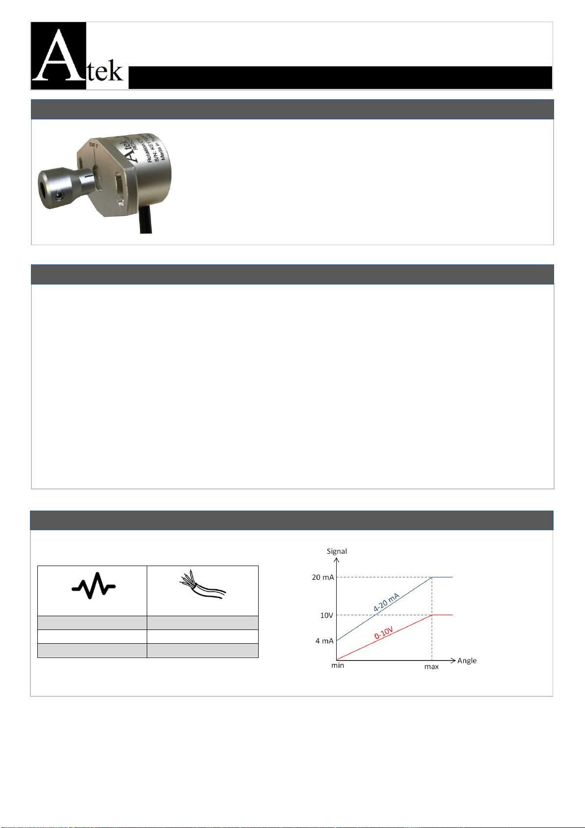
SIGNAL
CABLE COLOR
+V
Red
0V
Black
Output Signal
Yellow
The installation of the product is carried out by the customer who purchases the product, according to the wiring diagrams,
installation information, etc. in this manual.
Maintenance and repair should be done by the technicians authorized by the manufacturer firm.
There must be minimum distance between the sensor and control unit. Avoid additions except the suitable connector unless
it needs.
Keep away the sensor cable from as high power energy cables, contactor, motor, switched power supplies, inductive and
capacitive noisy supplies.
Not to damage the sensor, supply directions and voltage must be paid attention. Don’t energize before all connections
completed.
Transport and storage should be at their original packaging and an ambient temperature of -25°C / +85°C in such a way that
they will not be exposed to dust, humudity, impact, vibration, falling or water.
Chemicals such as alcohol, thinner etc. should not be used for cleaning the product. The product should be wiped with a
damp cloth.
The product may be damaged and may become unusable if used outside of the specifications in the user manual. In this case,
the product will be out of warranty.
RCS 2100
ANGLE SENSOR USER MANUAL
WARNINGS
GENERAL INFORMATIONS
ELECTRICAL CONNECTION
The RCS 2100 series sensors are used for taking angle measurement between The
measuring limits can be adjusted between 0-360 ° depending on the user request. They
have 0-10 V, 4-20 mA or ratiometric outpput options.
RCS 2100 angle sensors with high accuracy, compact design and robust construction; offers
suitable solutions for angle measurement in industrial areas like crane and lifting systems,
robotic systems, solar energy, wind power plants, auto parts etc. Thanks to their high IP
protection class, they can work in harsh environmental conditions.
KK-RCS.002 20.03.19 Rev No:0
2
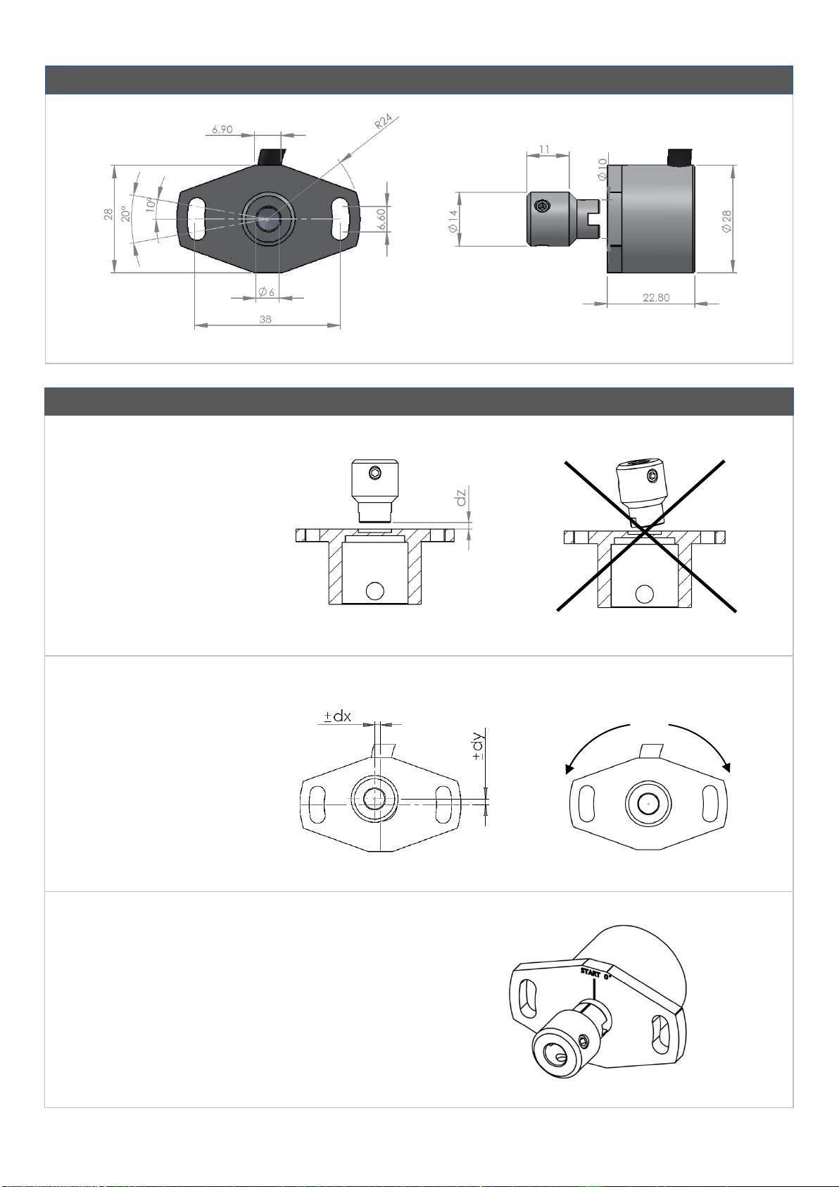
DIMENSIONS (mm)
MEKANİK MONTAJ
MOUNTING INFORMATIONS
Working Position
dz: 0,8 mm max.
Max. misalignment value of
magnet
dx: ±0,25 mm max.
dy: ±0,25 mm max.
Counter
Clockwise
(CCW)
Clockwise
(CW)
0° Point
The point where the guiding lines on the body and
the magnet intersect is the 0 ° point.
KK-RCS.002 20.03.19 Rev No:0
 Loading...