

Atek AWP 120, AWP-120-500-5K-S13-A, AWP 120-***-**-*-A, AWP 120-***-**-*-V User Manual
1
AWP 120
DRAW WIRE SENSOR USER MANUAL
AWP 120 series draw wire sensors; consists of a rotary potentiometer which is controled by
Different measuring lengths from 400 mm to 3000 mm are available. They converts linear
The “V” series, works with 24VDC supply and gives of 0-10 VDC analog output with the help of
requested.
Never make or undo electrical connections to the sensor when voltage is applied, otherwise this may result in damage to
devices.
The installation of the product is carried out by the customer who purchases the product, according to the wiring diagrams,
Transport and storage should be at their original packaging and an ambient temperature of -25°C / + 85°C in such a way that they
than authorized services.
* Output Signal may be potentiometric, 0-10 VDC or 4-20 mA depending on the
WARNINGS
GENERAL INFORMATION
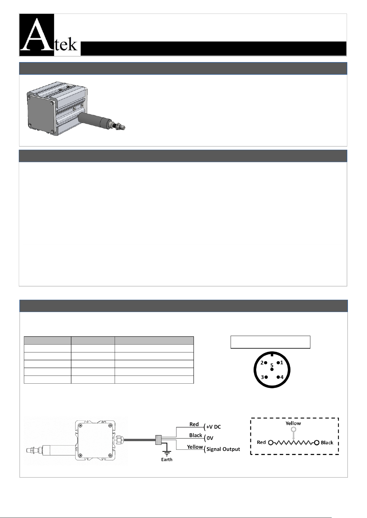
ELECTRICAL CONNECTIONS
SIGNAL
CABLE COLOR
M12 5 PIN MALE SOCKET
Earth
Silver (mesh)
Pin 1
+V
Red
Pin 2
0V
Black
Pin 3
Output Signal*
Yellow
Pin 4
- - Pin 5
M12 5 Pin Male Socket
stainless steel wire. They make measurement by pulling and rewinding stainless steel wire.
motion to potentiometric output.
The “A” series, works with 24VDC supply and gives of 4-20 mA analog output with the help of
the converter card.
the converter card.
Optionally, different non-standard measuring lengths, cable length or socket model can be
installation information, etc. in this manual.
Maintenance and repair should be done by the technicians authorized by the manufacturer firm.
There must be minimum distance between the sensor and control unit. Avoid additions except the suitable connector unless it
needs.
Keep away the sensor cable from as high power energy cables, contactor, motor, switched power supplies, inductive and capacitive
noisy supplies.
Shielding edge of the sensor cable must be ground connected.
Not to damage the sensor, supply directions and voltage must be paid attention. Don’t energize before all connections completed.
will not be exposed to dust, humudity, impact, vibration, falling or water.
Chemicals such as alcohol, thinner etc. should not be used for cleaning the product. The product should be wiped with a damp
cloth.
The product may be damaged and may become unusable if used outside of the specifications in the user manual.
The product will be out of warranty if used outside of the specifications in the user manual and opened or repaired other
model (See Product code table).
KK-AWP.004 28.09.18 Rev No:0
2
*Stroke (measuring)
length
Different measuring lengths from 400
mm to 3000 mm
Required Force
5 N
Linearity
±0.25% FS
Operating
Temperature
-25°C … +85°C
*Supply Voltage
‘A‘ and ‘V’ models: 24 VDC
Potentiometric output model: 42V max.
Relative Humidity
%95
*Signal Output Type
Potentiometric
0-10 VDC
4-20 mA
Materials
Housing: Aluminum/steel /ABS
plastic
Measuring Wire: Stainless steel
(0.5mm or 1mm)
Measuring Type
Potentiometric
*Connection cable
length
3m (standard), 5m, 10m
*Resistance
5 KΩ (standard), 10 KΩ
IP Protection Class
IP65
Maximum Speed
2 m/s
Weight
≈550 gr
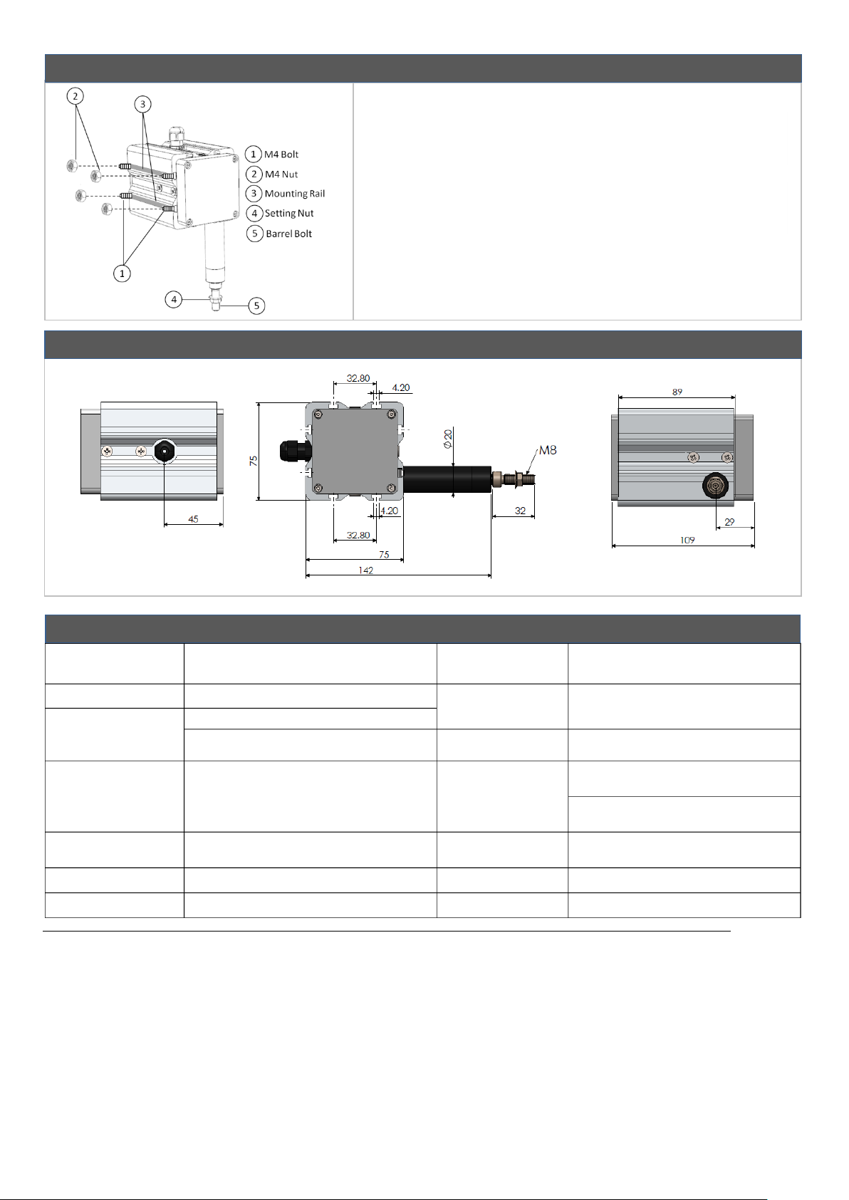
MECHANICAL MOUNTING
1- The product should be mounted to the relevant area with 2 units
3- The sensor wire should be mounted on the device to be connected
DIMENSIONS
TECHNICAL SPECIFICATIONS
M4 bolts(1) and nuts(2) from the mounting rails (3) according to the
mounting directions shown on page 3.
2- The sensor wire should be pulled towards the position to be
connected with the barrel bolt (5).
by using the setting nut (4).
Note: The technical specifications indicated by (*) vary according to the selected model. The detailed code table is shown on page 4.
KK-AWP.004 28.09.18 Rev No:0
 Loading...