

Atek ADR 10 Operation Manual
OPERATION
MANUAL
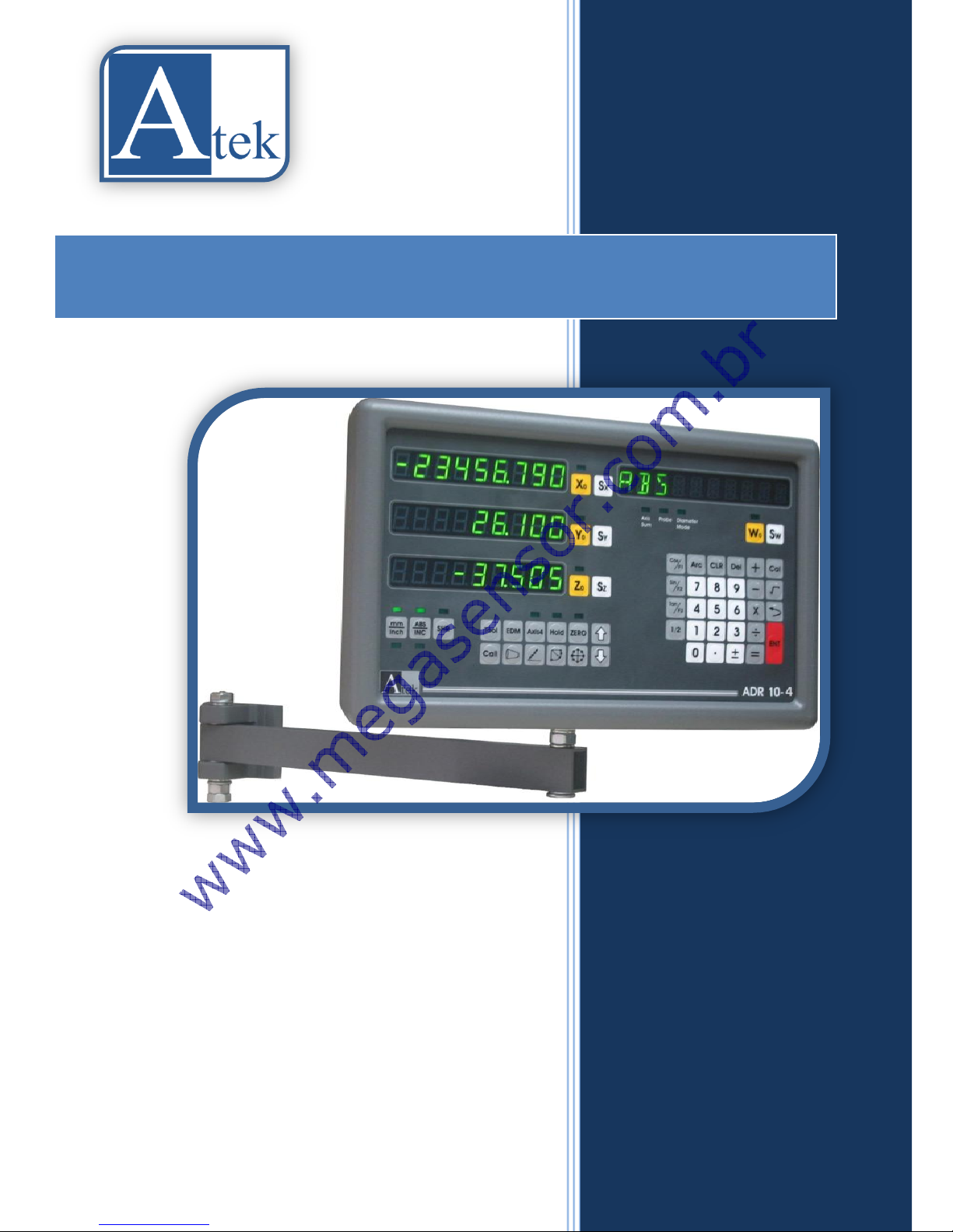
Atek ADR 10 Series
HIGH PERFORMANCE
DIGITAL READOUT

[1]
Ingredients
1. ATEK DIGITAL READOUT SYSTEMS........................................................................................................................... 3
1.1. ATEK linear encoder and digital coordinate readout unite usage advantages ................................................. 3
1.2. ATEK Magnetic Linear Encoder ......................................................................................................................... 3
2. TECHNICAL PARAMETERS......................................................................................................................................... 4
3. SYSTEM SETUP .......................................................................................................................................................... 8
3.1. Language Selection ........................................................................................................................................... 8
3.2. Resolution Setup ............................................................................................................................................... 8
3.3. Direction Setup ................................................................................................................................................. 9
3.4. Machine Tool Selection ..................................................................................................................................... 9
3.5. Compansation Selection ................................................................................................................................... 9
3.6. Advanced Settings ............................................................................................................................................. 9
3.6.1. Digit On-Off ............................................................................................................................................. 10
3.6.2. Axis Addition ........................................................................................................................................... 10
3.6.3. 4. Axis Type ............................................................................................................................................. 10
3.6.4. Calculator Decimal Setup ........................................................................................................................ 10
3.6.5. Probe Logic Level Setup .......................................................................................................................... 11
3.6.6. Buzzer Close ............................................................................................................................................ 11
3.6.7. Return to Factory Settings ...................................................................................................................... 11
3.7. Test .................................................................................................................................................................. 11
3.7.1. Display Test ............................................................................................................................................. 11
3.7.2. Eeprom Test ............................................................................................................................................ 12
3.7.3. Keyboard Test ......................................................................................................................................... 12
3.7.4. CPU Test .................................................................................................................................................. 12
3.7.5. Relay Test ................................................................................................................................................ 12
4. Basic Functions ....................................................................................................................................................... 13
4.1. Measurement System Change ........................................................................................................................ 13
4.2. Operation Mode Selection .............................................................................................................................. 13
4.3. Quick Zero Axis Values .................................................................................................................................... 13
4.4. Manuel Value Setting for Each Axis: ............................................................................................................... 13
4.5. Setting Half Value of The Display Value (Milling, Bohrwerk) .......................................................................... 14
4.6. Diameter Mode (Lathe):.................................................................................................................................. 14
4.7. Center Find (Milling, Bohrwerk) ...................................................................................................................... 14
4.8. Simple Calculation on Axis Values:.................................................................................................................. 16
4.9. Undo Function ................................................................................................................................................. 16
4.10. Activate the 4th Axis ................................................................................................................................... 16
4.11. Display Angle on the 4th Axis ...................................................................................................................... 17

[2]
4.12. Sleep Mode: ................................................................................................................................................ 17
5. ADVANCED FUNCTIONS ......................................................................................................................................... 18
5.1. To Find Zero Point of the Machine Tool.......................................................................................................... 18
5.1.1. Ruler Zero Point: ..................................................................................................................................... 18
5.1.2. Mechanical Zero Point: ........................................................................................................................... 19
5.2. Error Compensation Function: ........................................................................................................................ 20
5.2.1. Linear Error Compensation Function: ..................................................................................................... 20
5.2.2. Segmented Error Compansation Function: ............................................................................................. 21
5.3. Travel Limit: ..................................................................................................................................................... 23
5.4. Axis Addition (Lathe, Bohrwerk) ..................................................................................................................... 24
5.5. Shrink Function: .............................................................................................................................................. 25
5.6. Calculator Function: ........................................................................................................................................ 26
5.6.1. To Transfer the Calculated Values To The Axes: ..................................................................................... 26
5.6.2. To Transfer The Axis Values To Calculator: ............................................................................................. 27
5.7. Datum Point Memory: .................................................................................................................................... 28
5.8. Bolt Hole Circle (Divisor) (Milling) ................................................................................................................... 32
5.9. Bolt Hole Line Function (Milling) ..................................................................................................................... 34
5.10. Smooth Radius (Milling) .............................................................................................................................. 36
5.11. Simple Radius (Milling) ................................................................................................................................ 39
5.12. Linear Hole Patterns (Milling) ..................................................................................................................... 41
5.13. Frame Hole Patterns (Milling) ..................................................................................................................... 43
5.14. Rectangular Pocket (Milling) ....................................................................................................................... 45
5.15. Work Piece Angle Measuring (Milling) ........................................................................................................ 47
5.16. Touch Probe (Milling, Bohrwerk) ................................................................................................................ 48
5.16.1. Zero the Axis / Setting Half Value of the Display Value .......................................................................... 48
5.16.2. Find Center .............................................................................................................................................. 49
5.16.3. Measurement .......................................................................................................................................... 50
5.17. Tool Diameter Compansation (Milling) ....................................................................................................... 52
5.18. Tool Storeroom (Lathe) .............................................................................................................................. 53
5.19. Taper Angle Measurement (Lathe) ............................................................................................................. 56
5.20. Digital Filter (Vibration Filter) ..................................................................................................................... 57
5.21. Inclined Z Axis Machining (Milling) ............................................................................................................. 58
5.22. EDM Depth Control Function (Erosion) ...................................................................................................... 60
5.23. HOLD Function ............................................................................................................................................ 62
5.24. Data Transfer by RS – 232 Port ................................................................................................................... 63
[3]
1. ATEK DIGITAL READOUT SYSTEMS
1.1. ATEK linear
encoder and
digital
coordinate
readout unite
usage
advantages
1.2. ATEK Magnetic
Linear Encoder
New 2, 3 and 4 axis available ADR 10 Series Digital Readouts can meet the
application in all machine tools with maximum performance and it includes
features that are essential for increasing productivity. With high-capacity
memory it is possible to save 1000 pcs programs and for the lathes 1000
pcs tool memory. 5 different language choices are existed as Turkish,
English, German, Spanish and Portuguese. Connection opportunity by
contact probe is also available. With 8+1 digit display and standard
resolution values with user designated resolution, ADR10 is designed for
your all requires.
New ADR 10;
- Minimizing production time, increasing productivity.
- Scrap Cost Saving.
- More Accurate Positioning.
- More Quality Parts.
- 80% Reduced Process time.
- Amortizing in a Short Time.
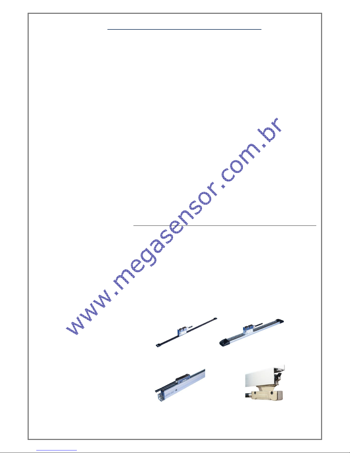
For the best performance please use ATEK Linear Encoders. ATEK MLS
Series magnetic linear scales present to their users high accuracy and
usage advantages. The magnetic systems never influenced negatively from
the environmental conditions as dust, chip, humidity and cutting fluid, they
work without any problem. Because of the contactless working there is no
friction, they have unlimited lead time mechanically, they work without
any mechanical problem and maintenance.
ATEK advice you 4 different magnetic linear encoders:
1. MLS 1 2. MLS 2
3. MLS 3 4. PS 1
[4]
2. TECHNICAL PARAMETERS
TECHNICAL SPECIFICATIONS
Axis Number
2, 3, 4
Display
8 Digit + 1 Sign (-) Digit, Green, Touring (-) Sign
Display Resolution
0.1 µm, 0.2 µm, 0.5 µm, 1 µm, 5 µm, 10 µm, 25 µm
Or the user can designate as requested.
Input Signal
Available Push Pull or TTL
A,B,Z (Line Driver A, B, Z, /A, /B, /Z) Incremental Encoder Signals
Mass
2,7 Kg
Power Supply Voltage
85 – 265 V AC 50/60Hz.
Storage Temperature
- 25 ~ 65 °C
Operation Temperature
-10 ~ 45 °C
Relative Humidity
%20 - %85
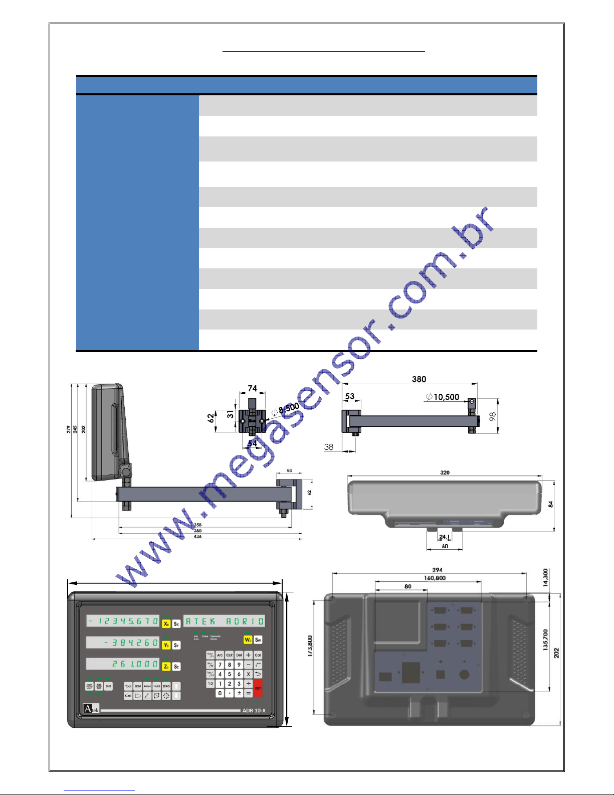
Dimensions
( H x W x T )
202mm x 320mm x 84mm
Housing
Aluminum Injection Housing
Diameter Limits
- 99999,999 mm ~ 99999,999 mm
320
202

[5]
Metric / Inch
measurement selection
Absolute / Incremental
Mode Selection
Shrink
X Axis Zero Button
Y Axis Zero Button
Z Axis Zero Button
W Axis Zero Button
X Axis Selection
Y Axis Selection
Z Axis Selection
W Axis Selection
Addition
Multipication
Substraction Button
Division
Square Root Button
Equal
ENTER
Sign Changing Button
½ Function Button
Divisor
4 Axis Activation
Button
Calculator
-
Numeric Buttons
Undo
Sleep Mode
X Axis
(Axis 1)
Y Axis
(Axis 2)
Z Axis
(Axis 3)
Info Screen
and W axis
(Axis 4)
Cosinus Function
Sinus Function
Tangant Function
Tool Enter Button
(Lathe)
Screen Renew Ratio and
EDM Function
User Zeros
Recall (lathe)
Trape Angle and
Eccentricity Measurement
Bolt Hole Line
Radius Functions
Travelling Button
Clear Button
Delete
Arc Trigonometric
Function
Decimal Point button
[6]
While Connection;
Never Make Connection Under Energy.
Check the On / Off Switch is “Off”.
Check the power voltage if convenient values.
Use only the power cable which is given with the product.
Check the grounding connections.
Don’t use in strong magnetic field.
Don’t use in high temperature and humidity environments.
Install the display as vertical in the high which user can use the keyboard and see the screen.
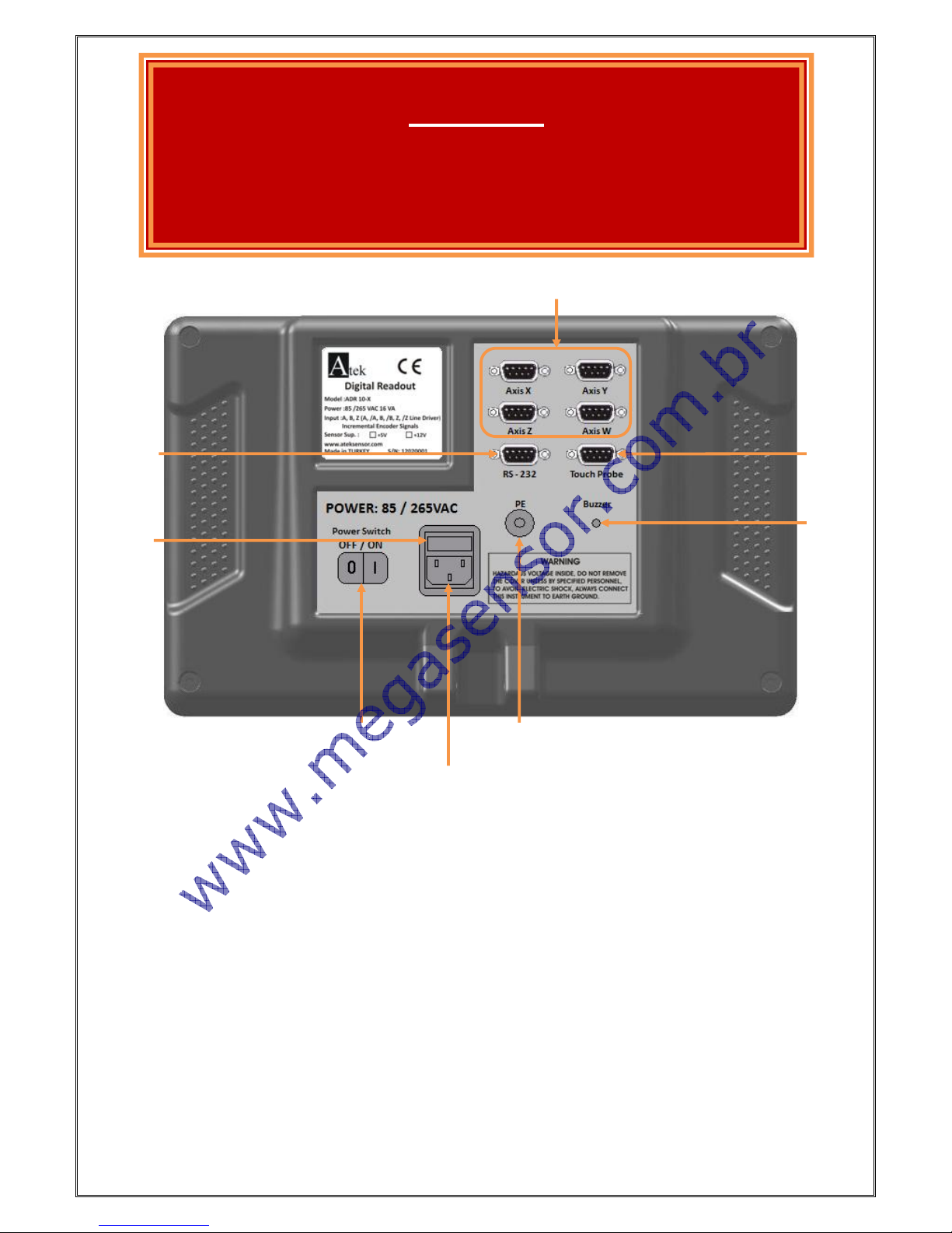
Note: 4 Axis ADR 10-4 Type DRO Gear Panel Wiev.
Contact
Probe
connection
Encoder
Connection
RS -232
Connection
Ground
Connection
Buzzer
Voice
Power Cable
Connection
On / Off
Switch
1A Insure
WARNING!
While installation of the device please switch all
machine energy off and fallow the manual directions.
[7]
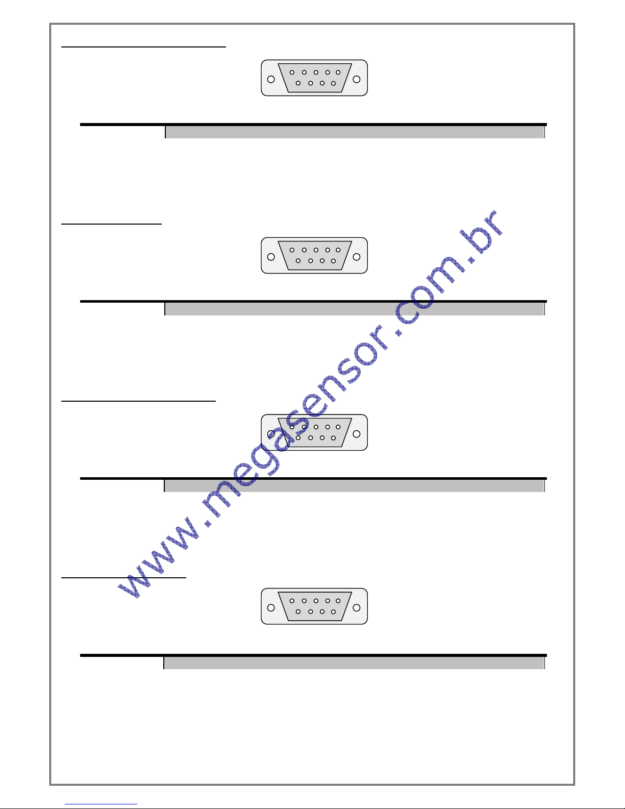
Encoder Connections (Differential)
Encoder Connections
RS – 232Output Port Connection
Contact Probe Connection
Note: While using single contact probe “Signal-” pin must be empty.
Pin Number
1 2 3 4 5 6 7 8 9
Signal
A
/B
+V
0V
/A B /Z
Z
Shield
Pin Number
1 2 3 4 5 6 7 8 9
Signal
A
Empty
+V
0V
Empty
B
Empty
Z
Shield
Pin Number
1 2 3 4 5 6 7 8 9
Signal
Empty
Rx
Tx
Empty
0V
Empty
Empty
Empty
Shield
Pin Number
1 2 3 4 5 6 7 8 9
Signal
Empty+
Empty
+V
0V
Signal-
Empty
Empty
Empty
Shield
1 2 3 4 5 6 7 8 9
1
2 3 4
5
6 7 8
9
1
2 3 4
5
6 7 8
9
1 2 3 4 5 6 7 8 9
[8]
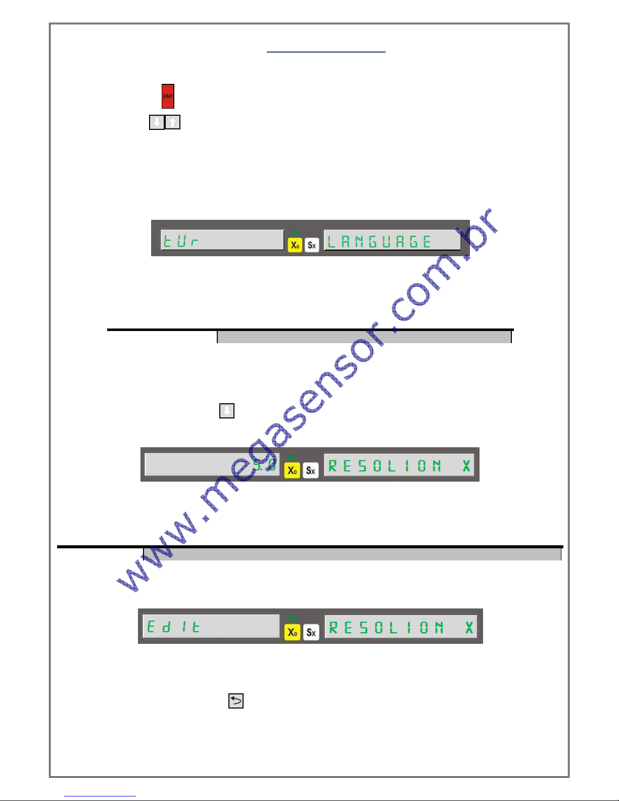
3. SYSTEM SETUP
To enter system setup, when ADR-10 first energized (power connections completed and on/off switch turned “on”)
press “ENTER” button ( ) for a while. You will see “LANGUAGE” word as first when you are in system setup menu.
For MENU traveling buttons can be used.
3.1. Language Selection
It is the first selection of system setup. The numeric buttons can be used for language selection.
In data display “LANGUAGE” and in X axis display language options are written. Language selection can be done by
numeric buttons. After selection please press “ENTER” to save.
3.2. Resolution Setup
After selection language, by pressing button you can enter the resolution setup for X axis. The included
resolution options are displayed as first.
In data screen “RESOLION X” words are seen while the resolution value is seen on X axis. To save the resolutions
please press to enter.
* “9” button is used for user determinate resolution.
To enter user determinate resolution after pressing “9” button please press “ENTER” button. To enter a value press
“Sx” button and enter the resolution value and press enter to save.
You can turn to system setup menu by button.
For the other axes you can repeat the same operation for resolution setup.
Numeric Button
0 1 2 3 4
Language Option
Turkish
English
German
Spanish
Portuguese
Numeric Button
0 1 2 3 4 5 6 7 8
9
Resolution
5 µm
1 µm
2 µm
10 µm
25 µm
0,1 µm
0,2 µm
0,5 µm
*

[9]
Using 4th Axis For Angle Display
For angle measurement with 4th axis (W axis) when you are in “RESOLION W” please press “9” button and press
“ENTER” to enter the pulse number of the encoder. Press “ENTER” again to save. After this in “ADVANCED” menu “W
TYPE” option must be select as 1 – rotary. “ADVANCED” menu will be told detailed in the fallowing pages.
3.3. Direction Setup
It determinates the measuring direction according to encoder movement direction.
For positive measuring direction press “1” button. You will see “1” value in X axis. For negative measuring
direction, please press “0” button. “-1” value will be seen on X axis. Press “ENTER” to save.
You can repeat the same buttons for the other axes.
3.4. Machine Tool Selection
This menu is used to select the type of the machine tool which Digital Readout used on.
Please press “ENTER” button after machine tool selection.
3.5. Compansation Selection
Compansation selection is setup by system setup menu.
By up-down button the “COMPNSTN” writing is found please select linear compensation by “0” button and select
segmented compensation by “1” button. Save the selected compensation by pressing “ENTER” button.
3.6. Advanced Settings
You can receive to Advanced Settings by “ System Setup” menu.
After seeing “ADVANCED” writing press “ENTER” to enter the menu.
Numeric Button
0 1 2 3 4
Machine Type
Milling
Lathe
Grinding
Bohrwerk
Spark
Erosion
[10]
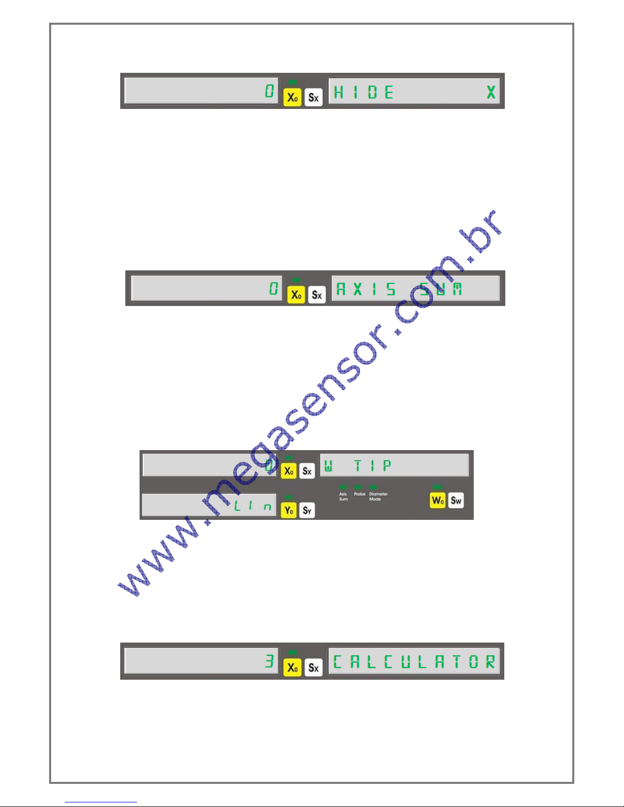
3.6.1. Digit On-Off
It is in the “Advanced Setting” menu.
You can determine the closed digit number by “Hide X” menu . You can close digit numbers up to 5 digits. Please
enter the digit number which will be closed by keyboard and press “ENTER” to save
Please repeat the same way for the other axes.
3.6.2. Axis Addition
Only for lathe and bohrwerk machine tools the axis addition can be used.
You can use this option by “Advanced Setting”
by“1” button you can active and “0” button you can passive. On lathes it adds and Z axis. On bohrwerk machine tools
it adds Z and W axis.
In this menu if addition is active, on lathes Z axis , on Bohrwerks W axis can’t be change by manuel.
3.6.3. 4. Axis Type
The encoder type which will be used on 4. axis means W axis must be enter.
If a rotary encoder will be used press “1” button. On X axis “1” writing and on Y axis “rot” writing will be seen. If a
linear encoder will be used “0” button must be pressed. On X axis “0” writing and on Y axis “Lin” writing will be seen.
3.6.4. Calculator Decimal Setup
This menu determines the decimal number of the calculations on the calculator.
3 or 4 digits can be seen after point. The decimal number can be enter by keyboard. After press “ENTER” to save the
value.

[11]
3.6.5. Probe Logic Level Setup
It can be needed to change according to used probe.
If there is a signal after probe contact (High-Active) must change as “1”, if there is no any signal (Low-Active) must
be change as “0”. Press “ENTER” to save.
3.6.6. Buzzer Close
Buzzer voice can be closed by this menu.
It can be closed by “1” button and can be opened by “0” button.
3.6.7. Return to Factory Settings
It is used to reset all functions changes.
In the menu to return factory settings please press to “Enter” button. “SURE” writing is seen. Press again to
“ENTER”. “WAIT” writing is seen and after a while it turns to fabric setup.
3.7. Test
In system setup menu the device can be tested. You can make display, eeprom test, CPU test, and Relay Test.
Press “Enter” button to enter the menu.
3.7.1. Display Test
It exist in test menu. It can be active by “ENTER” button.
After pressing “Enter” button it clicks all the LED and display segments. Only “Probe” LED can’t be test. To stop the
testing press button.

[12]
3.7.2. Eeprom Test
If Eeprom Works correct when you press “ENTER” button you will see “1” writing.
3.7.3. Keyboard Test
It exist in test menu. You can active it by “ENTER” button.
After activation you have to see different number by for each pressed buttons. To turn back press button.
3.7.4. CPU Test
When you press “Enter” button CPU data can be seen.
On X axis, it shows drawer speed in Hertz unit, on Y axis drawer flash memory in Byte unit , on Z axis RAM in byte
unit.
3.7.5. Relay Test
By pressing “Enter” button this test can be done.
For each “ENTER” pressing the relay will be push and pull.
[13]
4. Basic Functions
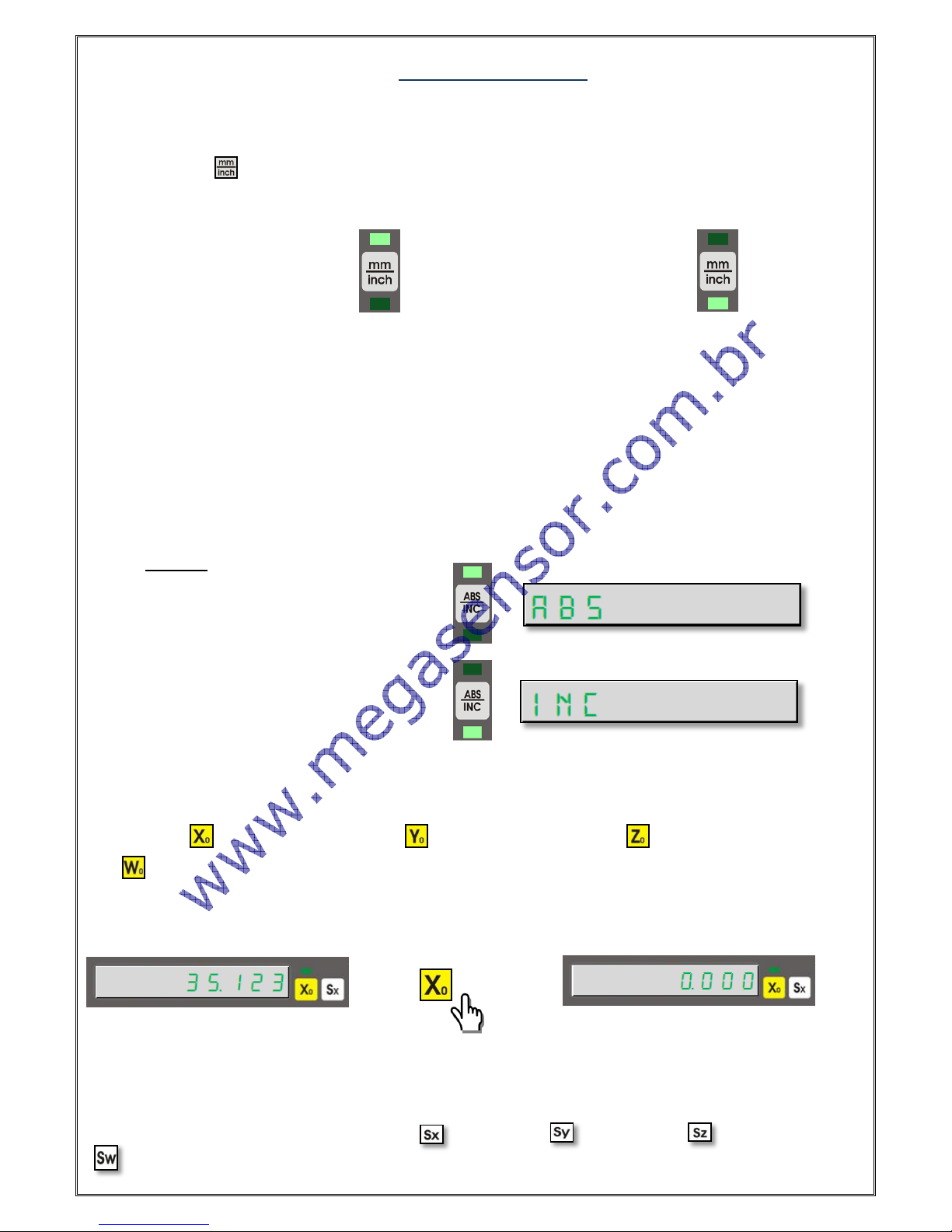
4.1. Measurement System Change
By the button on the keyboard the measurement unit as Metric or Inch system can be selected.
Fort his operation button is used. For each pressing the measurement system is changed. The used
measurement systems can be transfer to the user by LED’s.
Example:
Using Metric Measurement System Using Inch Measurement System
4.2. Operation Mode Selection
Operation Mode can be selected by ABS/INC button on the keyboard. 2 different coordinate display systems are
supported.
- Absolute Operation Mode
- Incremental Operation Mode
For each pressing the operation mode is changed. The used measurement system is transfer to user by
LED’s. In the same time it is showed on data display.
Example:
Using Absolute Operation Mode
Using Incremental Operation Mode
4.3. Quick Zero Axis Values
Axis values can be zero by the zero buttons of the ach axes.
To zero X axis button is used, To zero Y axis button is used, to zero Z axis, button is used and to zero W
axis button is used.
Example: To zero X axis;
4.4. Manuel Value Setting for Each Axis:
It is used to setting value to the axes as manuel.
The axis which will be value setting should be selected by the “Axis Selection Button, the value should be set and
ENTER button should be pressed. To select X axis , to select Y axis to select Z axis and to select W axis
nx button should be pressed and enter is pressed.
[14]
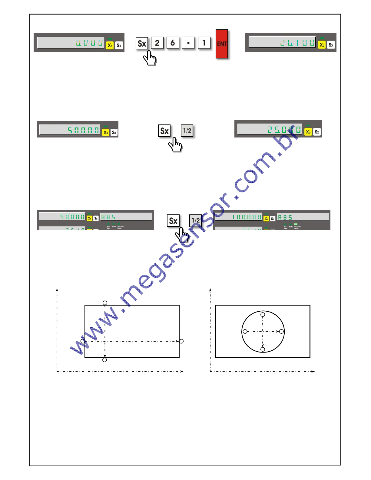
Example: To setting 26.100 mm for X axis;
4.5. Setting Half Value of The Display Value (Milling, Bohrwerk)
With the included keyboard you can get the half value of the axis you want. Firstly the select the axis which you want
to get half value and press ½ function button.
Example: To get half value of the X axis which shows 50.000;
4.6. Diameter Mode (Lathe):
With this mode, designed for lathe machines the measured value is showed as 2 times. It is valid on X axis. To
activate this function X axis is selected and½button is pressed. When the function is active “Diameter Mode” LED
signs.
Example: On X axis which shows 50.000 value to activate diameter mode;
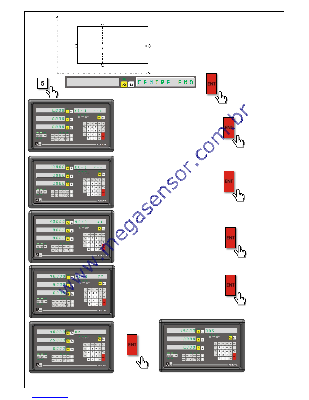
4.7. Center Find (Milling, Bohrwerk)
It is used to find centre of the work piece on XY plane according to teached points. The 4 point of the work piece
must be teached.
Please press “5” button and press enter to enter the function. Contact the tool edge on the first point on X axis as
“Position 1” and press enter to save. Contact the tool edge on Point 2 for position 2 and press enter. For 3 point
contact the tool edge to Point 3 on Y axis for position 3 and press enter. As last contact the tool edge for Point 4 and
press enter to save. You will see “OK” writting on the screen. When you press enter you will see the coordinates to
find the centre by moving. When you move the table up to make zero the coordinates you will be found the centre.
X
Pozisyon 4
Pozisyon 3
Pozisyon 1
Pozisyon 2
Pozisyon 4
Pozisyon 3
Pozisyon 1
Pozisyon 2
X
Y
Y
[15]
Example:
When you move up to reset axis value zero you can find the centre of the work piece.
To find the centre of the drawing on the
left.
Position 4
Position 3
Position 1
Position 2
Y
Tool edge is bringed to
“Position 1”
Tool edge is bringed to
“Position 2”
Tool edge is bringed to
“Position 3”
Tool edge is bringed to
“position 4”
[16]
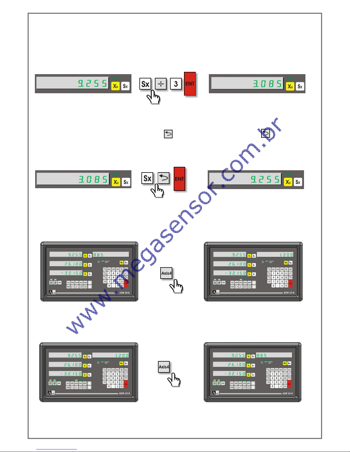
4.8. Simple Calculation on Axis Values:
It is possible to make simple calculation as addition, subtraction, division and multiplication on axis values. It can be
done without activation of calculator. Firstly the axis which the calculation will be done must be selected. Press the
calculation button (+,-,/,* ). And then;
Example: To divide by 3 the X axis value;;
4.9. Undo Function
After transferring the axis value as manuel or after making simple calculations to return the last value this function is
used. For this function firstly select the axis and press button and press enter. If you press button again you
will be canceled the operation.
Example: To turn to old values on X axis;
4.10. Activate the 4th Axis
In 4 axis digital readouts you can activate or deactivate the 4th axis. The axis 4 button is used for this operation
Example: To activate the 4th axis;
Example: To deactivate the 4th axis;
[17]
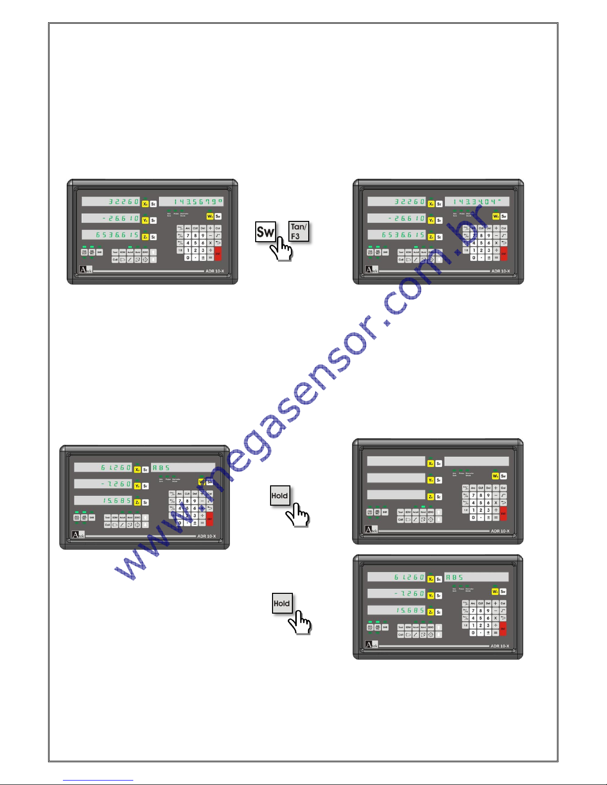
4.11. Display Angle on the 4th Axis
To display angle on 4th axis by “system setting“menu the encoder pulse number must be entered as W resolution.
And again by “system setting “menu, rotary type must be selected. You can also see the this setting on system
setting as detailed.
The angle can be set as Degree or Degree.minute.second. To make passing please press “Sw” button and “Tan/F3”
button accordingly.
Example: To Change Degree Angle as Degree.minute.second;
4.12. Sleep Mode:
When the screen is on sleepy mode all the buttons are turned off except “HOLD” button. By this way 3th Person
interfere will be prevented. Although the buttons are turned off, the signals will be process. If you change the table
place it senses this changing and if in the normal mode it use the last position.
In the brake times and after works the device can be sleepy mode until beginning to work again.
You can pass “Sleepy Mode” by “HOLD” button and it is possible to exit by the same “HOLD” button.
Example: To pass to “Sleepy” mode and to exit;
[18]
5. ADVANCED FUNCTIONS
5.1. To Find Zero Point of the Machine Tool
It is used not to lost time by measuring the work pieces one by one. The zero point will not be deleted after energy
cuttings. But for the high accuracy it will be better to revise for each new starts.
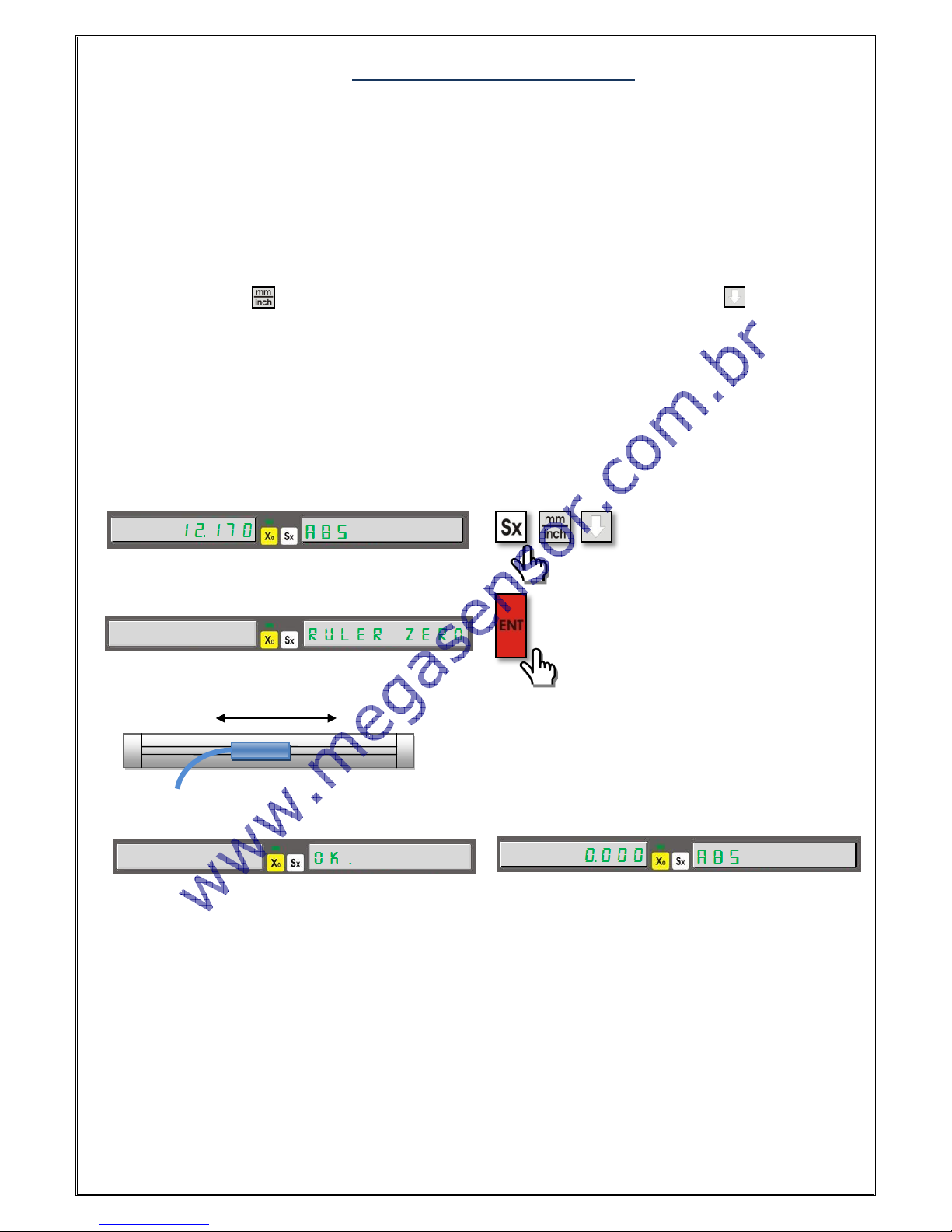
5.1.1. Ruler Zero Point: To set the ruler zero press the button which selects the axis and press the
button . You will see the compensation screen. To pass this screen press button. On the
information Screen you will see the “RULER ZERO” writing. Please press enter and move the scale to
see “OK” writing on the screen and you will exit in one second from the function.
Example: To find ruler zero point on X axis;
The zero point will be found by these steps.
Move the scale to find the zero point
[19]
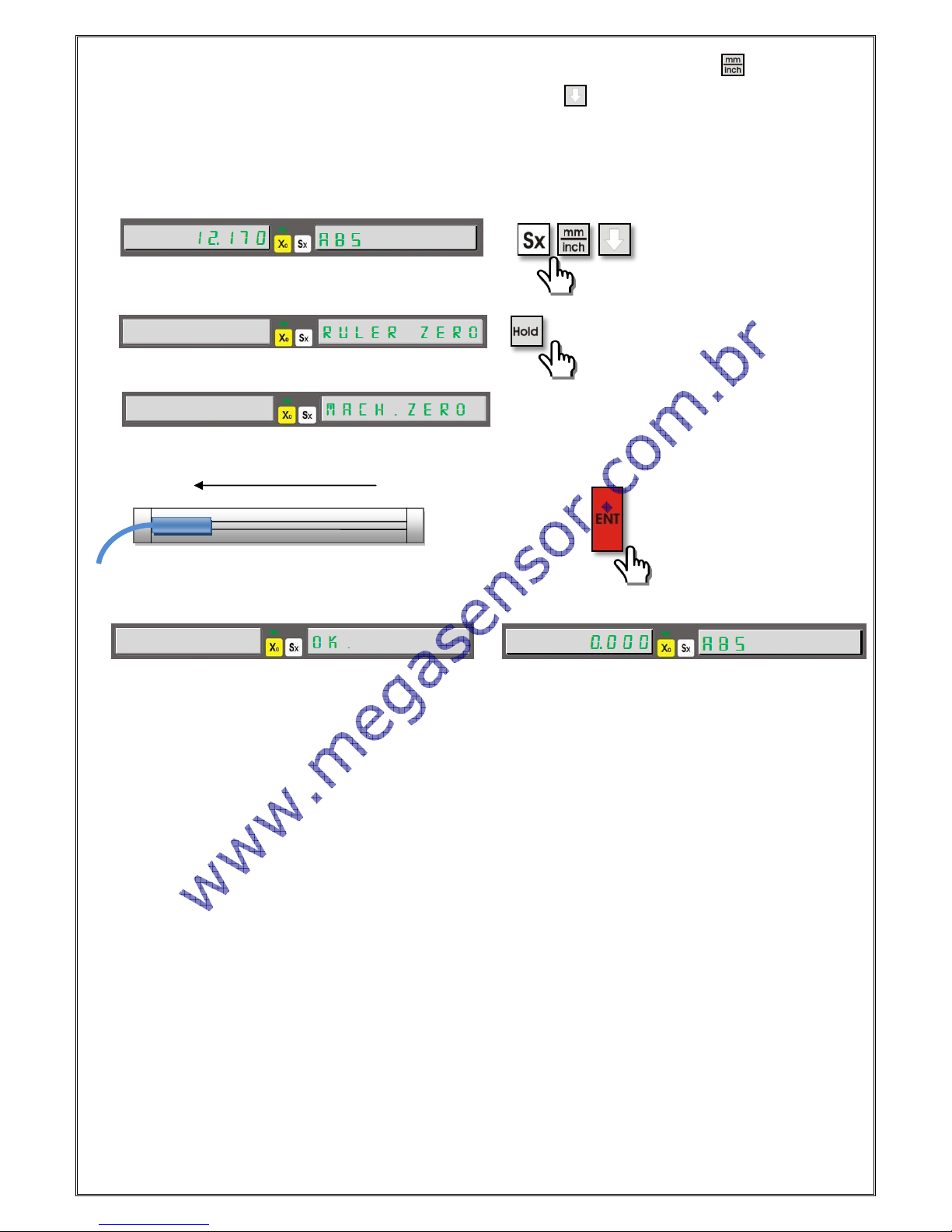
5.1.2. Mechanical Zero Point: Please select the axis which will be zero and press button. You will
see the compensation screen. To pass please press button. When you see “RULER ZERO”
writing press “HOLD” button. Then you will see “MACH. ZERO” writing. Move the scale the end point
of left side and press “ENTER” to save.
The mechanical zero point will be found by these steps.
Move the
scale to end
of left side
 Loading...