

Page 1

Instruction Manual
VITS100
NTSC VITS Inserter
070-8333-02
Warning
The servicing instructions are for use by qualified
personnel only. To avoid personal injury, do not
perform any servicing unless you are qualified to
do so. Refer to all safety summaries prior to
performing service.
Page 2

Specifications
This section contains tables that list the specifications for the VITS100 NTSC
VITS Inserter. All specifications are guaranteed unless noted “typical.”
The performance limits in this specification are valid with these conditions:
H The VITS inserter must have been calibrated/adjusted at an ambient
temperature between +20
H The VITS inserter must be in an environment with temperature, altitude,
humidity, and vibration within the operating limits described in these
specifications.
H The VITS inserter must have had a warm-up period of at least 20 minutes.
Specification Tables
T able 3–1: Program channel characteristics
Characteristic Information
_ C and +30_ C.
Gain Unity ± 1%
Frequency Response ±1% to 5.5 MHz
±3% to 10 MHz
Chrominance-to-Luminance Gain ±0.5%
Chrominance-to-Luminance Delay ≤5 ns
Diff Phase ≤0.2°
Diff Gain ≤0.2%
Line Tilt ≤0.5%
DC Output Level 0 V ±10 mV
DC Matching of Inserted Test Signal to
Program Signal
Phase Match (Relay Bypass Path to Signal
Processing Path)
Hum Rejection 50 dB (Measured right after burst)
Keyboard (No Noise) Too small to measure on VM700A
Insertion Transients ≤10 mV (Measured on Tektronix 1780R. Typically <5 mV)
Input Impedance 75 W
Return Loss 36 dB to 5 MHz (Program In, Program Out, and Monitor Out)
±3 mV
±1° at F
SC
VITS100 NTSC VITS Inserter Instruction Manual
3–1
Page 3

Specifications
T able 3–1: Program channel characteristics (Cont.)
Characteristic Information
Phase Matching of Inserted Test Signal to
Program Video
Pulse to Bar Ratio 100%±0.5% (Typically within ±0.25%)
Signal to Noise Ratio >70 dB (Unweighted Filter at 5 MHz. Measured 91 dB on VM700A, relative to reference)
±1° (Program Sync and Burst Normal Level)
T able 3–2: Test Signal and Black Burst general characteristics
Characteristic Information
Frequency Response ±1% to 5 MHz
±5% to 10 MHz
Luminance Amplitude Accuracy ±1%
Chrominance-to-Luminance Gain ±0.5%
Chrominance-to-Luminance Delay ≤5 ns
Diff Phase ≤0.3°
Diff Gain ≤0.3%
Line Tilt ±0.5%
Output Impedance 75 W
Signal to Noise Ratio >78 dB (Measured on a VM700A with an unweighted 5 MHz lowpass filter.)
Spurious Signals (5 MHz 50 MHz)
Pulse to Bar Ratio 100% ±0.5%
K Factor (K2T) 0.3% (Typically 0.2%)
Crosstalk ≥60 dB down
DC Offset 0 V DC ±10 mV
SCH Phase Accuracy 0 ±5° (< ±2.5° typical)
Luminance Rise Time 140 ns ±20 ns
Chrominance Rise Time 300 ns ±35 ns
>55 dB down
T able 3–3: Black and Gray Test Signal characteristics
Signal Information
0% Black 0 IRE Luminance with sync and burst; see Figure 3–1.
7.5% Black 7.5 IRE Luminance with sync and burst; see Figure 3–2.
50% Gray 50 IRE Luminance with sync and burst; see Figure 3–3.
3–2
VITS100 NTSC VITS Inserter Instruction Manual
Page 4

T able 3–4: FCC Composite characteristics
Characteristic Information
Timing See Figure 3–5
Modulated 5-step Staircase
Luminance
Amplitude 80.4 IRE ±0.7 IRE
Riser Amplitude 1/5 of 5-step amplitude ±0.5%
Rise Time 250 ns ±25 ns
Chrominance
Phase Same as burst ±0.3°
Envelope Risetime 375 ns ±37.5 ns
2T Pulse
Pulse-to-Bar Ratio 100% ±0.5%
Half Amplitude Duration (HAD) 250 ns ±25 ns
Ringing 1.0 IRE or less
Modulated SIN2 Pulse
Pulse-to-Bar Peak Amplitude 100%
Half Amplitude Duration 1.563 ms ±150 ns
Phase 60.8° ±1°
Bar
Amplitude 100 IRE ±1 IRE
Rise Time 250 ns ±25 ns
Specifications
VITS100 NTSC VITS Inserter Instruction Manual
3–3
Page 5
Specifications
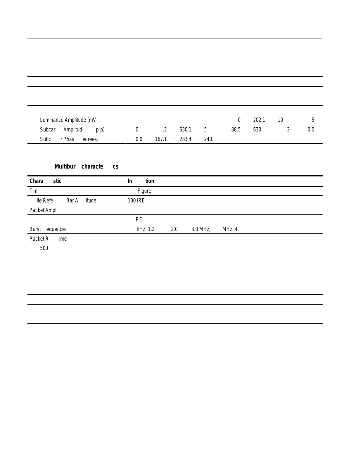
T able 3–5: FCC Color Bars characteristics
Characteristic Information
Timing See Figure 3–4
Luminance Rise Time 250 ns ±25 ns
Bar Characteristics: White Y ellow Cyan Green Magenta Red Blue Black
Luminance Amplitude (mV p-p)
Subcarrier Amplitude (mV p-p)
Subcarrier Phase (degrees)
714.3
0.0
0.0
494.3
444.2
167.1
400.7
630.1
283.4
345.7
588.5
240.8
256.0
588.5
60.8
202.1
630.1
103.4
107.8
444.2
347.1
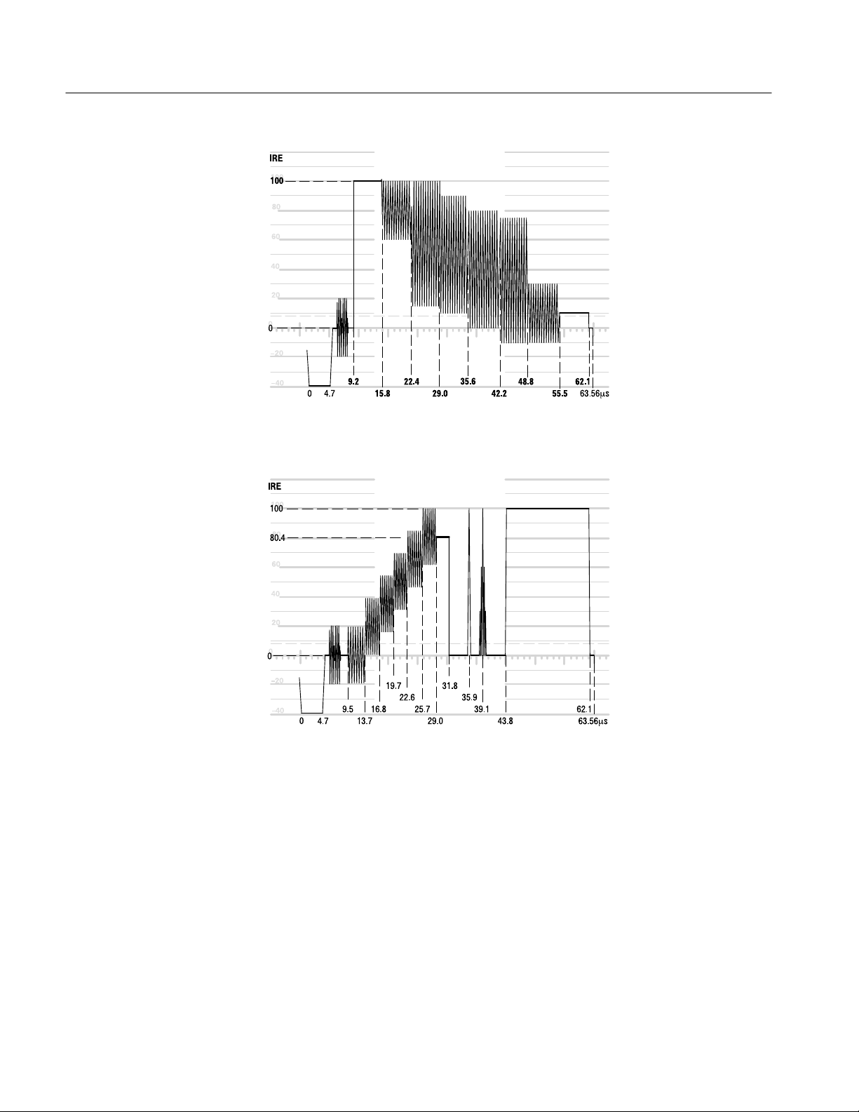
T able 3–6: Multiburst characteristics
Characteristic Information
Timing See Figure 3–6
White Reference Bar Amplitude 100 IRE
Packet Amplitudes 60 IRE p-p
Pedestal 40 IRE
Burst Frequencies 500 kHz, 1.25 MHz, 2.0 MHz, 3.0MHz, 3.58 MHz, 4.1 MHz
Packet Rise Time
500 kHz 140 ns typical (sin2 shaped packets)
Other Packets 400 ns typical (sin2 shaped packets)
53.5
0.0
0.0
T able 3–7: Multipulse characteristics
Characteristic Information
Timing See Figure 3–7
Amplitudes 80 IRE
Frequencies 1.0 MHz, 2.0 MHz, 3.0 MHz, 3.58 MHz, and 4.2 MHz
3–4
VITS100 NTSC VITS Inserter Instruction Manual
Page 6

T able 3–8: NTC7 Combination characteristics
Characteristic Information
Timing See Figure 3–8
White Reference Bar
Amplitude 100 IRE ±0.7 IRE
Rise Time 250 ns ±25 ns
Multiburst Packets
Amplitude 50 IRE ±0.5 IRE p-p
Average Level 50 IRE ±0.5 IRE
Frequencies 500 kHz, 1.0 MHz, 2.0 MHz, 3.0 MHz, 3.58 MHz, 4.2 MHz
Packet Rise Time
500 kHz and 1.0 MHz 140 ns typical (sin2 shaped packets)
Other Frequencies 400 ns typical (sin2 shaped packets)
Modulated Pedestal
Pedestal
Amplitude 50 IRE ±0.5 IRE
Rise Time 250 ns ±25 ns
Chrominance
Amplitude
20 IRE 20.01 IRE ±0.5 IRE
40 IRE 40.02 IRE ±0.5 IRE
80 IRE 80.04 IRE± .5 IRE
Phase relative to burst 90° ±0.5°
Rise Time 400 ns ±40 ns
Specifications
VITS100 NTSC VITS Inserter Instruction Manual
3–5
Page 7

Specifications
T able 3–9: NTC7 Composite characteristics
Characteristic Information
Timing See Figure 3–9
Modulated 5-step Staircase
Luminance
Amplitude 90.2 IRE ±0.7 IRE
Riser Amplitude 1/5 of 5-step amplitude ±0.5%
Rise Time 250 ns ±25 ns
Chrominance
Phase Same as burst ±0.3°
Envelope Risetime 400 ns ±40 ns
2T Pulse
Pulse-to-Bar Ratio 100% ±0.5%
Half Amplitude Duration (HAD) 250 ns ±25 ns
Ringing 1.0 IRE or less
Modulated SIN2 Pulse
Pulse-to-Bar Peak Amplitude 100%
Half Amplitude Duration 1.563 ms ±150 ns
Phase 60.8° ±1°
Bar
Amplitude 100 IRE ±1 IRE
Rise Time 125 ns ±15 ns
T able 3–10: Red Field characteristics
Characteristic Information
Timing See Figure 3–10
Luminance
Amplitude, Standard 202.2 mV ±1%
Amplitude, Option 1J 160.72 mV ±1%
Rise Time 250 ns ±25 ns
Chrominance
Amplitude, Standard 630.1 mV ±1%
Amplitude, Option 1J 681.23 mV ±1%
Phase 103.4° ±0.3°
Rise Time 400 ns ±40 ns
3–6
VITS100 NTSC VITS Inserter Instruction Manual
Page 8

T able 3–11: SIN X/X characteristics
Characteristic Information
Timing See Figure 3–1 1
Bandwidth 4.75 MHz
Pedestal 24 IRE
Peak 90 IRE (Peak amplitude from pedestal )
T able 3–12: Vertical Interval Reference Signal characteristics
Characteristic Information
Timing See Figure 3–12
Chrominance Reference
Amplitude 40 IRE
Phase Same as burst ±0.3°
Envelope Rise Time 1 ms ±100 ns (sin2 shaped)
Average Chrominance Level 70 IRE
Luminance Reference
50 IRE Level 50 IRE
Black Reference 7.5 IRE
Specifications
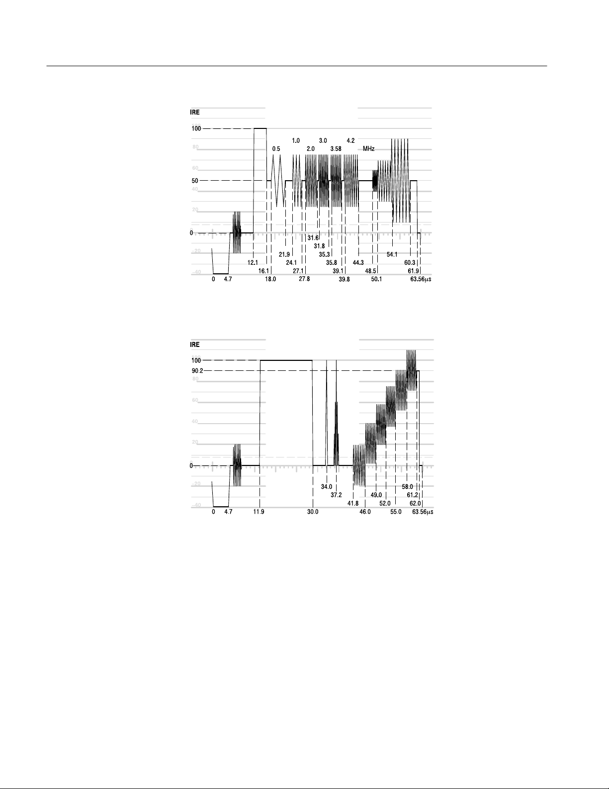
T able 3–13: Cable Multiburst (Option 2) characteristics
Characteristic Information
Timing See Figure 3–13
White Reference Bar Amplitude 60 IRE
Packet Amplitudes 60 IRE
Pedestal Amplitudes 30 IRE
Burst Frequencies 500 kHz, 1.25 MHz, 2.0 MHz, 3.0 MHz, 3.75 MHz, 4.0 MHz
Packet Rise Time
500 kHz Packet 140 ns typical (sin2 shaped packets)
Other Packets 400 ns typical (sin2 shaped packets)
VITS100 NTSC VITS Inserter Instruction Manual
3–7
Page 9

Specifications
T able 3–14: Cable Sweep (Option 2) characteristics
Characteristic Information
Timing See Figure 3–14
Pedestal Amplitude 50 IRE
Sweep Amplitude 100 IRE
Sweep Start Frequency 0.1 MHz
Sweep End Frequency 4.2 MHz
T able 3–15: Genlock characteristics
Characteristic Information
Burst Lock
Genlock Phase Change with Input
Amplitude
Genlock Phase Change with Input
Signal APL
Genlock Phase Change with Input
Signal Burst Frequency
Lock Range
Frequency , Standard 3.579545 MHz ±20 Hz (NTSC)
Fequency, Option 1M 3.575611 MHz ±20 Hz (PAL-M)
Amplitude +6 dB to –12 dB (Typically to –16 dB NTSC; –14 dB P AL-M)
Genlock Phase Jitter with Input Amplitude
Change
≤2° burst phase change for input sync or burst amplitude range of 287mV ±3 dB
≤4° burst phase change for amplitude range of 287mV ±6dB
(For either composite video or burst amplitude errors)
≤1° burst phase change over 10% to 90% APL
≤1° burst phase change for ±20 Hz change in incoming subcarrier
Typically ≤0.2° peak for input sync or burst amplitude range of 287 mV ±3dB; no noise
on input signal
Typically ≤0.4° peak for input amplitude range of 287 mV ±6 dB; no noise on input signal
Sync Lock Jitter ≤10 ns for input sync amplitude range of 287 mV ±3 dB (No noise on input signal)
Noise Performance Locks to 28 dB S/N Ratio Video
3–8
VITS100 NTSC VITS Inserter Instruction Manual
Page 10

Specifications
T able 3–16: Power Supply characteristics
Characteristic Information
Output Voltages +5 V ±200 mV from 1A to 3 A (voltage adjustable)
–5.2 V ±300 mV from 0.5 A to 1 A
±12 V ±120 mV from 0.05 A to 0.2 A (post regulated from ±14.5 V by linear regulators)
Output Ripple
+5 V ≤50 mV switching ripple,
≤5 mV line frequency ripple
–5.2 V ≤50 mV switching ripple,
≤10 mV line frequency ripple
±12 V ≤10 mV switching ripple,
≤5 mV line frequency ripple
Line Input Range Regulates from 90 to 250 VAC
Minimum Load 10 W minimum load required to operate. However, output voltages other than +5 V may
not meet specifications outside the listed currents. At zero load the power supply cycles
on and off
Power Consumption 40–50 W.
Overvoltage Protection The 5 V output is protected by a crowbar circuit that engages at approximately 5.7 V.
Overvoltage protection causes the power supply to cycle by engaging the primary side
current limit time-out circuit
Power 70 W maximum controlled by primary side current limit circuits. Power supply cycles on
and off when power limit is reached
Short-Circuit Protection All outputs are protected by the primary side current limit and time-out circuits. In
addition, the ±12 V outputs are limited to 1 A by the linear regulators
Efficiency 70% nominal
Fan Drive 15 V to 16.5 V, as determined by supply load
T able 3–17: Physical characteristics
Characteristic Information
Height 1.734 in (4.404 cm)
Width 8.1 in (20.6 cm)
Length 17.2 in (43.7 cm)
Weight
Net 4.7 lbs (2.1 kg)
Shipping 16.7 lbs (7.6 kg)
VITS100 NTSC VITS Inserter Instruction Manual
3–9
Page 11

Specifications
T able 3–18: Environmental characteristics
Characteristic Information
Temperature
Non-Operating –40° to +65° C (–40° to +149° F)
Operating 0° to +50° C (32° to 122° F)
Altitude
Non-Operating To 50,000 ft (15,240 m)
Operating To 15,000 ft (4,572 m)
Vibration (Operating) Fifteen minutes each axis at 0.025 inch, frequency varied from 10-55-10 Hz in 4-minute
cycles with the instrument secured to the vibration platform; ten minutes each axis at any
resonant point, or at 55 Hz.
Shock 50 G, 1/2 sine, 11 ms duration, three guillotine shocks per side
Transportation Qualified under NTSB Test Procedure 1A, Category II (36-inch drop)
3–10
VITS100 NTSC VITS Inserter Instruction Manual
Page 12

T able 3–19: Certifications and compliances
Category Standards or description
Specifications
EC Declaration of Conformity –
EMC
Australia/New Zealand
Declaration of Conformity – EMC
EMC Compliance Meets the intent of Directive 89/336/EEC for Electromagnetic Compatibility when it is used with the
FCC Compliance Emissions comply with FCC Code of Federal Regulations 47, Part 15, Subpart B, Class A Limits.
Installation (Overvoltage)
Category
Pollution Degree A measure of the contaminates that could occur in the environment around and within a product.
Safety Standards
U.S. Nationally Recognized
Testing Laboratory Listing
Canadian Certification CAN/CSA C22.2 No. 231 CSA safety requirements for electrical and electronic measuring and
European Union Compliance Low Voltage Directive 73/23/EEC, amended by 93/69/EEC
Meets intent of Directive 89/336/EEC for Electromagnetic Compatibility. Compliance was
demonstrated to the following specifications as listed in the Official Journal of the European Union:
EN 50081-1 Emissions:
EN 55022 Class B Radiated and Conducted Emissions
EN 50082-1 Immunity:
IEC 801-2 Electrostatic Discharge Immunity
IEC 801-3 RF Electromagnetic Field Immunity
IEC 801-4 Electrical Fast Transient/Burst Immunity
Complies with EMC provision of Radiocommunications Act per the following standard(s):
AS/NZS 2064.1/2 Industrial, Scientific, and Medical Equipment: 1992
AS/NZS 3548 Information T echnology Equipment: 1995
product(s) stated in the specifications table. Refer to the EMC specification published for the stated
products. May not meet the intent of the directive if used with other products.
Terminals on this product may have different installation (overvoltage) category designations. The
installation categories are:
CA T III Distribution-level mains (usually permanently connected). Equipment at this level is
typically in a fixed industrial location.
CA T II Local-level mains (wall sockets). Equipment at this level includes appliances, portable
tools, and similar products. Equipment is usually cord-connected.
CA T I Secondary (signal level) or battery operated circuits of electronic equipment.
Typically the internal environment inside a product is considered to be the same as the external.
Products should be used only in the environment for which they are rated.
Pollution Degree 2 Normally only dry, nonconductive pollution occurs. Occasionally a
temporary conductivity that is caused by condensation must be
expected. This location is a typical office/home environment.
Temporary condensation occurs only when the product is out of
service.
UL1244 Standard for electrical and electronic measuring and test equipment.
test equipment.
EN 61010-1 Safety requirements for electrical equipment for measurement,
VITS100 NTSC VITS Inserter Instruction Manual
control, and laboratory use.
3–11
Page 13

Specifications
T able 3–19: Certifications and compliances (Cont.)
Category Standards or description
Additional Compliance IEC61010-1 Safety requirements for electrical equipment for measurement,
control, and laboratory use.
Safety Certification Compliance
T emperature, operating +5 to +40_ C
Altitude (maximum
operating)
Equipment Type T est and measuring
Safety Class Class 1 (as defined in IEC 1010-1, Annex H) – grounded product
Overvoltage Category Overvoltage Category II (as defined in IEC 1010-1, Annex J)
Pollution Degree Pollution Degree 2 (as defined in IEC 1010-1). Note: Rated for indoor use only.
2000 meters
Waveform Diagrams
The diagrams in Figures 3–1 through 3–14 contain timing information for the
various test signals generated by the VITS100 NTSC VITS Inserter and
described in Tables 3–3 through 3–14.
Figure 3–1: 0% Black
3–12
VITS100 NTSC VITS Inserter Instruction Manual
Page 14

Figure 3–2: 7.5% Black
Specifications
Figure 3–3: 50% Gray
VITS100 NTSC VITS Inserter Instruction Manual
3–13
Page 15
Specifications
Figure 3–4: FCC Color Bars
3–14
Figure 3–5: FCC Composite
VITS100 NTSC VITS Inserter Instruction Manual
Page 16
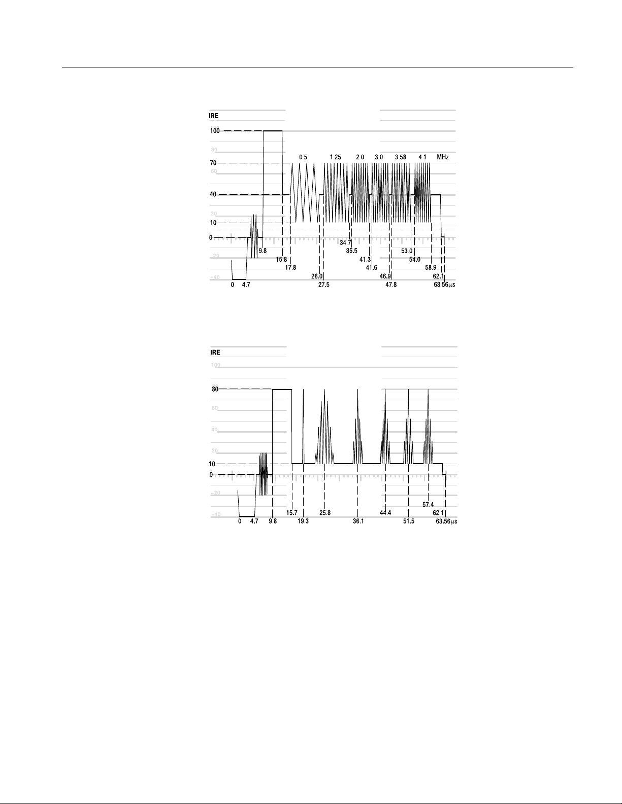
Figure 3–6: Multiburst
Specifications
Figure 3–7: Multipulse
VITS100 NTSC VITS Inserter Instruction Manual
3–15
Page 17
Specifications
Figure 3–8: NTC7 Combination
3–16
Figure 3–9: NTC7 Composite
VITS100 NTSC VITS Inserter Instruction Manual
Page 18
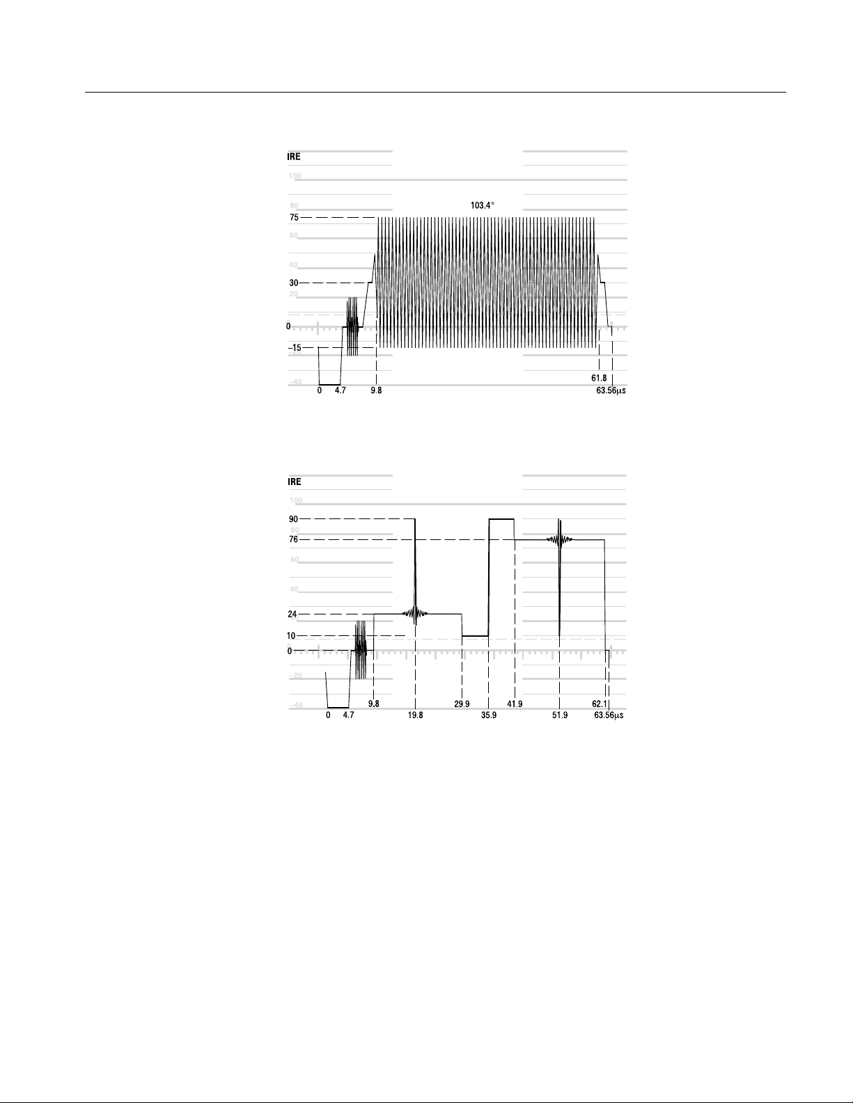
Figure 3–10: Red Field
Specifications
Figure 3–11: SIN X/X
VITS100 NTSC VITS Inserter Instruction Manual
3–17
Page 19

Specifications
Figure 3–12: VIRS
3–18
Figure 3–13: Cable Multiburst
VITS100 NTSC VITS Inserter Instruction Manual
Page 20

Figure 3–14: Cable Sweep
Specifications
VITS100 NTSC VITS Inserter Instruction Manual
3–19
 Loading...