

Page 1
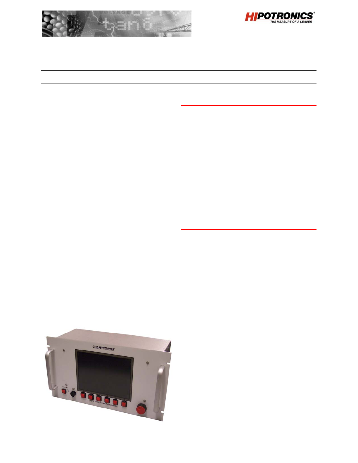
Time Domain Reflectometer
TDR 1170
Hipotronics TDR1170 — The unique features and
new technology used in the TDR 1170 make it the
most flexible and easiest to use instrument available
for advanced cable fault location. The TDR 1170
features an automatic configuration, which can be
modified as necessary. All cable fault data can be
stored and retrieved at any time, ensuring time
savings, consistency and accuracy from one crew to
the next.
The digital TDR 1170 will locate and identify short
circuit (bolted) faults, low resistance shunt faults, open
circuits, high resistance series faults, wet sections,
splices, transformers, cable transitions, and concentric
neutral corrosion. To locate high resistance,
intermittent and flashover faults, the TDR 1170 is
designed to measure in the digital arc reflection,
current impulse, voltage decay, and all differential fault
locating modes. The selection of fault location method
allows the operator to select the method which they
are most familiar with or the method that is most
appropriate for the type of cable and type of fault that
is encountered.
The TDR 1170 requires a high voltage coupler to
interface to a cable fault locator (thumper). The cable
fault locator then provides the voltage and current to
enable the TDR 1170 to quickly and definitively locate
cable faults.
Included with the TDR 1170 is a software package to
allow the stored data to be viewed on a PC and also be
printed and analyzed by office personnel or training
teams.
FEATURES
; Digital High Voltage TDR
; 5 Methods of Fault Location
; Arc Reflection
; Impulse Current
; Voltage Decay
; Differential Methods
; Low Voltage
; Color LCD Screen
; PC Software
; SVGA Output for External Monitor
BENEFITS
Pre-Locate Faults
Diagnose Cable Faults
Easy to Use
Compatible with Common “Thumpers”
Provides Long-Term Storage and Evaluation
Cable System Signature Mapping
Reduce Outage Time
Reduce Cable Damage
Simplified Operator Training
Subject to technical modifications without notice. TDR1170-DS / 07.2004
Page 2
TECHNICAL SPECIFICATIONS
General
Input Voltage: 90 to 250 V AC, 50/60Hz VP Range: 98ft./µs to 492ft./µs
Accuracy: < + 1% of cable length Pulse Amplitude: 25 V into 50W
Measuring Range: 1 ft. to 160,000 ft. Pulse Width: 50ns to 10µs
Units of Measure: Feet, Yards, Meters Sample Rate: 12.5 to 30ms
Trigger Delay: 1 to 30ms Memory Modes: 32 sets of 1 or 3 phase
Setup: 16 setup options RS232 Port: Download traces to PC
Monitor: LCD Display 10 inch
diag.
Weights and Dimensions (W x H x D, net weight, ship weight)
Standard 19” rack 19” x 10.5” x 7” (48 x 26 x 18 cm) 18 lbs (8.2 kg) lbs (kg)
SCOPE OF SUPPLY
Qty.1 TDR1170 in standard 19” rack mount cabinet
Qty.4 RG58/U BNC-BNC cable
Qty.1 Serial interface cable and input line cord
Qty.1 Operations Manual and TDR-PC interface software
ORDERING INFORMATION
System
Time Domain Reflectometer TDR1170-A
TDR1170-B
Accessories
HV Coupler HVC4100 series
Cable Fault Locating (Thumper) CF or CET series
Cable Reels
Accessory Connectors
8100
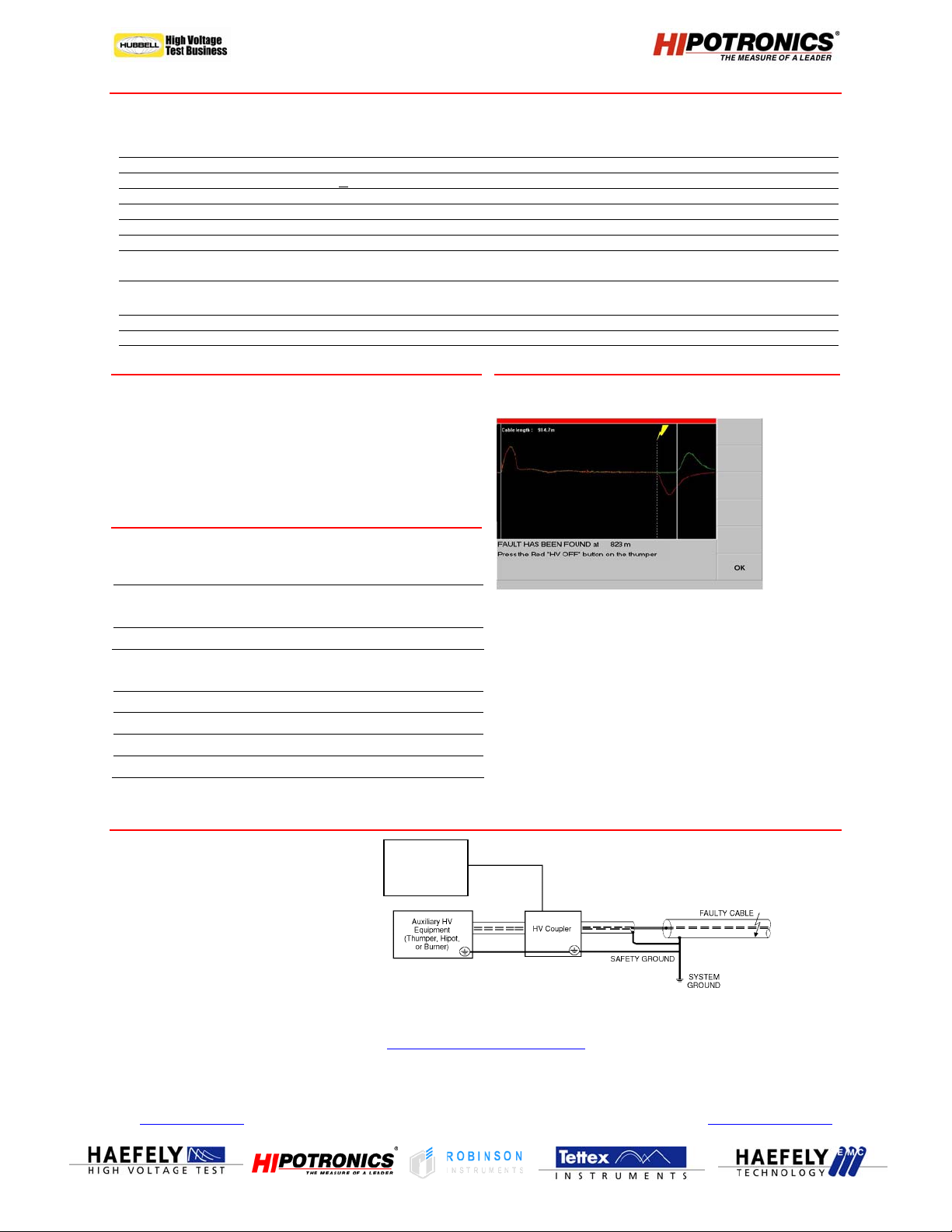
SYSTEM DISPALY
MEASURING SETUP DIAGRAM
European Contact Locate your local USA Contact
Haefely Test AG
Lehenmattstrasse 353
CH-4028 Basel
Switzerland
+ 41 61 373 4111
+ 41 61 373 4912
| sales@haefely.com
Cable Radar
(TDR)
Model 1170
sales representative at
www.high-voltage-hubbell.com
Hipotronics Inc.
Brewster, NY 10509 USA
| sales@hipotronics.com
1650 Route 22
PO Box 414
+ 1 845 279 8091
+ 1 845 279 2467
Hipotronics has a policy of continuous product improvement. Therefore we reserve the right to change design and specification without notice TDR1170-DS / 04.2009
 Loading...