

Page 1
EFG-3 1000 watts
EFG-3B 2000 watts
INSTRUMENTS FOR INDUSTRY INC.
903 South Second Street, Ronkonkoma, NY 11779
Tel: 631-467-8400 • Fax: 631-467-8558 • E mail: sales@ifi.com
www.ifi.com
E-Field Generating
Antenna
EFG-3/EFG-3B
SERIES
Presents a uniform load to driving power source
Provides broad area of useful field
High RF power to E-Field conversion efficiency
Parallel plate mode for high E-Field testing
Ideal for automatic swept field
susceptibility testing
Suitable for intensive testing for small objects
less than 1/2 meter in their longest dimension
Features Include:
Features Include:
Power Handling Capability: Up to 1000 watts
continuous CW input, 2000 watts forEFG-3B
Frequency Range: 10kHz to 220 MHz
Input Impedance: 50 ohms nominal
Output Port Impedance: 50 ohms nominal
VSWR: Less than 4:1 at all frequencies,
reflections included
Physical Size: Main antenna element:
1 meter x 1 meter x 10 centimeters (LxWxD)
Load Required: 50 ohm, standard coaxial
termination, with power rating appropriate for
source
Connectors: Type N Female (EFG-3)
Type C Female (EFG-3B)
Specifications:
Specifications:
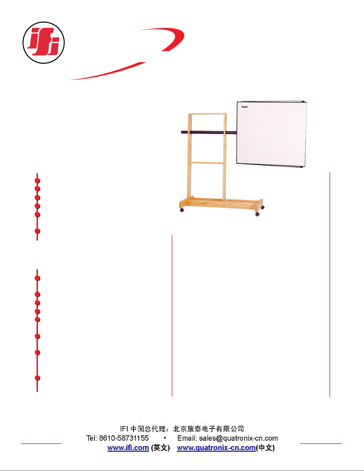
The EFG-3 E-Field generating antenna is designed to generate
strong electric field intensities within its vicinity for use in
radiated susceptibility testing systems.
The EFG-3 provides a means for dissipating any unused power
through the use of a conventional coaxial 50 ohm termination
of appropriate power handling capability. This allows the EFG3 to handle up to 1000 watts of continuous power.
The EFG-3 is able to perform in such an efficient manner due
to its physical configuration as a radiating transmission line.
Highly efficient and conservatively rated broadband
transformers are used for impedance matching. This unique
matching configuration allows the best possible power to field
conversion efficiency by stepping up the source voltage to twice
the input value.
The EFG-3 can be rotated on its boom axis for both vertical
and horizontal polarization and can be combined in multiple
bank arrays for an increased useable test area.
Pivoting extensions of the top and bottom edges provide
access to the area of highest voltage differential such that E-Field
intensity can be maximized for testing small objects under
extreme field conditions, typically several hundreds volts per
meter.
The EFG-3 offers a matched load to the driving source over
its entire useable frequency range.
Description:
Description:
Page 2
The EFG-3 radiating system is small enough to be physically
manageable and portable, but large enough to provide efficient
conversion of RF power into a uniform electric field over a
useful physical area. This high efficiency is obtained in several
ways. As shown in Fig. 1, broadband transformers are used to
step up the 50 ohm input impedance to 200 ohms. This is the
design impedance of the terminated loop antenna system.
Voltage between the upper and lower edges of the antenna
system then becomes approximately twice that of the driving
source. For example, a 25 watt power source will cause a 54
volt rms differential, after passing through the step up
transformer.
Since the upper and lower edges of the antenna are spaced
at 1 meter, any point in the plane of the antenna (and between
these two edges) will have an E-Field gradient of
twice the applied voltage, measured in volts per
meter.
Furthermore, the upper and lower edges of the
EFG-3 are equipped with pivoting projections that
can be used to form an extended transmission line
mode of operation at the outer surface of the antenna. Small objects (less than 1/2 meter in size) can
be placed between the opening and will be subjected to the corresponding field intensity as a
function of the applied voltage.
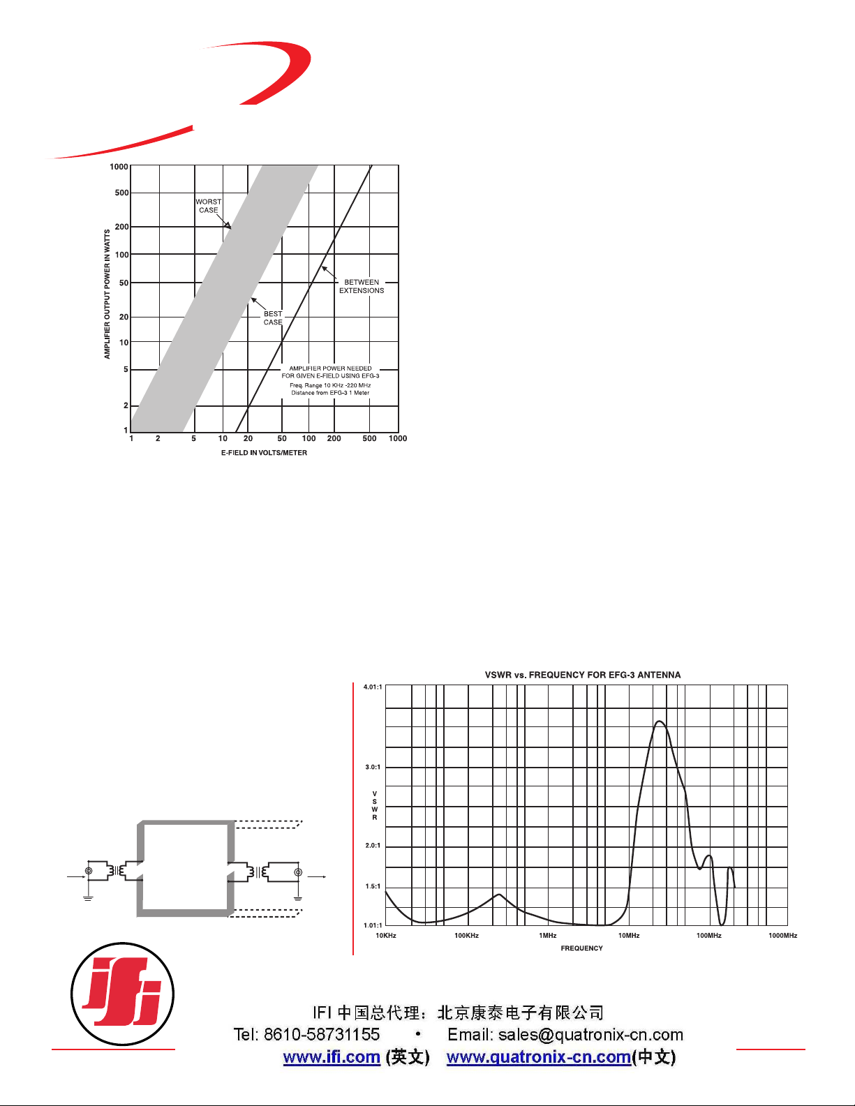
For objects too large to be placed between these extensions,
the EFG-3 may be used in an E-Field radiating mode. Fig. 2
shows the power required to generate a given field strength at a
distance of 1 meter from the plane surface of the antenna. EField radiation is a non-linear function of frequency, which
accounts for the wide band of related power and field strength,
taking into account best and worst case conditions. Reflections
can cause perturbations in the field distribution and widen the
effective curve width for a given power input and desired E-Field.
In selecting a power source for use with the EFG-3,
allowances should be made for these effects. The source should
be capable of supplying sufficient power for the worst case conditions, under given use for the full frequency spectrum.
Furthermore, there should be sufficient control over the power
source to permit attenuation for use under best case conditions.
Unlike similar high power antennas intended for
EMC/Susceptibility testing, the unused power is not dissipated in
the EFG-3 itself. A second set of broadband transformers are
employed to return the balanced loop 200 ohm termination
impedance to an unbalanced 50 ohm output; this allows system
termination with a conventional coaxial load. This output port
can be connected directly to a termination capable of dissipating the appropriate power levels.
The actual antenna pattern is a cardioid with the null at the
feed point where the antenna attaches to its horizontal pipe support. Both input and output connectors are located near this
point. The input port of the EFG-3 system does not present an
objectionable VSWR for most normal wide band laboratory
grade amplifiers over the full rated frequency spectrum. Fig. 3
shows a VSWR plot with respect to frequency for a standard
installation.
SERIES
INSTRUMENTS FOR INDUSTRY INC.
903 South Second Street, Ronkonkoma, NY 11779
Tel: 631-467-8400 • Fax: 631-467-8558 • E mail: sales@ifi.com
www.ifi.com
EFG-3 1000 watts
EFG-3B 2000 watts
E-Field Generating
Antenna
EFG-3/EFG-3B
POWER
IN
1:4
Z TRANSFORMER
TO
LOAD
4:1
Z TRANSFORMER
Fig. 1
Fig. 2
Fig. 3
 Loading...